
E3S-A - Capteurs de proximité OMRON - Notice d'utilisation et mode d'emploi gratuit
Retrouvez gratuitement la notice de l'appareil E3S-A OMRON au format PDF.


| Type de produit | Capteur photoelectrique amplifie integre |
| Marque | OMRON |
| Modele | E3S-A |
| Categorie | Capteurs de proximite |
| Methodes de detection | Barrage, Retrodirectif (polarise), Diffus reflechissant |
| Distances de detection | Barrage : 7 m ; Retrodirectif : 0,1 a 2 m ; Diffus : 10 cm, 20 cm, 70 cm |
| Alimentation | 10 a 30 V CC, ondulation 10 % max. |
| Consommation electrique | Jusqu'a 40 mA (emetteur + recepteur) + 15 mA avec fonction turbo |
| Type de sortie | Collecteur ouvert NPN ou PNP, 100 mA max., 30 VCC |
| Mode de fonctionnement | Light-ON ou Dark-ON (selectionnable) |
| Temps de reponse | 0,5 ms max. (operation et relachement) |
| Fonctions speciales | Autodiagnostic, entree de diagnostic externe, temporisateur OFF-delay 0-100 ms, fonction turbo |
| Protections de circuit | Court-circuit de charge, inversion de polarite, anti-interferences mutuelles (sauf barrage) |
| Indicateurs | LED rouge (incident), LED verte (stabilite), LED emetteur pour barrage |
| Materiaux du boitier | Polybutylene terephtalate, lentille en polyallulate denature |
| Poids | Type pre-cable : 60 g ; Type connecteur : 11 g |
| Indice de protection | IP67 (IEC), NEMA 4X |
| Temperature ambiante de fonctionnement | -25 a 55 degres C (sans givrage) |
| Humidite ambiante de fonctionnement | 35 a 85 % HR |
| Accessoires fournis | Support de montage, bouton de reglage de sensibilite, vis, capuchon de protection, refracteur (pour retrodirectif) |
| Entretien et nettoyage | Nettoyer les lentilles avec un chiffon doux et sec. Eviter les solvants. |
| Securite | Respecter la tension d'alimentation nominale. Ne pas utiliser de redresseurs non regules. Eviter les chocs mecaniques. |
| Reparabilite et pieces detachees | Pieces detachees disponibles : fentes, supports, reflecteurs. Contacter le service apres-vente OMRON. |
FOIRE AUX QUESTIONS - E3S-A OMRON
Questions des utilisateurs sur E3S-A OMRON
0 question sur cet appareil. Repondez a celles que vous connaissez ou posez la votre.
Poser une nouvelle question sur cet appareil
Téléchargez la notice de votre Capteurs de proximité au format PDF gratuitement ! Retrouvez votre notice E3S-A - OMRON et reprennez votre appareil électronique en main. Sur cette page sont publiés tous les documents nécessaires à l'utilisation de votre appareil E3S-A de la marque OMRON.
MODE D'EMPLOI E3S-A OMRON
Built-in Amplifier Photoelectric Sensor
E3S-A
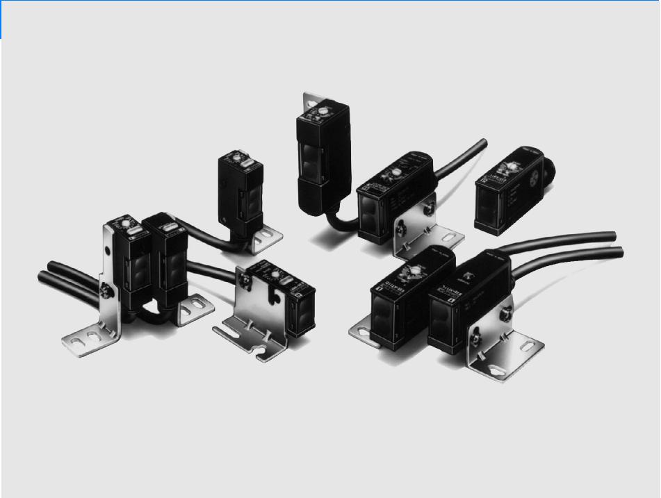
Ordering Information
E3S-A General-purpose Sensors
| Connections | Appearance | Sensing method | Sensing distance | Operating modes | Output / timer functions | Model | |
| NPN output | PNP output | ||||||
| Prewired | Horizontal | Through-beam | 7 m | Light-ON Dark-ON (selectable) | --- | E3S-AT11 | E3S-AT31 |
| With timer and self-diagnostic functions | E3S-AT21 | E3S-AT41 | |||||
| Retroreflective | 0.1 to 2 m (polarized) | --- | E3S-AR11 | E3S-AR31 | |||
| With timer and self-diagnostic functions | E3S-AR21 | E3S-AR41 | |||||
| Diffuse reflective | 10 cm (light source: infra-red) | --- | E3S-AD13 | E3S-AD33 | |||
| With timer and self-diagnostic functions | E3S-AD23 | E3S-AD43 | |||||
| 20 cm | --- | E3S-AD11 | E3S-AD31 | ||||
| With timer and self-diagnostic functions | E3S-AD21 | E3S-AD41 | |||||
| 70 cm (light source: infra-red) | --- | E3S-AD12 | E3S-AD32 | ||||
| With timer and self-diagnostic functions | E3S-AD22 | E3S-AD42 | |||||
Accessories (Order Separately)
| Connections | Appearance | Sensing method | Sensing distance | Operating modes | Output / timer functions | Model | |
| NPN output | PNP output | ||||||
| Prewired | Vertical | Through-beam | 7 m | Light-ON Dark-ON (selectable) | --- | E3S-AT61 | E3S-AT81 |
| With timer and self-diagnostic functions | E3S-AT71 | E3S-AT91 | |||||
| Retroreflective | 0.1 to 2 m (polarized) | --- | E3S-AR61 | E3S-AR81 | |||
| With timer and self-diagnostic functions | E3S-AR71 | E3S-AR91 | |||||
| Diffuse reflective | 10 cm (light source: infra-red) | --- | E3S-AD63 | E3S-AD83 | |||
| With timer and self-diagnostic functions | E3S-AD73 | E3S-AD93 | |||||
| 20 cm | --- | E3S-AD61 | E3S-AD81 | ||||
| With timer and self-diagnostic functions | E3S-AD71 | E3S-AD91 | |||||
| 70 cm (light source: infra-red) | --- | E3S-AD62 | E3S-AD82 | ||||
| With timer and self-diagnostic functions | E3S-AD72 | E3S-AD92 | |||||
| Connector | Horizontal | Through-beam | 7 m | --- | E3S-AT16 | E3S-AT36 | |
| Retroreflective | 0.1 to 2 m (polarized) | E3S-AR16 | E3S-AR36 | ||||
| Diffuse reflective | 10 cm (light source: infra-red) | E3S-AD18 | E3S-AD38 | ||||
| 20 cm | E3S-AD16 | E3S-AD36 | |||||
| 70 cm (light source: infra-red) | E3S-AD17 | E3S-AD37 | |||||
| Vertical | Through-beam | 7 m | --- | E3S-AT66 | E3S-AT86 | ||
| Retroreflective | 0.1 to 2 m (polarized) | E3S-AR66 | E3S-AR86 | ||||
| Diffuse reflective | 10 cm (light source: infra-red) | E3S-AD68 | E3S-AD88 | ||||
| 20 cm | E3S-AD66 | E3S-AD86 | |||||
| 70 cm (light source: infra-red) | E3S-AD67 | E3S-AD87 | |||||
E3S-A General-purpose Sensor Accessories
| Name | Model | Remarks |
| Slit for Through-beam Sensor | E39-S46 | 2 mm, 1 mm, and 0.5 mm slits are sold in pairs, one each for the receiver and emitter of a through-beam model |
| Mounting Bracket for Vertical Sensor | E39-L59 | Purchase two brackets for each through-beam model |
| E39-L81 | ||
| Filter for Mutual Interference Prevention (for Through-beam Sensor) | E39-E6 | 4 filters are sold together for two through-beam models (2 filters each for the emitters and receivers) |
| Reflector for Optical Axis Adjustment (for Through-beam Sensor) | E39-R5 | One only |
Plugs (for Sensors with Connector Terminals)
| Cord | Appearance | Cord length | Model | |
| Standard | Straight (3 conductor) | 2 m | XS2F-D421-DC0-A | |
| 5 m | XS2F-D421-GC0-A | |||
| L-shape (3 conductor) | 2 m | XS2F-D422-DC0-A | ||
| 5 m | XS2F-D422-GC0-A | |||
| Robot (vibration-proof) | Straight (4 conductor) | 2 m | XS2F-D421-D80-R | |
| 5 m | XS2F-D421-G80-R | |||
| L-shape (43 conductor) | 2 m | XS2F-D422-D80-R | ||
| 5 m | XS2F-D422-G80-R | |||
Reflectors
| Name | Model | Remarks |
| Mini-reflector | E39-R4 | One |
| Small Reflector | E39-R3 | One |
| Reflector Tape | E39-RS1, RS2, RS3 | One (sealed type) |
Specifications
Without self-diagnostic functions
| Sensing method | Through-beam, Retroflective (polarized) | Diffuse reflective: 10 cm | Diffuse reflective: 20 cm | Diffuse reflective: 70 cm | |
| Model | NPN output | E3S-AT11, -AR11 | E3S-AD13 | E3S-AD11 | E3S-AD12 |
| E3S-AT16, -AR16 | E3S-AD63 | E3S-AD16 | E3S-AD17 | ||
| E3S-AT61, -AR61 | E3S-AD18 | E3S-AD61 | E3S-AD62 | ||
| E3S-AT66, -AR66 | E3S-AD68 | E3S-AD66 | E3S-AD67 | ||
| PNP output | E3S-AT31, -AR31 | E3S-AD33 | E3S-AD31 | E3S-AD32 | |
| E3S-AT36, -AR36 | E3S-AD83 | E3S-AD36 | E3S-AD37 | ||
| E3S-AT81, -AR81 | E3S-AD38 | E3S-AD81 | E3S-AD82 | ||
| E3S-AT86, -AR86 | E3S-AD88 | E3S-AD86 | E3S-AD87 | ||
| Wavelength of LED light source | 700 nm (red) | 880 nm (infrared) | 700 nm (red) | 880 nm (infrared) | |
| Sensitivity adjustment | Two-turn (endless) sensitivity adjustor with indicator | ||||
| Self-diagnostic functions | --- | ||||
| Timer | --- | ||||
| Turbo function | --- | ||||
| Method of connection | Prewired / connector | ||||
| Weight | Prewired type: 60 g; connector type: 11 g | ||||
| Operation mode | Dark-ON or Light-ON (switchable) | ||||
| Output | Open collector current output (NPN or PNP) | ||||
| Circuit protection | Load short-circuit protection, reverse connection protection, mutual interference prevention (except for through-beam models) | ||||
| Indicators | Light indicator (red) and stability indicator (green); emission indicator (red) for the emitter of through-beam models | ||||
| Materials | Case: Polybutylene terephthalate Lens: Denaturated polyallulate Mounting bracket: Stainless steel (SUS304) | ||||
| Attachments | Mounting bracket, sensitivity adjustor knob, screws, sensitivity adjustor cover, close-mounting plate (only for Sensors with connector terminals) and reflector (E39-R1: only for retroreflective Sensors) | ||||
With self-diagnostic functions
| Sensing method | Through-beam, Retroflective (polarized) | Diffuse reflective: 10 cm | Diffuse reflective: 20 cm | Diffuse reflective: 70 cm | |
| Model | NPN output | E3S-AT21 | E3S-AD23 | E3S-AD21 | E3S-AD22 |
| E3S-AR21 | E3S-AD73 | E3S-AD71 | E3S-AD72 | ||
| E3S-AT71 | |||||
| E3S-AR71 | |||||
| PNP output | E3S-AT41 | E3S-AD43 | E3S-AD41 | E3S-AD42 | |
| E3S-AR41 | E3S-AD93 | E3S-AD91 | E3S-AD92 | ||
| E3S-AT91 | |||||
| E3S-AR91 | |||||
| Wavelength of LED light source | 700 nm (red) | 880 nm (infrared) | 700 nm (red) | 880 nm (infrared) | |
| Sensitivity adjustment | Two-turn (endless) sensitivity adjustor with indicator | ||||
| Self-diagnostic functions | Self-diagnostic output, External diagnostic input | Self-diagnostic output | |||
| Timer | 0 to 100 ms OFF-delay variable adjustor | ||||
| Turbo function | Yes (with turbo switch) | --- | |||
| Method of connection | Prewired | ||||
| Weight | 60 g | ||||
| Operation mode | Dark-ON or Light-ON (switchable) | ||||
| Output | Open collector current output (NPN or PNP) | ||||
| Circuit protection | Load short-circuit protection, reverse connection protection, mutual interference prevention (except for through-beam models) functions | ||||
| Indicators | Light indicator (red) and stability indicator (green); emission indicator (red) for the emitter of the through-beam model | ||||
| Materials | Case: Polybutylene terephthalate Lens: Denaturaled polyallalate Mounting bracket: Stainless steel (SUS304) | ||||
| Attachments | Mounting bracket, sensitivity adjustor knob, screws, sensitivity adjustor cover, close-mounting plate (only for Sensors with connector terminals) and reflector (E39-R1: only for retroreflective Sensors) | ||||
Ratings / Characteristics
| Item | Through-beam | Retroreflective | Diffuse reflective | ||||
| E3S-AT11, 16, 21, 31, 36, 41, 61, 66, 71, 81, 86, 91 | E3S-AR11, 16, 21, 31, 36, 41, 61, 66, 71, 81, 86, 91 | E3S-AD23, 43, 73, 93 | E3S-AD13, 18, 33, 38, 63, 68, 83, 88 | E3S-AD11, 16, 21, 31, 36, 41, 61, 66, 71, 81, 86, 91 | E3S-AD12, 17, 22, 32, 37, 42, 62, 67, 72, 82, 87, 92 | ||
| Power supply voltage | 10 to 30 V DC, ripple: 10% max. | ||||||
| Current consumption | 40 mA max. (emitter and receiver) plus approx. 15 mA with turbo function | 30 mA max. plus approx. 15 mA with turbo function | 35 mA max. | 30 mA max. plus approx. 15 mA with turbo function | 35 mA max. | ||
| Rated sensing distance | White mat paper | 0 to 7 m | 0.1 to 2 m | 0.1 to 10 cm | 0.1 to 20 cm | 0 to 70 cm | |
| Black mat paper | 0 to 7 m | 0.1 to 2 m | 0.3 to 2.5 cm | 0.5 to 20 cm | 0.15 to 33 cm | ||
| Standard sensing object (white mat paper) | 7 mm min. | 30 mm min. | 10 x 10 cm | 20 x 20 cm | |||
| Variation in sensing distance | --- | 30%/0% max. | |||||
| Hysteresis | --- | 20% max. | 10% max. | 20% max. | |||
| Sensing distance with attachment | E39-E6: 2.4 m2-mm slit: 2.5 m1-mm slit: 1.1 m0.5-mm slit: 0.5 m | E39-R3:10 to 130 cmE39-R4: 7 to 60 cmE39-RSA:10 to 60 cmE39-RSB:10 to 30 cm | --- | ||||
| Min. sensing object | without slit: 2.0 mm2-mm slit: 0.8 mm1-mm slit: 0.4 mm0.5-mm slit: 0.2 mm | E39-R1 Reflector:10 mmE39-R3: 3 mmE39-R4: 1.0 mm | --- | ||||
| Difference in direction between optical axis and mounting direction | ±2° max. (checked along extended line in the mounting direction) | ±2° max. | |||||
| Response time | 0.5 ms max. for both operation and release | ||||||
| Control output | 30 VDC, 100 mA max. (residual voltage: 1 V max.) Open collector (residual voltage: 0.4 V max. at 16 mA) | ||||||
| Self-diagnostic output | Only Sensors with self-diagnostic function: 50 mA max, 30 VDC (residual voltage: 1 V max.), open collector (residual voltage: 0.4 V max. 16 mA) | ||||||
| External diagnostiic input | Input Voltage | With emitter OFF:NPN: 0 V short-circuit or 1.5 V max. (push current: 1 mA max.)PNP: DC short-circuit or -1.5 V DC max.(pull current: 3 mA max.)With emitter ON: NPN/PNPOpen (max. input voltage: 30 V max. with 0.1 mA current leakage) | --- | ||||
| Response time | 0.5 ms max. | ||||||
| Ambient illumination | Incandescent lamp: Illumination on optical spot: 5,000 lx max.Sunlight: Illumination on optical spot: 10,000 lx max. | ||||||
| Ambient temperature | Operating: -25°C to 55°C (with no icing)Storage: -40°C to 70°C (with no icing) | ||||||
| Ambient humidity | Operating: 35% to 85%Storage: 35% to 95% | ||||||
| Insulation resistance | 20 MW min. (at 500 V DC) | ||||||
| Dielectric strength | 1,000 V AC, 50/60 Hz for 1 min | ||||||
| Vibration resistance | Destruction: 10 to 55 Hz, 1.5-mm double amplitude (30G) 2 hrs each in three directions | ||||||
| Shock resistance | Destruction: Approx. 50G 3 times each in three directions | ||||||
| Enclosure ratings | IEC: IP67; NEMA: 4X | ||||||
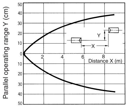
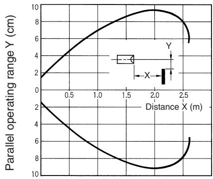
Parallel Operating Range (Typical)
E3S-AT□1
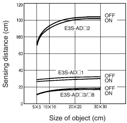
Sensing Distance vs. Object Size E3S-AD
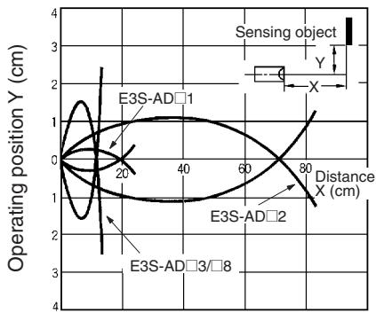
Operating Range (Typical)
E3S-AD□ (Left and Right)
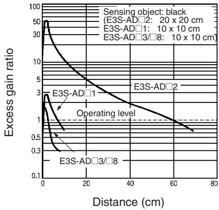
Excess Gain vs. Set Distance
E3S-AT□1 (Typical)
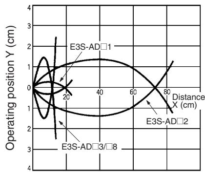
E3S-AD (Up and Down)
E3S-AD□1,-AD□2,-AD□3,-AD□8
(Detection of White Paper)
Reflector Parallel Movement E3S-AR□1 (Typical)
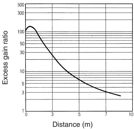
E3S-AR□1 (With Reflector E39-R1)

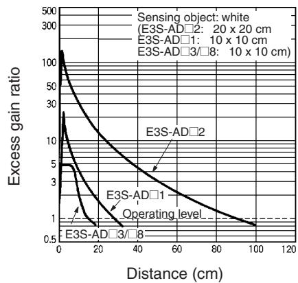
E3S-AD□1, -AD□2, -AD□3, -AD□8 (Detection of White Paper)
Output Circuits
| Type | Model | Mode switch | Output transistor | Output circuit | |
| NPN | E3S-AT11 | Light ON | ON when light is received | Emitter E3S-AT11/AT16/AT61/AT66 | Brown 10 to 30 VDC |
| E3S-AT16 | |||||
| E3S-AT61 | |||||
| E3S-AT66 | |||||
| E3S-AR11 | |||||
| E3S-AR16 | |||||
| E3S-AR61 | |||||
| E3S-AR66 | |||||
| E3S-AD13 | |||||
| E3S-AD63 | |||||
| E3S-AD18 | |||||
| E3S-AD68 | |||||
| E3S-AD11 | |||||
| E3S-AD16 | |||||
| E3S-AD61 | |||||
| E3S-AD66 | |||||
| E3S-AD12 | |||||
| E3S-AD17 | |||||
| E3S-AD62 | |||||
| E3S-AD67 | |||||
| Dark ON | ON when light is not received | Connector Type Emitter | Reflective/Receiver Pin No.2 is open. | ||
| ① ② ④ ⑤ 0 V | ① ② ④ ⑤ Output(Relay) 0 V | ||||
| E3S-AT21 | Light ON | ON when light is received | Emitter E3S-AT21/AT71 | 10 to 30 VDC | |
| Green Pink External diagnostic input LED for emitter Indicator(red) | ON OFF | ||||
| Blue 0 V | ON OFF | ||||
| Dark ON | ON when light is not received | Light Stability (Red) Main circuit 100 mA max. Black Control output Self-diagnostic output Blue Z: Vz=39 V | |||
| E3S-AR21 | Light ON | ON when light is received | Light Stability (Red) Main circuit 100 mA max. Black Control output Self-diagnostic output Blue Z: Vz=39 V | ||
| E3S-AR71 | Dark ON | ON when light is not received | |||
| PNP | E3S-AT31 | Light ON | ON when light is received | Emitter E3S-AT31/AT36/AT81/AT86 | Brown 10 to 30 VDC |
| E3S-AT36 | |||||
| E3S-AT81 | |||||
| E3S-AT86 | |||||
| E3S-AR31 | |||||
| E3S-AR36 | |||||
| E3S-AR81 | |||||
| E3S-AR86 | |||||
| E3S-AD33 | |||||
| E3S-AD83 | |||||
| E3S-AD38 | |||||
| E3S-AD88 | |||||
| E3S-AD31 | |||||
| E3S-AD36 | |||||
| E3S-AD81 | |||||
| E3S-AD86 | |||||
| E3S-AD32 | |||||
| E3S-AD37 | |||||
| E3S-AD82 | |||||
| E3S-AD87 | |||||
| Dark ON | ON when light is not received | Connector Type Emitter | Reflective/Receiver Pin No. 2 is open. | ||
| E3S-AT41 | Light ON | ON when light is received | Emitter E3S-AT41/AT91 | ON OFF | |
| E3S-AT91 | |||||
| E3S-AD43 | |||||
| E3S-AD93 | |||||
| E3S-AD41 | |||||
| E3S-AD91 | |||||
| E3S-AD42 | |||||
| E3S-AD92 | |||||
| Dark ON | ON when light is not received | Light Stability (Red) (Green) | 50 mA max. | Control output (Relay) | |
| E3S-AR41 | Light ON | ON when light is received | Light Stability (Red) (Green) | 4.4K Z0 50 mA max. | |
| E3S-AR91 | Dark ON | ON when light is not received | |||
Timing Charts
| Type | Model | Mode switch | Output transistor | Timing chart | |
| NPN | E3S-AT11 | Light ON | ON when light is received. | Light received Light not received Light indicator (Red) ON OFF Output transistor ON OFF Load (relay) Operate Release | (Between brown and black) |
| E3S-AT16 | |||||
| E3S-AT61 | |||||
| E3S-AT66 | |||||
| E3S-AR11 | |||||
| E3S-AR16 | |||||
| E3S-AR61 | |||||
| E3S-AR66 | |||||
| E3S-AD13 | |||||
| E3S-AD63 | |||||
| E3S-AD18 | Dark ON | ON when light is not received. | Light received Light not received Light indicator (Red) ON OFF Output transistor ON OFF Load (relay) Operate Release | (Between brown and black) | |
| E3S-AD68 | |||||
| E3S-AD11 | |||||
| E3S-AD16 | |||||
| E3S-AD61 | |||||
| E3S-AD66 | |||||
| E3S-AD12 | |||||
| E3S-AD17 | |||||
| E3S-AD62 | |||||
| E3S-AD67 | |||||
| E3S-AT21 | Light ON | ON when light is received. | Light received Light not received Light indicator (Red) ON OFF Output transistor ON OFF Load (relay) Operate Release | (T: Off-delay timer (0 to 100 ms) (Between brown and black) | |
| E3S-AT71 | |||||
| E3S-AD23 | |||||
| E3S-AD73 | |||||
| E3S-AD21 | |||||
| E3S-AD71 | |||||
| E3S-AD22 | |||||
| E3S-AD72 | |||||
| E3S-AR21 | |||||
| E3S-AR71 | |||||
| Dark ON | ON when light is not received. | Light received Light not received Light indicator (Red) ON OFF Output transistor ON OFF Load (relay) Operate Release | (T: Off-delay timer (0 to 100 ms) (Between brown and black) | ||
| PNP | E3S-AT31 | Light ON | ON when light is received. | Light received Light not received Light indicator ON (Red) OFF Output transistor ON OFF Load (relay) Operate Release | (Between blue and black) |
| E3S-AT36 | |||||
| E3S-AT81 | |||||
| E3S-AT86 | |||||
| E3S-AR31 | |||||
| E3S-AR36 | |||||
| E3S-AR81 | |||||
| E3S-AR86 | |||||
| E3S-AD33 | |||||
| E3S-AD83 | |||||
| E3S-AD38 | Dark ON | ON when light is not received. | Light received Light not received Light indicator ON (Red) OFF Output transistor ON OFF Load (relay) Operate Release | (Between blue and black) | |
| E3S-AD88 | |||||
| E3S-AD31 | |||||
| E3S-AD36 | |||||
| E3S-AD81 | |||||
| E3S-AD86 | |||||
| E3S-AD32 | |||||
| E3S-AD37 | |||||
| E3S-AD82 | |||||
| E3S-AD87 | |||||
| E3S-AT41 | Light ON | ON when light is received. | Light received Light not received Light indicator ON (Red) OFF Output transistor ON OFF Load (relay) Operate Release | (T: Off-delay timer (0 to 100 ms) (Between blue and black) | |
| E3S-AT91 | |||||
| E3S-AD43 | |||||
| E3S-AD93 | |||||
| E3S-AD41 | |||||
| E3S-AD91 | |||||
| E3S-AD42 | |||||
| E3S-AD92 | |||||
| E3S-AR41 | |||||
| E3S-AR91 | |||||
| Dark ON | ON when light is not received. | Light received Light not received Light indicator ON (Red) OFF Output transistor ON OFF Load (relay) Operate Release | (T: Off-delay timer (0 to 100 ms) (Between blue and black) | ||
Self-diagnostic Function
With this function, the E3S-A checks changes in environmental conditions (especially a change in the ambient temperature) and self-diagnoses the resistance against the changes. The result is shown by the indicators or an output signal.
| Amount of incident light | Green indicator | Indicator | Incident light indicator (red) | Self-diagnostic function | Self-diagnostic example |
| 1.2 or more | Stable operating state with inci-dent light: Stable operation is expected in the rat- ed temperature range with the green indicator ON. | Green Red | With light inci- dent (red induca- tor: ON) | --- | --- |
| 1.0 to 1.2 | Conditional oper- ating state with incident light: Stable operation is expected if the temperature fluc-tuation is within ±10% of the pri- mary tempera- ture. | Green Red | The self-diag- nostic alarm output alerts the user to this state if it contin- ues for 0.3 s. | The optical axis misaligned by vibration. Light decreased by dust. Dust | |
| 0.8 to 1.0 | Green Red | Without light inci- dent (red induca- tor: OFF) | With light leakage (through-beam and retroreflective Sensors) Sensing object Light reflected from the floor or the back- ground (diffuse reflective Sensors) Sensing object Noise | ||
| 0.8 or less | Stable operating state with no inci- dent light: Stable operation is ex- pected in the rat- ed temperature range with the green indicator ON. | Green Red | --- | --- |
External Diagnostic Input Function
To switch the emission off, short-circuit the pink and the blue cords of the emitter of the E3S-AT or the E3S-AR with the NPN output feature. For the E3S-AT or the E3S-AR with the PNP output feature, short-circuit the pink and the brown cords. With this function, the operating status can be checked before operation.
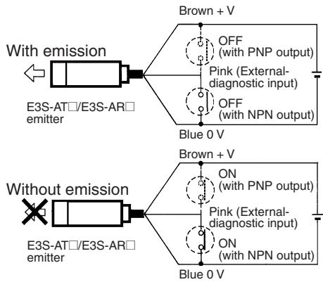
E3S-AT/E3S-AR Emitter
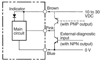
External diagnostic input LED for emitter Indicator
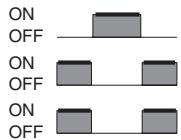
The sensor is normal if the control output varies when the self-diagnostic external input is ON and OFF. The sensor is abnormal if the control output does not vary when the self-diagnostic external input is turned ON or OFF.
Note:Before using the self-diagnostic external input function, the incident light beam to the sensor must not be blocked by an object.
Timer and Turbo Switch (Sensors with Self-diagnostic Output Function)
The E3S-A Sensor equipped with the self-diagnostic feature incorporates an OFF-delay timer that can be adjusted within a range of 0 to 100 ms.
The emitter of the through-beam sensor with the self-diagnostic feature incorporates a turbo switch. When this switch is on, the intensity of the red LED light source can be increased to
make a brighter spot. The OFF-delay time adjustor of the retroreflective and the 20-cm diffuse reflective sensor is used as a turbo switch. When the adjustor is pressed, it functions as a turbo switch to automatically increase the power of the light source to create a brighter light spot. Do not press the adjustor when turning it
Sensitivity Adjustment (Reflective Sensors)
| Item | Position A | Position B | Setting | ||||
| Sensing condition | Photoelectric sensor Sensing object | Photoelectric sensor Sensing object | --- | ||||
| Sensitivity adjustor | A Min Max | B Min Max | A B Min MAX | ||||
| Indicators | OFF STABILITY (green) ON LIGHT (red) | OFF STABILITY (green) ON LIGHT (red) | OFF STABILITY (green) ON LIGHT (red) | ||||
| Procedure | Locate a sensing object at the sensing distance, set the sensitivity adjustor to the minimum scale position, and gradually increase sensitivity by turning the sensitivity adjustor clockwise until the incident light indicator (red LED) is ON. Position A is where the indicator has turned ON. Regard the maximum scale position as Position A if the indicator does not turned ON at full sensitivity. | Remove the sensing object and gradually decrease sensitivity by turning the sensitivity adjustor counterclockwise from the maximum scale position until the incident light indicator (red LED) is OFF. Position B is where the indicator has turned off. Regard the minimum scale position as Position B if the indicator does not turned ON at minimum sensitivity. | Set the sensitivity indicator to the position between Positions A and B (in some cases, Positions A and B are opposite of the above example). The photoelectric sensor will then work normally if the stability indicator (green) is lit with and without the sensing object. If it is not lit, stable operation cannot be expected, in which case a different detection method must be applied. | ||||
Unlike conventional photoelectric sensors, the variation in the sensitivity of E3S photoelectric sensors is minimal. This means the sensitivity can be adjusted on only a single photoelectric sensor, and then the adjustors on the other photoelectric sensors can be set to the same scale position. There is no need to adjust the sensitivity of each photoelectric sensor individually.
Turbo Function (Turbo Switch)
With the turbo function switched ON, the light spot is visible even at a distance of 20~cm , making it easy to check the sensing position and the angle of the optical axis.
- After using the turbo function, readjust the OFF-delay time that had been set, since the OFF-delay time could have been changed when the turbo switch (which is on the OFF-delay time adjustor) was pressed.
- Press the OFF-delay time adjustor to switch ON the turbo function with a maximum force of 1kg and within a maximum period of 3 mins. (The photoelectric sensor, however, will not malfunction even if the turbo function is switched on for more than 3 mins.)
With Turbo Switch ON
The turbo function is effective with the turbo switch pressed, and the function is reset automatically when released.

Normal Operating Condition

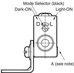
Operating Mode Selection
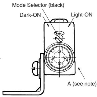
As shown in the following illustration, the E3S-A has an operating mode selector on the panel where the Receiver connector is located. With this operating mode selector, the E3S-A is in either dark-ON or light-ON mode.
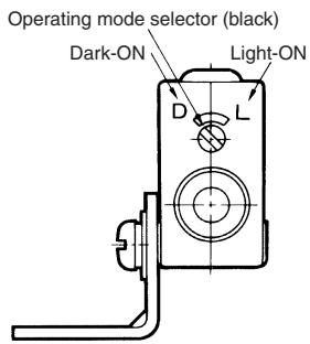
Sensors
Prewired Type
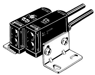
E3S-AT11, E3S-AT31 (Receiver)
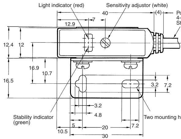
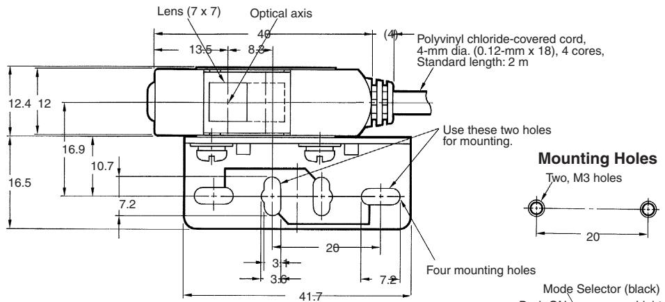
Polyvinyl chloride-covered cord, 4-mm dia. (0.12-mm x 18), 4 cores, Standard length: 2 m
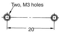
Mounting Holes
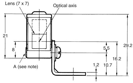
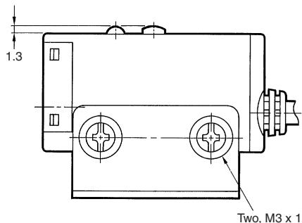
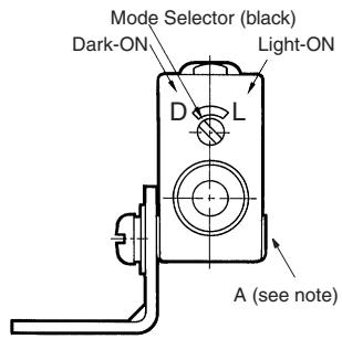
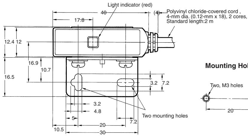
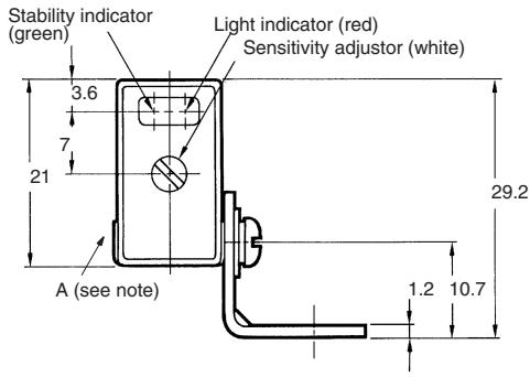
Note: The mounting bracket can be attached to side A.
E3S-AT11, E3S-AT31 (Emitter)
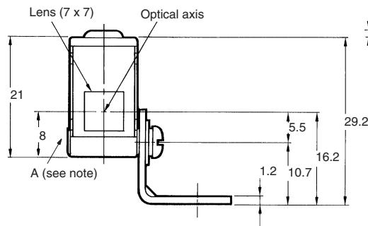
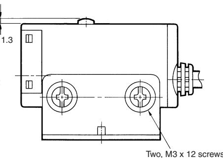
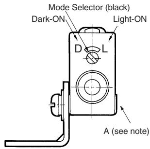
Note: The mounting bracket can be attached to side A.
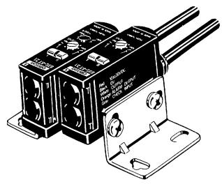
E3S-AT21, E3S-AT41 (Receiver)
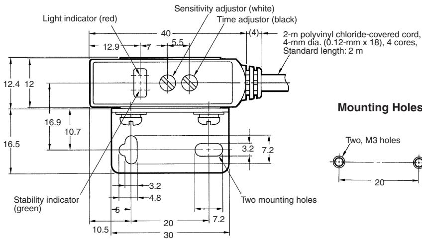
Mounting Holes
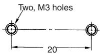
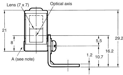
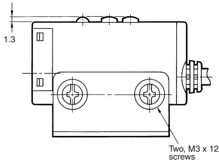
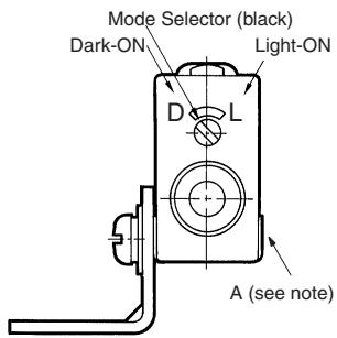
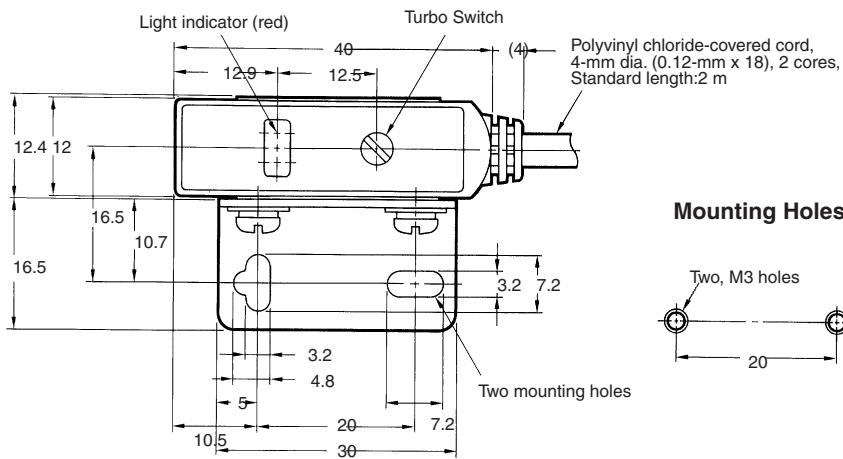
Note: The mounting bracket can be attached to side A.
E3S-AT21, E3S-AT41 (Emitter)
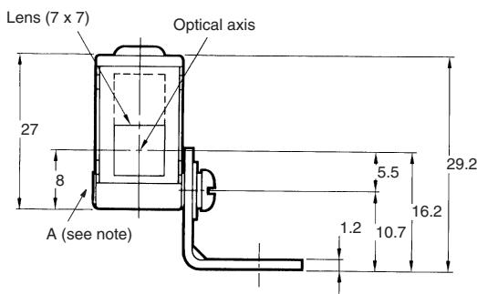
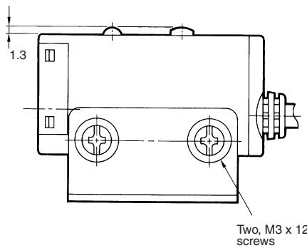
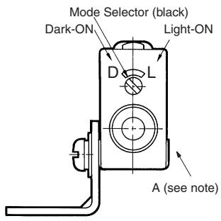
Note: The mounting bracket can be attached to side A.
E3S-AR11, E3S-AR31
E3S-AR21, E3S-AR41
OEE-delay time adjustor/turbo switch (black) (see
Note 1
Turn to adjust the OFF-delay time: push to switch
turn to adjust theturbo function ON
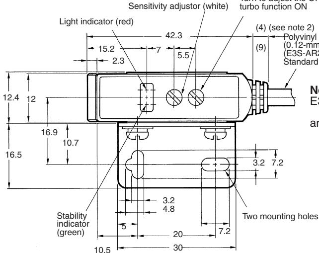
Note: 1. For E3S-AR21 and
E3S-AR41 only.
- 9 mm for E3S-AR21
and E3S-AR41
Mounting Holes
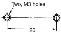
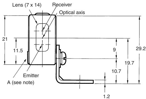
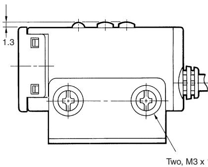
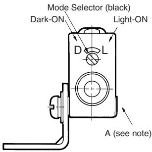
Note: The mounting bracket can be attached to side A.
E3S-AD11. E3S-AD31
E3S-AD13. E3S-AD31
E3S-AD12, E3S-AD32
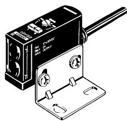
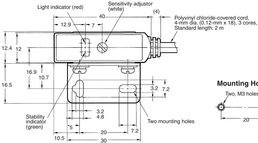
Mounting Holes
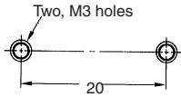
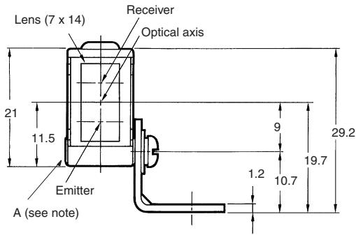
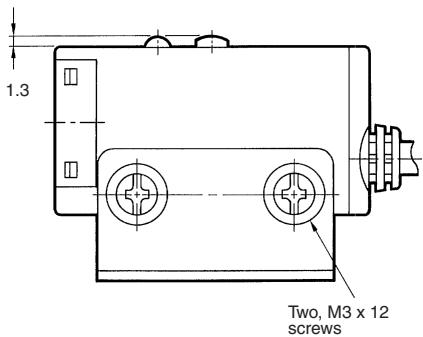
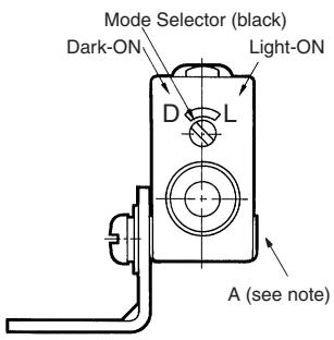
Note: The mounting bracket can be attached to side A.
E3S-AD21, E3S-AD41
E3S-AD23,E3S-AD43
E3S-AD22, E3S-AD42
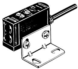
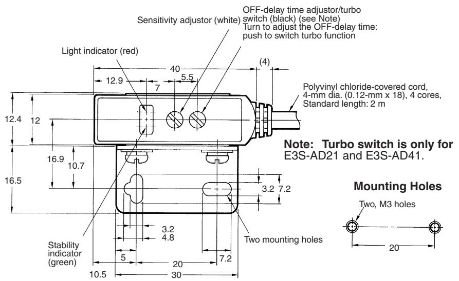
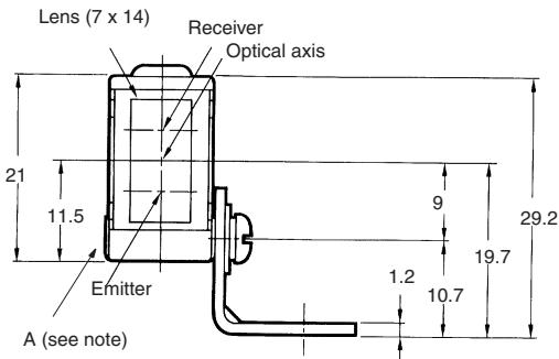
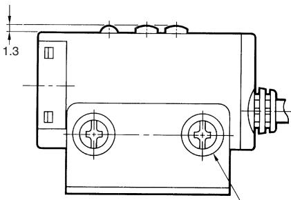
Two, M3 x 12 screws
Note: The mounting bracket can be attached to side A.
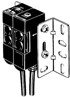
E3S-AT61, E3S-AT81 (Receiver)
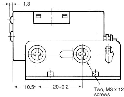
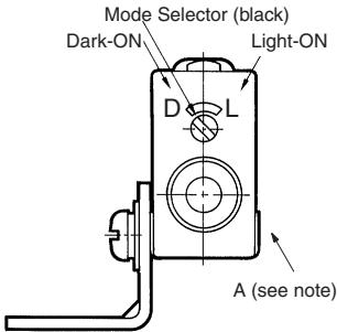
Note: The mounting bracket can be attached to side A.
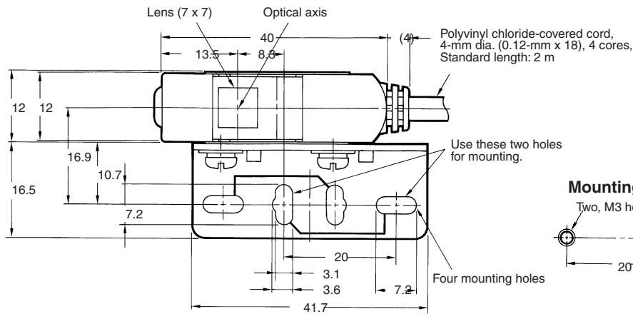
E3S-AT61, E3S-AT81 (Emitter)


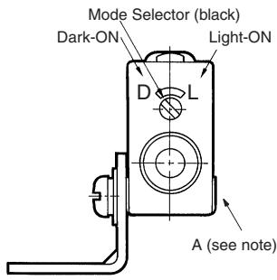
Note: The mounting bracket can be attached to side A.
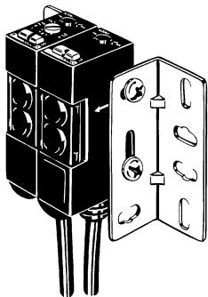
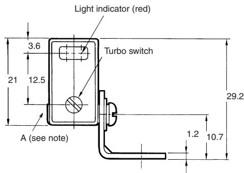
E3S-AT71, E3S-AT91 (Receiver)
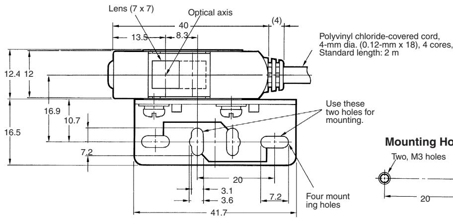
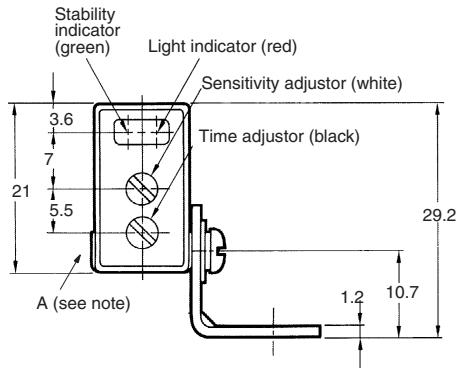
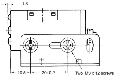
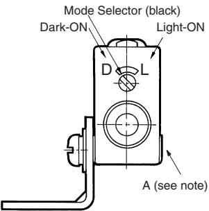
Note: The mounting bracket can be attached to side A.
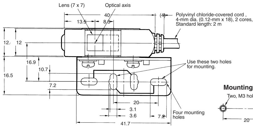
E3S-AT71, E3S-AT91 (Emitter)
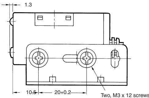
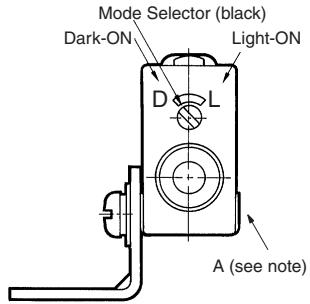
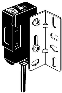
Note: The mounting bracket can be attached to side A.
E3S-AR61, E3S-AR81
E3S-AR71, E3S-AR91
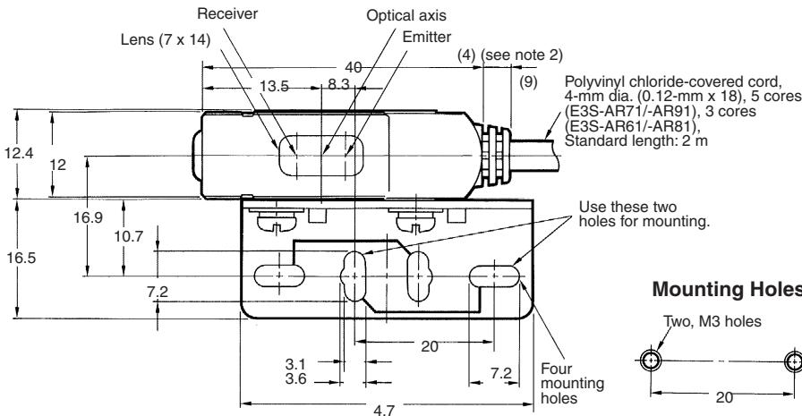
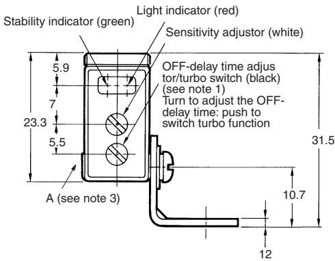
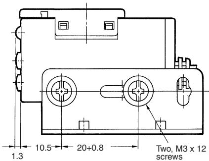
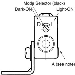
Note: 1. Turbo switch is only for E3S-AR71 and E3S-AR91.
2. 9.7 mm for E3S-AR71/-AR91.
3. The mounting bracket can be attached to side A.
E3S-AD61, E3S-AD81
E3S-AD63, E3S-AD83
E3S-AD62, E3S-AD82
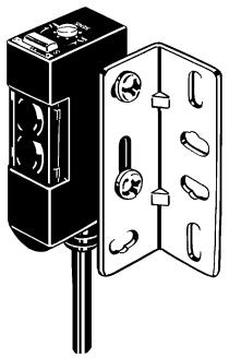
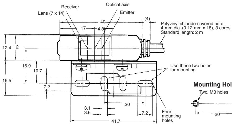
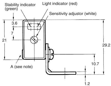
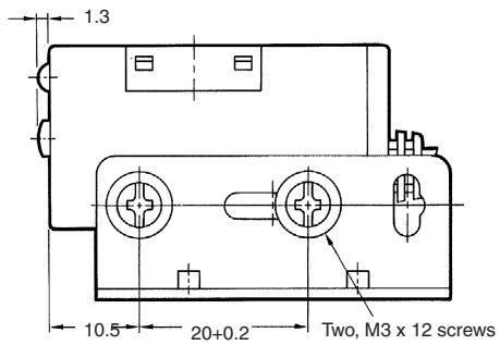
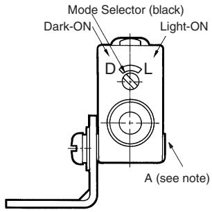
E3S-AD71, E3S-AD91
E3S-AD73, E3S-AD93
E3S-AD72, E3S-AD92
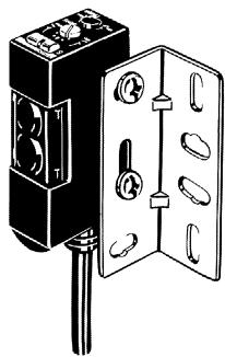
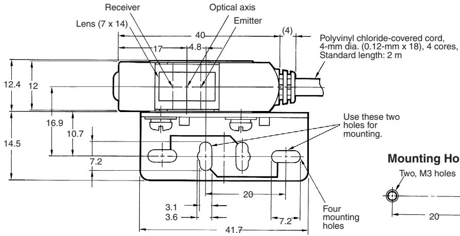
Note: The mounting bracket can be attached to side A.
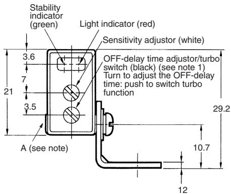
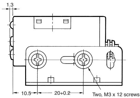
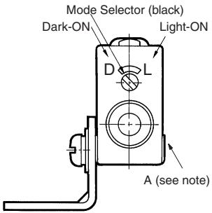
Note: 1. Turbo switch is only for E3S-AD71 and E3S-AD91.
2. The mounting bracket can be attached to side A.
Connector Type
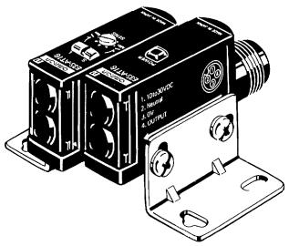
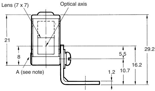
E3S-AT16, E3S-AT36 (Receiver)
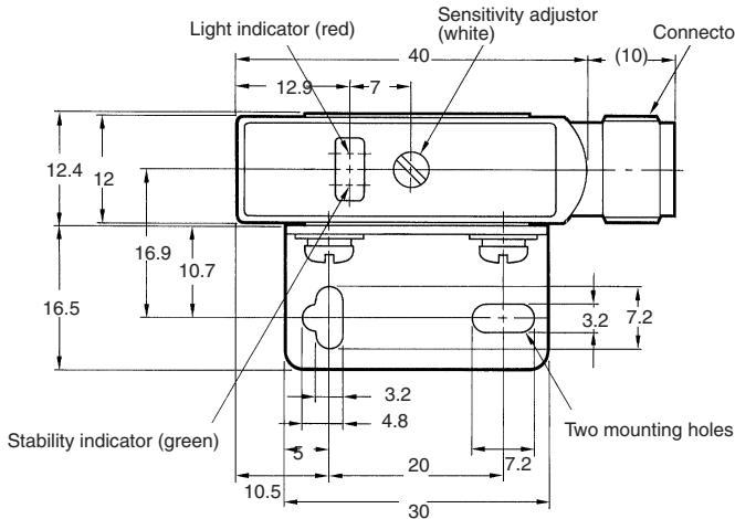
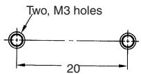
Mounting Holes
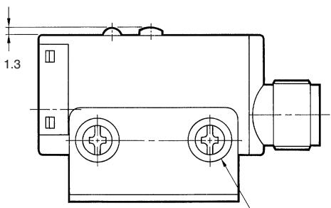
Two, M3 x 12 screws
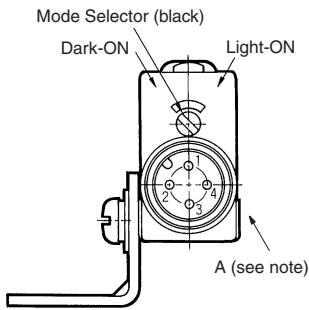
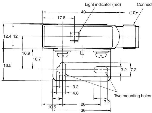
Note: The mounting bracket can be attached to side A.
E3S-AT16, E3S-AT36 (Emitter)
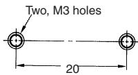
Mounting Holes
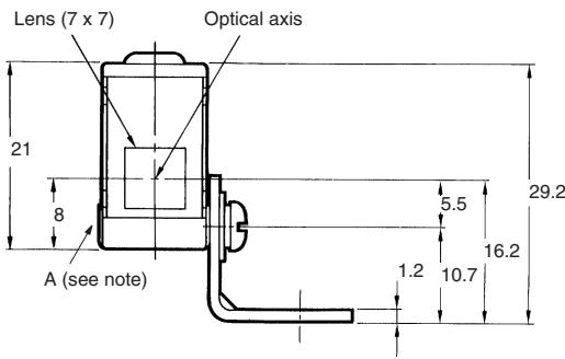
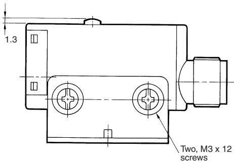
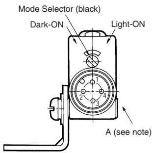
Note: The mounting bracket can be attached to side A.
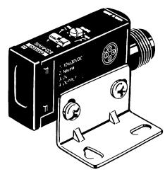
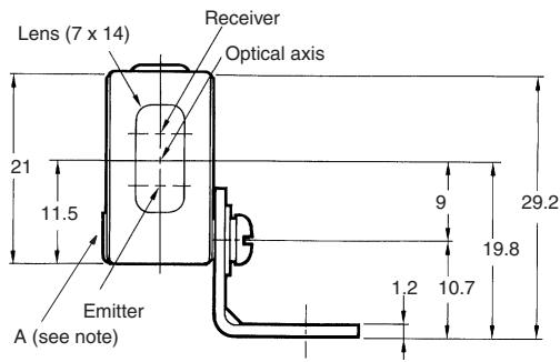
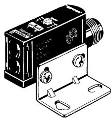
E3S-AR16,E3S-AR36
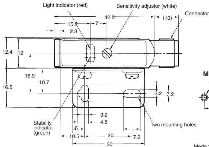
Mounting Holes
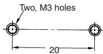
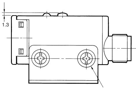
Two, M3 x 12 screws
Note: The mounting bracket can be attached to side A.
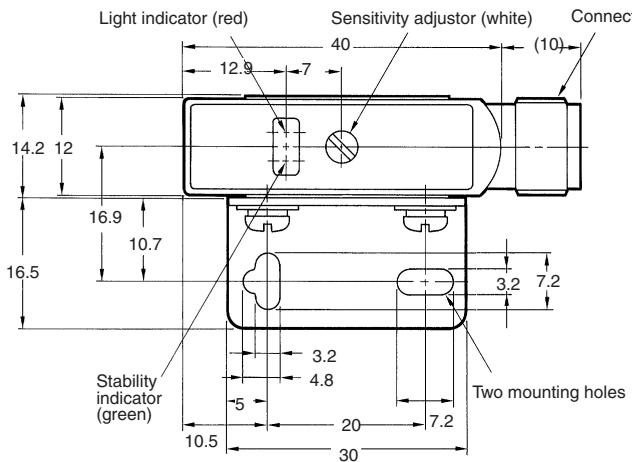
E3S-AD16. E3S-AD36
E3S-AD18, E3S-AD38
E3S-AD17, E3S-AD37
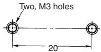
Mounting Holes
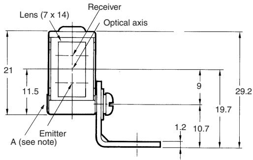
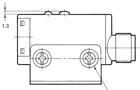
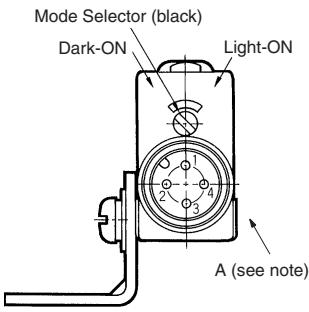
Two, M3 x 12 screws
Note: The mounting bracket can be attached to side A.
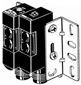
E3S-AT66, E3S-AT86 (Receiver)
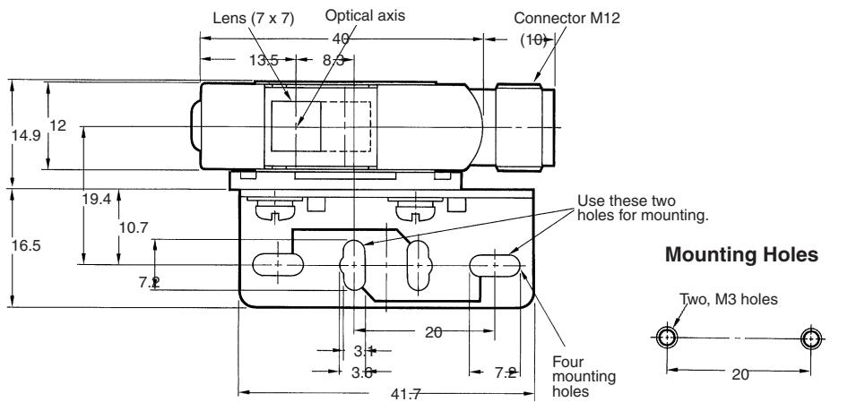
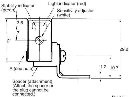
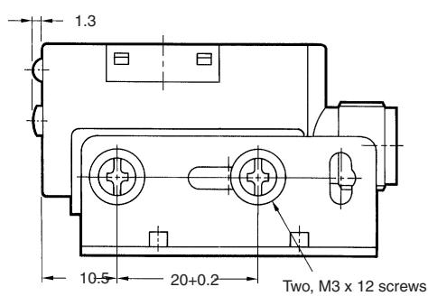
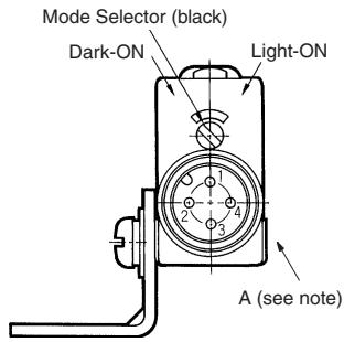
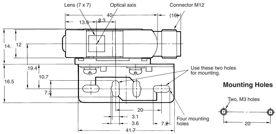
Note: The mounting bracket can be attached to side A.
E3S-AT66, E3S-AT86 (Emitter)
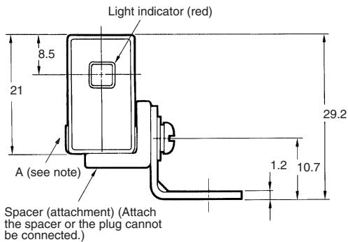
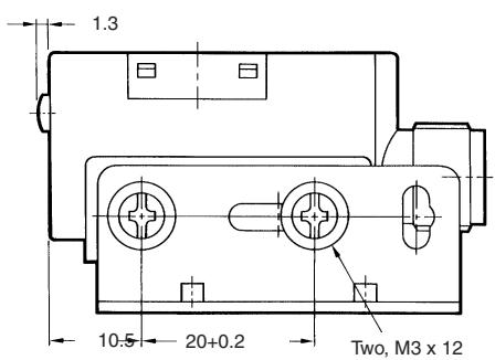
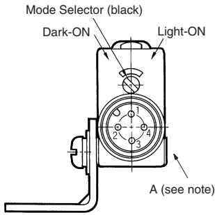
Note: The mounting bracket can be attached to side A.
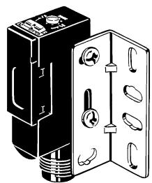
E3S-AR66, E3S-AR86
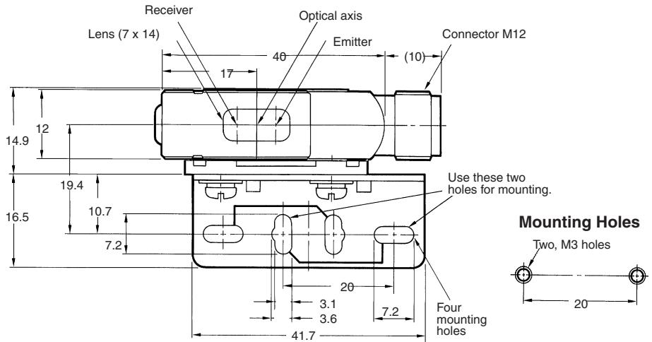
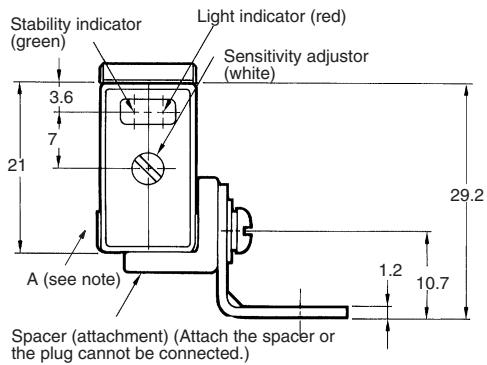
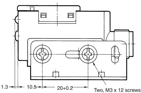

Note: The mounting bracket can be attached to side A.
E3S-AD66,E3S-AD86
E3S-AD68, E3S-AD88
E3S-AD67, E3S-AD87
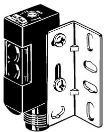
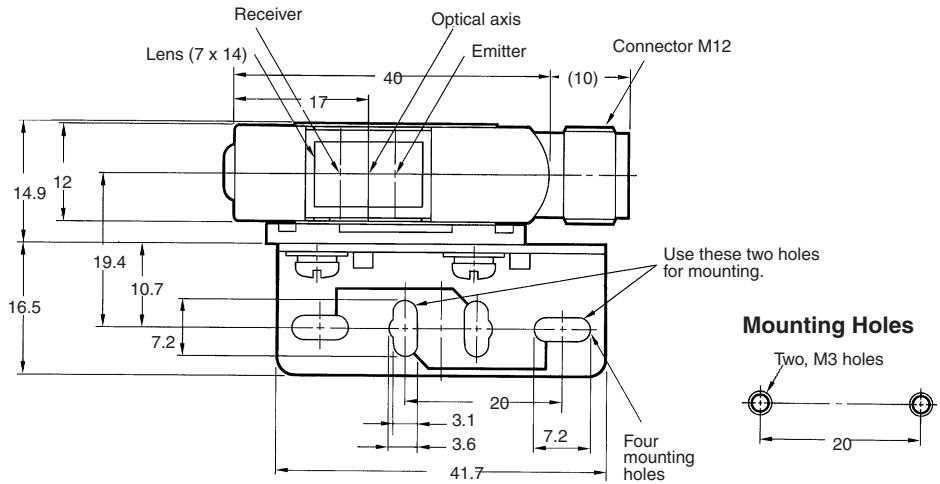
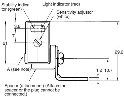
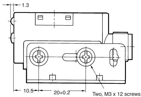
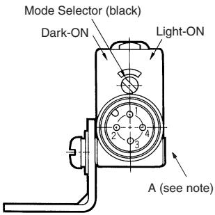
Note: The mounting bracket can be attached to side A.
Accessories
Plug (for E3S-A Connector type)
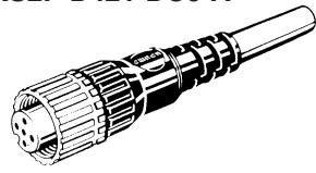
Straight Type
XS2F-D421-DC0-A
Polyvinyl chloride-covered cord, 0.5mm_2 (oilproof), 3 cores, Standard length: 2m
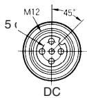
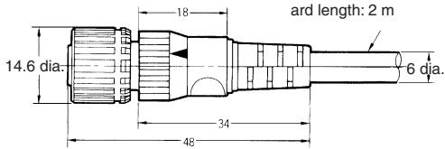
The XS2F-D421 Straight Cable Connector is also available. Refer to the output circuit diagram on page A-237.
| Cable drawing direction | No. of conductors | Cord length | Model |
| Straight | 3 | 2 m | XS2F-D421-DC0-A |
| 4 | XS2F-D421-D80-A | ||
| 3 | 5 m | XS2F-D421-GC0-A | |
| 4 | XS2F-D421-G80-A |
Attachments
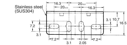
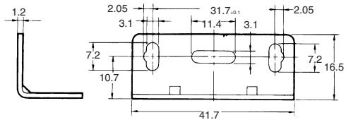
Standard Mounting Bracket (for E3S-A Horizontal Sensor) E39-L69
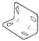
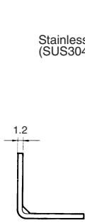
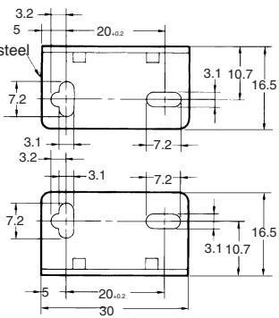
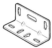
Standard Mounting Bracket (for E3S-A Vertical Sensor) E39-L70
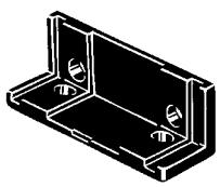
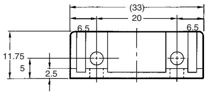
Close Mounting Plate (for E3S-A Connector Type) E39-L60
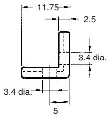
Sensitivity Adjustor Knob (for E3S-A) E39-G2
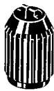
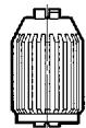
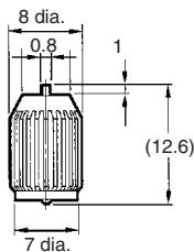

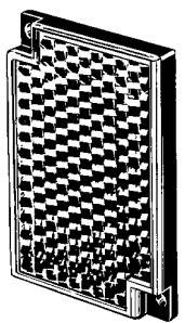
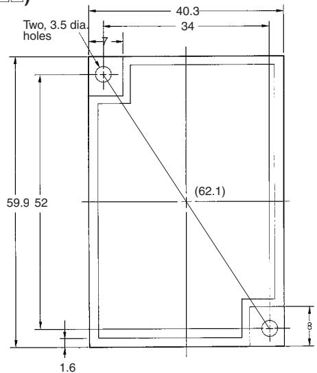
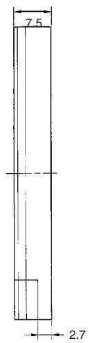
Retroreflector (Included with E3S-□R□□) E39-R1
Accessories (Order Separately)
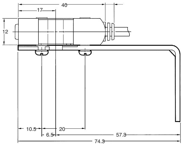
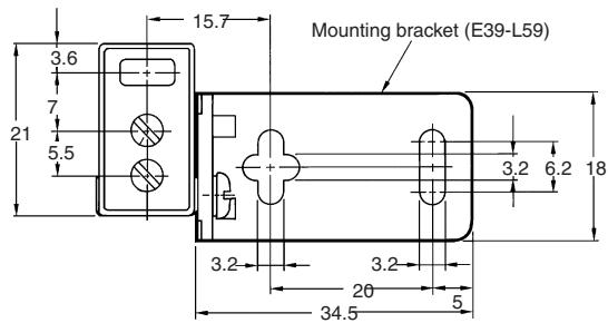
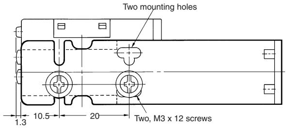
Vertical Mounting Bracket (for E3S-A) E39-L59
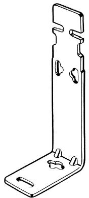
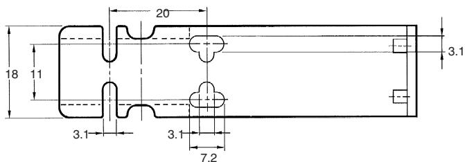
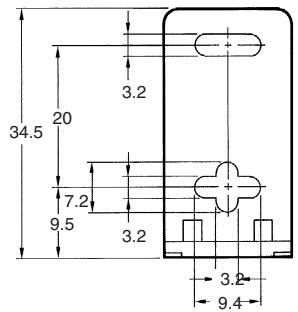
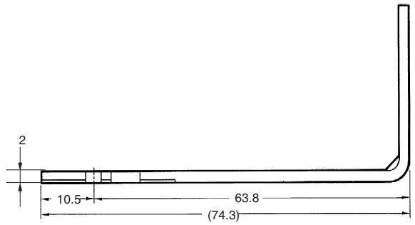
Mounting Example of E3S-A on E39-L59
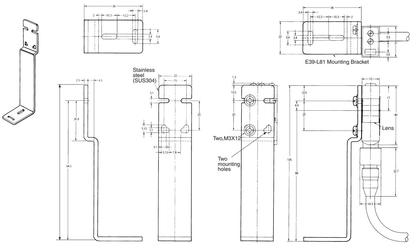
Mounting Example of E3S-A on E39-L81
Slit (for E3S-A) E39-S46
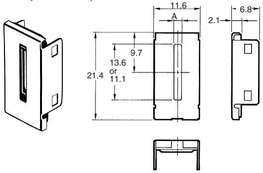
Note: The width of A is 0.5 mm,1 mm ,or 2 mm depending on the model.
Filters for Mutual Interference Prevention (for E3S-A)
E39-E6
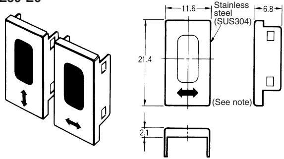
Note: Two vertical filters and two horizontal filters are sold together.
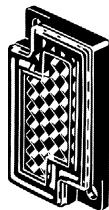
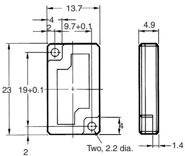
Mini-reflector E39-R4
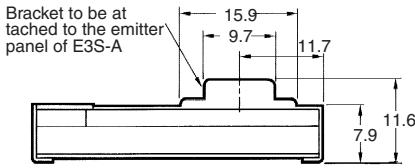
Optical Axis Confirmation Reflector (for E3S-A) E39-R5
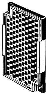
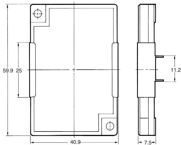
Small Reflector E39-R3
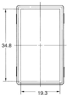
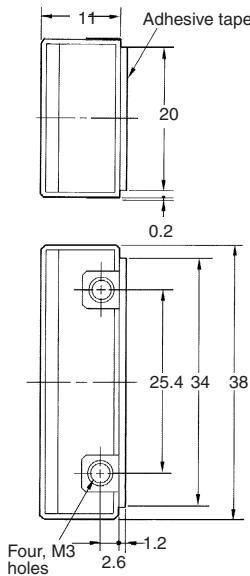
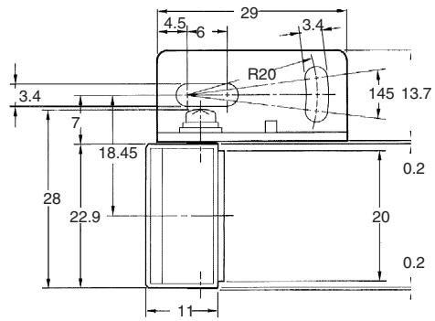
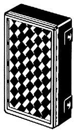
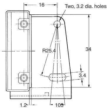
E39-R3 - With Enclosed Mounting Bracket
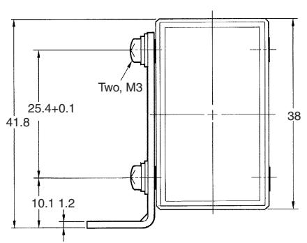
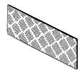
Reflecting Tape E39-RS1
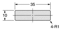
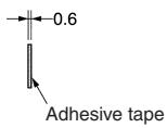

Reflecting Tape E39-RS2

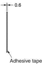
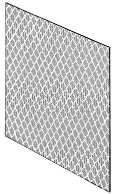
Reflecting Tape E39-RS3
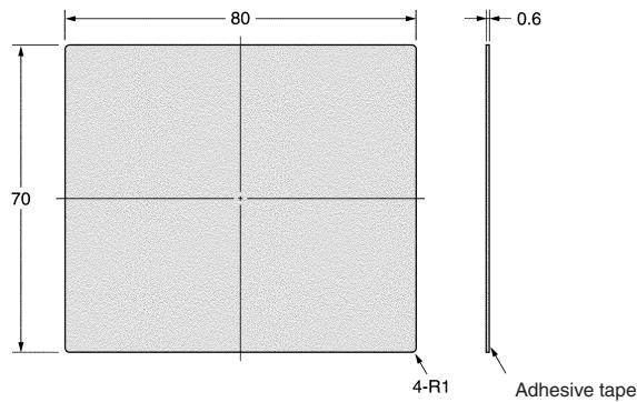
| Item | E39-R3 | E39-RS1 | E39-RS2 | E39-RS3 | E39-R4 |
| Directional angle | 30° min. | 2 to 20° | |||
| Ambient temperature | Operating: -25°C to 55°C Storage: -40°C to 70°C | Operating: -25°C to 55°C Storage: 0°C to 40°C | Operating: -25°C to 55°C Storage: -40°C to 70°C | ||
| Ambient humidity | Operating: 35% to 85% Storage: 35% to 95% | Operating: 35% to 85% Storage: 35% to 85% | Operating: 35% to 85% Storage: 35% to 95% | ||
| Enclosure rating | IP67 | ||||
Note: The above reflector tapes are polarizing.
Installation
Connections (Without Self-diagnostic Function)
Load (Relay)
| Sensing method | Through-beam | Retroreflective / diffuse reflective | |
| Connection method | *12 to 24 V 0 V Blue Emitter | **100 mA max. Load Receiver Black *12 to 24 V Brown Blue 0 V Blue | 0 V Blue *12 to 24 V Brown Load *100 mA max 100 V Output |
- 10 to 30 V for the E3S-A
If the load is a relay, insert a surge absorbing diode between the coils of the relay.
* The connection examples are for sensors with the NPN output.
With Sensor Controller S3D2
| Sensing method | Through-beam | Retroreflective / diffuse reflective |
| Connection method | Brown Emitter Receiver Blue Blue IN1 Black 12 V 0 V S3D2 | Brown Black Blue IN 1 V 0 V S3D2 |
Plug (for E3S-A with connector)
Internal Connection
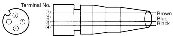
| Item | Color of cord | Connection pin No. | Application |
| For DC | Brown | 1 | Power supply (+V) |
| Black | 4 | Output | |
| Blue | 3 | Power supply (-V) |
Note: Pin No. 2 and 4 are connected internally.
External connection
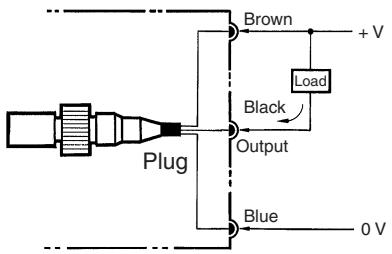
NPN Output
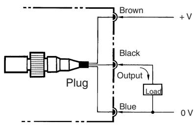
PNP Output
Tightening Plug
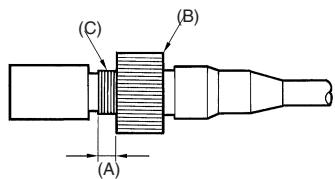
Turn part B by hand (do not use a pliers or the plug will be damaged) and tighten it with part C so that length A is nearly zero. Part B must be tightened properly with part C, or otherwise part B could be loosen by vibration and the sensor will not maintain the specified enclosure ratings.
Note: Use the spacer (sold together) to mount the photoelectric sensor with or without the enclosed mounting bracket (refer to Dimensions (page A-244)).
Precautions
The supplied voltage must be within the rated voltage range. Unregulated full-or half-wave rectifiers must not be used as power supplies.
If the input/output lines of the photoelectric sensor are placed in the same conduit or duct as power lines or high-voltage lines, the photoelectric sensor could be induced to malfunction, or even be damaged, by electrical noise. Either separate the wiring, or use shielded lines as input/output lines to the photoelectric sensor.
Do not use a hammer to hit the amplifier when mounting or the amplifier will loose watertightness.
Note the following when using the E39-R3, E39-RSA, or E39-RSB reflector (tape):
- Before applying adhesive tape to the reflector, make sure that the reflector is free from oil or dust, or otherwise the adhesive tape will not stick to the reflector properly.
- Do not cut the reflector or the reflector will loose watertightness.
- Do not press the reflector with a metal object or a nail, or otherwise the reflector will not function properly.
Position of Optical Axis of Through-beam Model
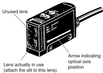
Unlike conventional through-beam models, the E3S Through-beam Photoelectric Sensor incorporates 2 lenses. But the lens actually in use is the one marked with an arrow indicating the position of the optical axis. When using a slit, attach it to the lens marked with the arrow.
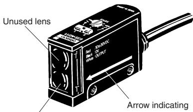
Lens actually in use
(attach the slit to this lens)
Arrow indicating
optical axis
position
Position of Arrow Indicating Optical Axis
| Model | Position of lens in use |
| E3S-A (vertical) | Top |
| E3S-A (horizontal) | Bottom |
Adjustor Cap
In order to prevent the sensitivity or OFF-delay time that has been set from changing accidentally enclosed, cover the adjustors with the adjustor cap (enclosed).
Mutual Interference Filter (E39-E6/-E8)
A set of 4 filters are sold together for two through-beam models (for 2 each of emitters and receivers).
For mounting, refer to the figure of the slit for the E3S-A Photoelectric Sensor.
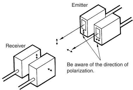
The arrow printed on the cover indicates the direction of polarization. By attaching the filters opposite to each other in polarization to the emitters and the receivers (refer to the figure) in rows, mutual interference can be prevented (in any case, the filter attached to an emitter and to the corresponding receiver must be the same in direction of polarization or the photoelectric sensor will not function).
Mounting Bracket
The direction of the optical axis coincides with the mounting direction of the E3S when the mounting screw is inserted into the lock hole of the mounting bracket. Unlike conventional photoelectric sensors, if the sensing object (or the retroreflector in the case of a through-beam sensor) is in the mounting direction of the photoelectric sensor, the object is detected with the incident light without the time-consuming adjustment of the optical axis (but if the mounting surface is not flat, the adjustment of the optical axis may still be required).
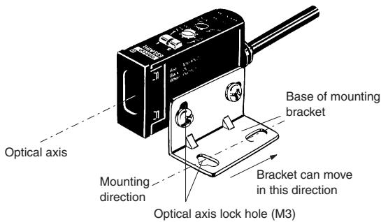
Note: The maximum tightening torque applied to the screw is 5.5kgf× cm (0.53 N x m).
Installation of Accessories
Sensitivity Adjustor Knob (Attachment)
To temporarily use the knob to adjust the sensitivity of the photoelectric sensor, insert side A into the shaft of the sensitivity adjustor.
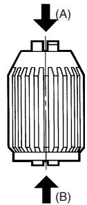
To permanently use the knob to adjust the sensitivity of the photoelectric sensor, insert side B into the shaft (the knob cannot be removed if once side B is inserted into the shaft).
Slit (E39-S46 Order Separately) for E3S-A
Use the rubber attachment with the metal cover if a slit width of 2mm is required. Insert the 0.5- or 1-mm slit between the metal cover and rubber attachment if a slit width of 0.5 or 1mm is desired. These slits fit into the rubber attachment.
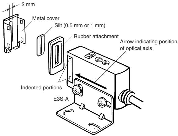
Note: Apply the slit to the lens of the photoelectric sensor marked with an arrow indicating the position of the optical axis (apply it to the bottom lens of horizontal sensors and the top lens of vertical sensors).
Optical Axis Reflector (E39-R5 Order Separately)
Use this attachment when the set distance is long and adjustment is mechanically difficult with a sensing object.
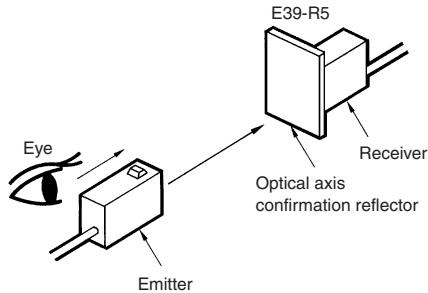
Attach the reflector to the receiver (refer to the figure).
Look at the reflector from right behind the emitter. The reflector should be bright with red light when the optical beam strikes the reflector. If the emitter has a turbo function, the reflector looks brighter with the function switched on.
When the reflector is removed, the light beam strikes the receiver.
ALL DIMENSIONS SHOWN ARE IN MILLIMETERS.
To convert millimeters into inches, multiply by 0.03937. To convert grams into ounces, multiply by 0.03527.
- Built-in Amplifier Photoelectric Sensor
- E3S-A
- Ordering Information
- Specifications
- Self-diagnostic Function
- External Diagnostic Input Function
- Timer and Turbo Switch (Sensors with Self-diagnostic Output Function)
- Turbo Function (Turbo Switch)
- With Turbo Switch ON
- Normal Operating Condition
- Operating Mode Selection
- Sensors
- Prewired Type
- Connector Type
- Accessories
- Plug (for E3S-A Connector type)
- Attachments
- Standard Mounting Bracket (for E3S-A Horizontal Sensor) E39-L69
- Standard Mounting Bracket (for E3S-A Vertical Sensor) E39-L70
- Close Mounting Plate (for E3S-A Connector Type) E39-L60
- Sensitivity Adjustor Knob (for E3S-A) E39-G2
- Installation
- Connections (Without Self-diagnostic Function)
- Plug (for E3S-A with connector)
- Internal Connection
- External connection
- Tightening Plug
- Precautions
- Position of Optical Axis of Through-beam Model
- Adjustor Cap
- Mutual Interference Filter (E39-E6/-E8)
- Mounting Bracket
- Installation of Accessories
- Sensitivity Adjustor Knob (Attachment)
- Slit (E39-S46 Order Separately) for E3S-A
- Optical Axis Reflector (E39-R5 Order Separately)
- Attach the reflector to the receiver (refer to the figure).
Marque : OMRON
Modèle : E3S-A
Catégorie : Capteurs de proximité