
E2KQ-X - Capteur de proximité OMRON - Notice d'utilisation et mode d'emploi gratuit
Retrouvez gratuitement la notice de l'appareil E2KQ-X OMRON au format PDF.


| Type de produit | Capteur de proximité inductif |
| Marque | OMRON |
| Modèle | E2KQ-X |
| Distance de détection | 10 mm (réglable 6 à 10 mm) |
| Objet de détection | Conducteurs et diélectriques |
| Type de sortie | DC 3 fils NPN (NO ou NC) |
| Tension d'alimentation | 12 à 24 VCC (10 à 30 VCC) |
| Consommation de courant | 15 mA max |
| Courant de commutation | 100 mA |
| Fréquence de réponse | 35 Hz |
| Indicateur de détection | LED rouge |
| Température ambiante | -10°C à 55°C |
| Humidité ambiante | 35% à 85% RH |
| Protection | IP66 |
| Matériau du boîtier | Résine fluorée (Téflon) |
| Poids | Environ 150 g |
| Dimensions (Diamètre x Longueur) | M18 x 61,8 mm |
| Raccordement | Câble pré-câblé 2 m |
| Accessoires fournis | Tournevis de réglage, écrous de serrage |
| Protections électriques | Inversion de polarité, absorbeur de surtension |
FOIRE AUX QUESTIONS - E2KQ-X OMRON
Questions des utilisateurs sur E2KQ-X OMRON
0 question sur cet appareil. Repondez a celles que vous connaissez ou posez la votre.
Poser une nouvelle question sur cet appareil
Téléchargez la notice de votre Capteur de proximité au format PDF gratuitement ! Retrouvez votre notice E2KQ-X - OMRON et reprennez votre appareil électronique en main. Sur cette page sont publiés tous les documents nécessaires à l'utilisation de votre appareil E2KQ-X de la marque OMRON.
MODE D'EMPLOI E2KQ-X OMRON
Inductive Proximity Sensor
E2KQ-X
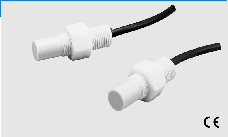
Proximity Sensor with Easy Sensing Distance Adjustment and Teflon* Coating Effective Oil and Chemical Resistance
- Oil and chemical-resistant Teflon case.
- Sensitivity adjuster ensures easy sensing distance adjustment according to the sensing object.
- Incorporates a cord connector with an indicator providing high visibility.
* Teflon is a registered trademark of Dupont Company and Mitsui Dupont Chemical Company for their fluoride resin.
natural_image
Two white plastic connectors with threaded ends, one black and one white, against a plain background (no text or symbols visible)Ordering Information
| Shape | Sensing distance | Output | Operating status | Model | |||
| Unshielded | M18 | 6 to 10 mm | DC 3-wire NPN | NO * | E2KQ-X10ME1 | ||
* NC models available (E2KQ-X10ME2)
Characteristic data (typical)
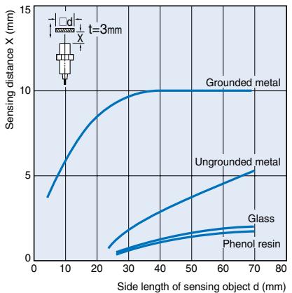
Sensing Distance vs. Sensing Object
line
| Side length of sensing object d (mm) | Grounded metal | Ungrounded metal | Glass | Phenol resin | | ------------------------------------ | -------------- | ---------------- | ----- | ------------ | | 0 | 3.5 | 0.5 | 0.5 | 0.5 | | 10 | 6.0 | 1.0 | 1.0 | 1.0 | | 20 | 8.0 | 1.5 | 1.5 | 1.5 | | 30 | 9.5 | 2.0 | 2.0 | 2.0 | | 40 | 10.0 | 2.5 | 2.5 | 2.5 | | 50 | 10.0 | 3.0 | 3.0 | 3.0 | | 60 | 10.0 | 3.5 | 3.5 | 3.5 | | 70 | 10.0 | 4.0 | 4.0 | 4.0 | | 80 | 10.0 | 4.5 | 4.5 | 4.5 |Sensing Object Thickness and Material vs. Sensing Distance
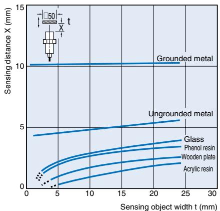
line
| Sensing object width t (mm) | Grounded metal | Ungrounded metal | | --------------------------- | -------------- | ----------------- | | 0 | 10 | 4 | | 5 | 10 | 2 | | 10 | 10 | 3 | | 15 | 10 | 4 | | 20 | 10 | 5 | | 25 | 10 | 6 | | 30 | 10 | 7 |DC 3-wire Models
| Operating status | Model | Timing chart | Output circuit |
| NO | E2KQ-X10ME1 |
Rating/Performance
| Item | Model | E2KQ-X |
| Sensing distance * | 10 mm | |
| Sensing distance adjustable range | 6 to 10 mm | |
| Differential distance | 4% to 20% of sensing distance | |
| Sensing object | Conductors and dielectrics | |
| Standard sensing object | with grounded metal: 50 x 50 x 1t mm | |
| Response frequency | 35 Hz | |
| Rated supply voltage (operating voltage) | 12 to 24 VDC (10 to 30 VDC), ripple (p-p): 10% max. | |
| Current consumption | 15 mA max. | |
| Control output | Switching capacity | 100 mA |
| Residual voltage | 1.5 V max. (under load current of 100 mA with cable length of 2 m) | |
| Indicator lamp | Detection indicator (red LED) | |
| Operating status (with sensing object approaching) | Refer to previous pages for details of operating chart of output circuits. | |
| Protective circuits | Reverse connection protection, surge absorber | |
| Ambient temperature | Operating: -10°C to 55°C, Storage: -25°C to 55°C (with no icing or condensation) | |
| Ambient humidity | Operating/Storage: 35% to 85%RH (with no condensation) | |
| Temperature influence | ±15% max. of sensing distance at 23°C in the temperature range of -10°C and 55°C | |
| Voltage influence | 2% max. sensing distance within a range of 80% to 120% of the rated supply voltage. | |
| Insulation resistance | 50 M min. (at 500 VDC) between energized parts and case | |
| Dielectric strength | 500 VAC 50/60 Hz for 1 min between energized part and case | |
| Vibration resistance | 10 to 55 Hz, 1.5 mm double amplitude for 2 hours each in X, Y, and Z directions | |
| Shock resistance | Destruction: 500 m/s2 for 3 times each in X, Y, and Z directions | |
| Protective structure | IEC IP66 | |
| Connection method | Pre-wired models (standard length: 2 m) | |
| Weight (Packed state) | Approx. 150 g | |
| Material | Case, Sensing surface | Fluororesin |
| Clamping nut | ||
| Accessories | Instruction sheet and screwdriver for adjustment | |
* This sensing distance is possible with a standard sensing object. Refer to Engineering Data for sensing distances of other materials.
Correct Use
Design
Effects of Surrounding Metals
If E2K-X is embedded in metal, maintain at least the following distances between E2K-X and the metal.
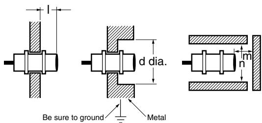
* Ensure to ground the metal object, otherwise E2KQ-X will not be in stable operation.
Effects of Surrounding Metal
(Unit: mm)
| Model\Length | l | d | m | n |
| E2KQ-X10ME1 | 30 | 75 | 18 | 90 |
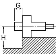
If a mounting bracket is used, be sure that at least the following distances are maintained.
Effects of Surrounding Metal
(Unit: mm)
| Model | Length | G | H |
| E2KQ-X10ME1 | 30 | 35 |
Mutual Interference
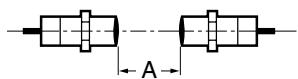
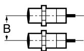
If more than one Sensor is located face to face or in parallel, provide sufficient space between adjacent Sensors to suppress mutual interference as indicated in the following diagram.
(Unit: mm)
Mutual Interference
| Model | Length | A | B |
| E2KQ-X10ME1 | 200 | 32 |
Effect of High-frequency Electro-magnetic Field
E2KQ-X may malfunction if there is an ultrasonic washer, high-frequency generator, transceiver, or inverter nearby. For a typical measure refer to the "Noise" with Common precautions of a photoelectric sensor in Rear B-page.
Installation
The tightening torque must not exceed the following value.
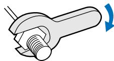
| Model | Tensile strength (torque) |
| E2KQ-X10ME1 | 0.6 Nm |
- Adjustment
Sensing object
The maximum sensing distance will decrease if the sensing object is a metal or dielectric object that is not grounded.
- Sensing Object Material E2K-C can detect almost any type of object. The sensing distance of E2K-C, however, will vary with the electrical characteristics of the object, such as the conductance and inductance of the object, and the water content and capacity of the object. The maximum sensing distance of E2K-C will be available if the object is made of grounded metal.
- Ensure a constant ambient operating temperature during the indirect detection of objects.
Miscellaneous
Ambient Conditions
Ensure that the E2K-X is free from sprayed water, oil, chemical, or condensation, otherwise E2K-X may malfunction by detecting them as sensing objects.
Environment
E2KQ-X has a water-resistant design. To increase the reliability of E2KQ-X in operation, however, it is recommended that E2KQ-X is free from sprayed water or machining oil.
The cord is not coated with Teflon, which must be taken into consideration when installing the E2KQ-X.
Dimensions
(Unit: mm)
E2KQ-X10ME1
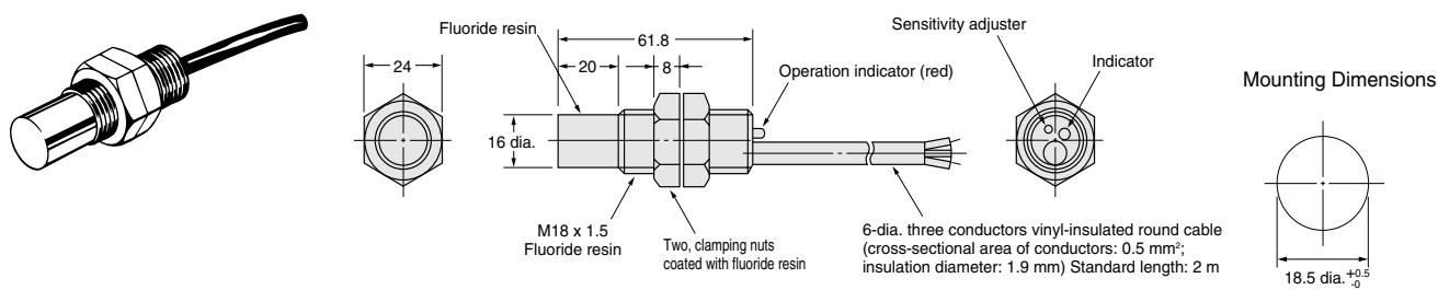
ALL DIMENSIONS SHOWN ARE IN MILLIMETERS.
To convert millimeters into inches, multiply by 0.03937. To convert grams into ounces, multiply by 0.03527.
Cat. No. D078-E2-02-X
In the interest of product improvement, specifications are subject to change without notice.
Marque : OMRON
Modèle : E2KQ-X
Catégorie : Capteur de proximité