
E3ZM-B - Capteur de proximité OMRON - Notice d'utilisation et mode d'emploi gratuit
Retrouvez gratuitement la notice de l'appareil E3ZM-B OMRON au format PDF.


| Type de produit | Capteur de proximité photodélectrique |
| Marque | OMRON |
| Modèle | E3ZM-B |
| Catégorie | Capteur de proximité |
| Distance de détection | 0 à 500 mm (avec réflecteur spécial) |
| Source lumineuse | LED rouge (650 nm) |
| Tension d'alimentation | 10 à 30 VCC (incluant 10% d'ondulation) |
| Consommation électrique max. | 450 mW (15 mA à 30 VCC) |
| Sortie de commande | Collecteur ouvert NPN ou PNP (selon modèle), 100 mA max. |
| Modes de fonctionnement | Light-ON / Dark-ON sélectionnable |
| Temps de réponse | 1 ms max. (marche ou arrêt) |
| Indicateurs | Marche (jaune), Stabilité (vert), Enseignement (rouge) |
| Matériau du boîtier | Inox SUS316L |
| Indice de protection | IP67 (IEC 60529), IP69K (DIN 40050-9) |
| Température ambiante (fonctionnement) | -40 à 60°C (modèles PET), -25 à 55°C (modèles tous matériaux) |
| Humidité ambiante (fonctionnement) | 35% à 85% HR (sans condensation) |
| Poids (version pré-câblée) | Environ 90 g |
| Poids (version connecteur) | Environ 40 g |
| Accessoires fournis | Notice d'instructions, réflecteur spécial E39-RP1 pour modèles -C |
| Entretien et nettoyage | Nettoyer avec un chiffon doux et sec. Ne pas utiliser de solvants organiques (alcool, diluant) ni de nettoyeur haute pression excessif. |
| Sécurité | Ne pas utiliser pour la sécurité des personnes. Respecter la tension nominale. Ne pas utiliser en atmosphère explosive. |
| Pièces détachées et réparabilité | L'appareil n'est pas réparable par l'utilisateur. Contacter votre représentant OMRON. |
FOIRE AUX QUESTIONS - E3ZM-B OMRON
Questions des utilisateurs sur E3ZM-B OMRON
0 question sur cet appareil. Repondez a celles que vous connaissez ou posez la votre.
Poser une nouvelle question sur cet appareil
Téléchargez la notice de votre Capteur de proximité au format PDF gratuitement ! Retrouvez votre notice E3ZM-B - OMRON et reprennez votre appareil électronique en main. Sur cette page sont publiés tous les documents nécessaires à l'utilisation de votre appareil E3ZM-B de la marque OMRON.
MODE D'EMPLOI E3ZM-B OMRON
Transparent object detection sensor in compact stainless steel housing
E3ZM-B
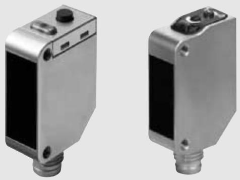
The E3ZM-B provides enhanced detection stability for the detection of transparent materials. The models for all transparent materials allow an easy and intuitive adjustment by potentiometer or teach button to adjust to individual requirements. The PET optimised model provides additional and auto-controlled measures for highest stability on PET materials.
- Easy adjustment to individual requirements for all transparent materials
- Stable PET detection with optimised detection settings and AC ^3 power control technology
• Detergent resistant compact SUS316L housing - Coaxial optics for stable, distance-independent detection
natural_image
Two metallic industrial sensors or modules with mounting holes, shown from different angles (no visible text or symbols)Ordering Information
| Sensor type | Sensing distance | Special reflector | Connection method | Order code | |||||
| *1 | NPN output | PNP output | |||||||
Retro-reflective with M.S.R. 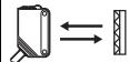 | Optimised for PET bottles and trays | 0 to 500 mm (teachable) | Order separately *2 | - | - | 2 m | - | E3ZM-B61 2M | E3ZM-B81 2M |
| ■ | - | - | - | E3ZM-B66 | E3ZM-B86 | ||||
| E39-RP1 included | - | - | 2 m | - | E3ZM-B61-C 2M | E3ZM-B81-C 2M | |||
| ■ | - | - | - | E3ZM-B66-C | E3ZM-B86-C | ||||
| For all transparent media (glass, PET, foils) | 0 to 500 mm (potentiometer adjustment) *3 | Order separately *4 | - | - | 2 m | - | E3ZM-B61T 2M | E3ZM-B81T 2M | |
| ■ | - | - | - | E3ZM-B66T | E3ZM-B86T | ||||
*1. For ordering pigtail versions contact your OMRON representative. Available options on request are:
- S1J: for M12 4-pin stainless steel plug with 30 cm cable
- S3J: for M8 4-pin stainless steel plug with 30 cm cable
- S5J: for M8 3-pin stainless steel plug with 30 cm cable (only E3ZM-B_T)
- M1J: for M12 4-pin brass plug with 30 cm cable
- M3J: for M8 4-pin brass plug with 30 cm cable
- M5J: for M8 3-pin brass plug with 30 cm cable (only E3ZM-B_T)
- M1TJ: for M12 4-pin brass XS5 click connector plug with 30 cm cable.
*2. For higher signal stability for PET bottles, order special reflector E39-RP1 separately.
*3. Teachable all-transparent-media types are available. Contact your OMRON representative.
*4. Order reflector separately.
Features
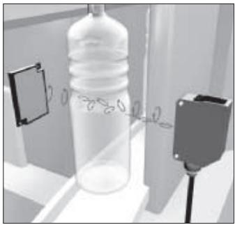
Enhanced detection stability on PET (PET optimised models)
natural_image
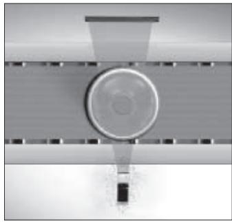
Illustration of a plastic bottle with liquid inside, connected to a sensor device (no text or symbols visible)Utilisation of double reflection effect in PET for higher detection stability (PET optimised models)
natural_image
Top-down view of a circular mechanical component with horizontal grooves and a central hub (no text or symbols visible)Automatic LED power adjustment (AC ^3 ) to compensate for soiling and temperature fluctuations
Robust housing and easy adjustment
natural_image
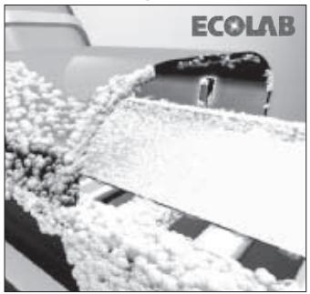
Industrial conveyor belt transporting white granular material, no visible text or symbols on the main subjectDetergent and high pressure water resistant (see page 9 for more info)
natural_image
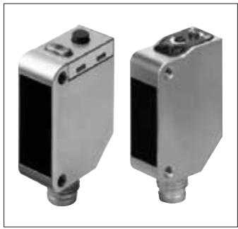
Two metallic industrial sensors or modules with mounting holes, shown from different angles (no visible text or symbols)Easy adjustment by potentiometer or teach button
Mounting Brackets
| Appearance | Model (Material) | Quantity | Remarks | Appearance | Model (Material) | Quantity | Remarks |
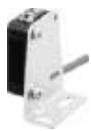 | E39-L104 (SUS304) | 1 | Standard surface mounting (pre-wired models) | 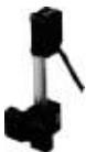 | E39-L150 (SUS304) | 1 set | Telescope mounting |
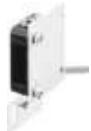 | E39-L43 (SUS304) | 1 | Protection wall mounting (pre-wired models) | 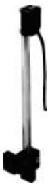 | E39-L151 (SUS304) | 1 set | |
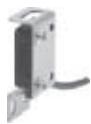 | E39-L142 (SUS304) | 1 | |||||
 | E39-L44 (SUS304) | 1 | Back wall mounting | 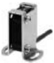 | E39-L144 (SUS304) | 1 | Protection surface mounting |
Note: for the complete range of mounting brackets refer to accessory datasheet E26E.
Cable connectors
For the complete list of cable connectors refer to E26E accessory datasheet.
| Size | Shape | Type | Features | Material | Order code | |||
| Nut | Cable | 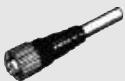 | 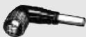 | |||||
| M8 | 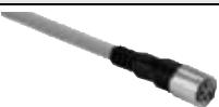 | General purpose (screw) | 4pin | Brass (CuZn) | PVC 2 m PUR 2 m | XS3F-M8PVC4S2M XS3F-M8PUR4S2M | XS3F-M8PVC4A2M XS3F-M8PUR4A2M | |
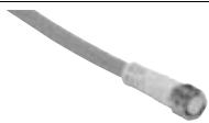 | Detergent resistant | Stainless steel (SUS316L) | PVC 2 m | Y92E-S08PVC4S2M-L | Y92E-S08PVC4A2M-L | |||
Reflectors
For the complete list of reflectors refer to E26E accessory datasheet.
| Shape | Type | Housing material | Features | Size in mm | Order code |
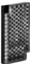 | General purpose reflectors | ABS base Acrylic surface | Surface screw mounting (diagonal holes) | 40x60x7.5 | E39-R1S |
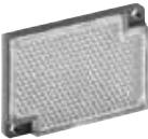 | Enhanced detergent resistance | PVC | Surface screw mounting IP69k after DIN 40050 part 9 | 40x60x7.5 | E39-R50 |
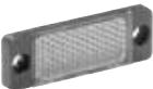 | 20x60x6 | E39-R51 | |||
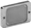 | Highest detergent resistance | SUS316L Borosilicat | Surface screw mounting | 43x30x5 | E39-R16 |
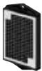 | Special polarizing | ABS base PMMA surface | Special polarizing filter for PET bottles - in combination with E3ZM-B models for PET only | 44x80x8.5 | E39-RP1 |
Ratings and Specifications
| Item | Optimised for PET | For all transparent objects | |
| E3ZM-B_ | E3ZM-B_T | ||
| Sensing distance | 0 to 500 mm (Using E39-RP1); min distance to reflector: 100 mm | ||
| Standard sensing object | 500-ml, transparent, round PET bottle (65-mm dia.) | ||
| Directional angle | Sensor: 3° to 10°Reflector: 30° | ||
| Light source (wavelength) | Red LED (650 nm) | ||
| Power supply voltage | 10 to 30 VDC, including 10% ripple (p-p) | ||
| Current consumption | 450 mW max. (15 mA at 30 VDC) | 25 mA max. | |
| Control output | Load power supply voltage: 30 VDC max., Load current: 100 mA max. (Residual voltage: 2 V max.)Open-collector output (NPN/PNP output depending on model) | ||
| Operating modes | Light-ON/Dark-ON selectable by wire | Light-ON/Dark-ON switch selectable | |
| Protective circuits | Reversed power supply polarity, load short-circuit protection, mutual interference prevention, reversed output polarity protection | ||
| Response time | Operation or reset: 1 ms max. | ||
| Sensitivity adjustment | Teach button | one-turn adjuster | |
| Ambient illumination | Incandescent lamp: 3,000 lx max., Sunlight: 10,000 lx max. | ||
| Ambient temperature range | Operating: -40 to 60°C (*1), Storage: -40 to 70°C (with no icing or condensation) | Operating: -25 to 55°CStorage: -40 to 70°C (with no icing or condensation) | |
| Ambient humidity range | Operating: 35% to 85%, Storage: 35% to 95% (with no condensation) | ||
| Insulation resistance | 20 MΩ min. at 500 VDC | ||
| Dielectric strength | 1,000 VAC, 50/60 Hz for 1 min | ||
| Vibration resistance | Destruction: 10 to 55 Hz, 1.5-mm double amplitude for 2 hours each in X, Y, and Z directions | ||
| Shock resistance | Destruction: 500 m/s2 3 times each in X, Y, and Z directions | ||
| Degree of protection | IEC 60529: IP67, DIN 40050-9: IP69K (*2) | ||
| Connection method | Pre-wired cable (standard length: 2 m) or M8 4-pin connector | ||
| Indicator | Operating indicator (yellow), Stability indicator (green), and Teaching indicator (red) | ||
| Weight (packed state) | Pre-wired models: Approx. 90 gConnector models: Approx. 40 g | ||
| Materials | Housing | SUS316L | |
| Lens | PMMA (polymethylmethacrylate) | ||
| Indicator | PES (polyethersulfone) | ||
| Buttons/adjusters | Fluoro rubber | PEEK (polyetheretherketone) | |
| Cable | PVC (polyvinyl chloride) | ||
| Accessories | Instruction sheet, (special reflector E39-RP1 for E3ZM-B_-C only)*4 | ||
*1. Do not bend the cable in temperatures of -25^ or lower.
*2. IP69K Degree of protection specification (for measures for improving the protection against water ingress see page 9).
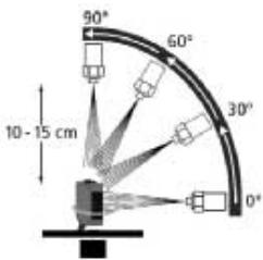
IP69K is a protection standard against high temperature and high-pressure water defined in the German standard DIN 40050, Part 9. The test piece is sprayed with water at 80^ at a water pressure of 80 to 100 BAR using a specified nozzle shape at a rate of 14 to 16 liters/min.
The distance between the test piece and nozzle is 10 to 15 cm, and water is sprayed horizontally for 30 seconds each at 0^ , 30^ , 60^ , and 90^ while rotating the test piece on a horizontal plane.
*4 For reflectors and mounting brackets refer to Accessories.
Parallel Operating Range (Horizontal)
E3ZM-B
(measured with E39-RP1)
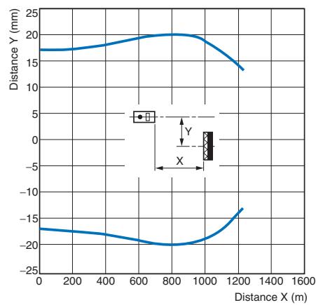
line
| Distance X (m) | Distance Y (mm) | | -------------- | --------------- | | 0 | 17 | | 200 | 17 | | 400 | 18 | | 600 | 19 | | 800 | 20 | | 1000 | 20 | | 1200 | 14 | | 1400 | -15 | | 1600 | -15 |Parallel Operating Range (Vertical)
E3ZM-B
(measured with E39-RP1)
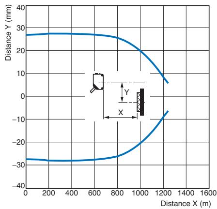
line
| Distance X (m) | Distance Y (mm) | | -------------- | --------------- | | 0 | -30 | | 200 | -30 | | 400 | -30 | | 600 | -30 | | 800 | -25 | | 1000 | -15 | | 1200 | 5 | | 1400 | 10 | | 1600 | 15 |Excess Gain vs. Distance
E3ZM-B
(measured with E39-RP1)
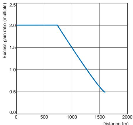
line
| Distance (m) | Excess gain ratio (multiple) | | ------------ | ---------------------------- | | 0 | 2.0 | | 750 | 2.0 | | 1600 | 0.5 |Note: The AC ^3 function controls the excess gain ratio to be a constant multiple of 2.
Dark Excess Gain vs. Sensing Object Characteristics (PET optimised models)
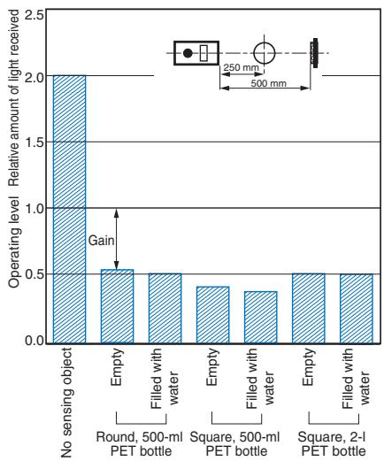
bar
| Category | Relative amount of light received | |---|---| | No sensing object | 2.0 | | Empty | 0.5 | | Filled with water | 0.5 | | Empty | 0.4 | | Filled with water | 0.35 | | Empty | 0.5 | | Filled with water | 0.5 |Dark Excess Gain vs. Position (PET optimised models)
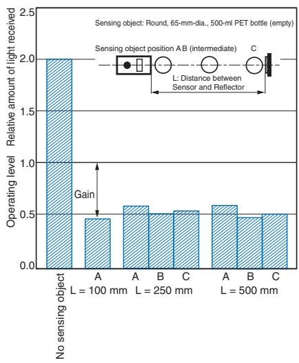
bar
| Sensing object | L (mm) | Relative amount of light received | | -------------- | ------ | --------------------------------- | | No sensing object | 100 | 2.0 | | A | 100 | 0.45 | | A | 250 | 0.58 | | B | 250 | 0.52 | | C | 250 | 0.53 | | A | 500 | 0.59 | | B | 500 | 0.47 | | C | 500 | 0.51 |PET optimised models
NPN Output
| Model | Operation mode | Timing charts | Operation selector | Output circuit |
| E3ZM-B61E3ZM-B66 | Light-ON | Light incidentLight interruptedOperation indicator ON(yellow)OFFOutput transistor ON(e.g., relay)ResetBetween brown (1)and black (4) leads | Connect pink lead (2) to brown lead (1). | 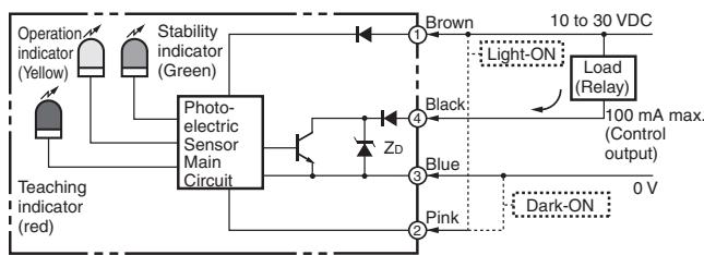 M8 ConnectorPin Arrangement 2 \\14 \\5 M8 ConnectorPin Arrangement 2 \\14 \\5 |
| Dark-ON | Light incidentLight interruptedOperation indicator ON(yellow)OFFOutput transistor ON(e.g., relay)ResetBetween brown (1)and black (4) leads | Connect pink lead (2) to blue lead (3) or leave open. |
All transparent material models
NPN Output
| Model | Operation mode | Timing charts | Operation selector | Output circuit |
| E3ZM-B61TE3ZM-B66T | Light-ON | Light incidentLight interruptedOperation indicator ON(yellow) OFFOutput transistor ONLoad (e.g., relay) Operate Reset Between brown (1) and black (4) leads | Set switch to L-ON | 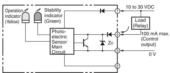 M8 Connector Pin Arrangement2413 M8 Connector Pin Arrangement2413 |
| Dark-ON | Light incidentLight interruptedOperation indicator ON(yellow) OFFOutput transistor ONLoad (e.g., relay) Operate Reset Between brown (1) and black (4) leads | Set switch to D-ON |
PET optimised models
PNP Output
| Model | Operation mode | Timing charts | Operation selector | Output circuit |
| E3ZM-B81E3ZM-B86 | Light-ON | Light incidentLight interruptedOperation indicator ON (yellow)OFFOutput transistor ONOFFLoad Operate (e.g., relay)ResetBetween blue (3) and black (4) leads | Connect pink lead (2) to brown lead (1). | 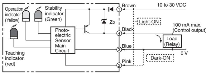 M8 Connector Pin Arrangement M8 Connector Pin Arrangement |
| Dark-ON | Light incidentLight interruptedOperation indicator ON (yellow)OFFOutput transistor ONOFFLoad Operate (e.g., relay)ResetBetween blue (3) and black (4) leads | Connect pink lead (2) to blue lead (3) or leave open. |
All transparent material models
PNP Output
| Model | Operation mode | Timing charts | Operation selector | Output circuit |
| E3ZM-B81TE3ZM-B86T | Light-ON | Light incident  Light interrupted — Operation indicator ON (yellow) OFF — Output transistor ON (e.g., relay) Offset and b [DT5Z6] Light interrupted — Operation indicator ON (yellow) OFF — Output transistor ON (e.g., relay) Offset and b [DT5Z6] | Set switch to L-ON | 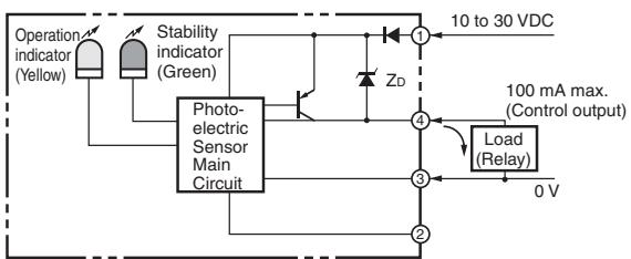 M8 Connector Pin Arrangement M8 Connector Pin Arrangement |
| Dark-ON | Light incident  Light interrupted — Operation indicator ON (yellow) OFF — Output transistor ON (e.g., relay) Offset and black (4) leads Light interrupted — Operation indicator ON (yellow) OFF — Output transistor ON (e.g., relay) Offset and black (4) leads | Set switch to D-ON |
Nomenclature
Models with teach button
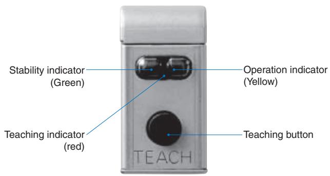
Models with potentiometer adjuster
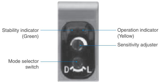
Teaching Method
(for models with teach-button)
Note: When the Sensor is first unpacked and used, the teaching indicator (red) will flash slowly to show that teaching has not yet been done. This does not indicate a malfunction. Use the following procedure to conduct teaching.
- Install the Sensor and Reflector and adjust the optical axis (without placing a PET bottle between them). Then press and hold the teaching button for at least 2 seconds.
The teaching indicator (red) will start flashing quickly.
Perform the following operation within 7 seconds after first starting to press the teaching button. (After 7 seconds, the Unit will return to its initial condition.)

Flashes quickly
- Press the teaching button again.
Teaching will then begin.
The teaching indicator will remain lit during the teaching operation.

Remains lit
When Teaching Is Successful
The teaching indicator (red) will go out. The Unit will then enter normal operating condition.
Dark-ON setting
Light-ON setting


When Teaching Is Not Successful
The teaching indicator (red) will flash slowly or quickly.
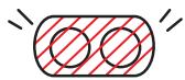
Flashes slowly or quickly
The teaching indicator (red) will then begin flashing even more slowly, indicating that the teaching operation should begin.
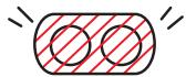
Flashes even more slowly
Repeat the operation starting with step 1.
Note: Depending on the amount of light received, the operation indicator and stability indicator may also change during the teaching operation.
Protective measures against aggressive chemicals
The E3ZM family of high grade stainless steel sensors has been designed with the goal to achieve long sensor lifetime in frequently cleaned environments.
High grade SUS 316L housings provide high resistance to aggressive chemicals but the lifetime of a sensor is not only determined by the case material. The design quality is determined by the resistance against detergents of the complete protective structure. When designing a sensor, potential weak points are the material selection and areas where 2 materials connect e.g. the lens, cable entry or the potentiometers. The materials and design structure for the E3ZM have been intensively researched and tested to provide high detergent resistance and sensor lifetime in daily operations compensating for mechanical and temperature stress, high pressure water and aggressive chemicals.
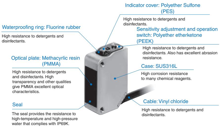
| Category | Product name | Concentration | Temper-ature | Time |
| Chemical | Sodium hydroxide (NaOH) | 1.5% | 70°C | 240 h |
| Potassium hydroxide (KOH) | 1.5% | 70°C | 240 h | |
| Phosphoric acid (H3PO4) | 2.5% | 70°C | 240 h | |
| Sodium hypochlorite (NaClO) | 0.3% | 25°C | 240 h | |
| Hydrogen peroxide (H2O2) | 6.5% | 25°C | 240 h | |
| Alkaline foam detergent | P3-topax-66s (Manufactured by Ecolab) | 3.0% | 70°C | 240 h |
| Acidic foam detergent | P3-topax-56 (Manufactured by Ecolab) | 5.0% | 70°C | 240 h |
| Disinfectant | P3-oxonia active 90 (Manufactured by Ecolab) | 1.0% | 25°C | 240 h |
| TEK121 (Manufactured by ABC Compounding) | 1.1% | 25°C | 240 h |
Note: The Sensor was immersed in the chemicals, detergents, and disinfectants listed above at the temperatures in the table for 240 hours and then passed an insulation resistance of 100 MΩ min.
Protective measures against water ingress
The family of E3ZM photoelectric sensors is designed and tested for highest protection against water ingress. For achieving the best protection in frequently cleaned environments and to prevent potential errors during installation and operation, refer to the recommendations below.
1. Using pre-wired models
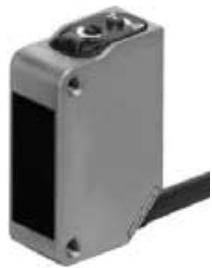
The pre-wired models are manufactured to provide highest protection against water ingress both at the sensor and via the cable.
RECOMMENDATION:
Use pre-wired versions if protection against water ingress is key and frequent replacement of the sensor is not expected
2. Using M8 connector models
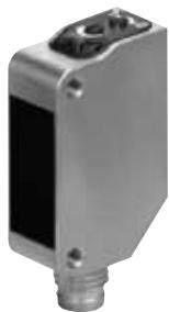
Connector models are often preferred to allow an easy exchange of the sensor. When using M8 connector models, observe the recommended mounting torque (see page 10). A too tight connection may damage the sealing ring and a loose connection may provide an opportunity for water to enter into the connection between sensor and connector.
RECOMMENDATION:
To obtain the correct mounting torque, a torque wrench may be used.
natural_image
Exterior view of a metallic industrial sensor or sensor device with mounting holes and a black cable (no visible text or symbols)Highest protection
natural_image
Metallic industrial sensor or sensor device with a black rectangular body and mounting holes (no visible text or symbols)Fast exchange
3. Using a M12 or M8 pigtail connector
Using a pigtail cable connector with 30 cm of PVC cable and an M8 or M12 plug combines the highest protection against water ingress of the pre-wired version with the flexibility of the connector models for easy exchanging the sensor.
In general the M12 connectors provide an enhanced protection against installation errors compared to M8 connectors. Additionally the XS5 click connectors always ensure that the correct tightening torque is applied for optimal protection.
RECOMMENDATION:
Use pigtail connectors for the best combination of protection and flexibility for exchanging the sensor.
For ordering pigtail connectors contact your OMRON representative.
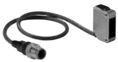

Highest protection and fast exchange
WARNING
This product is not designed or rated for directly or indirectly ensuring safety of persons. Do not use it for such a purpose.

CAUTION
Do not use the product with voltage in excess of the rated voltage. Excess voltage may result in malfunction or fire.

Never use the product with an AC power supply. Otherwise, explosion may result.

When cleaning the product, do not apply a high-pressure spray of water to one part of the product. Otherwise, parts may become damaged and the degree of protection may be degraded.

Precautions for Safe Use
The following precautions must be observed to ensure safe operation of the Sensor.
Operating Environment
Do not use the Sensor in an environment where explosive or flammable gas is present.
Connecting Connectors
Be sure to hold the connector cover when inserting or removing the connector.
When using an XS3F connector, be sure to tighten the connector lock by hand or preferably with a torque wrench; do not use other tools. If too much tightening torque is applied the degree of protection will not be maintained. If the tightening is insufficient, the degree of protection will not be maintained and the sensor may become loose due to vibration. The appropriate tightening torque is 0.3 to 0.4 N·m.
When using another, commercially available connector, follow the usage and tightening torque instructions provided by the manufacturer.
Load
Do not use a load that exceeds the rated load.
Low-temperature Environments
Do not touch the metal surface with your bare hands when the temperature is low. Touching the surface may result in a cold burn.
Oily Environments
Do not use the Sensor in oily environments. They may damage parts and reduce the degree of protection.
Modifications
Do not attempt to disassemble, repair, or modify the Sensor.
Outdoor Use
Do not use the Sensor in locations subject to direct sunlight.
Cleaning
Do not use thinner, alcohol, or other organic solvents. Otherwise, the optical properties and degree of protection may be degraded.
Cleaning
Do not use highly concentrated cleaning agents. Otherwise, malfunction may result. Also, do not use high-pressure water with a level of pressure that exceeds the stipulated level. Otherwise, the degree of protection may be reduced.
Surface Temperature
Burn injury may occur. The Sensor surface temperature rises depending on application conditions, such as the ambient temperature and the power supply voltage. Use caution when operating or performing maintenance on the Sensor.
Cable Bending
Do not bend the cable in temperatures of -25^ or below. Otherwise, the cable may be damaged.
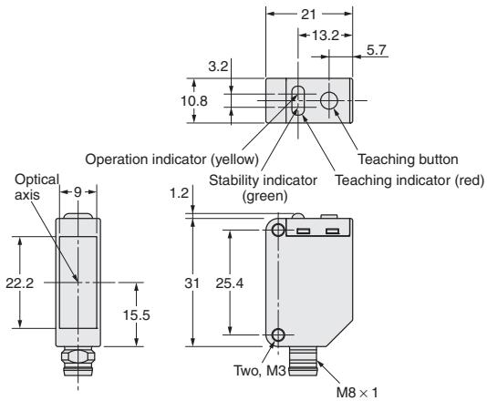
Dimensions
Note: All units are in millimeters unless otherwise indicated.
Sensors
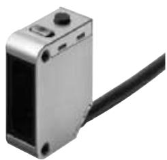
Pre-wired models
E3ZM-B61
E3ZM-B81
natural_image
Close-up of a metallic electronic device with a black cable extending from its side (no visible text or symbols)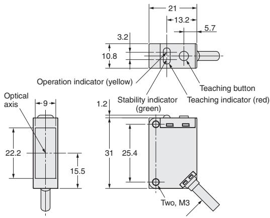
M12 Pre-wired Connector
(E3ZM-□□□-M1J
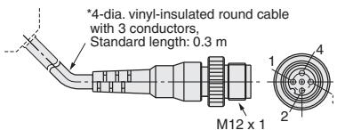
| Terminal No. | Specifications |
| 1 | +V |
| 2 | Operation selection |
| 3 | 0 V |
| 4 | Output |
4-dia. Vinyl-insulated round cable with 4 conductors
(Conductor cross section: 0.2 mm ^4 (AWG.24), Insulator diameter: 1.1 mm), Standard length: 2 m
E3ZM-B61T
E3ZM-B81T
natural_image
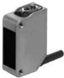
Exterior view of a metallic mechanical component with a black handle and mounting holes (no text or symbols visible)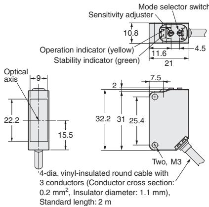
Exemplary pigtail connection
M12 pre-wired connector
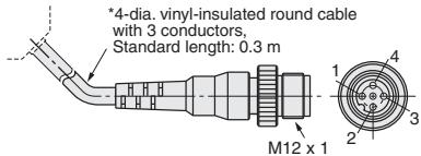
| Terminal No. | Specifications |
| 1 | +V |
| 2 | not connected |
| 3 | 0 V |
| 4 | Output |
M8 connector models
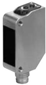
E3ZM-B66
E3ZM-B86
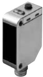

| Terminal No. | Specifications |
| 1 | +V |
| 2 | Operation selection |
| 3 | 0 V |
| 4 | Output |
E3ZM-B66T
E3ZM-B86T
natural_image
Metallic industrial sensor or probe device with mounting holes and a central button (no visible text or symbols)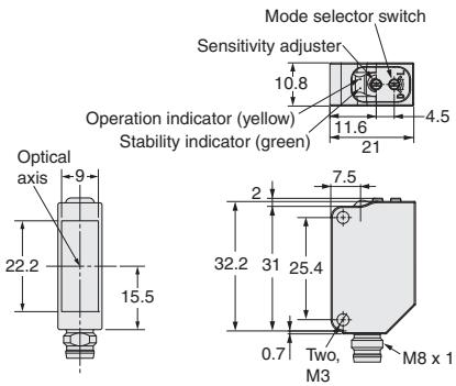

| Terminal No. | Specifications |
| 1 | +V |
| 2 | not connected |
| 3 | 0 V |
| 4 | Output |
WARRANTY
OMRON's exclusive warranty is that the products are free from defects in materials and workmanship for a period of one year (or other period if specified) from date of sale by OMRON.
OMRON MAKES NO WARRANTY OR REPRESENTATION, EXPRESS OR IMPLIED, REGARDING NON-INFRINGEMENT, MERCHANTABILITY, OR FITNESS FOR PARTICULAR PURPOSE OF THE PRODUCTS. ANY BUYER OR USER ACKNOWLEDGES THAT THE BUYER OR USER ALONE HAS DETERMINED THAT THE PRODUCTS WILL SUITABLY MEET THE REQUIREMENTS OF THEIR INTENDED USE. OMRON DISCLAIMS ALL OTHER WARRANTIES, EXPRESS OR IMPLIED.
LIMITATIONS OF LIABILITY
OMRON SHALL NOT BE RESPONSIBLE FOR SPECIAL, INDIRECT, OR CONSEQUENTIAL DAMAGES, LOSS OF PROFITS OR COMMERCIAL LOSS IN ANY WAY CONNECTED WITH THE PRODUCTS, WHETHER SUCH CLAIM IS BASED ON CONTRACT, WARRANTY, NEGLIGENCE, OR STRICT LIABILITY.
In no event shall responsibility of OMRON for any act exceed the individual price of the product on which liability is asserted.
IN NO EVENT SHALL OMRON BE RESPONSIBLE FOR WARRANTY, REPAIR, OR OTHER CLAIMS REGARDING THE PRODUCTS UNLESS OMRON'S ANALYSIS CONFIRMS THAT THE PRODUCTS WERE PROPERLY HANDLED, STORED, INSTALLED, AND MAINTAINED AND NOT SUBJECT TO CONTAMINATION, ABUSE, MISUSE, OR INAPPROPRIATE MODIFICATION OR REPAIR.
SUITABILITY FOR USE
THE PRODUCTS CONTAINED IN THIS DOCUMENT ARE NOT SAFETY RATED. THEY ARE NOT DESIGNED OR RATED FOR ENSURING SAFETY OF PERSONS, AND SHOULD NOT BE RELIED UPON AS A SAFETY COMPONENT OR PROTECTIVE DEVICE FOR SUCH PURPOSES. Please refer to separate catalogs for OM-RON's safety rated products.
OMRON shall not be responsible for conformity with any standards, codes, or regulations that apply to the combination of products in the customer's application or use of the product.
At the customer's request, OMRON will provide applicable third party certification documents identifying ratings and limitations of use that apply to the products. This information by itself is not sufficient for a complete determination of the suitability of the products in combination with the end product, machine, system, or other application or use.
The following are some examples of applications for which particular attention must be given. This is not intended to be an exhaustive list of all possible uses of the products, nor is it intended to imply that the uses listed may be suitable for the products:
- Outdoor use, uses involving potential chemical contamination or electrical interference, or conditions or uses not described in this document.
- Nuclear energy control systems, combustion systems, railroad systems, aviation systems, medical equipment, amusement machines, vehicles, safety equipment, and installations subject to separate industry or government regulations.
- Systems, machines, and equipment that could present a risk to life or property.
Please know and observe all prohibitions of use applicable to the products.
NEVER USE THE PRODUCTS FOR AN APPLICATION INVOLVING SERIOUS RISK TO LIFE OR PROPERTY WITHOUT ENSURING THAT THE SYSTEM AS A WHOLE HAS BEEN DESIGNED TO ADDRESS THE RISKS, AND THAT THE OMRON PRODUCT IS PROPERLY RATED AND INSTALLED FOR THE INTENDED USE WITHIN THE OVERALL EQUIPMENT OR SYSTEM.
PERFORMANCE DATA
Performance data given in this document is provided as a guide for the user in determining suitability and does not constitute a warranty. It may represent the result of OMRON's test conditions, and the users must correlate it to actual application requirements. Actual performance is subject to the OMRON Warranty and Limitations of Liability.
CHANGE IN SPECIFICATIONS
Product specifications and accessories may be changed at any time based on improvements and other reasons.
It is our practice to change model numbers when published ratings or features are changed, or when significant construction changes are made. However, some specifications of the product may be changed without any notice. When in doubt, special model numbers may be assigned to fix or establish key specifications for your application on your request. Please consult with your OMRON representative at any time to confirm actual specifications of purchased products.
DIMENSIONS AND WEIGHTS
Dimensions and weights are nominal and are not to be used for manufacturing purposes, even when tolerances are shown.
ERRORS AND OMISSIONS
The information in this document has been carefully checked and is believed to be accurate; however, no responsibility is assumed for clerical, typographical, or proofreading errors, or omissions.
PROGRAMMABLE PRODUCTS
OMRON shall not be responsible for the user's programming of a programmable product, or any consequence thereof.
Cat. No. E385-E2-01-X
In the interest of product improvement, specifications are subject to change without notice.
OMRON EUROPE B.V.
Wegalaan 67-69,
NL-2132 JD, Hoofddorp,
The Netherlands
Phone: +31 23 568 13 00
Fax: +31 23 568 13 88
www.industrial.omron.eu
- Transparent object detection sensor in compact stainless steel housing
- E3ZM-B
- Features
- Cable connectors
- Nomenclature
- Teaching Method
- Protective measures against aggressive chemicals
- Protective measures against water ingress
- Using pre-wired models
- RECOMMENDATION:
- Using M8 connector models
- Using a M12 or M8 pigtail connector
- WARNING
- CAUTION
- Precautions for Safe Use
- Operating Environment
- Connecting Connectors
- Load
- Low-temperature Environments
- Oily Environments
- Modifications
- Outdoor Use
- Cleaning
- Surface Temperature
- Cable Bending
- Dimensions
- Sensors
- WARRANTY
- LIMITATIONS OF LIABILITY
- SUITABILITY FOR USE
- PERFORMANCE DATA
- CHANGE IN SPECIFICATIONS
- DIMENSIONS AND WEIGHTS
- ERRORS AND OMISSIONS
- PROGRAMMABLE PRODUCTS
- OMRON EUROPE B.V.
Marque : OMRON
Modèle : E3ZM-B
Catégorie : Capteur de proximité