EMX5000 - Table de mixage numérique YAMAHA - Notice d'utilisation et mode d'emploi gratuit
Retrouvez gratuitement la notice de l'appareil EMX5000 YAMAHA au format PDF.
| Type de produit | Table de mixage numérique amplifiée |
| Marque | YAMAHA |
| Modèle | EMX5000-20 / EMX5000-12 |
| Canaux d'entrée | 16 mono (EMX5000-20) ou 8 mono (EMX5000-12) + 2 stéréo + 2 sous-entrées stéréo |
| Amplification intégrée | 2 canaux, puissance max 500 W + 500 W sous 4 Ω, sélectionnable (500/300/100 W) |
| Effets numériques | 2 processeurs multi-effets intégrés, 16 types chacun (dont TAP DELAY) |
| Égaliseur | 3 bandes par canal (High 10 kHz, Mid 250 Hz-5 kHz, Low 100 Hz) + Égaliseur graphique 9 bandes sur le bus ST |
| Alimentation fantôme | +48 V commutable par groupes de canaux (1-8 et 9-16 pour EMX5000-20, 1-8 pour EMX5000-12) |
| Connectique entrées | XLR et TRS symétriques (canaux mono), RCA stéréo (canaux stéréo, 2TR IN), Jack TRS (ST SUB IN) |
| Connectique sorties | Speakon (ENCEINTES 1), Jack 6,35 mm (ENCEINTES 2), Jack TRS (ST OUT, MONO OUT, AUX SEND, EFFECT SEND), RCA (REC OUT) |
| Écoute casque | Jack stéréo 6,35 mm avec volume réglable, pré-écoute PFL/AFL |
| Filtres | Filtre passe-haut 80 Hz par canal, filtre passe-bas réglable 80-120 Hz sur sortie MONO (pour subwoofer) |
| Technologie d'amplification | EEEngine (haute efficacité, consommation réduite de 50%, chaleur réduite de 35%) |
| Protections | Limiteur par ampli, indicateur de saturation, commutation de puissance max |
| Alimentation secteur | Cordon secteur détachable, mise à la terre obligatoire |
| Température de fonctionnement | Non spécifiée |
| Entretien | Nettoyer avec un chiffon sec et doux. Ne pas utiliser de solvants. |
| Sécurité | Ne pas ouvrir, éviter l'humidité, débrancher en cas d'orage, utiliser uniquement le cordon fourni |
FOIRE AUX QUESTIONS - EMX5000 YAMAHA
Questions des utilisateurs sur EMX5000 YAMAHA
0 question sur cet appareil. Repondez a celles que vous connaissez ou posez la votre.
Poser une nouvelle question sur cet appareil
Téléchargez la notice de votre Table de mixage numérique au format PDF gratuitement ! Retrouvez votre notice EMX5000 - YAMAHA et reprennez votre appareil électronique en main. Sur cette page sont publiés tous les documents nécessaires à l'utilisation de votre appareil EMX5000 de la marque YAMAHA.
MODE D'EMPLOI EMX5000 YAMAHA
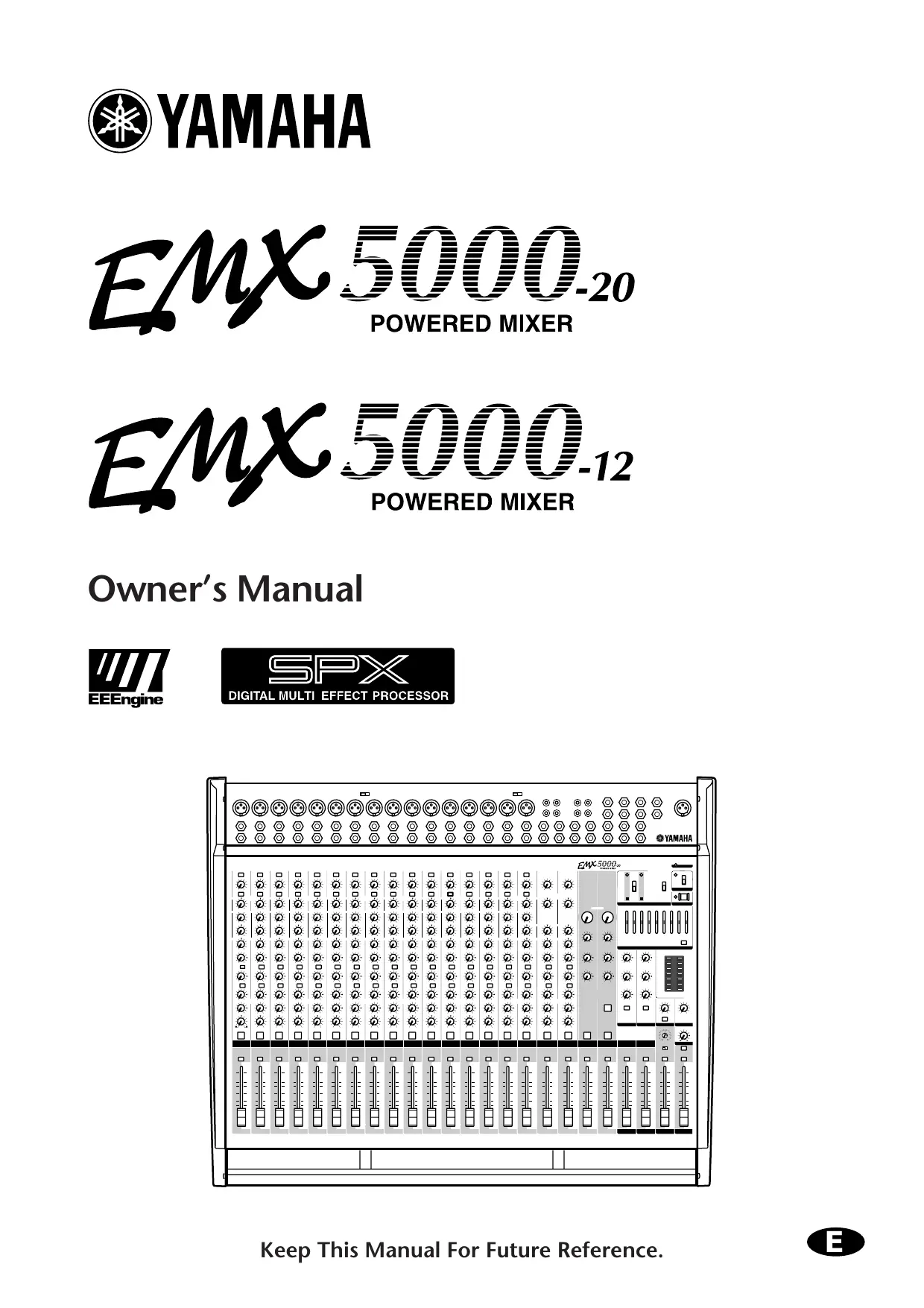
EMX 5000-20 POWERED MIXER
EMX 5000-12 POWERED MIXER
Owner's Manual


The Owner's Manual Revisions

Thank you for purchasing the Yamaha EMX5000-20/EMX5000-12 Powered Mixer. Parts of the EMX5000-20, EMX5000-12 owner's manual have been revised. Please refer to the following revisions rather than the corresponding sections of the original owner's manual.
P.14
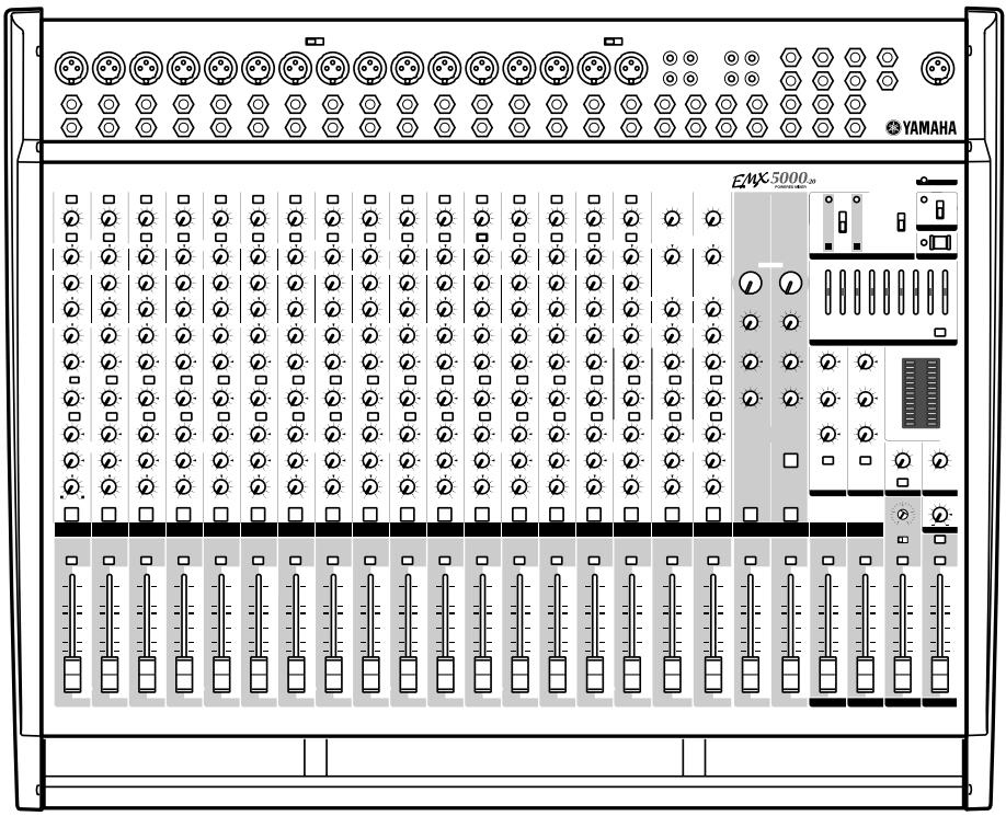
■ POWER amp section
34 LIMITER indicator
If the output level of signals received at the SPEAKERS jacks (output of the internal power amplifier) reaches maximum, the indicator will light.
Caution: If the LIMITER indicator flashes continuously, the internal power amplifier section is being excessively overloaded and may malfunction. Reduce the output level at the ST OUT fader (21) below the level that the indicator flashes only briefly on the highest transient peaks.
P.15
Other indicators and controls
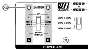
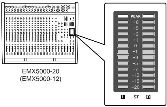
40 Level Meter
This LED display shows the level of signals received at the ST OUT jack (input/output panel 10).
Note: The SPEAKERS 1 & 2 jacks (rear panel ③ ) output the signals received at the ST OUT jack via the internal power amplifier. Check the output signal level via the LIMITER indicator ( ③ ). The LIMITER indicator will light before the Level Meter "8" or "PEAK" LED light.
P.18
Rear panel
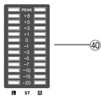
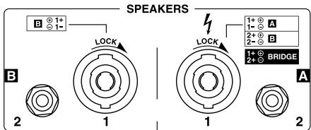
③ SPEAKERS (speaker output) jacks
These jacks are used to connect speakers.
Jacks 1 are Speakon-type connectors. Use only Neutrik NL4FC plugs for connecting Speakon connectors.
Jacks 2 are 1/4 phone jacks. The setting of the control panel power amp select switch ⑤ will determine the signal that is output to these jacks, and the number and appropriate impedance of the speakers that can be connected.
P.33
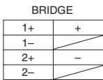
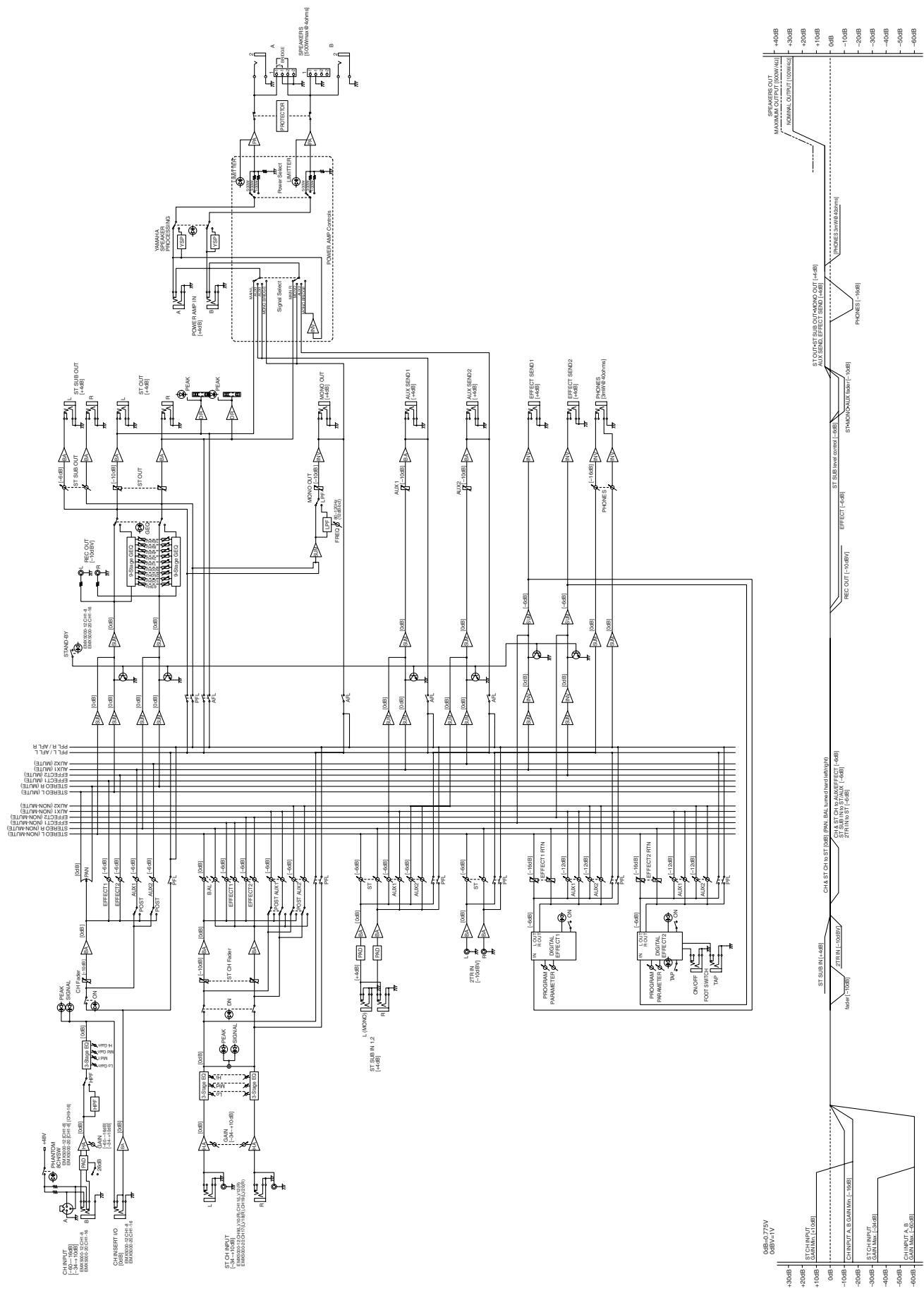
Block/Level Diagram
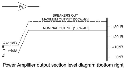
These plots show the nominal output and maximum output levels of signals received at the SPEAKERS jacks. If the output level is +4dB (Level Meter "0"), the internal power amplifier will deliver 100W into a 4 load. If the output level is +11dB (LIMITER indicator lights), the internal amplifier will deliver a maximum of 500W into 4 .
Block/Level Diagram
FCC INFORMATION (U.S.A.)
- IMPORTANT NOTICE: DO NOT MODIFY THIS UNIT! This product, when installed as indicated in the instructions contained in this manual, meets FCC requirements. Modifications not expressly approved by Yamaha may void your authority, granted by the FCC, to use the product.
- IMPORTANT: When connecting this product to accessories and/or another product use only high quality shielded cables. Cable/s supplied with this product MUST be used. Follow all installation instructions. Failure to follow instructions could void your FCC authorization to use this product in the USA.
- NOTE: This product has been tested and found to comply with the requirements listed in FCC Regulations, Part 15 for Class “B” digital devices. Compliance with these requirements provides a reasonable level of assurance that your use of this product in a residential environment will not result in harmful interference with other electronic devices. This equipment generates/uses radio frequencies and, if not installed and used according to the instructions found in the users manual, may cause interference harmful to the operation of other electronic devices. Compliance with FCC regulations does not guarantee that interference will not occur in all installations. If this product is found to be the source of interference, which can be determined by turning the unit “OFF” and “ON”, please try to eliminate the problem by using one of the following measures: Relocate either this product or the device that is being affected by the interference. Utilize power outlets that are on different branch (circuit breaker or fuse) circuits or install AC line filter/s. In the case of radio or TV interference, relocate/reorient the antenna. If the antenna lead-in is 300 ohm ribbon lead, change the lead-in to coaxial type cable. If these corrective measures do not produce satisfactory results, please contact the local retailer authorized to distribute this type of product. If you can not locate the appropriate retailer, please contact Yamaha Corporation of America, Electronic Service Division, 6600 Orangethorpe Ave, Buena Park, CA 90620
The above statements apply ONLY to those products distributed by Yamaha Corporation of America or its subsidiaries.

The above warning is located on the rear of the unit.
- Explanation of Graphical Symbols
The lightning flash with arrowhead symbol within an equilateral triangle is intended to alert the user to the presence of uninsulated "dangerous voltage" within the product's enclosure that may be of sufficient magnitude to constitute a risk of electric shock to persons.

The exclamation point within an equilateral triangle is intended to alert the user to the presence of important operating and maintenance (servicing) instructions in the literature accompanying the product.
WARNING: THIS APPARATUS MUST BE EARTHED
IMPORTANT
THE WIRES IN THIS MAINS LEAD ARE COLOURED IN ACCORDANCE WITH THE FOLLOWING CODE:
GREEN-AND-YELLOW: EARTH
BLUE: NEUTRAL
BROWN: LIVE
As the colours of the wires in the mains lead of this apparatus may not correspond with the coloured markings identifying the terminals in your plug, proceed as follows:
The wire which is coloured GREEN and YELLOW must be connected to the terminal in the plug which is marked by the letter E or by the safety earth symbol 1一 or coloured GREEN and YELLOW.
The wire which is coloured BLUE must be connected to the terminal which is marked with the letter N or coloured BLACK.
The wire which is coloured BROWN must be connected to the terminal which is marked with the letter L or coloured RED.
European Specifications Only
This mark indicates a dangerous electrically live terminal. When connecting an external wire to this terminal, it is necessary either to have "a person who have received appropriate guidance on handling" make the connection or to use leads or a cord that have been manufactured in such a way that the connection can be made simply and without problem.
Precautions
WARNING
Installation
- Connect this unit's power cord only to an AC outlet of the type stated in this Owner's Manual or as marked on the unit. Failure to do so is a fire and electrical shock hazard.
- Do not allow water to enter this unit or allow the unit to become wet. Fire or electrical shock may result.
- Do not place a container with liquid or small metal objects on top of this unit. Liquid or metal objects inside this unit are a fire and electrical shock hazard.
- Do not place heavy objects, including this unit, on top of the power cord. A damaged power cord is a fire and electrical shock hazard. In particular, be careful not to place heavy objects on a power cord covered by a carpet.
- Use only the included power cord for this unit. Using other types may be a fire and electrical shock hazard.
- The power to this device is not completely shut off even when the power switch is turned off. Locate the device close to the AC outlet so you can easily reach the power plug.
Operation
- Do not scratch, bend, twist, pull, or heat the power cord. A damaged power cord is a fire and electrical shock hazard.
- Do not remove the unit's cover. You could receive an electrical shock. If you think internal inspection, maintenance, or repair is necessary, contact your dealer.
- Do not modify the unit. Doing so is a fire and electrical shock hazard.
- If lightning begins to occur, turn off the power switch of the unit as soon as possible, and unplug the power cable plug from the electrical outlet.
- If there is a possibility of lightning, do not touch the power cable plug if it is still connected. Doing so may be an electrical shock hazard.
In case an abnormality occurs during operation
- If the power cord is damaged (i.e., cut or a bare wire is exposed), ask your dealer for a replacement. Using the unit with a damaged power cord is a fire and electrical shock hazard.
- Should this unit be dropped or the cabinet be damaged, turn the power switch off, remove the power plug from the AC outlet, and contact your dealer. If you continue using the unit without heeding this instruction, fire or electrical shock may result.
- If you notice any abnormality, such as smoke, odor, or noise, or if a foreign object or liquid gets inside the unit, turn it off immediately. Remove the power cord from the AC outlet. Consult your dealer for repair. Using the unit in this condition is a fire and electrical shock hazard.
CAUTION
Installation
- Keep this unit away from the following locations:
- Locations exposed to oil splashes or steam, such as near cooking stoves, humidifiers, etc.
- Unstable surfaces, such as a wobbly table or slope.
- Locations exposed to excessive heat, such as inside a car with all the windows closed, or places that receive direct sunlight.
- Locations subject to excessive humidity or dust accumulation.
- Hold the power cord plug when disconnecting it from an AC outlet. Never pull the cord. A damaged power cord is a potential fire and electrical shock hazard.
- Do not touch the power plug with wet hands. Doing so is a potential electrical shock hazard.
- This unit has ventilation holes at the rear to prevent the internal temperature rising too high. Do not block them. Blocked ventilation holes are a fire hazard.
- To relocate the unit, turn the power switch off, remove the power plug from the AC outlet, and remove all connecting cables. Damaged cables may cause fire or electrical shock.
Operation
- Turn off all musical instruments, audio equipment, and speakers when connecting to this unit. Use the correct connecting cables and connect as specified.
- Always lower the volume control to minimum before turning on the power to this unit. A sudden blast of sound may damage your hearing.
- Use only speaker cables when connecting speakers to amplifier outputs. Using other types of cables is a fire hazard.
- If you know you will not use this unit for a long period of time, such as when going on vacation, remove the power plug from the AC outlet. Leaving it connected is a potential fire hazard.
Maintenance
- Clean the contacts of the phone plug before connecting it to the SPEAKERS jack of this unit. Dirty contacts may generate heat.
- To prevent electrical shock when cleaning the unit, remove the power plug from the AC outlet.
PRECAUTIONS FOR OPERATION
FOR CORRECT OPERATION
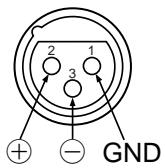
Connector pin assignments
- XLR-type connectors are wired as follows: pin 1: ground, pin 2: hot (+), and pin 3: cold (-).
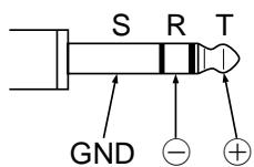
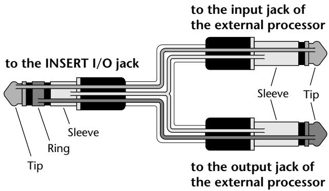
- Insert TRS phone jacks are wired as follows: sleeve: ground, tip: send, and ring: return.
Replacing abrasive parts
- The performance of components with moving contacts, such switches, rotary controls, faders, and connectors, deteriorates over time. The rate of deterioration depends on the operating environment and is unavoidable. Consult your dealer about replacing defective components.
Influence on cell phone usage
- Using a cell phone (mobile telephone) near this unit may induce noise. If noise occurs, use the telephone away from the unit.
Volume level setting
- Do not set all equalizer controls and faders to maximum. Doing so may cause oscillation depending on the condition of the connected unit and speakers, and may damage the speakers.
Interference with other electronic devices
- The digital circuits of this unit may induce a slight noise into nearby radios and TVs. If noise occurs, relocate the affected equipment.
Introduction
Thank you for purchasing the Yamaha EMX5000-20/EMX5000-12 Powered Mixer. In order to take full advantage of the EMX5000-20/EMX5000-12 and enjoy long, trouble-free performance, please read this owner's manual carefully, and keep it in a safe place for future reference.
Features
- The EMX5000-20/EMX5000-12 provides versatile inputs, such as two stereo input channels and two stereo sub inputs, as well as 16 (EMX5000-20), 8 (EMX5000-12) monaural input channels compatible with mic/line signals. The mixer also has ample power, with a maximum output of 500W + 500W (1000 W with bridge connection), and is suitable for a wide range of applications from installed systems to small-scale PA systems.
- A two-channel power amp is built-in. The signals output to speakers can be selected as stereo (ST L-R), AUX+monaural (AUX 1-MONO), two AUX (AUX1-AUX2) or monaural (bridge connection).
- In addition to the speaker output jacks, two stereo output channels for line-level signals, two AUX output channels, two effect outputs, and one monaural output are provided. You can easily expand the system by adding a power amplifier or powered speakers.
- The EMX5000-20/EMX5000-12 also has a PHONES jack, which is very useful for checking the sound. You can monitor only a specific channel or bus signal through the headphones.
Each amp contains a limiter circuit to prevent distortion due to excessive input levels. - A maximum output select switch lets you switch the maximum output of the amp between three levels. This lets you adjust the maximum output of the internal power amp as appropriate for the size of the room or the input capacity of the speakers.
- Two multi-effect units are built-in, each providing sixteen types of effect equivalent in quality to the acclaimed Yamaha SPX series of multi-effect units. The effects can be used to add reverb or ambience to vocals or instruments. The sixteen types (provided by each of the two effect units) include TAP DELAY, which lets you easily adjust the delay time.
- The EMX5000-20/EMX5000-12 has implemented "EEEngine", Yamaha's epochal amp drive technology to create an unrivaled high-efficiency drive. The EEEngine's energy-saver/low-heat-generation design has reduced power consumption to 50% or less, and reduced heat generation to 35% or less (in field applications, compared to Yamaha's previous models), and has lead to a reduction in energy cost and to less-restrictive installation requirements related to heat generation.
Contents
Introduction. 5
Features 5
EMX5000-20/EMX5000-12 Quick Guide 6
Front and rear panel. 10
Control panel 10
Input/output panel. 16
Rear panel 18
Installation/Connections 19
Installation 19
Connection 19
Connecting input/output equipment. 21
Basic operation 22
Connecting microphones and instruments 22
Using the digital effect 22
Example setups. 24
As a conference/entertainment hall sound system 24
As a band PA. 26
Using a subwoofer 28
Troubleshooting 29
Specifications 30
General specifications 30
Input specifications 31
Output specifications 31
Dimensions 32
Installing an optional rack mount kit 32
Block/Level Diagram 33
EMX5000-20/ EMX5000-12 Quick Guide
The following steps (1-5) explain the basic connection and operation of the EMX5000-20/ EMX5000-12.
Also, please read "Front and Rear Panel" and "Basic Operation" following this Quick Guide section to learn more about using the EMX5000-20/EMX5000-12.
STEP1 Connection
Connecting speakers
Using speaker cables, connect each speaker to the SPEAKERS A jack and to the B jack in the SPEAKERS jack section on the rear panel of the EMX5000-20/EMX5000-12.
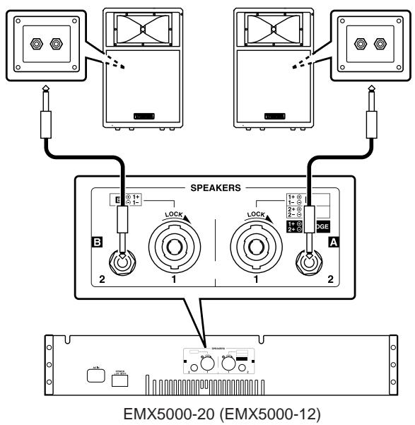
- In the example shown by the above diagram, two main speakers are connected (one each to left and right) in stereo. For other connection examples, refer to pages 20-21.
- You may connect to either of the two jacks on the speakers.
- Be sure to use a cable designed for speaker connection.
- Speakers with a Speakon connector can also be connected using a Speakon cable. In this case, use the SPEAKERS 1 jacks to output the signal from the EMX5000-20/EMX5000-12.
- When connecting a Speakon connector to the EMX5000-20/EMX5000-12, be sure to turn the plug to the right to lock the connection after inserting the plug.
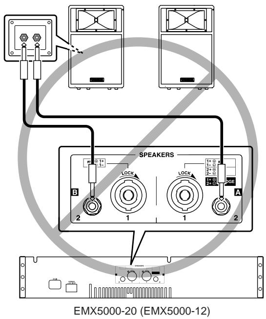
Never connect the speakers in the manner shown below. Otherwise, the EMX5000-20/EMX5000-12's built-in power amplifier will be damaged.
Setting the power amplifier mode
Set the power amp select switch (located on the right corner on the panel) to ST L-R.
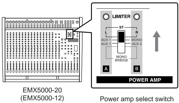
- This quick guide explains how to connect one main speaker each to left and right for stereo operation. If the power amp select switch is set to the ST L-R position as shown here, the stereo R signal will be output from the SPEAKERS A jacks, and the stereo L signal from the SPEAKERS B jacks. Refer to pages 14, 19, 20 for other connections and power amp select switch settings.
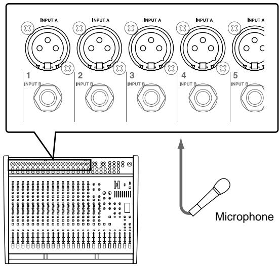
Connecting a microphone
Make sure that the power is turned off to the EMX5000-20/EMX5000-12.
Connect mics to channels 1-16 (EMX5000-20) or 1-8 (EMX5000-12), using the INPUT A jacks if the mic has an XLR plug, or the INPUT B jacks if the mic has a phone plug.
EMX5000-20 (EMX5000-12)
Using a condenser microphone
Turn on the PHANTOM switch (located in the upper center corner on the panel).
- The PHANTOM switch supplies phantom power to all channel inputs at once (EMX5000-20: 1-8 and 9-16, EMX5000-12: 1-8), so mics other than condenser mics must be connected to the INPUT B jacks.
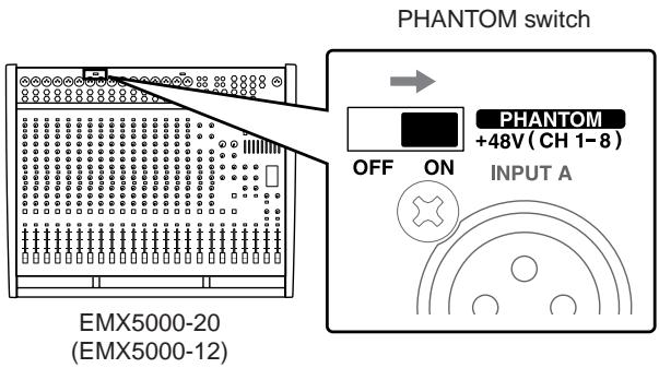
- Do not connect or disconnect a condenser microphone while the power to the unit is on and the PHANTOM switch has been turned on.
Connecting a CD player, MD player, and/or cassette deck
Connect a CD player or MD player to the 2TR IN jacks. Refer to the operation manual of the corresponding device for more information on the input and output of the device.
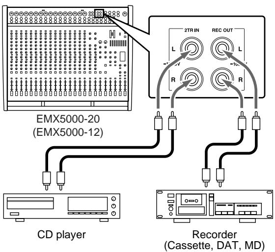
- To connect a second player, use the LINE jack.
- Connect a recorder to the REC OUT jacks.
Connecting an electric acoustic guitar or electric bass
Connect electric/acoustic guitars or electric basses via an effect processor or direct box to the INPUT B jack.
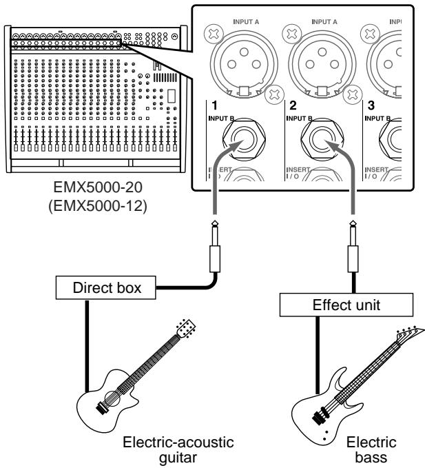
- You cannot use the INPUT A jack and the INPUT B jack for the same channel at the same time. If a microphone has already been connected to the INPUT B jack of a channel, you cannot connect the effect unit to the INPUT A jack of the channel.
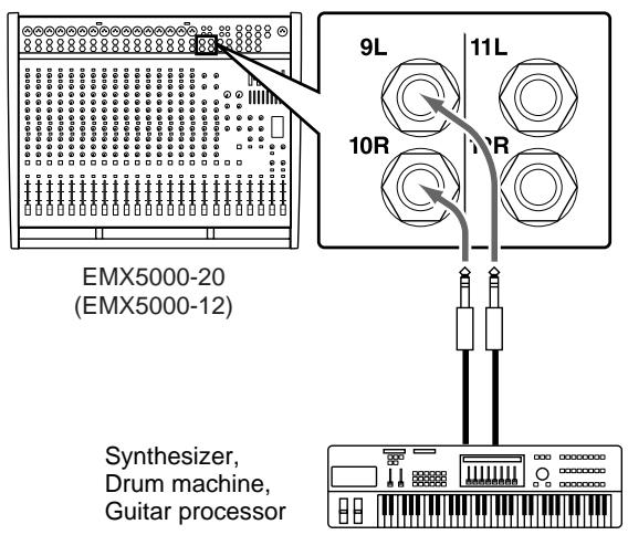
Connecting an electronic musical instrument
To the EMX5000-20/EMX5000-12's LINE or ST SUB IN jacks, you can connect an electronic musical instrument such as a synthesizer, drum machine, signal processor connected to an electric guitar, etc. Refer to the diagram below to make a stereo connection from the output jacks (such as L/MONO and R) of an electronic musical instrument to the LINE or ST SUB IN jacks in stereo.
STEP 2 Power on
1 Turn on the power to all external devices connected to the EMX5000-20/EMX5000-12.
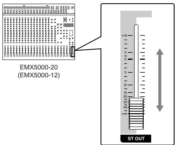
2 Make sure that the ST OUT fader of the EMX5000-20/EMX5000-12 is lowered, and then press the POWER switch of the EMX5000-20/ EMX5000-12 to turn it on.
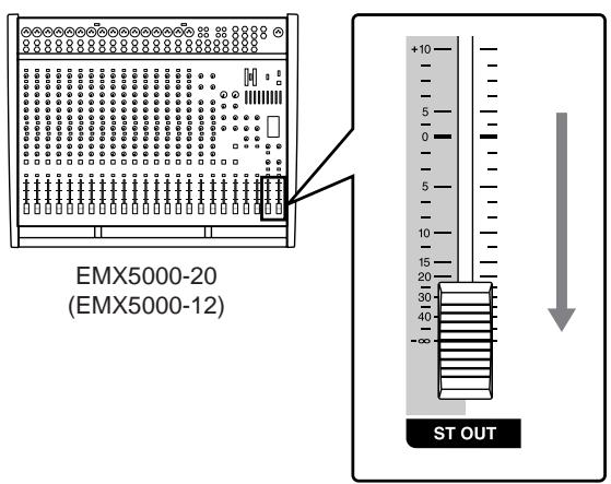
- Be sure to follow the power up sequence specified above to prevent the speakers from being damaged.
- To correct the low range, turn on the YAMAHA SPEAKER PROCESSING switch in the upper right corner of the panel.
STEP3 Sound output
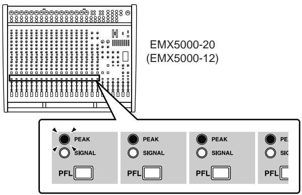
Set the ST OUT fader and the input channel faders to the “ - ” position, and while playing the instrument (or singing into the mic) connected to the channel you want to check, raise the GAIN control of the channel so that the PEAK indicator of that channel lights occasionally.
- Do not press the 26dB PAD switch if sound is input from the microphone. Otherwise, press the 26dB PAD switch on.
Set the ST OUT fader to the "0" position, and raise the faders of the input channels to adjust the volume.
- Please be aware that if the PEAK indicator of the ST level meter is continuously lit for an extended time, the internal amp or the connected speakers may be damaged.
Use the ST OUT fader to adjust the volume of the speakers.
STEP 4 Applying built-in effects
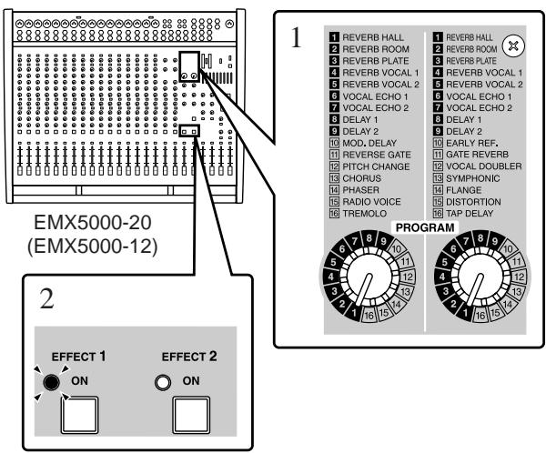
1 Use the PROGRAM selector to select the type of effect that you want to apply.
2 Turn on the ON switch in the EFFECT section. The ON switch indicator lights up.
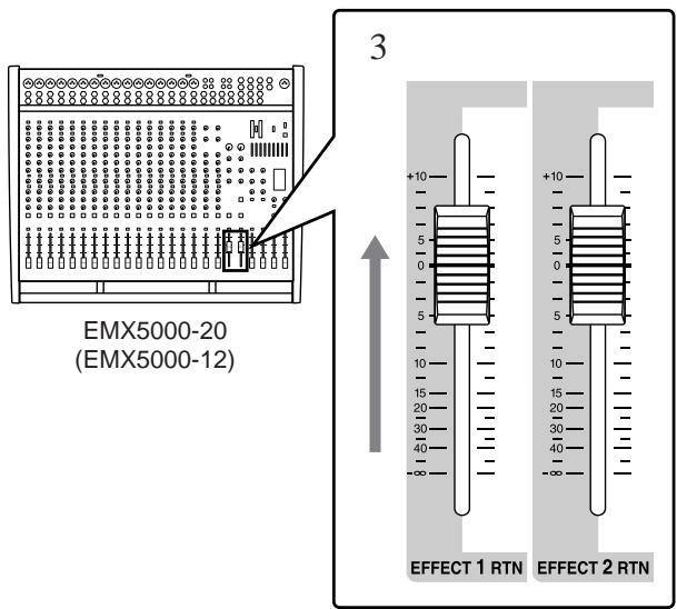
3 Set the EFFECT RTN fader to the "0" position.
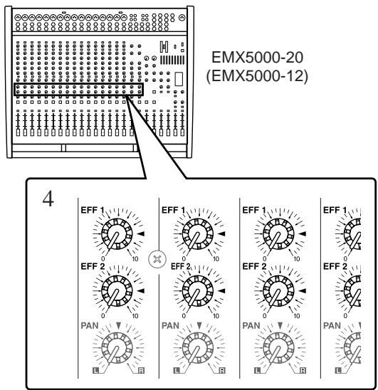
4 If you want to use effect channel 1, adjust the effect depth by turning the EFF1 control of the channel to which you want to apply the effect.
STEP5 Power off
1 Press the POWER switch of the EMX5000-20/ EMX5000-12 to turn off the power to the unit.
2 Turn off the power to all connected devices.
- Be sure to follow the power off sequence specified above to prevent the speakers from being damaged.
- In preparation for the next time you will use the EMX5000-20/EMX5000-12, we recommend that you set the faders of the EMX5000-20/EMX5000-12 to the “ - ” position.
Front and rear panel
Control panel
■ Channel control section
In this section, you can adjust equalization (frequency response), volume level, effect and AUX output levels for the input signal of each channel.
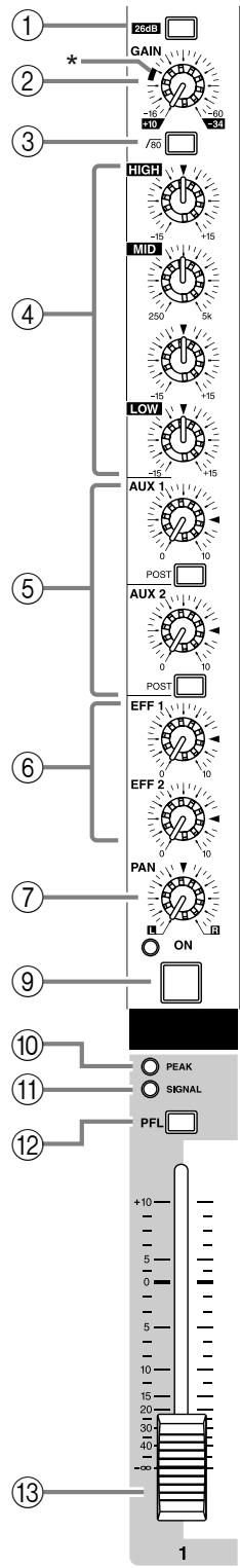
① 26 dB pad switch
This switch attenuates the input signal by 26 dB. Attenuation is on when the switch is pressed inward.
② GAIN control
Use this knob to adjust the sensitivity according to the input signal level, so that the input level is appropriate.
For the best balance of S/N ratio and dynamic range, adjust this knob so that the peak indicator ⑩ lights occasionally.
- When the knob is at the “/” position, the input sensitivity will be +4 dB.
(3) 80 (High pass filter) switch
This is an on/off switch for the high-pass filter. The high-pass filter is on when the switch is pressed inward, and the frequency region below 80Hz will be attenuated at 18 dB/octave.
④ Equalizer controls (HIGH, MID, LOW)
This is a 3-band equalizer that adjusts the high frequency range, mid frequency range, and low frequency range of each channel.
When the HIGH and LOW knobs are in the “▼” position, the high and low ranges will have a flat response. Turning a knob toward the right will boost the corresponding frequency range, and turning it toward the left will cut it.
For the mid range, use the upper MID knob to specify the center frequency of the range, and use the lower knob to set the amount of boost or cut that will occur. The frequency response is flat when the lower knob is set to the “▼” position. Turning the lower knob toward the right will boost the corresponding frequency range, and turning the knob toward the left will cut it.
The base frequency (or center frequency), range of boost or cut, and equalizer type of each band are as follows:
HIGH: 10kHz, ± 15dB , shelving type
MID: 250Hz - 5kHz, ± 15dB , peaking type
LOW: 100Hz, ± 15dB , shelving type
⑤ AUX1, AUX2 controls / POST switches
These knobs adjust the level at which the input signal will be sent to the AUX1 and 2 buses. Nominal level is when the knob is set to the “ ” position. The position from which the signal is sent can be set by the POST switch to either prefader (before the channel fader ⑬ ) or post-fader (after the channel fader ⑬ ). When the switch is pressed inward, post-fader is selected.
The signal will be output from the AUX1 and 2 buses to the AUX SEND 1 and 2 jacks of the input/output section, and can be sent to external monitor amps or powered speakers.
⑥ EFF 1, 2 controls (EFFECT)
For each channel, these control the amount of signal that is sent to the EFFECT 1, 2 buses.
The signal of the EFFECT 1, 2 buses is sent to the EFFECT SEND 1, 2 jack (input/output panel ⑨ ). It is also sent to the built-in effect when the ON switch ⑨ in the digital effect section is turned on.
Note: The amount of signal that is sent to the EFFECT 1, 2 bus from each channel will be affected not only by the setting of the EFFECT 1, 2 control, but also by the setting of the channel fader (post-fader send).
⑦ PAN (panpot) control
(EMX5000-20: Channels 1-16, EMX5000-12: Channels 1-8)
The PAN knobs set the stereo position of the signal that is sent to the STEREO bus. The signal is located in the center when the knob is positioned at “ ,” at right at R, and at left at L.
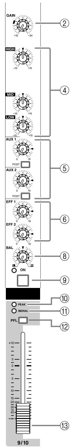
⑧ BAL (balance) control
(EMX5000-20: Channels 17/18-19/20, EMX5000-12: Channels 9/10-11/12)
The BAL knobs set the balance between the left and right channels, and assign the signals received at inputs 17/18-19/20, 9/10-11/12 to the STEREO bus.
ON switch, indicator
This is an on/off switch for the input signal of each channel. The indicator will light if this switch is turned on.
PEAK indicator
The indicator will light 3 dB before clipping, warning that clipping level is near.
⑪ SIGNAL indicator
This indicator will light if a signal is being input to the corresponding channel.
PFL (pre-fader listen) switch
Channels for which this switch is on will send a signal from a post-EQ pre-fader location to the PHONES jack (input/output panel 14). Use this when you wish to use the headphones to monitor only a specific channel.
Note: If this switch is turned on, you can monitor a channel even if the channel fader is lowered, or if the ON switch is off. This will not affect the signals that are sent to the STEREO bus, AUX 1 and 2 buses, and EFFECT bus.
③ Channel fader
This controls the output level of the input channel signal.
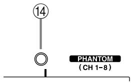
(4) PHANTOM indicator
This will light when the PHANTOM switch (input/output panel ③) is on.
Stereo sub input section
In this section, you can adjust the input level of external equipment connected to the ST SUB IN 1, 2 jacks on the input/output panel.
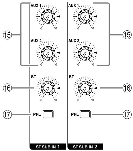
AUX 1, 2 controls
This knob adjusts the amount of the signal sent from the ST SUB IN 1 and 2 jacks (input/output panel ⑦ ) to the AUX 1, 2 buses.
⑥ ST (stereo) control
The ST knob adjusts the amount of stereo signal sent from the ST SUB IN 1 and 2 jacks to the STEREO bus.
PFL (pre-fader listen) switch
When this switch is turned on, the signal at the point before the ST control knob 16 is sent to the PHONES jack (input/output panel 14).
Note: The ST control setting does not affect the level of the signal sent to the PFL/AFL buses (pre-fader send).
Master control section
In this section, you can adjust the final level of the outputs.
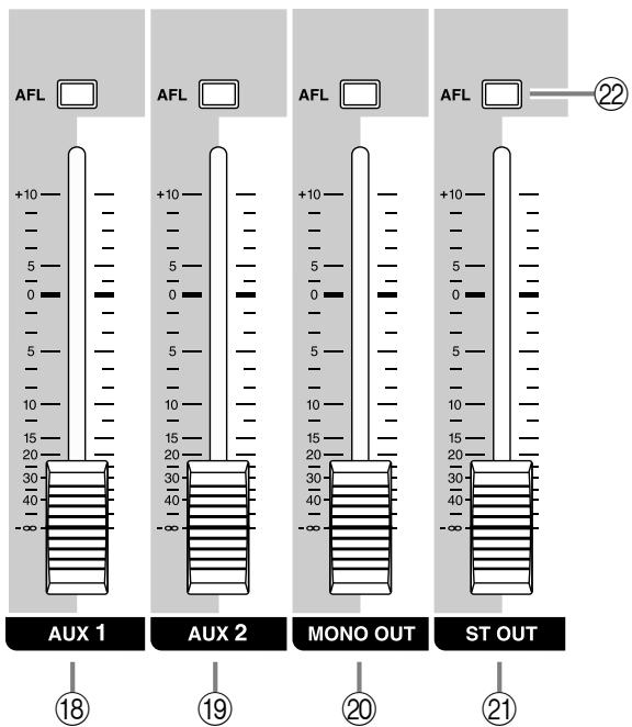
18 AUX 1 fader
The AUX 1 fader adjusts the final level of the signal sent from the AUX 1 bus to the AUX SEND 1 jack (input/output panel ⑧ ). If the Power amp select switch ⑤ is set to AUX 1-MONO, using this fader enables you to adjust the level of the signal sent from the SPEAKERS A 1/2 jacks to the speakers.
19 AUX 2 fader
The AUX 2 fader adjusts the final level of the signal output from the AUX 2 bus to the AUX SEND 2 jack (input/output panel ⑧ ). If the Power amp select switch ⑤ is set to AUX 1-AUX 2, using this fader enables you to adjust the level of the signal sent from the SPEAKERS B 1/2 jacks to the speakers.
20 MONO OUT fader
The MONO OUT fader adjusts the final level of the monaural signal output from the STEREO bus to the MONO OUT jack (input/output panel ⑬).
If the Power amp select switch ⑤ is set to AUX 1-MONO, this fader also adjusts the level of the signal sent from the SPEAKERS B 1/2 jacks to the speakers.
If the Power amp select switch ③5 is set to MONO BRIDGE, this fader adjusts the level of the signal sent from the SPEAKERS A 1 jacks to the speaker.
② ST OUT fader
The ST OUT fader adjusts the final level of the signal sent from the STEREO bus to the ST OUT jacks (input/output panel ⑩). If the Power amp select switch ③5 is set to ST L-R, this fader also adjusts the level of the signal sent to the SPEAKERS jacks (rear panel ③).
Note: The setting of this fader does not affect the signal output from the STEREO bus to the ST SUB OUT jacks.
AFL (after fader listen) switch
When this switch is on, the output signal that passes through the corresponding fader is sent to the PHONES jack (input/output panel 14). Use these switches when you wish to monitor a particular output signal through the headphones.
2TR IN section
In this section, you can adjust the input level of a cassette deck or a CD player that is connected to the 2TR IN jacks (input/output panel ⑤).
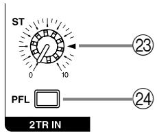
23 ST (stereo) control
This knob adjusts the level of the signal sent from the 2TR IN jacks to the STEREO bus.
24 PFL (pre-fader listen) switch
When this switch is on, the signal input from the 2TR IN jacks is routed at the point before the ST control ② to the PHONES jack (input/output panel ④ ).
Digital effect section
This section enables you to turn the built-in two-channel digital effects on/off and select the effect type.
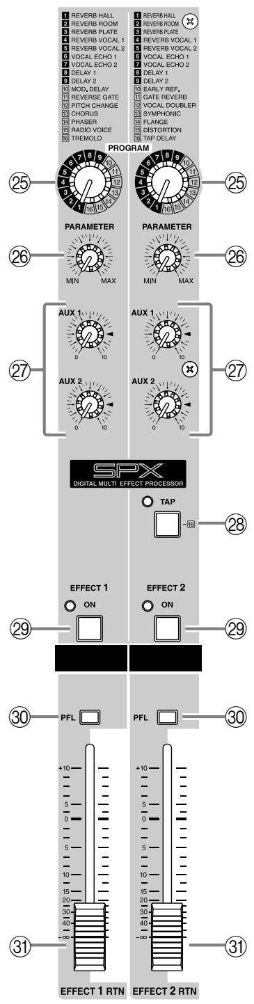
25 PROGRAM selector
This knob selects the effect type for the internal digital effect.
26 PARAMETER control
This knob adjusts the time parameter of the internal digital effect.
⑦ AUX 1/2 control
This knob adjusts the level of the return signal that is sent from the built-in digital effect to the AUX 1/2 buses.
TAP switch, indicator
Only if the PROGRAM selector has selected TAP DELAY as the internal effect type, you can press this switch to set the desired delay time.
Press the TAP switch several times, and the interval between the last two presses will be set as the delay time. The specified time will be remembered even if the power is turned off.
The LED beside the switch will blink in synchronization with the delay time only when the effect type is TAP DELAY.
29 EFFECT 1/2 ON switch
This switch turns the internal digital effect on/off.
PFL (Pre-fader listen) switch
When this switch is on, the signal from before the EFFECT 1/2 RTN faders ③ will be sent to the PHONES jack (input/output panel ④ ).
③ EFFECT 1/2 RTN fader
This fader adjusts the level of the return signal that is sent from the built-in digital effect to the STEREO bus.
■ Graphic equalizer section
This section enables you to adjust the tone of the STEREO bus signal.
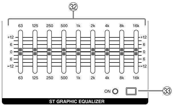
② Graphic equalizer
This is a 9-band graphic equalizer that allows you to adjust the frequency response of the STEREO bus signal, providing a maximum of ± 12 dB of cut/boost for each frequency band.
This graphic equalizer affects both the STEREO bus signal that is output to the speakers and the line level signal that is output from the ST OUT jacks (input/output panel 10), and MONO OUT jack (input/output panel 13).
③ ON switch
This switch turns the graphic equalizer on/off.
Power amp section
This section allows you to select the signals that will be sent to the built-in two-channel power amplifier.
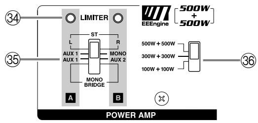
(34) LIMITER indicator
This indicator lights up when the level of the signal output from the power amp section reaches the maximum and the limiter is activated. Adjust the ST OUT 21 and appropriate fader so that the indicator lights up for only a short while when the signal reaches the maximum level.
Note: The indicator lights up or flashes for a longer duration if the power amp section is significantly overloaded, which could result in malfunction. Avoid such a situation.
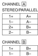
⑤ Power amp select switch
Select one of the following three settings to specify the signals to be routed to the corresponding jacks according to the speaker connection at the SPEAKERS jacks ③ on the rear panel.
ST L-R
The STEREO bus signals are output from the SPEAKERS A 1/2 jacks and the SPEAKERS B 1/2 jacks. The final level of these signals is adjusted by the master ST OUT fader.
AUX 1-MONO
The AUX 1 bus signals are output from the SPEAKERS A 1/2 jacks, and a monaural signal that is a mix of the STEREO bus signals is output from the SPEAKERS B 1/2 jacks. The final level of these signals is adjusted by the master AUX 1 fader and the MONO OUT fader.
AUX 1-AUX 2
The AUX 1, 2 buses signals are output from the SPEAKERS A 1/2 jacks and the SPEAKERS B 1/2 jacks.
- MONO BRIDGE
The monaural signal that is a mix of the STEREO bus is output from the SPEAKERS A 1 jack. The final level of this signal is adjusted by the master MONO OUT fader.
Set the switch to this position when you connect only one speaker to play a loud sound.
Maximum output select switch
This switch lets you change the maximum output level of the two internal power amps between three levels.
Set this as appropriate for the size of the room or the input capacity of the speakers.
- 500W + 500W
The two internal amps will produce a maximum of 500W + 500W / 4
- 300W + 300W
The two internal amps will produce a maximum of 300W + 300W / 4
- 100W + 100W
The two internal amps will produce a maximum of 100W + 100W / 4
■ POWER indicator
③ POWER indicator
This indicator will light up when the power of the EMX5000-20/EMX5000-12 is turned on.

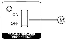
YAMAHA SPEAKER PROCESSING
③ ON/OFF switch
This switch enables you to compensate the low range of the speakers. The low range balance when this switch is on varies depending on the speakers.
First, check the low range balance by auditioning the resultant sound, then set this switch to on or off.
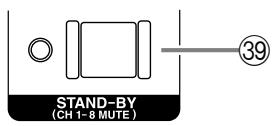
STAND-BY
39 ON/OFF switch
This switch mutes (silences) the input signals from channels 1-16 (EMX5000-20) or channels 1-8 (EMX5000-12). The indicator will blink when this switch is on.
Other indicators and controls
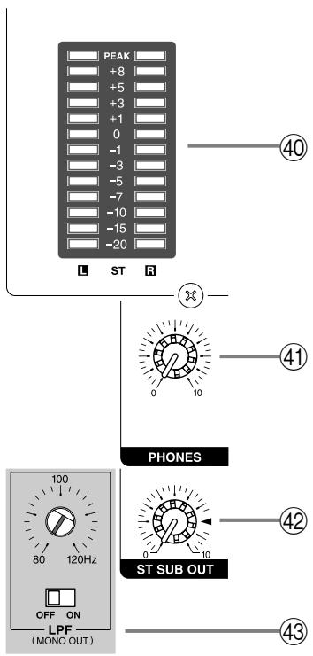
40 Peak level indicator
This indicator allows you to monitor the level of the signal output from the ST OUT jacks. The "0" indicator lights up when the output level reaches +4 dB.
④ PHONES control
This knob adjusts the level of the signal monitored via the PHONES jack (input/output panel 14).
42 ST SUB OUT control
This knob adjusts the final level of the signal sent from the STEREO bus to the ST SUB OUT jacks (input/output panel ⑪).
Note: The setting of this control does not affect signals that are sent from the STEREO bus to the ST SUB OUT jacks and the SPEAKERS jacks.
43 LPF control, ON/OFF switch
This switch applies a low-pass filter to the signal that is output from the PFL/AFL bus to the MONO OUT jack. The frequency is indicated by the position of the slit in the control trimmer that is set into the panel above the switch. To adjust the frequency, use a slotted screwdriver to turn the control to the desired position. This will output the region below the frequency (80-120 Hz) you specify by the control knob.
Use this when you are using a sub-woofer.
Input/output panel
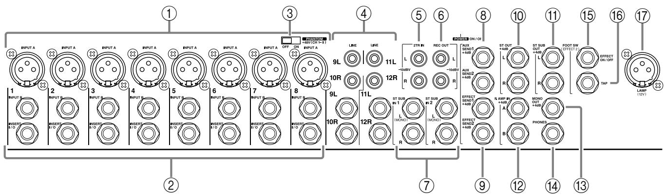
① Channel input jacks (INPUT A, INPUT B) EMX5000-20: 1-16, EMX5000-12: 1-8
By using the GAIN control (control panel 2) you can connect any of the jacks to a wide range of sources, from mics to line-level devices (including synthesizers and rhythm machines). The INPUT A jacks can provide +48V phantom power, allowing you to use condenser microphones.
The nominal input level is from -16dB to -60dB when the 26 dB pad switch (control panel ①) is off, or from +10dB to -34dB when it is on.
Both INPUT A and B are balanced.
They are compatible with microphones of output impedance 50 - 600 or line level devices of 600 .
Pin connections for the jacks are as follows:
| INPUT A jacks (XLR type) | INPUT B jacks (TRS phone jacks) * |
| Pin 1: ground | Sleeve: ground |
| Pin 2: hot (+) | Tip: hot (+) |
| Pin 3: cold (-) | RIng: cold (-) |
- You can also connect a normal unbalanced phone plug.
Note: It is not possible to simultaneously use both the INPUT A and B inputs of a given channel. For each channel, use only one of the inputs as appropriate for the input source. Phantom power is switched on/off simultaneously for channels 1-8 and 9-16 (EMX5000-20), 1-8 (EMX5000-12). For this reason, devices (in particular, unbalanced devices) other than condenser microphones must be connected to the INPUT B input jacks of channels or channel 17/18-19/20 (EMX5000-20), 9/10-11/12 (EMX5000-12) input jacks if the PHANTOM +48V switch (control panel ③) is on.
② INSERT I/O (insert) jacks
These are TRS phone jacks that enable you to insert an external effect processor, such as a compressor/limiter, between the equalizer and fader of input channels. These connections require a special "Y" cable, such as shown in the following diagram. The nominal input/output levels are 0 dB.
(3) PHANTOM switch
This is an on/off switch for the phantom power supplied to the INPUT A jacks of channels 1-8 and 9-16 (on the EMX5000-20) or channels 1-8 (on the EMX5000-12). When this switch is on, the indicator in the upper part of the control panel will light.
LINE (stereo) input jacks EMX5000-20: 17/18-19/20, EMX5000-12: 9/10-11/12
These are the input jacks for channels 17/18-19/20, 9/10-11/12 and are used to connect to the stereo output jacks of electronic instruments, cassette decks, or CD players.
You can connect either phone plugs or RCA phono plugs, as appropriate for the type of jack on the device you are connecting. The nominal input level is from -34dB to +10dB .
⑤ 2TR IN jacks
These are phono jacks that allow the signal from an external device, such as a cassette deck and CD player, to be added to the STEREO bus. The nominal input level is -10dBV .
⑥ REC OUT jacks
These phono jacks are used to connect to the inputs of a recording device, such as a cassette deck, to record the signal from the STEREO bus. The nominal output level is -10 dBV.
Note: The setting of the graphic equalizer or ST OUT fader on the control panel does not affect the signals output from these jacks. Adjust the recording level on the recording device.
⑦ ST SUB IN 1 (stereo sub 1) jacks
ST SUB IN 2 (stereo sub 2) jacks
These phone jacks are used to connect stereo outputs of a sub mixer or external effect processor. The signal input here can be routed to the AUX 1 bus, AUX 2 bus, and STEREO bus. The nominal input level is +4 dB.
Note: Use only the L jack to connect a monaural output device.
AUX SEND 1 jack, AUX SEND 2 jack
These phone jacks output the line-level signals of the AUX 1/2 buses. Connect stage-monitoring amplifiers or powered speakers here. Use the AUX 1 fader (control panel 18) and the AUX 2 fader (control panel 19) respectively to adjust the final level of the signals output from these jacks. The nominal output level is +4 dB.
(9) EFFECT SEND 1 jack, EFFECT SEND 2 jack The input of an external effect unit such as a delay or echo can be connected to this jack.
The signal adjusted by the EFF 1, 2 control of each channel will be sent to the EFFECT 1, 2 bus, and output from this jack.
The nominal output level is +4 dB.
⑩ ST OUT jacks
These phone jacks output the line level signal of the STEREO bus. The final output level from these jacks is adjusted by the ST OUT fader (control panel ②). The nominal output level is +4 dB.
⑪ ST SUB OUT jacks
These phone jacks output the line-level signals of the STEREO bus. Connect an external mixer or additional PA system to these jacks.
Use the ST SUB OUT control (control panel 42) to adjust the final output level at the ST SUB OUT jacks.
The nominal output level is +4 dB.
P.AMP IN A, B (power amp input) jacks
These phone jacks are used to input line-level stereo signals to the two-channel built-in power amplifier. Connect an external mixer output here. The nominal input level is +4 dB.
Note: If you insert a plug into this jack, the corresponding channel of the power amplifier will be isolated, and no signals will be sent from the mixer section.
③ MONO OUT jack
This phone jack mixes the STEREO bus signals and output a monaural signal. Connect an additional PA system here. Use the MONO OUT fader (control panel ② ) to adjust the final level of the signal output from this jack. The nominal output level is +4 dB.
⑭ PHONES jack
This is a stereo phone type output jack, and is used to monitor the channels selected by the PFL switches on the front panel and the buses selected by the AFL switches.
The nominal output is 3mW when headphones are connected.
(15) FOOT SW EFFECT 2 ON/OFF jack
A separately sold Yamaha FC5 foot switch can be connected to this jack so you can use your foot to switch the built-in digital EFFECT 2 on/off.