RT0700C - Router MAKITA - Free user manual and instructions
Find the device manual for free RT0700C MAKITA in PDF.
| Product type | Router (trimmer) |
| Brand | MAKITA |
| Model | RT0700C |
| Collet capacity | 6 mm, 8 mm, 1/4", 3/8" |
| No-load speed | 10,000 – 30,000 rpm |
| Speed adjustment | 6-position dial (1 to 6) |
| Electronic functions | Constant speed control, soft start |
| Overall length | 200 mm |
| Net weight | 1.8 kg (according to EPTA 01/2003) |
| Power supply | Single-phase mains, double insulation (without earthing) |
| Applications | Trimming and profiling of wood, plastic and similar materials |
| Sound pressure level (LpA) | 82 dB(A) (uncertainty K=3 dB(A)) |
| Sound power level (LWA) | 93 dB(A) (uncertainty K=3 dB(A)) |
| Vibration (no-load rotation) | ≤ 2.5 m/s² (uncertainty K=1.5 m/s²) |
| Vibration (grooving in MDF) | 3.5 m/s² (uncertainty K=1.5 m/s²) |
| Depth adjustment | By adjusting screw and locking lever; plunge with optional base |
| Parallel guide | Optional accessory for straight cuts |
| Template guide | Optional accessory for template copying |
| Plunge base | Optional accessory for use as a router |
| Offset base | Optional accessory for work in corners |
| Dust extraction adapter | Optional accessory for dust extraction |
| Maintenance | Brush replacement (check regularly) |
| Safety | Double insulation; on/off switch; wear ear protectors |
| Standards | Compliant with EN60745; Directive 2006/42/EC |
Frequently Asked Questions - RT0700C MAKITA
User questions about RT0700C MAKITA
0 question about this device. Answer the ones you know or ask your own.
Ask a new question about this device
Download the instructions for your Router in PDF format for free! Find your manual RT0700C - MAKITA and take your electronic device back in hand. On this page are published all the documents necessary for the use of your device. RT0700C by MAKITA.
USER MANUAL RT0700C MAKITA
Explanation of general view
| 1 | Bit protrusion | 29 | Bolt | 55 | Grip attachment (optional accessory) |
| 2 | Tool base | 30 | Guide plate | ||
| 3 | Scale | 31 | Wing nut | 56 | Trimmer base |
| 4 | Locking lever | 32 | Clamp screw (A) | 57 | Knob type grip |
| 5 | Adjusting screw | 33 | Center hole | 58 | Plunge base |
| 6 | Hex nut | 34 | Nail | 59 | Grip |
| 7 | Switch | 35 | Clamp screw (A) | 60 | Knob |
| 8 | OFF (O) side | 36 | Adjusting screw | 61 | Adjusting knob |
| 9 | ON (I) side | 37 | Clamp screw (B) | 62 | Lock lever |
| 10 | Speed adjusting dial | 38 | Trimmer guide | 63 | Depth pointer |
| 11 | Tighten | 39 | Bit | 64 | Stopper pole setting nut |
| 12 | Loosen | 40 | Guide roller | 65 | Fast-feed button |
| 13 | Hold | 41 | Clamping screws | 66 | Stopper pole |
| 14 | Shaft lock | 42 | Base protector | 67 | Stopper block |
| 15 | Workpiece | 43 | Screw | 68 | Adjusting bolt |
| 16 | Bit revolving direction | 44 | Pulley | 69 | Guide holder |
| 17 | View from the top of the tool | 45 | Collet nut | 70 | Wing bolts |
| 18 | Feed direction | 46 | Collet cone | 71 | Guide bar |
| 19 | Straight guide | 47 | Wrench | 72 | Wing bolt |
| 20 | Base protector | 48 | Belt | 73 | Outside diameter of the templet guide |
| 21 | Screws | 49 | Locking lever | ||
| 22 | Screwdriver | 50 | Offset base | 74 | Templet guide |
| 23 | Straight bit | 51 | Hex wrench | 75 | Dust nozzle |
| 24 | Base | 52 | Offset base plate | 76 | Thumb screw |
| 25 | Templet | 53 | Upper section of the offset base | 77 | Limit mark |
| 26 | Distance (X) | 54 | Bar type grip (optional accessory) | 78 | Brush holder cap |
| 27 | Templet guide 10 | ||||
| 28 | Base protector |
SPECIFICATIONS
GEA010-1
| Model | RT0700C |
| Collet chuck capacity | .6 mm, 8 mm, 1/4" or 3/8" |
| No load speed (min-1) | 10,000 – 30,000 |
| Overall length | 200 mm |
| Net weight | 1.8 kg |
| Safety class | ☐ /II |
- Due to the continuing program of research and development, the specifications herein are subject to change without prior notice.
- Specifications may differ from country to country.
Weight according to EPTA-Procedure 01/2003
ENE010-1
Intended use
The tool is intended for flush trimming and profiling of wood, plastic and similar materials.
ENF002-1
Power supply
The tool should be connected only to a power supply of the same voltage as indicated on the nameplate, and can only be operated on single-phase AC supply. They are double-insulated in accordance with European Standard and can, therefore, also be used from sockets without earth wire.
General Power Tool SafetyWarnings
WARNING Read all safety warnings and all instructions. Failure to follow the warnings and instructions may result in electric shock, fire and/or serious injury.
Save all warnings and instructions for future reference.
GEB019-4
TRIMMER SAFETY WARNINGS
- Hold power tool by insulated gripping surfaces, because the cutter may contact its own cord. Cutting a "live" wire may make exposed metal parts of the power tool "live" and shock the operator.
- Use clamps or another practical way to secure and support the workpiece to a stable platform. Holding the work by hand or against your body leaves it unstable and may lead to loss of control.
- Wear hearing protection during extended period of operation.
- Handle the bits very carefully.
- Check the bit carefully for cracks or damage before operation. Replace cracked or damaged bit immediately.
- Avoid cutting nails. Inspect for and remove all nails from the workpiece before operation.
- Hold the tool firmly.
- Keep hands away from rotating parts.
-
Make sure the bit is not contacting the workpiece before the switch is turned on.
-
Before using the tool on an actual workpiece, let it run for a while. Watch for vibration or wobbling that could indicate improperly installed bit.
- Be careful of the bit rotating direction and the feed direction.
- Do not leave the tool running. Operate the tool only when hand-held.
- Always switch off and wait for the bit to come to a complete stop before removing the tool from workpiece.
- Do not touch the bit immediately after operation; it may be extremely hot and could burn your skin.
- Do not smear the tool base carelessly with thinner, gasoline, oil or the like. They may cause cracks in the tool base.
- Use bits of the correct shank diameter suitable for the speed of the tool.
- Some material contains chemicals which may be toxic. Take caution to prevent dust inhalation and skin contact. Follow material supplier safety data.
- Always use the correct dust mask/respirator for the material and application you are working with.
SAVE THESE INSTRUCTIONS.
WARNING:
DO NOT let comfort or familiarity with product (gained from repeated use) replace strict adherence to safety rules for the subject product. MISUSE or failure to follow the safety rules stated in this instruction manual may cause serious personal injury.
FUNCTIONAL DESCRIPTION
CAUTION:
Always be sure that the tool is switched off and unplugged before adjusting or checking function on the tool.
Adjusting bit protrusion (Fig. 1)
To adjust the bit protrusion, loosen the locking lever and move the tool base up or down as desired by turning the adjusting screw. After adjusting, tighten the locking lever firmly to secure the tool base.
NOTE:
- When the tool is not secured even if the locking lever is tightened, tighten the hex nut and then tighten the locking lever.
Switch action (Fig. 2)
CAUTION:
- Before plugging in the tool, always check to see that the tool is switched off.
To start the tool, press the "ON (I)" side of the switch. To stop the tool, press the "OFF (O)" side of the switch.
Electronic function
The tool equipped with electronic function are easy to operate because of the following features.
Constant speed control
Electronic speed control for obtaining constant speed. Possible to get fine finish, because the rotating speed is kept constant even under load condition.
Soft start
Soft-start feature minimizes start-up shock, and makes the tool start smoothly.
Speed adjusting dial (Fig. 3)
The tool speed can be changed by turning the speed adjusting dial to a given number setting from 1 to 6.
Higher speed is obtained when the dial is turned in the direction of number 6. And lower speed is obtained when it is turned in the direction of number 1.
This allows the ideal speed to be selected for optimum material processing, i.e. the speed can be correctly adjusted to suit the material and bit diameter.
Refer to the table for the relationship between the number settings on the dial and the approximate tool speed.
| Number | \( \mathbf{{mi}{n}^{-1}} \) |
| 1 | 10,000 |
| 2 | 12,000 |
| 3 | 17,000 |
| 4 | 22,000 |
| 5 | 27,000 |
| 6 | 30,000 |
CAUTION:
- If the tool is operated continuously at low speeds for a long time, the motor will get overloaded, resulting in tool malfunction.
- The speed adjusting dial can be turned only as far as 6 and back to 1. Do not force it past 6 or 1, or the speed adjusting function may no longer work.
ASSEMBLY
CAUTION:
- Always be sure that the tool is switched off and unplugged before carrying out any work on the tool.
Installing or removing trimmer bit (Fig. 4 & 5)
CAUTION:
- Do not tighten the collet nut without inserting a bit, or the collet cone will break.
- Use only the wrenches provided with the tool.
Insert the bit all the way into the collet cone and tighten the collet nut securely with the two wrenches or by pressing the shaft lock and using the provided wrench.
To remove the bit, follow the installation procedure in reverse.
OPERATION
For the trimmer base (Fig. 6)
WARNING:
- Before using the tool with the trimmer base, always install the dust nozzle on the trimmer base.
Set the tool base on the workpiece to be cut without the bit making any contact. Then turn the tool on and wait until the bit attains full speed. Move the tool forward over the workpiece surface, keeping the tool base flush and advancing smoothly until the cutting is complete. When doing edge cutting, the workpiece surface should be on the left side of the bit in the feed direction. (Fig. 7)
NOTE:
- Moving the tool forward too fast may cause a poor quality of cut, or damage to the bit or motor. Moving the tool forward too slowly may burn and mar the cut. The proper feed rate will depend on the bit size, the kind of workpiece and depth of cut. Before beginning the cut on the actual workpiece, it is advisable to make a sample cut on a piece of scrap lumber. This will show exactly how the cut will look as well as enable you to check dimensions.
- When using the trimmer shoe, the straight guide or the trimmer guide, be sure to keep it on the right side in the feed direction. This will help to keep it flush with the side of the workpiece. (Fig. 8)
CAUTION:
- Since excessive cutting may cause overload of the motor or difficulty in controlling the tool, the depth of cut should not be more than 3mm at a pass when cutting grooves. When you wish to cut grooves more than 3mm deep, make several passes with progressively deeper bit settings.
Templet guide
The templet guide provides a sleeve through which the bit passes, allowing use of the trimmer with templet patterns. (Fig. 9)
Loosen the screws and remove the base protector. Place the templet guide on the base and replace the base protector. Then secure the base protector by tightening the screws. (Fig. 10)
Secure the templet to the workpiece. Place the tool on the templet and move the tool with the templet guide sliding along the side of the templet. (Fig. 11)
NOTE:
- The workpiece will be cut a slightly different size from the templet. Allow for the distance (X) between the router bit and the outside of the templet guide. The distance (X) can be calculated by using the following equation:
Distance (X) = (outside diameter of the templet guide - router bit diameter) / 2
Straight guide (Accessory)
The straight guide is effectively used for straight cuts when chamfering or grooving. (Fig. 12)
Attach the guide plate to the straight guide with the bolt and the wing nut. (Fig. 13)
Attach the straight guide with the clamp screw (A). Loosen the wing nut on the straight guide and adjust the distance between the bit and the straight guide. At the desired distance, tighten the wing nut securely.
When cutting, move the tool with the straight guide flush with the side of the workpiece. (Fig. 14)
If the distance (A) between the side of the workpiece and the cutting position is too wide for the straight guide, or if the side of the workpiece is not straight, the straight guide cannot be used. In this case, firmly clamp a straight board to the workpiece and use it as a guide against the trimmer base. Feed the tool in the direction of the arrow. (Fig. 15)
Circular work
Circular work may be accomplished if you assemble the straight guide and guide plate as shown in Fig. 16 or 17. Min. and max. radius of circles to be cut (distance between the centre of circle and the centre of bit) are as follows:
Min.: 70 mm
Max.: 221 mm
Fig. 16 for cutting circles between 70~mm and 121~mm in radius.
Fig. 17 for cutting circles between 121mm and 221mm in radius.
NOTE:
- Circles between 172mm and 186mm in radius cannot be cut using this guide.
Align the centre hole in the straight guide with the centre of the circle to be cut. Drive a nail less than 6mm in diameter into the centre hole to secure the straight guide. Pivot the tool around the nail in clockwise direction. (Fig. 18)
Trimmer guide (optional accessory)
Trimming, curved cuts in veneers for furniture and the like can be done easily with the trimmer guide. The guide roller rides the curve and assures a fine cut. (Fig. 19)
Install the trimmer guide on the tool base with the clamp screw (A). Loosen the clamp screw (B) and adjust the distance between the bit and the trimmer guide by turning the adjusting screw (1 mm per turn). At the desired distance, tighten the clamp screw (B) to secure the trimmer guide in place. (Fig. 20)
When cutting, move the tool with the guide roller riding the side of the workpiece. (Fig. 21)
Tilt base (optional accessory)
Tilt base (optional accessory) is convenient for chamfer-ing. (Fig. 22)
Place the tool onto the tilt base and close the locking lever at the desired protrusion of the bit. For desired angle, tighten the clamping screws on its sides.
Firmly clamp a straight board to the workpiece and use it as a guide against the trimmer base. Feed the tool in the direction of the arrow.
Base protector removed from the tilt base (optional accessory)
Mounting the base protector which has been removed from the tilt base on the trimmer base allows the change of the trimmer base from the round base to a square base.
For another application, remove the base protector from the tilt base by loosening and removing four screws. (Fig. 23)
And then mount the base protector on the trimmer base.
Offset base (optional accessory)
(1) Offset base (optional accessory) is convenient for work in a tight area such as a corner. (Fig. 24 & 25)
Before installing the tool on the offset base, remove the collet nut and collet cone by loosening the collet nut. (Fig. 26)
Install the pulley on the tool by pressing the shaft lock and firmly tightening the pulley with a wrench. (Fig. 27)
Place the collet cone and screw the collet nut on the offset base as shown in the figure. (Fig. 28)
Mount the tool on the offset base. (Fig. 29)
Put an end of the belt over the pulley using a screwdriver and make sure that its entire belt width fits over the pulley completely. (Fig. 30)
Secure it with a locking lever on the offset base. (Fig. 31)
To install the bit, fall the tool with the offset base on its side. Insert the hex wrench into the hole in the offset base.
With the hex wrench held in that position, insert the bit into the collet cone on the shaft of the offset base from the opposite side and tighten the collet nut firmly with a wrench.
To remove the bit at replacement, follow the installation procedure in reverse.
(2) Offset base (optional accessory) can also be used with a trimmer base and a grip attachment (optional accessory) for more stability. (Fig. 32)
Loosen the screws and remove the upper section from the offset base. Put aside the upper section of the offset base. (Fig. 33)
Mount the trimmer base with four screws and the grip attachment (optional accessory) with two screws on the offset base plate.
Screw a bar type grip (optional accessory) onto the grip attachment. (Fig. 34)
In another way of use, the knob type grip which is removed from a plunge base (optional accessory) can be installed on the grip attachment. To install the knob type grip, place it on the grip attachment and secure it with a screw. (Fig. 35)
When using as a router only with a plunge base (optional accessory)
CAUTION:
- When using as a router, hold the tool firmly with both hands.
To use the tool as a router, install the tool on a plunge base (optional accessory) by pressing it down fully. (Fig. 36)
Either knob type grip or bar type grip (optional accessory) can be used according to your work. (Fig. 37)
To use the bar type grip (optional accessory), loosen the screw and remove the knob type grip. (Fig. 38)
And then screw the bar type grip on the base.
Adjusting the depth of cut when using the plunge base (optional accessory)
Place the tool on a flat surface. Loosen the lock lever and lower the tool body until the bit just touches the flat surface. Tighten the lock lever to lock the tool body. (Fig. 39)
Turn the stopper pole setting nut counterclockwise.
Lower the stopper pole until it makes contact with the adjusting bolt. Align the depth pointer with the "0" graduation. The depth of cut is indicated on the scale by the depth pointer.
While pressing the fast-feed button, raise the stopper pole until the desired depth of cut is obtained. Minute depth adjustments can be obtained by turning the adjusting knob (1 mm per turn).
By turning the stopper pole setting nut clockwise, you can fasten the stopper pole firmly.
Now, your predetermined depth of cut can be obtained by loosening the lock lever and then lowering the tool body until the stopper pole makes contact with the adjusting hex bolt of the stopper block.
Always firmly hold the tool by both grip during operation.
Set the tool base on the workpiece to be cut without the bit making any contact. Then turn the tool on and wait until the bit attains full speed. Lower the tool body and move the tool forward over the workpiece surface, keeping the tool base flush and advancing smoothly until the cutting is complete.
When doing edge cutting, the workpiece surface should be on the left side of the bit in the feed direction. (Fig. 40)
NOTE:
-
Moving the tool forward too fast may cause a poor quality of cut, or damage to the bit or motor. Moving the tool forward too slowly may burn and mar the cut. The proper feed rate will depend on the bit size, the kind of workpiece and depth of cut. Before beginning the cut on the actual workpiece, it is advisable to make a sample cut on a piece of scrap lumber. This will show exactly how the cut will look as well as enable you to check dimensions.
-
When using the straight guide, be sure to install it on the right side in the feed direction. This will help to keep it flush with the side of the workpiece. (Fig. 41)
Straight guide when using as a router (needed to use with guide holder (optional accessory))
The straight guide is effectively used for straight cuts when chamfering or grooving. (Fig. 42)
Install the straight guide on the guide holder (optional accessory) with the wing nut.
Insert the guide holder into the holes in the plunge base and tighten the wing bolts. To adjust the distance between the bit and the straight guide, loosen the wing nut. At the desired distance, tighten the wing nut to secure the straight guide in place.
Straight guide (optional accessory)
The straight guide is effectively used for straight cuts when chamfering or grooving. (Fig. 43 & 44)
To install the straight guide, insert the guide bars into the holes in the plunge base. Adjust the distance between the bit and the straight guide. At the desired distance, tighten the wing bolts to secure the straight guide in place.
When cutting, move the tool with the straight guide flush with the side of the workpiece. (Fig. 45)
If the distance (A) between the side of the workpiece and the cutting position is too wide for the straight guide, or if the side of the workpiece is not straight, the straight guide cannot be used. In this case, firmly clamp a straight board to the workpiece and use it as a guide against the router base. Feed the tool in the direction of the arrow.
Templet guide (Accessory)
The templat guide provides a sleeve through which the bit passes, allowing use of the tool with templat patterns.
(Fig. 46)
To install the templet guide, loosen the screws on the tool base, insert the templet guide and then tighten the screws. (Fig. 47)
Secure the templet to the workpiece. Place the tool on the templet and move the tool with the templet guide sliding along the side of the templet. (Fig. 48)
NOTE:
- The workpiece will be cut a slightly different size from the templet. Allow for the distance (X) between the bit and the outside of the templet guide.
The distance (X) can be calculated by using the following equation:
Distance (X) = (outside diameter of the templet guide - bit diameter) / 2
Dust nozzle sets
For the trimmer base (Fig. 6)
For the plunge base (optional accessory) (Fig. 49)
Use the dust nozzle for dust extraction. Install the dust nozzle on the tool base using the thumb screw so that protrusion on the dust nozzle fit to the notch in the tool base.
Then connect a vacuum cleaner to the dust nozzle. (Fig. 50)
MAINTENANCE
CAUTION:
Always be sure that the tool is switched off and unplugged before attempting to perform inspection or maintenance.
- Never use gasoline, benzine, thinner, alcohol or the like. Discoloration, deformation or cracks may result.
Replacing carbon brushes
Remove and check the carbon brushes regularly. Replace when they wear down to the limit mark. Keep the carbon brushes clean and free to slip in the holders. Both carbon brushes should be replaced at the same time. Use only identical carbon brushes. (Fig. 51)
Use a screwdriver to remove the brush holder caps. Take out the worn carbon brushes, insert the new ones and secure the brush holder caps. (Fig. 52)
To maintain product SAFETY and RELIABILITY, repairs, any other maintenance or adjustment should be performed by Makita Authorized Service Centers, always using Makita replacement parts.
OPTIONAL ACCESSORIES
CAUTION:
- These accessories or attachments are recommended for use with your Makita tool specified in this manual. The use of any other accessories or attachments might present a risk of injury to persons. Only use accessory or attachment for its stated purpose.
If you need any assistance for more details regarding these accessories, ask your local Makita Service Center.
- Straight & groove forming bits
- Edge forming bits
- Laminate trimming bits
- Straight guide assembly
- Trimmer guide assembly
- Trimmer base assembly
- Tilt base assembly
- Plunge base assembly
- Offset base assembly
Templet guide
Collet cone 6 mm
Collet cone 6.35 mm (1/4")
Collet cone 8 mm
Collet cone 9.53 mm (3/8")
Wrench 13
Wrench 22
NOTE:
- Some items in the list may be included in the tool package as standard accessories. They may differ from country to country.
ENG905-1
Noise
The typical A-weighted noise level determined according to EN60745:
Sound pressure level (L_DA) .. 82 dB A
Sound power level (L_WA) : 93 dB (A)
Uncertainty (K): 3 dB (A)
Wear ear protection
ENG900-1
Vibration
The vibration total value (tri-axial vector sum) determined according to EN60745:
Work mode: rotation without load
Vibration emission (a_h):2.5m / s^2 or less
Uncertainty (K): 1.5m / s^2
Work mode : cutting grooves in MDF
Vibration emission (a_h):3.5m / s^2
Uncertainty (K): 1.5m / s^2
ENG901-1
- The declared vibration emission value has been measured in accordance with the standard test method and may be used for comparing one tool with another.
- The declared vibration emission value may also be used in a preliminary assessment of exposure.
WARNING:
- The vibration emission during actual use of the power tool can differ from the declared emission value depending on the ways in which the tool is used.
- Be sure to identify safety measures to protect the operator that are based on an estimation of exposure in the actual conditions of use (taking account of all parts of the operating cycle such as the times when the tool is switched off and when it is running idle in addition to the trigger time).
For European countries only
EC Declaration of Conformity
We Makita Corporation as the responsible manufacturer declare that the following Makita machine(s):
Designation of Machine: Trimmer
Model No./ Type: RT0700C
are of series production and
Conforms to the following European Directives:
2006/42/EC
And are manufactured in accordance with the following standards or standardised documents:
EN60745
The technical documentation is kept by our authorized
representative in Europe who is:
Makita International Europe Ltd.
Michigan Drive, Tongwell,
Milton Keynes, MK15 8JD, England
14.10.2010

Tomoyasu Kato
Director
Makita Corporation
3-11-8, Sumiyoshi-cho,
Anjo, Aichi, JAPAN
Descriptif
Michigan Drive, Tongwell,
Milton Keynes, MK15 8JD, Angleterre
-
- 2010

Tomoyasu Kato
Director
Makita Corporation
3-11-8, Sumiyoshi-cho,
Anjo, Aichi, JAPAN
Ubersicht
Michigan Drive, Tongwell,
Milton Keynes, MK15 8JD, England
-
- 2010

Tomoyasu Kato Direktor
Makita Corporation
3-11-8, Sumiyoshi-cho,
Anjo, Aichi, JAPAN
Visione generale
Michigan Drive, Tongwell,
Milton Keynes, MK15 8JD, England
-
- 2010

Tomoyasu Kato
Aministratore
Makita Corporation
3-11-8, Sumiyoshi-cho,
Anjo, Aichi, JAPAN
OPTIONELE ACCESSOIRES
LET OP:
Michigan Drive, Tongwell,
Milton Keynes, MK15 8JD, England
-
- 2010

Tomoyasu Kato
Director
Makita Corporation
3-11-8, Sumiyoshi-cho,
Anjo, Aichi, JAPAN
Michigan Drive, Tongwell,
Milton Keynes, MK15 8JD, Inglaterra
-
- 2010

Tomoyasu Kato Director
Makita Corporation
3-11-8, Sumiyoshi-cho,
Anjo, Aichi, JAPAN
Explicacao geral
ESPECIFICAZOES
Michigan Drive, Tongwell,
Milton Keynes, MK15 8JD, Inglaterra
-
- 2010

Tomoyasu Kato Director
Makita Corporation
3-11-8, Sumiyoshi-cho,
Anjo, Aichi, JAPAN
Michigan Drive, Tongwell,
Milton Keynes, MK15 8JD, England
14.10.2010

Tomoyasu Kato
Direktør
Makita Corporation
3-11-8, Sumiyoshi-cho,
Anjo, Aichi, JAPAN
Iepiypaqn yevikns aTouyns
AtrOaON (X) = (EgWTePikn DlμETPOC tou oOnyou Ixvapiou -DlμETPOC μUTNS) / 2
10ioos oBnyoC (Egaptnma)
O iioos oynoos xnpoiotnoieitai aonteleaataia ia iiec kottcs otis loeotunoeic kai auakwoeic. (Eik. 12)
PpOaapOoTe Tyn PIAkA OoNy oTo IVIO OoNy o To IIOAUovi KAI TO TIPeWTO TAgiMdi. (Eik. 13)
Pnoaapoote tv io oyno y e Tnvi bida ouovgivns (A).
XaIapwote TO TIIePwTO TAgiAoi OTOV IOIO oyKO KAI pUoiTE TIV AOtaOIN eTcO TU aIXNc KAI TOI IOUI ONYOU. STNV EITIOUmtn AIOTaON, oXIXTe TOIePwTO TaIgaiOei AE aOFAEIA.
OtaV KOBETe KVEITE TO unXavnua ME TO Iaio ONDyO eUoaypaumiaevo ME Tn TAnepa tou AvtkeiEvou Epyaic. (Eik. 14)
Eav n aTsigmaan (A) tns TLeupac Tou avtkeiEvou EpyaiaC kai ts ΕeOns KOTnEivai TnAU TAIATy vovio, h eav n TLeuap Tou avtkeiEvou EpyaiaC dev evai ia, o iao cOnyo dc μTnpei va xnpoiotoinθei. Σπ πepiTTwAn autn, OTEpewote kala ia iia aaviia oTo avtkeiEvoo pyaiaC kai xnpoiotoinTe n w os Odyo evavii ts Baans Tou ekpiot. Tpofoodteiote to mXavma kata tn Dieuovon Tou bIouc. (Eik.15)
Kuklkiépyaia
KUKAIKH epyaia 1muopei va etniteuXtheta eav ouvduaete Tov io oyno kai oyno pIakac otiwq paivetai otny EIK. 16 n 17.
Móvo yia xwpe ts Eupwmns
Anawon Sumuoppwos EK
H Makita Corporation, _C o utreubvoc katakeuaotns, nawei ot to/α kólouθo(a) mχavna(τa) ts Makita:
Xapaktnpiouo unxavmuo:C PouTe (koupertiko)
Michigan Drive, Tongwell,
Milton Keynes, MK15 8JD, England (Ayyia)
14.10.2010

Tomoyasu Kato
u uv n
Makita Corporation
3-11-8, Sumiyoshi-cho,
Anjo, Aichi, JAPAN
Kulak koruyuculan takin
ENG900-1
Titresim
EN60745 standardina gore hesaplanan titresim toplam degeri (uc eksenli vektor toplami):
Calisma modu: yiksuz donne
Titresim emisyonu (a_h) : 2,5 m/s² den az
Belirsizlik (K): 1,5 m/s²
Michigan Drive, Tongwell,
Milton Keynes, MK15 8JD, England
-
- 2010

Tomoyasu Kato
Müdür
Makita Corporation
3-11-8, Sumiyoshi-cho,
Anjo, Aichi, JAPAN
Trimmer bits/Fraises d'affleurage/Fräseinsätze/Punte rifilatore/Freeskoppen/Fresas de rebordeadora/Fresas para recortes/Fræserbor/Múτε tou koupeutikóu περιθωpiw/Budama uçları
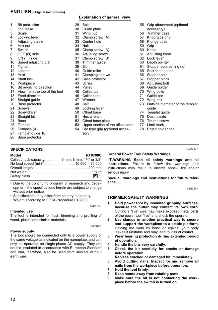
Straight bit
Rechte frezen
IOI KOITIKO
Fraise à rainer
Fresa recta
Duzuc
Nutfraser
Fresa direita
Fresa a refilo
Notfærser
mm
| D | A | L1 | L2 | |
| 20 | 6 | 20 | 50 | 15 |
| 20E | 1/4" | |||
| 8 | 8 | 8 | 60 | 25 |
| 8 | 6 | 50 | 18 | |
| 8E | 1/4" | |||
| 6 | 6 | 6 | 50 | 18 |
| 6E | 1/4" |
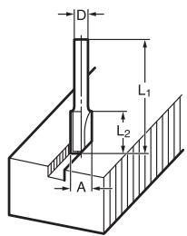
"U" Grooving bit
U-groef freeze
Kottikó yia
aúkawμa "U"
Kottikó yia
aúkawuá “V”
Drill point flush trimming bit
KoTTIKO KOUPEmuOg ME KEPAaN TpuTAVIOU
Fraise à affleurer
Fresa simple para paneles
μεκεφαλ
Bündigfräser
Ball bearing flush trimming bit
Ball bearing corner rounding bit
Ball bearing cham-fering bit
Ball bearing beading bit