
T973 - Audio Amplifier NAD - Free user manual and instructions
Find the device manual for free T973 NAD in PDF.
| Product type | Multi-channel power amplifier |
| Number of channels | 7 |
| Output power (8 ohms) | 120 W per channel |
| Output power (4 ohms) | 180 W per channel |
| Minimum speaker impedance | 4 ohms |
| Frequency response | 20 Hz - 20 kHz |
| Total harmonic distortion | < 0.03 % |
| Technology | PowerDrive, Soft Clipping, Class A input amplification |
| Inputs | 7 RCA line inputs |
| Speaker outputs | 7 pairs of binding posts (banana plugs and spades accepted) |
| Special features | 12 V trigger input, Soft Clipping, thermal and short-circuit protection |
| Dimensions (W x H x D) | 435 x 140 x 350 mm |
| Weight | 18 kg |
| Mains power | 230 V / 50 Hz (or 115 V depending on version) |
| Power consumption | 600 W (max) |
| Maintenance | Clean with a soft, dry cloth. Do not use solvents. |
| Safety | Protection fuse, over-temperature and short-circuit protection |
| Spare parts / Repairability | Contact an authorized NAD dealer for spare parts and repairs. |
Frequently Asked Questions - T973 NAD
User questions about T973 NAD
0 question about this device. Answer the ones you know or ask your own.
Ask a new question about this device
Download the instructions for your Audio Amplifier in PDF format for free! Find your manual T973 - NAD and take your electronic device back in hand. On this page are published all the documents necessary for the use of your device. T973 by NAD.
USER MANUAL T973 NAD
Seven Channel Power Amplifier
GB Owner's Manual
IMPORTANT SAFETY INSTRUCTIONS


CAUTION: TO REDUCE THE RISK OF ELECTRIC SHOCK, DO NOT REMOVE COVER (OR BACK). NO USER SERVICEABLE PARTS INSIDE. REFER SERVICING TO QUALIFIED SERVICE PERSONNEL.
Warning: To reduce the risk of fire or electric shock, do not expose this unit to rain or moisture.
The lightning flash with an arrowhead symbol within an equilateral triangle, is intended to alert the user to the presence of uninsulated "dangerous voltage" within the product's enclosure that may be of sufficient magnitude to constitute a risk of electric shock to persons.

The exclamation point within an equilateral triangle is intended to alert the user to the presence of important operating and maintenance (servicing) instructions in the literature accompanying the product.

Do not place this unit on an unstable cart, stand or tripod, bracket or table. The unit may fall, causing serious injury to a child or adult and serious damage to the unit. Use only with a cart, stand, tripod, bracket or table recommended by the manufacturer or sold with the unit. Any mounting of the device on a wall or ceiling should follow the manufacturer's instructions and should use a mounting accessory recommended by the manufacturer.
An appliance and cart combination should be moved with care. Quick stops, excessive force and uneven surfaces may cause the appliance and cart combination to overturn.
Read and follow all the safety and operating instructions before connecting or using this unit. Retain this notice and the owner's manual for future reference.
All warnings on the unit and in its operating instructions should be adhered to.
Do not use this unit near water; for example, near a bath tub, washbowl, kitchen sink, laundry tub, in a wet basement or near a swimming pool.
The unit should be installed so that its location or position does not interfere with its proper ventilation. For example, it should not be situated on a bed, sofa, rug or similar surface that may block the ventilation openings; or placed in a built-in installation, such as a bookcase or cabinet, that may impede the flow of air through its ventilation openings.
The unit should be situated from heat sources such as radiators, heat registers, stoves or other devices (including amplifiers) that produce heat.
The unit should be connected to a power supply outlet only of the voltage and frequency marked on its rear panel.
The power supply cord should be routed so that it is not likely to be walked on or pinched, especially near the plug, convenience receptacles, or where the cord exits from the unit.
Unplug the unit from the wall outlet before cleaning. Never use benzine, thinner or other solvents for cleaning. Use only a soft damp cloth.
The power supply cord of the unit should be unplugged from the wall outlet when it is to be unused for a long period of time.
Care should be taken so that objects do not fall, and liquids are not spilled into the enclosure through any openings.
This unit should be serviced by qualified service personnel when:
A. The power cord or the plug has been damaged; or
B. Objects have fallen, or liquid has been spilled into the unit; or C. The unit has been exposed to rain or liquids of any kind; or
D. The unit does not appear to operate normally or exhibits a marked change in performance; or
E. The device has been dropped or the enclosure damaged.
DO NOT ATTEMPT SERVICING OF THIS UNIT YOURSELF. REFER SERVICING TO QUALIFIED SERVICE PERSONNEL
Upon completion of any servicing or repairs, request the service shop's assurance that only Factory Authorized Replacement Parts with the same characteristics as the original parts have been used, and that the routine safety checks have been performed to guarantee that the equipment is in safe operating condition. REPLACEMENT WITH UNAUTHORIZED PARTS MAY RESULT IN FIRE, ELECTRIC SHOCK OR OTHER HAZARDS.
ATTENTION
POUR ÉVITER LES CHOC ELECTRIQUES, INTRODUIRE LA LAME LA PLUS LARGE DE LA FICHE DANS LA BORNE CORRESPONDANTE DE LA PRISE ET POUSSER JUSQU'AU FOND.
CAUTION
TO PREVENT ELECTRIC SHOCK, MATCH WIDE BLADE OF PLUG TO WIDE SLOT FULLY INSERT.
If an indoor antenna is used (either built into the set or installed separately), never allow any part of the antenna to touch the metal parts of other electrical appliances such as a lamp, TV set etc.
CAUTION POWER LINES
Any outdoor antenna must be located away from all power lines.
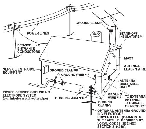
OUTDOOR ANTENNA GROUNDING
If an outside antenna is connected to your tuner or tuner-preamplifier, be sure the antenna system is grounded so as to provide some protection against voltage surges and built-up static charges. Article 810 of the National Electrical Code, ANSI/NFPA No. 70-1984, provides information with respect to proper grounding of the mast and supporting structure, grounding of the lead-in wire to an antenna discharge unit, size of grounding conductors, location of antenna discharge unit, connection to grounding electrodes and requirements for the grounding electrode.
a. Use No. 10 AWG (5.3mm2) copper, No. 8 AWG (8.4mm2) aluminium, No. 17 AWG (1.0mm2) copper-clad steel or bronze wire, or larger, as a ground wire.
b. Secure antenna lead-in and ground wires to house with stand-off insulators spaced from 4-6 feet (1.22 - 1.83 m) apart.
c. Mount antenna discharge unit as close as possible to where lead-in enters house.
d. Use jumper wire not smaller than No.6 AWG (13.3mm2) copper, or the equivalent, when a separate antenna-grounding electrode is used. see NEC Section 810-21 (j).
EXAMPLE OF ANTENNA GROUNDING AS PER NATIONAL ELECTRICAL CODE INSTRUCTIONS CONTAINED IN ARTICLE 810 - RADIO AND TELEVISION EQUIPMENT.
NOTE TO CATV SYSTEM INSTALLER: This reminder is provided to call the CATV system installer's attention to Article 820-40 of the National Electrical Code that provides guidelines for proper grounding and, in particular, specifies that the ground cable ground shall be connected to the grounding system of the building, as close to the point of cable entry as practical.
NOTES ON ENVIRONMENTAL PROTECTION
At the end of its useful life, this product must not be disposed of with regular household waste but must be returned to a collection point for the recycling of electrical and electronic equipment. The symbol on the product, user's manual and packaging, point this out.
The materials can be reused in accordance with their markings. Through re-use, recycling of raw materials, or other forms of recycling of old products, you are making an important contribution to the protection of our environment.
Your local administrative office can advise you of the responsible waste disposal point.

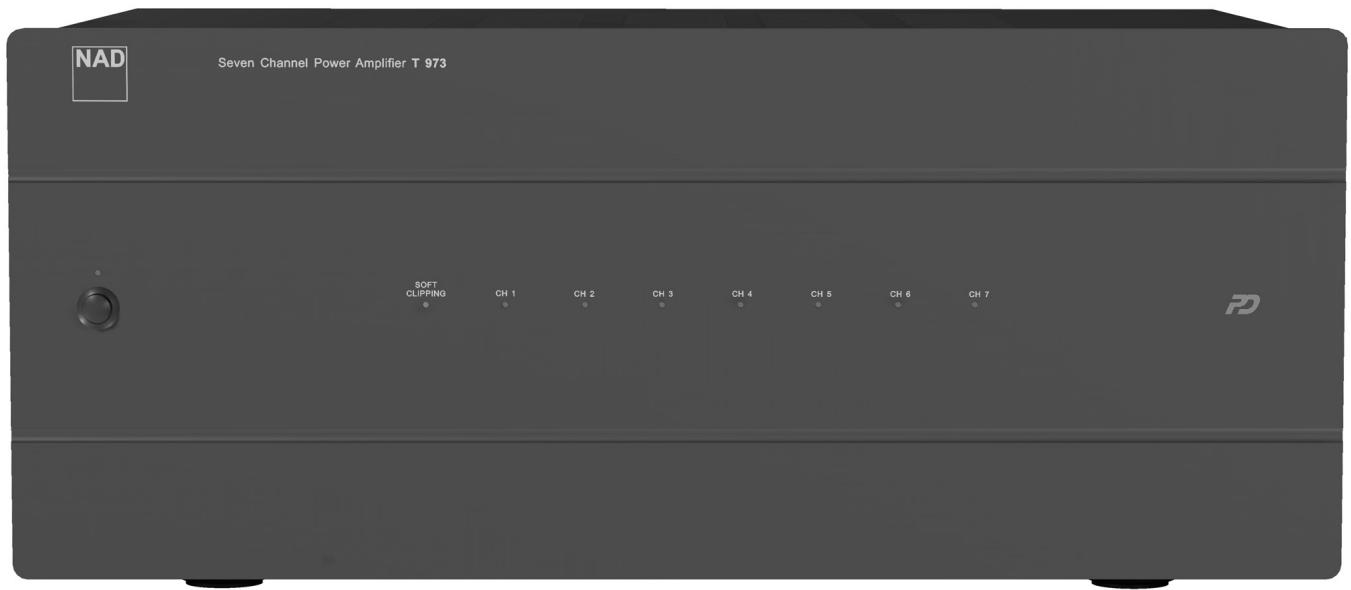
FRONT PANEL CONTROLS
REAR PANEL CONNECTIONS
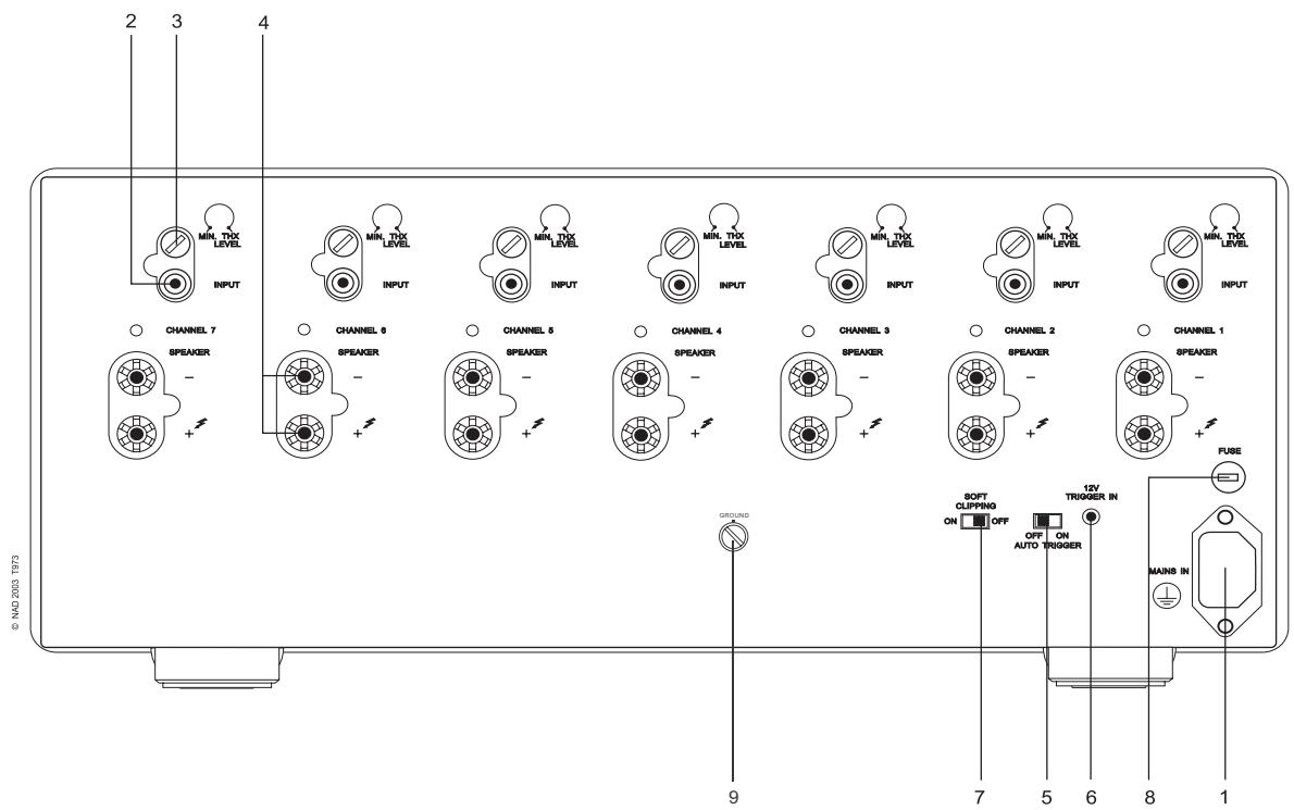
FIGURE 1
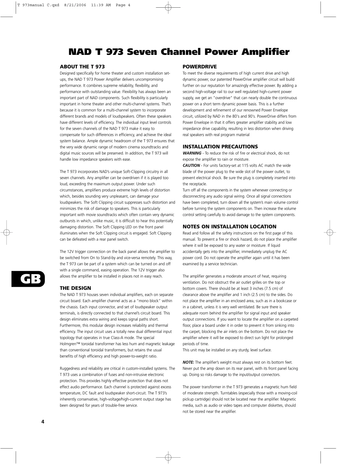
NAD T 973 Seven Channel Power Amplifier
ABOUT THE T 973
Designed specifically for home theater and custom installation set-ups, the NAD T 973 Power Amplifier delivers uncompromising performance. It combines supreme reliability, flexibility, and performance with outstanding value. Flexibility has always been an important part of NAD components. Such flexibility is particularly important in home theater and other multi-channel systems. That's because it is common for a multi-channel system to incorporate different brands and models of loudspeakers. Often these speakers have different levels of efficiency. The individual input level controls for the seven channels of the NAD T 973 make it easy to compensate for such differences in efficiency, and achieve the ideal system balance. Ample dynamic headroom of the T 973 ensures that the very wide dynamic range of modern cinema soundtracks and digital music sources will be preserved. In addition, the T 973 will handle low impedance speakers with ease.
The T 973 incorporates NAD's unique Soft-Clipping circuitry in all seven channels. Any amplifier can be overdriven if it is played too loud, exceeding the maximum output power. Under such circumstances, amplifiers produce extreme high levels of distortion which, besides sounding very unpleasant, can damage your loudspeakers. The Soft Clipping circuit suppresses such distortion and minimizes the risk of damage to speakers. This is particularly important with movie soundtracks which often contain very dynamic outbursts in which, unlike music, it is difficult to hear this potentially damaging distortion. The Soft Clipping LED on the front panel illuminates when the Soft Clipping circuit is engaged. Soft Clipping can be defeated with a rear panel switch.
The 12V trigger connection on the back panel allows the amplifier to be switched from On to Stand-by and vice-versa remotely. This way, the T 973 can be part of a system which can be turned on and off with a single command, easing operation. The 12V trigger also allows the amplifier to be installed in places not in easy reach.
THE DESIGN
The NAD T 973 houses seven individual amplifiers, each on separate circuit board. Each amplifier channel acts as a "mono block" within the chassis. Each input connector, and set of loudspeaker output terminals, is directly connected to that channel's circuit board. This design eliminates extra wiring and keeps signal paths short. Furthermore, this modular design increases reliability and thermal efficiency. The input circuit uses a totally new dual differential input topology that operates in true Class-A mode. The special Holmgren™ toroidal transformer has less hum and magnetic leakage than conventional toroidal transformers, but retains the usual benefits of high efficiency and high power-to-weight ratio.
Ruggedness and reliability are critical in custom-installed systems. The T 973 uses a combination of fuses and non-intrusive electronic protection. This provides highly effective protection that does not effect audio performance. Each channel is protected against excess temperature, DC fault and loudspeaker short-circuit. The T 973's inherently conservative, high-voltage/high-current output stage has been designed for years of trouble-free service.
POWERDRIVE
To meet the diverse requirements of high current drive and high dynamic power, our patented PowerDrive amplifier circuit will build further on our reputation for amazingly effective power. By adding a second high-voltage rail to our well regulated high-current power supply, we get an "overdrive" that can nearly double the continuous power on a short term dynamic power basis. This is a further development and refinement of our renowned Power Envelope circuit, utilized by NAD in the 80's and 90's. PowerDrive differs from Power Envelope in that it offers greater amplifier stability and low impedance drive capability, resulting in less distortion when driving real speakers with real program material
INSTALLATION PRECAUTIONS
WARNING - To reduce the risk of fire or electrical shock, do not expose the amplifier to rain or moisture.
CAUTION - For units factory-set at 115 volts AC match the wide blade of the power plug to the wide slot of the power outlet, to prevent electrical shock. Be sure the plug is completely inserted into the receptacle.
Turn off all the components in the system whenever connecting or disconnecting any audio signal wiring. Once all signal connections have been completed, turn down all the system's main volume control before turning the system components on. Then increase the volume control setting carefully to avoid damage to the system components.
NOTES ON INSTALLATION LOCATION
Read and follow all the safety instructions on the first page of this manual. To prevent a fire or shock hazard, do not place the amplifier where it will be exposed to any water or moisture. If liquid accidentally gets into the amplifier, immediately unplug the AC power cord. Do not operate the amplifier again until it has been examined by a service technician.
The amplifier generates a moderate amount of heat, requiring ventilation. Do not obstruct the air outlet grilles on the top or bottom covers. There should be at least 3 inches (7.5 cm) of clearance above the amplifier and 1 inch (2.5 cm) to the sides. Do not place the amplifier in an enclosed area, such as in a bookcase or in a cabinet, unless it is very well ventilated. Be sure there is adequate room behind the amplifier for signal input and speaker output connections. If you want to locate the amplifier on a carpeted floor, place a board under it in order to prevent it from sinking into the carpet, blocking the air inlets on the bottom. Do not place the amplifier where it will be exposed to direct sun light for prolonged periods of time.
This unit may be installed on any sturdy, level surface.
NOTE: The amplifier's weight must always rest on its bottom feet. Never put the amp down on its rear panel, with its front panel facing up. Doing so risks damage to the input/output connectors.
The power transformer in the T 973 generates a magnetic hum field of moderate strength. Turntables (especially those with a moving-coil pickup cartridge) should not be located near the amplifier. Magnetic media, such as audio or video tapes and computer diskettes, should not be stored near the amplifier.

REAR PANEL CONNECTIONS/CONTROLS
1. AC LINE CORD
Plug the AC line cord into a nearby wall outlet that provides the correct AC power line voltage, as indicated on the back panel of the unit. Do not plug the amplifier into a convenience outlet on your preamp. The amplifier requires more power than these outlets typically can provide.
2. INPUTS
Each of the seven independent power amplifiers within the T 973 has its own signal input connector. Before making any connections to the amplifier, make sure the POWER is switched OFF.
Connect the signal cables from the preamplifier, surround sound decoder, or other signal source to these inputs. For optimum heat dissipation in an AV surround system, we recommend you allocate the audio channels to the inputs as follows:
Input 1 = Right Main speaker
Input 2 = Right surround speaker
Input 3 = Center speaker
Input 4 = Left Surround speaker
Input 5 = Left Main speaker
Input 6 = Left Surround Rear speaker
Input 7 = Right Surround Rear speaker
3. INPUT LEVEL CONTROLS
The amplifier is equipped with separate input level controls for each channel. Before turning on the T 973 for the first time, make sure all level controls are in their normal full-clockwise position.
Under some circumstances, other settings may be useful for:
- Level-matching - In systems that incorporate speakers of varying efficiencies, it may be necessary to reduce the settings of some controls to achieve proper channel-to-channel balance.
- Extended volume-control range - Many stereo systems have so much voltage gain that the speakers (or your ears) are over-driven at any volume-control setting higher than 11 or 12 o'clock position of the volume control. As a result you can use only the lower half of the volume control's range, where adjustments are imprecise and channel-balance errors tend to be greater. If all input level controls are reduced, you can turn up your preamplifier's volume control, making effective use of most of its range. (Suggestion: Adjust the input level controls so that your preferred maximum sound levels occur at about 2 or 3 o'clock on the volume control.) As an added benefit, this procedure suppresses any noise produced by the preamp's high-level circuitry (e.g. any residual hum or hiss that does not go away when the Volume is turned down).
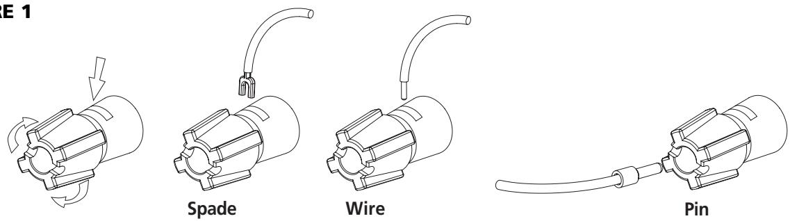
4. SPEAKER CONNECTIONS
This amplifier is equipped with special high-current binding-post speaker terminals. Connect the loudspeakers with heavy-duty (16-gauge or thicker) braided wire. Connections may be made in any of three ways. [See Figure 1.]
- Strip off a half-inch (1 cm) of insulation from each speaker wire. In each conductor, twist the thin strands of wire together.
Unscrew the knob, insert the bare wire into the opening at the base of the binding post, and tighten the knob until it grasps the wire securely. Check to be sure that there are no loose strands of
wire touching the chassis or an adjacent terminal.
- Spade lugs. Unscrew the knob, insert the U-shaped spade lug behind the bushing, and tighten the knob until the spade lug is secured.
- Install banana plugs on your speaker wires, and plug them into the end of each binding post. The terminals are separated by 3/4 inch (19mm), so they will accept dual-banana plugs (this option is not available on units with 230V line voltage factory setting).
NOTE: Speakers must operate in phase with each other in order to produce a proper stereo image and to reinforce rather than cancel each other's output at low frequencies. When connecting speakers, take care that the red (positive) terminal on each loudspeaker is connected to the corresponding terminal marked red (positive) on the amplifier.
5. AUTO TRIGGER ON/OFF
Set the Auto Trigger switch to the On position to activate the 12V-trigger. By connecting the 12V-trigger, the T 973 can be remotely switched to On and Stand-by and vice-versa. When set to the Off position, the 12V-trigger input is not active.
NOTE: With the Auto Trigger switch set to the ON position and the 12V-trigger input connected, the T 973 will switch from Off to Stand-by when the Power Switch on the front panel is pressed. For normal operation, ensure the switch is in the OFF position or that the 12V-trigger input socket is not connected.
6. 12V-TRIGGER INPUT
For external Power on/Stand-by switching, connect the 12V-trigger output of a source component to this DC input jack. The center pin is the live or + connection, the outer sleeve of the input jack is the 12V-trigger - or ground connection.
NOTES: The T 973's 12V-trigger will work within a range of 6 to 15 V DC level and typically draws less than 10mA of current. Check the specifications of the 12V-trigger source to ensure it is compatible with the T 973's 12V-trigger input. Do not exceed the recommended voltage as this may cause damage to the T 973.
7. SOFT CLIPPING
When an amplifier is driven beyond its specified power output it normally produces “hard clipping” or distortion of the signal. Such hard clipping, in addition to sounding unpleasant, can damage the speakers in the system. The NAD Soft Clipping circuit gently limits the output waveform, minimizing audible distortion and reducing the change of speaker damage when the amplifier is overdriven. We recommend that the Soft Clipping switch on the back panel of the T 973 be left in the ON position when system is being operated at levels that might exceed the amplifier’s power capacity. The LED on the front panel indicates if Soft Clipping has been engaged.
8. FUSE HOLDER
There is a fuse holder nearby or next to the AC-line cord. In the unlikely event a fuse may need to be replaced, unplug the line cord form the wall. Then remove all connections from the amplifier. Only replace the fuse with the same type, size, and specification.
9. GROUND CONNECTOR
The T 973 is provided with a GROUND terminal on the rear panel. This terminal is connected directly to the chassis of the T 973. In the event of radio hum or radio interference, this terminal can be connected to a 'true earth' such as a copper plated rod driven several feet into the ground.
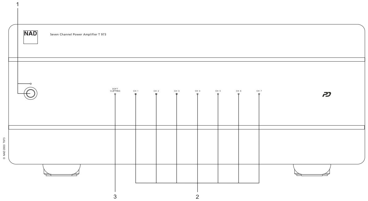
FRONT PANEL CONTROLS
1. POWER SWITCH/STAND-BY LED
Press this button to switch the amplifier on or off. The Power LED located just above the power button and Protection LED will light up. After a few seconds, the Protection LED (2) will turn green, indicating that the amplifier is ready for use.
The T 973 can also be remotely switched from On to Stand-by and vice-versa using the 12V-trigger input on the back panel. For the 12V-trigger input to work, the T 973 must first be turned on by means of the Power switch, and the switch must be left in this position. Using the 12V-trigger source component, switch its 12V-trigger output to on and off. The T 973's trigger input will now follow the source component's 12V-trigger output. Ensure that the Auto Trigger switch on the back panel is in the ON position and that the 12V-trigger input is connected properly.
2. PROTECTION LED
The Protection LED will light up every time the amplifier is switched on. After a few seconds it will turn green and the amplifier is ready for operation.
These LEDs will also come on when one or more of the internal seven amplifiers go into protect mode, but the other amplifiers will continue to function so it is likely you will still hear sound.
When the amplifier is switched off completely from normal operation by means of the power switch, the Protection LEDs will light up and will fade out in a couple of seconds.
NOTE: If you see the Protection LED light up during use, turn off the amplifier immediately. Check if all speaker wires are connected correctly and that none of the wires are damaged, causing a short circuit. Another cause may be excessive heat build-up inside the amplifier. Make sure there is adequate ventilation around the amplifier and that none of its ventilation slots, top or bottom, are blocked. After the amplifier has cooled down, it will function normally again.
In case the Protection LED remains on despite the checks mentioned above, turn the amplifier off and consult your NAD dealer.
3. SOFT CLIPPING LIGHTS
When the Soft Clipping circuit of the T 973 is activated the indicator LED's on the front panel will light.

TROUBLESHOOTING
| PROBLEM | CAUSE | SOLUTION |
| NO SOUND | Power AC lead unplugged or power not switched on | Check if AC lead is plugged in and power switched on |
| NO SOUND ON ONE CHANNEL | Speaker not properly connected or damaged.Input lead disconnected or damaged | Check connections and speakersCheck leads and connections |
| NO SOUND ON SURROUND CHANNELS | No surround mode selectedMono sound sourceSpeakers not properly connectedSurround volume level too low | Select a Surround ModeTest system with Stereo or Dolby Surround materialCheck speakers and connectionsIncrease surround volume level |
| NO SOUND ON CENTER CHANNEL | Speaker not connected properlyCenter volume level set too low | Check speaker and connectionIncrease center volume level |
| WEAK BASS/ DIFFUSE STEREO IMAGE | Speakers wired out of phase | Check connections to all speakers in the system |
| TEMPORARILY SWITCHES TO STANDBY, THEN SWITCHES BACK ON AUTOMATICALLY | Amplifier is running too hot | Let the amplifier cool downRemove the excessive load conditionSpeakers must be greater than 4 Ohms nominal |
3. LUCI "SOFT CLIPPING"
www.NADelectronics.com
©2003 NAD ELECTRONICS INTERNATIONAL
All rights reserved. No part of this publication may be reproduced, stored or transmitted in any form without the written permission of NAD Electronics International
T 973 Manual 10/2003 Printed in China
- Seven Channel Power Amplifier
- IMPORTANT SAFETY INSTRUCTIONS
- DO NOT ATTEMPT SERVICING OF THIS UNIT YOURSELF. REFER SERVICING TO QUALIFIED SERVICE PERSONNEL
- ATTENTION
- CAUTION
- CAUTION POWER LINES
- OUTDOOR ANTENNA GROUNDING
- NOTES ON ENVIRONMENTAL PROTECTION
- NAD T 973 Seven Channel Power Amplifier
- ABOUT THE T 973
- THE DESIGN
- POWERDRIVE
- INSTALLATION PRECAUTIONS
- NOTES ON INSTALLATION LOCATION
- REAR PANEL CONNECTIONS/CONTROLS
- AC LINE CORD
- INPUTS
- INPUT LEVEL CONTROLS
- SPEAKER CONNECTIONS
- AUTO TRIGGER ON/OFF
- 12V-TRIGGER INPUT
- SOFT CLIPPING
- FUSE HOLDER
- GROUND CONNECTOR
- FRONT PANEL CONTROLS
- POWER SWITCH/STAND-BY LED
- PROTECTION LED
- SOFT CLIPPING LIGHTS
- LUCI "SOFT CLIPPING"
- ©2003 NAD ELECTRONICS INTERNATIONAL
Brand : NAD
Model : T973
Category : Audio Amplifier