
911 - Audio Amplifier NAD - Free user manual and instructions
Find the device manual for free 911 NAD in PDF.

| Product Type | Multi-zone audio distribution preamplifier |
| Brand | NAD |
| Model | 911 |
| Number of channels | 6 (independent, with individual level control) |
| Audio inputs | 6 RCA line inputs (channels 1-6), 1 1/4" mic input, 1 RCA line insert input |
| Audio outputs | 6 fixed RCA outputs, 6 variable RCA outputs, 1 RCA mic line output |
| Power supply | Mains (detachable power cord) |
| Dimensions (W x H x D) | 482 x 88 x 254 mm (19" rack format, 2U) |
| Weight | 4.5 kg |
| Microphone function | Mic input with noise filter and limiter, level control, global or per-channel insert |
| Insert function | Allows inserting mic or line signal on selected channels, with fixed, variable or disabled per jumper options |
| Channel interconnection | Possibility to link fixed outputs to inputs of following channels for music signal distribution |
| Controls | Channel level (potentiometer), mic level (potentiometer), push-button insert |
| Internal configuration options | Jumpers for fixed/variable mic level, fixed/variable/disabled per-channel insert, fixed/variable mic line output |
| Tamper protection | Removable covers provided to conceal level controls and/or insert buttons |
| Maintenance and cleaning | Clean with a damp cloth (soapy water), do not use solvents |
| Safety precautions | Place on a flat, rigid surface, avoid moisture, unplug if liquid spills, internal servicing by qualified personnel only |
| Recommended use | With hi-fi preamplifier for background music and voice announcements in multi-zone setups |
| Amplifier compatibility | Hi-fi or professional amplifiers (variable output up to 20 dBu / 600 ohms) |
| Recommended cables | Quality coaxial signal cables, speaker cables at least 16 AWG |
Frequently Asked Questions - 911 NAD
User questions about 911 NAD
0 question about this device. Answer the ones you know or ask your own.
Ask a new question about this device
Download the instructions for your Audio Amplifier in PDF format for free! Find your manual 911 - NAD and take your electronic device back in hand. On this page are published all the documents necessary for the use of your device. 911 by NAD.
USER MANUAL 911 NAD
IMPORTANT SAFETY INSTRUCTIONS


CAUTION: TO REDUCE THE RISK OF ELECTRIC SHOCK, DO NOT REMOVE COVER (OR BACK). NO USER SERVICEABLE PARTS INSIDE. REFER SERVICING TO QUALIFIED SERVICE PERSONNEL.
Warning: To reduce the risk of fire or electric shock, do not expose this unit to rain or moisture.

The lightning flash with an arrowhead symbol within an equilateral triangle, is intended to alert the user to the presence of uninsulated “dangerous voltage” within the product’s enclosure that may be of sufficient magnitude to constitute a risk of electric shock to persons.

The exclamation point within an equilateral triangle is intended to alert the user to the presence of important operating and maintenance (servicing) instructions in the literature accompanying the product.

Do not place this unit on an unstable cart, stand or tripod, bracket or table. The unit may fall, causing serious injury to a child or adult and serious damage to the unit. Use only with a cart, stand, tripod, bracket or table recommended by the manufacturer or sold with the unit. Any mounting of the device on a wall or ceiling should follow the manufacturer's instructions and should use a mounting accessory recommended by the manufacturer.
An appliance and cart combination should be moved with care. Quick stops, excessive force and uneven surfaces may cause the appliance and cart combination to overturn.
Read and follow all the safety and operating instructions before connecting or using this unit. Retain this notice and the owner's manual for future reference. All warnings on the unit and in it's operating instructions should be adhered to.
Do not use this unit near water; for example, near a bath tub, washbowl, kitchen sink, laundry tub, in a wet basement or near a swimming pool.
The unit should be installed so that its location or position does not interfere with its proper ventilation. For example, it should not be situated on a bed, sofa, rug or similar surface that may block the ventilation openings; or placed in a built-in installation, such as a bookcase or cabinet, that may impede the flow of air through its ventilation openings.
The unit should be situated from heat sources such as radiators, heat registers, stoves or other devices (including amplifiers) that produce heat.
The unit should be connected to a power supply outlet only of the voltage and frequency marked on its rear panel.
The power supply cord should be routed so that it is not likely to be walked on or pinched, especially near the plug, convenience receptacles, or where the cord exits from the unit.
Unplug the unit from the wall outlet before cleaning. Never use benzine, thinner or other solvents for cleaning. Use only a soft damp cloth.
The power supply cord of the unit should be unplugged from the wall outlet when it is to be unused for a long period of time.
Care should be taken so that objects do not fall, and liquids are not spilled into the enclosure through any openings.
This unit should be serviced by qualified service personnel when:
A. The power cord or the plug has been damaged; or
B. Objects have fallen, or liquid has been spilled into the unit; or
C. The unit has been exposed to rain or liquids of any kind; or
D. The unit does not appear to operate normally or exhibits a marked change in performance; or
E. The device has been dropped or the enclosure damaged.
DO NOT ATTEMPT SERVICING OF THIS UNIT YOURSELF. REFER SERVICING TO QUALIFIED SERVICE PERSONNEL.
Upon completion of any servicing or repairs, request the service shop's assurance that only Factory Authorized Replacement Parts with the same characteristics as the original parts have been used, and that the routine safety checks have been performed to guarantee that the equipment is in safe operating condition.
REPLACEMENT WITH UNAUTHORIZED PARTS MAY RESULT IN FIRE, ELECTRIC SHOCK OR OTHER HAZARDS.
ATTENTION
POUR ÉVITER LES CHOC ELECTRIQUES, INTRODUIRE LA LAME LA PLUS LARGE DE LA FICHE DANS LA BORNE CORRESPONDANTE DE LA PRISE ET POUSSER JUSQU'AU FOND.
CAUTION
TO PREVENT ELECTRIC SHOCK MATCH WIDE BLADE OF PLUG TO WIDE SLOT FULLy INSERT.
If an indoor antenna is used (either built into the set or installed separately), never allow any part of the antenna to touch the metal parts of other electrical appliances such as a lamp, TV set etc.
CAUTION
POWER LINES
Any outdoor antenna must be located away from all power lines.
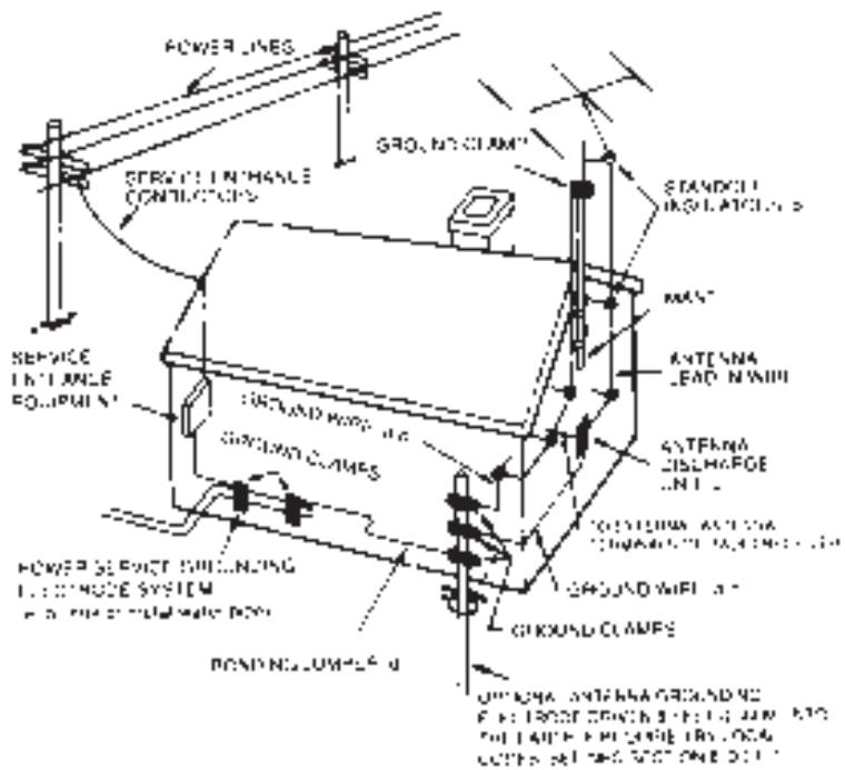
OUTDOOR ANTENNA GROUNDING
If an outside antenna is connected to your tuner or tuner-preamplifier, be sure the antenna system is grounded so as to provide some protection against voltage surges and built-up static charges. Section 810 of the National Electrical Code, ANSI/NFPA No. 70-1984, provides information with respect to proper grounding of the mast and supporting structure, grounding of the lead-in wire to an antenna discharge unit, size of grounding conductors, location of antenna discharge unit, connection to grounding electrodes and requirements for the grounding electrode.
a. Use No. 10 AWG (5.3mm2) copper, No. 8 AWG (8.4mm2) aluminium, No. 17 AWG (1.0mm2) copper-clad steel or bronze wire, or larger, as a ground wire.
b. Secure antenna lead-in and ground wires to house with stand-off insulators spaced from 4-6 feet (1.22 - 1.83 m) apart.
c. Mount antenna discharge unit as close as possible to where lead-in enters house.
d. Use jumper wire not smaller than No.6 AWG (13.3mm2) copper, or the equivalent, when a separate antenna-grounding electrode is used. see NEC Section 810-21 (j).
EXAMPLE OF ANTENNA GROUNDING AS PER NATIONAL ELECTRICAL CODE INSTRUCTIONS CONTAINED IN ARTICLE 810 - RADIO AND TELEVISION EQUIPMENT.
NOTE TO CATV SYSTEM INSTALLER: This reminder is provided to call the CATV system installer's attention to Article 820-22 of the National Electrical Code that provides guidelines for proper grounding and, in particular, specifies that the ground cable ground shall be connected to the grounding system of the building, as close to the point of cable entry as practical.
REAR PANEL CONNECTIONS
FRONT PANEL CONTROLS
INTRODUCTION TO THE NAD-911 DIS- TRIBUTION PREAMPLIFIER.
The NAD-911 Distribution Preamplifier has been designed to control sound in multi-room or multi-speaker installations where both music and messaging is required. It will take mono or stereo signals from a mixer or hi-fi preamplifier and control the distribution of sound in up to six separately controllable speaker zones. Each level control will alter the volume of one particular speaker zone so that the system can deliver music at different levels in different areas of the installation. With the built-in microphone section, the NAD-911 can selectively deliver announcements and messages to individual parts of the system.
Several NAD-911s can be connected together to control music and messages in larger installations. With a range of internal configuration presets, the NAD-911 has the flexibility to be configured to match the needs of most setups.
This manual outlines the use of the NAD-911 in the most common types of installation. The unit can also be configured for a wide range of specialist setups and a qualified installation engineer will be able to advise on connecting and configuring the NAD-911 within more complex installations.
IMPORTANT INFORMATION.
The NAD-911 should be placed on a firm level surface. Dampness can damage electronic components, so the unit should not be placed in areas of high humidity or where liquid could be splashed on it or spilt over it.
If liquid is spilt over the unit then disconnect from the AC socket and have the unit inspected by qualified service personnel before attempting to use it again.
The NAD-911 uses standard RCA and 1/4" jack connections and it is recommended that you use high quality connectors and cables throughout the installation as this will improve the reliability and the overall performance of the system.
If the unit is not going to be used for some time, disconnect the power plug from the AC socket.
There are installation presets inside the unit and these should be adjusted by qualified installation personnel only. Ensure the top cover is securely replaced before using your NAD Distribution Preamplifier.
CLEANING.
Use a soft cloth to clean the NAD-911. If necessary, lightly dampen the cloth with soapy water. Do not use solutions containing benzol or other volatile agents.
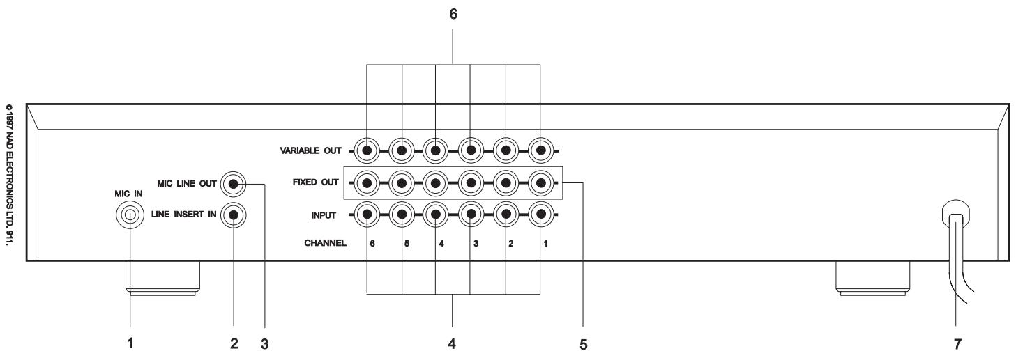
REAR PANEL CONNECTIONS.
1.MIC IN
Input for a Microphone. This Input is suitable for most medium to high impedance microphones.
The microphone circuitry has a bass roll-off filter that will reduce low frequency microphone handling noises being passed to the speakers. A limiter has been added to the microphone circuit to reduce overload distortion on very loud sounds. The Microphone is selected by using the front panel MASTER INSERT button (6) together with the individual channel INSERT buttons (4) and adjusting MICROPHONE LEVEL control (5). Plugging in a microphone into this socket automatically switches off the LINE INSERT IN connector.
2.LINE INSERT IN
Input for a line level source. This is used as an alternative to the microphone for message sources such as pre-recorded announcements. This is only active when MIC IN is unused. The MIC IN and LINE INSERT IN signal can be at a fixed or variable level depending on the settings of the internal configuration presets.
3.MIC LINE OUT
Direct output for the microphone signal. The NAD-911 amplifies the microphone input to line level so it can be used as the microphone feed to additional NAD-911s in a larger installation. The output of this socket can be at a fixed or variable level depending on the settings of the internal configuration presets.
4. INPUT (CHANNELS 1 -6)
Line level inputs for each of the six channels. These can be connected to any type of audio system such as a hi-fi preamplifier, cassette deck, CD player, mixer or the audio outputs of a video player. For mono sources use a single channel, for stereo sources use two adjacent channels.
5. FIXED OUT (CHANNELS 1-6)
Direct output for each channel. The level of the signal on this connector remains the same regardless of the front panel level controls. The INSERT signal does not appear on the FIXED OUT connections. The level is suitable for driving standard hi-fi components and amplifiers and can be used with leads up to 1nF total capacitance.
6.VARIABLE OUT (CHANNELS 1-6)
Direct output for each channel. The level of the signal on this connector is altered by the front panel LEVEL controls (5). The INSERT signal will appear mixed on the VARIABLE OUT connections when selected by pressing the INSERT buttons. At its higher settings of the LEVEL control, this output will drive professional (20dBu/600ohm) amplifiers. The variable output has a low impedance so it can be used to drive long cable runs up to 22nF total capacitance.
7. POWER CABLE
Fixed power AC cord for connection to AC socket.
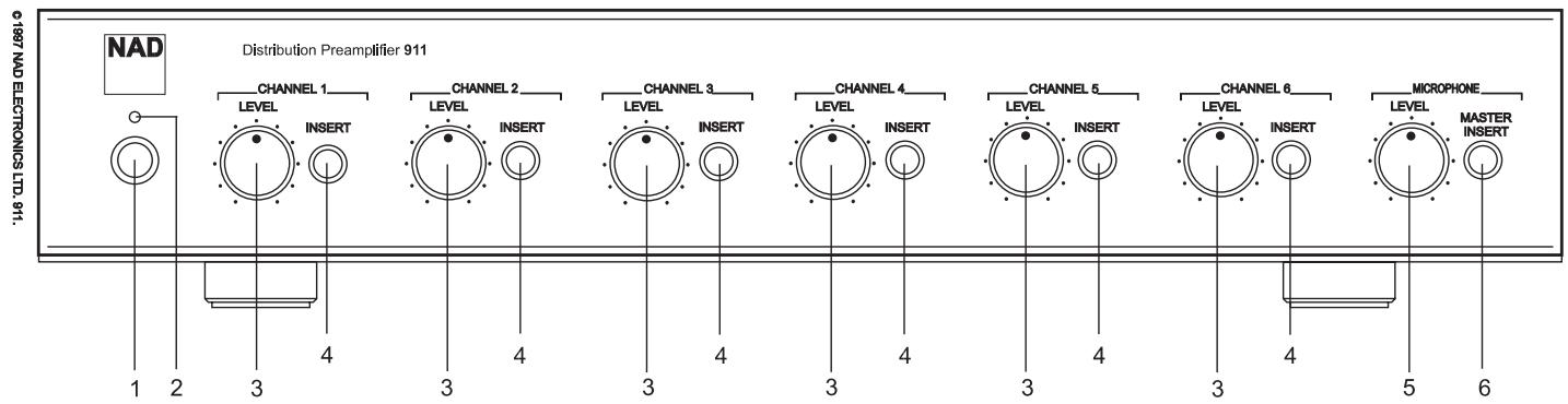
FRONT PANEL CONTROLS.
1. POWER
Power switch to turn the NAD-911 on or off.
2. POWER LED
Indicates that the unit is on.
CHANNELS 1 - 6.
3.LEVEL
Adjusts the volume of each individual speaker channel.
4. INSERT
Allows the Insert Signal (MIC IN or LINE INSERT IN) to be included on this particular speaker channel
MICROPHONE.
5.LEVEL
Adjusts the overall volume of the Insert signal from the MIC IN or LINE INSERT IN sockets.
6.MASTER INSERT
Press to switch the Insert signal on. Press out to completely disable the Insert signal on all channels.
PREAMPLIFIERS, AMPLIFIERS AND MIXERS FOR USE WITH THE NAD-911.
In most installations using the NAD-911, the hi-fi preamplifier is used to select the appropriate music source and for every-day adjustment of the music volume in the venue.
Any hi-fi preamplifier can be used with the NAD-911 or alternatively an integrated hi-fi amplifier can be used providing it has a 'pre-amp' output. NAD supplies a range of preamplifiers and integrated amplifiers suitable for use with the NAD-911.
Some installations will use a mixer instead of a pre-amp and this is connected and used with the NAD-911 in exactly the same way as a preamplifier.
The channel outputs of the NAD-911 will work with both hi-fi and professional power amplifiers. There is a range of NAD single channel, stereo or multi-channel power amplifiers that are suitable to work with the NAD-911.
You should ensure that the power output level of the power amplifiers used in the installation matches the capabilities of the loudspeakers. If you are using a power amplifier with its own volume control, during installation set the NAD-911 LEVEL controls (3) to the 12 O'clock position and then adjust the power amplifier's volume control so that the sound level from the speaker is about right for normal use.
CABLES.
The amplifiers can be placed near the NAD-911 using short signal leads and long speaker leads. Generally you will get better performance from the installation if the amplifiers are placed nearer the speakers using longer signal leads and shorter speaker leads. In either case to achieve best performance all speaker cables should be high quality large diameter speaker cables (16 gauge or more) and all signal leads should be high quality co-axial cable.
Cable lengths of up to 22nF total capacitance can
be used to connect the NAD-911 Variable Output to an amplifier.
flowchart
graph TD
    A["INTEGRATED AMPLIFIER"] --> B["911"]
    B --> C["VIDEO OUT"]
    B --> D["FIXED OUT"]
    B --> E["INPUT"]
    B --> F["CHANNEL 6 5 4 3 2 1"]
    B --> G["MIC IN LINE INSERT IN"]
    B --> H["MIC IN PHONO CD VIDEO SOUND AUX TUNER IN TAPE 2 OUT IN TAPE 1 OUT PRE-OUT IN R L R"]
    style A fill:#f9f,stroke:#333
    style B fill:#ccf,stroke:#333

flowchart
graph TD
    A["LINKING CHANNELS (2 CHANNEL)"] --> B["VARIABLE OUT TO POWER AMPLIFIERS"]
    B --> C["R & L TO NEXT 911"]
    C --> D["FIXED OUT"]
    D --> E["INPUT"]
    E --> F["CHANNEL 6"]
    E --> G["CHANNEL 5"]
    E --> H["CHANNEL 4"]
    E --> I["CHANNEL 3"]
    E --> J["CHANNEL 2"]
    E --> K["CHANNEL 1"]
    style A fill:#f9f,stroke:#333
    style B fill:#ccf,stroke:#333
    style C fill:#cfc,stroke:#333
    style D fill:#fcc,stroke:#333
    style E fill:#cff,stroke:#333
    style F fill:#ffc,stroke:#333
    style G fill:#ffc,stroke:#333
    style H fill:#ffc,stroke:#333
    style I fill:#ffc,stroke:#333
    style J fill:#ffc,stroke:#333
    style K fill:#ffc,stroke:#333
flowchart
graph TD
    A["OUT TO OTHER 911"] --> B["CHANNEL 6"]
    A --> C["CHANNEL 5"]
    A --> D["CHANNEL 4"]
    A --> E["CHANNEL 3"]
    A --> F["CHANNEL 2"]
    A --> G["CHANNEL 1"]
    H["VARIABLE OUT TO POWER AMPLIFIERS"] --> I["CHANNEL 6"]
    H --> J["CHANNEL 5"]
    H --> K["CHANNEL 4"]
    H --> L["CHANNEL 3"]
    H --> M["CHANNEL 2"]
    H --> N["CHANNEL 1"]
    O["FIXED OUT"] --> P["CHANNEL 6"]
    O --> Q["CHANNEL 5"]
    O --> R["CHANNEL 4"]
    O --> S["CHANNEL 3"]
    O --> T["CHANNEL 2"]
    O --> U["CHANNEL 1"]
    V["INPUT"] --> W["CHANNEL 6"]
    V --> X["CHANNEL 5"]
    V --> Y["CHANNEL 4"]
    V --> Z["CHANNEL 3"]
    V --> AA["CHANNEL 2"]
    V --> AB["CHANNEL 1"]
    AC["MONO SIGNAL FROM PRE-AMP"] --> AD["CHANNEL 6"]
    AC --> AE["CHANNEL 5"]
    AC --> AF["CHANNEL 4"]
    AC --> AG["CHANNEL 3"]
    AC --> AH["CHANNEL 2"]
    AC --> AI["CHANNEL 1"]
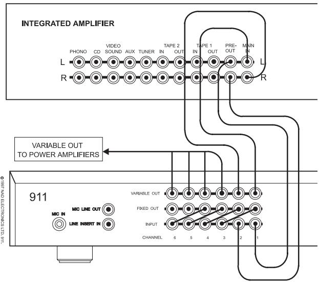
CONNECTING INPUTS.
A simple installation uses a CD player and Cassette Deck connected to the hi-fi preamplifier. In a stereo system the hi-fi preamplifier is connected to INPUT sockets (4) of Channels 1 & 2 of the NAD-911. In a mono system connect the preamplifier to the INPUT of Channel 1 only.
Connect the Microphone to the MIC IN (1).
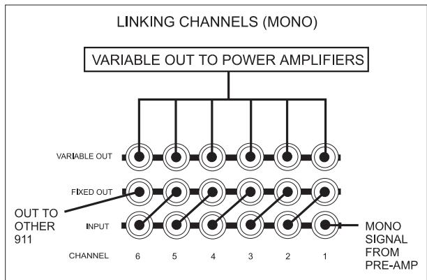
LINKING CHANNELS.
Feeding the music signal to every channel in the distribution preamplifier is done by using links between the outputs of each channel to the inputs of the other channels.
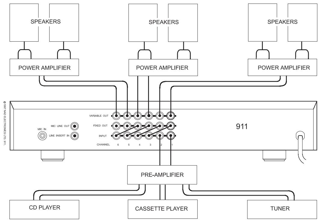
BASIC CONNECTION AND OPERATION.
flowchart
graph TD
    A["SPEAKERS"] --> B["POWER AMPLIFIER"]
    C["SPEAKERS"] --> D["POWER AMPLIFIER"]
    E["SPEAKERS"] --> F["POWER AMPLIFIER"]
    B --> G["911"]
    D --> G
    F --> G
    G --> H["PRE-AMPLIFIER"]
    H --> I["CD PLAYER"]
    H --> J["CASSETTE PLAYER"]
    H --> K["TUNER"]
    G --> L["MIC IN"]
    G --> M["MIC LINE OUT"]
    G --> N["LINE INSERT IN"]
    G --> O["VARIABLE OUT"]
    G --> P["FIXED OUT"]
    G --> Q["INPUT"]
    G --> R["CHANNEL 6 5 4 3 2 1"]
Using the short RCA leads supplied, connect the FIXED OUTPUT (5) of Channels 1 and 2 to the INPUT (4) of Channels 3 & 4. Then connect the FIXED OUTPUT of Channels 3 & 4 to the INPUTs of Channels 5 & 6. (In a mono system connect Channel 1 FIXED OUTPUT to Channel 2 INPUT etc.)
CONNECTING OUTPUTS.
Connect the VARIABLE OUT sockets (6) of each channel to the appropriate power amplifier and speaker system. The power amplifiers and loudspeakers should be matched with respect to power and quality. NAD supplies a range of power and integrated amplifiers suitable for use in these types of installations.
Set the hi-fi preamplifier volume control to minimum. Set the NAD-911 MICROPHONE LEVEL control (5) to minimum and the rest of the Channel LEVEL controls (3) to the 12 O'clock position. Switch the system on.
With a music source playing (preferably a CD) turn the preamplifier volume control up until the music reaches a generally acceptable level. Now adjust each of the individual speaker volumes to exactly the required level by adjusting each of the NAD-911 channel LEVEL controls (3).
SETTING THE MICROPHONE LEVEL.
Switch off the music source. Set the MICROPHONE LEVEL control (5) to minimum. Press the MICROPHONE MASTER INSERT button (6) in and the INSERT buttons (4) on all channels. Speak into the microphone whilst slowly turning up the MICROPHONE LEVEL control (5) until the announcement level is about right. Switch the music source on and fine adjust the MICROPHONE LEVEL. Switch out the MICROPHONE MASTER INSERT button when finished.
BASIC OPERATION.
The NAD-911 is used primarily as an installation tool to distribute and accurately set up the sound levels in all parts of the venue. So in general daily operation, adjust the music source and overall level using the hi-fi preamplifier controls only.
INSERT SIGNAL TO ALL CHANNELS
In a simple installation, where all the channels are linked together, press the INSERT (4) button on all channels. Announcements will be fed to all speakers whenever the microphone is used and the MASTER INSERT button is pressed.
INSERT SIGNAL ONLY ON SELECTED CHANNELS
Press the INSERT buttons (4) only on the channels where announcements are required. Announcements will be fed to those speakers whenever the microphone is used and the MASTER INSERT button is pressed.
Only the channels with the INSERT buttons depressed will be fed with the announcements when the microphone is used and the MASTER INSERT button is pressed. If announcements are to be fed only to specific channels then press the INSERT (4) buttons on only those channels which need announcements.
NOTE:
The microphone Insert signal can be configured internally to be disabled, inserted before or after either one of the six channel level controls. The factory default setting inserts the signal before the level control for all channels. Changing the configuration must be left to qualified personnel.
USING MIC LINE OUT
As well as feeding the Microphone signal internally to each channel using the Insert function, there is a
separate microphone signal output, the MIC LINE OUT (3).
This output carries the microphone signal amplified to line level. It can be used to feed the microphone signal to further external units such as a second NAD-911 or to link in with other separate sound installations.
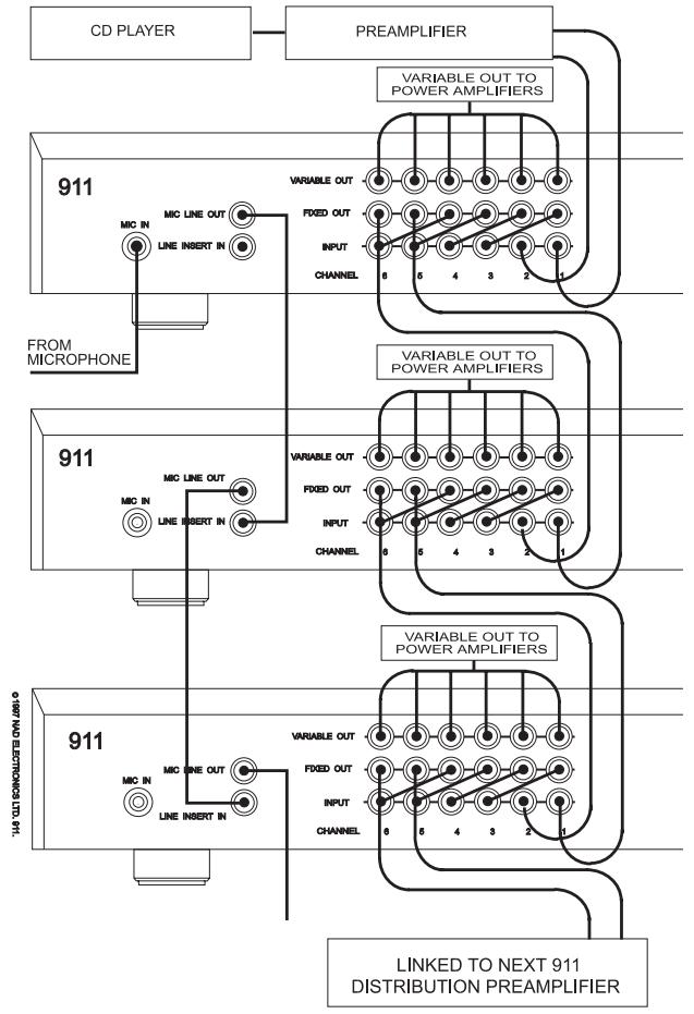
USING SEVERAL NAD-911s.
The outputs of the main distribution preamplifier are connected to the first channels of the second unit to feed it with the music signal.
Use the main NAD-911's MIC LINE OUT (3) to send the microphone insert signal to the second unit's LINE INSERT IN (2) socket. This will ensure you maintain full control over which speaker channels get fed with the announcements and at what level.
NOTE: In the factory default setting, the Mic Line Out signal level is linked with the Microphone Level control (5) on the front panel. The NAD 911 configuration can be changed so that the Mic Line Out signal level is fixed, independent from the Microphone Level Control. Changing the configuration must be left to qualified personnel.
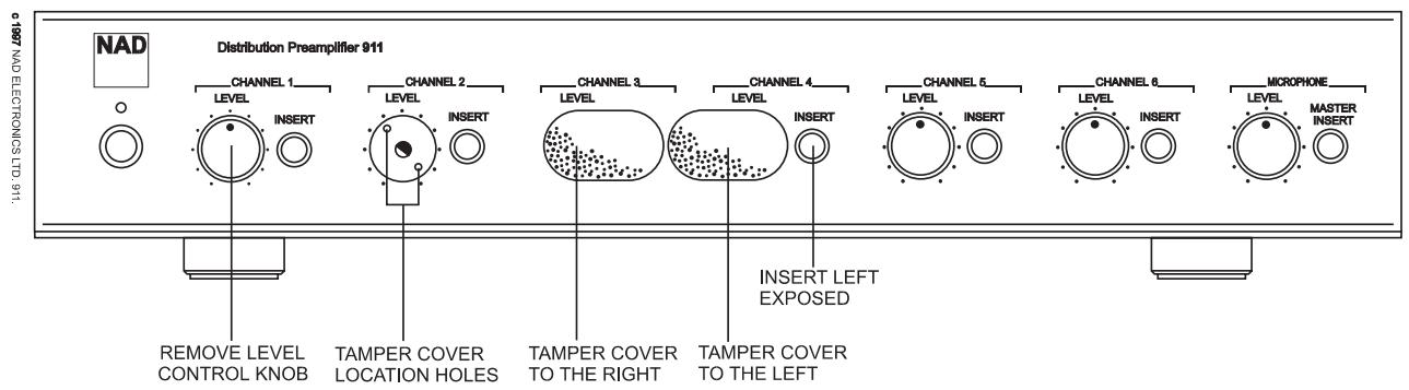
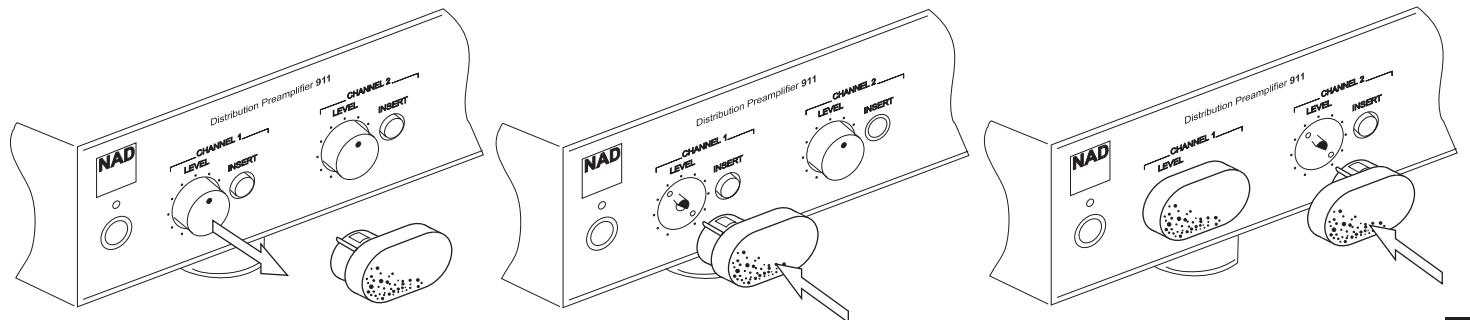
TAMPER-PROOF COVERS.
If the system is to be installed so that its level settings do not need to be changed in normal operation, then use the Tamper-proof Covers included with your NAD-911 to stop accidental use of the LEVEL controls and/or INSERT buttons. Fitting it with the Insert Button section of the cover to the right, will protect both the level settings and the insert button settings. Using the cover with the insert button section to the left leaves the insert button available.
Remove the volume control on any channels that need tamper-proofing, by gently pulling the LEVEL knob off its spindle.
flowchart
graph TD
    A["CD PLAYER"] --> B["PREAMPLIFIER"]
    B --> C["911 FROM MICROPHONE"]
    C --> D["911"]
    D --> E["911 LINKED TO NEXT 911 DISTRIBUTION PREAMPLIFIER"]
    E --> F["911"]
    F --> G["911"]
    G --> H["911"]
    H --> I["911"]
    I --> J["911"]
    J --> K["911"]
    K --> L["911"]
    L --> M["911"]
    M --> N["911"]
    N --> O["911"]
    O --> P["911"]
    P --> Q["911"]
    Q --> R["911"]
Gently push the Tamper-proof Cover in the opening left by the volume control knob. Ensure that the two small legs on the Tamper-proof cover line up with the two holes in the sub-facia behind the front panel.
SERVICING, INSTALLATION AND CONFIGURATION INSTRUCTIONS
CAUTION: These servicing and installation instructions are for use by qualified personnel only. To reduce the risk of electric shock do not perform any servicing other than that contained in the operation instructions unless you are qualified to do so. Refer all servicing to qualified service personnel.
CAUTION: Before removing the top cover disconnect the unit from the mains supply.
Altering jumpers inside the unit can change the way the insert and variable level functions work so that the NAD-911 can be configured to meet the messaging requirements of the system. This must be done by qualified personnel only.
WHY USE DIFFERENT INSERT SETTINGS?
Whilst the basic function of accurately setting the music levels to individual speakers is generally the same in all installations, the announcement requirements may vary enormously. The Insert configuration allows installers to match the operation of the NAD-911 exactly to the announcement needs of the user.
MICROPHONE LINE OUT LEVEL, FIXED OR VARIABLE.
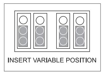
If the system is being used in an area where the music level needs to be varied as the background noise varies, then the announcement levels should also go up or down with the music level. This ensures that the announcements will be heard over the music and general background noise in the area. In this situation the insert function of each channel should be set to Insert Variable.
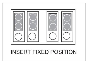
If the system is being used in an office or shop type of venue where the music level is only occasionally altered and set to low background level, then the Microphone level needs to be set up so that announcements can be heard clearly but are not too loud. Setting all channels to Insert Fixed helps to ensure that the correct announcement levels are maintained.
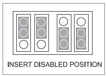
Some areas of the installation may never need announcements. Configure the channels feeding the speakers in these areas to Insert Disabled to ensure that announcements are not accidentally routed to these areas.
CONFIGURING THE NAD-911 INTERNAL JUMPERS.
With the unit unplugged from the AC socket, remove the lid by removing the 5 screws securing the top panel. When the 911 has been configured securely replace the unit's top panel.
FIXED OR VARIABLE MICROPHONE LINE OUT LEVEL.
In most installations using multiple NAD 911, it will be desirable to give the first 911 control over the microphone level for all 911s in the system. In this case the first 911 should be set to Variable and all following 911s should be set to Fixed. This way the second and subsequent 911s will not alter the Microphone Line out level to the next 911.
Change jumper JP25 from the factory default setting 'VARIABLE' to the 'FIXED' position.
CONFIGURING MICROPHONE AND MUSIC LEVELS.
Each channel can be configured individually so that the Microphone or Line Insert volume level will always be the same regardless of the individual channels level setting. Alternatively the channel can be configured so that the Microphone level is linked to the level of the music. Turning up the channel's level control will then also turn up the volume of the microphone.
A third setting switches off the microphone signal from that channel completely.
NOTE: For all channels the factory default is set to Variable.
FIXED MICROPHONE LEVEL.
To set up the channel so that the level of the Inserted signal (Microphone or pre-recorded message) to be at a preset level no matter what the individual channel volume setting is.
Set the four jumpers for that channel to INS FIXED.
LINKING MICROPHONE AND INPUT LEVELS.
To set up the channel so that the channel level control alters the volume of both the music and insert levels. Set the four Jumpers for that channel to INS VARIABLE.
DISABLING MICROPHONE INSERT ON A CHANNEL.
If you don't want the Insert signal to ever appear on a particular channel. Set the channel's first two jumpers (JP -01 and JP -02) to INS FIXED and set the second two jumpers (JP -03 and JP -04) to INS VARIABLE
CAUTION: Do not use any other configuration of the jumpers.

CHANNEL OPTIONS:
CONFIGURATION SETTINGS.
Use this table to keep a note of the NAD-911 set-
tings.
NAD 911 Ser. no:
Unit location......
Date......
Channel 1: Variable ____ Fixed ____ Disable ____
Channel 2: Variable ____ Fixed ____ Disable ____
Channel 3: Variable ____ Fixed ____ Disable ____
Channel 4: Variable ____ Fixed ____ Disable ____
Channel 5: Variable ____ Fixed ____ Disable ____
Channel 6: Variable ____ Fixed ____ Disable ____
Microphone Line Out: ____ Variable Fixed ____
TROUBLESHOOTING.
NO SOUND.
AC cord unplugged or power not switched on. Output lead not properly connected or damaged.
Amplifier not switched on, level controls too low or amplifier faulty. Speakers not properly connected or damaged Internal fuse blown
NO SOUND ONE CHANNEL.
Level controls set too low. Wrong channel being adjusted.
Microphone connected. Input leads not properly connected or damaged Source system not producing signal.
NO MICROPHONE SIGNAL OR FEEDBACK.
Microphone leads not properly connected or damaged Microphone not switched on. Microphone battery flat. Microphone requires ‘phantom’ powering.
Loud High Pitch sound when the Microphone is switched on.
Check AC socket, lead and fuse if fitted. Check the connections at both ends (NAD-911 and power amplifier). Check amplifier, connections and settings
Check connections and speakers. Consult dealer
Adjust level control. Check all channel level controls
Disconnect microphone Check connections. Check output of source system.
Check connections. Switch microphone on or to 'Talk' Check or replace microphone battery if used. Consult your microphone supplier for a suitable adapter. Feedback caused by the microphone being too close to a speaker. Move the speaker or microphone position or use the configuration jumpers to disable the Insert Feed to that particular speaker.
PREAMLIFICATEUR DE DISTRIBUTION NAD-911.
INFORMATIONS IMPORTANTES.
(Drawing: board layout with positions of J25, J101-104 etc.)
FESTEINGESTELLTE UND VARIABLE MICROPHONE LINE OUT EINSTELLUNG
| Measurement | Fixed outputLoad > 10K | Variable OutputLoad =600 | Line InsertIn | Mic in |
| Frequency response(20Hz-20KHz ref.1KHz) | -0.05dB | -0.05dB | -3dB @ 30Hz-0.8 @ 20KHz | -3dB @ 70Hz-0.2 @ 20KHz |
| Gain | 0.7dB | 16.5dB | 5.5dB | 50dB |
| S/N Ratio A-wtd. | 100dB | 87dB | 100dB | 65dB |
| THD+N | <0.003% | <0.01% | 0.004% | 1.2% |
| (2Vrms in 20Hz-20KHz 20dBu var. out) | ||||
| Intermodulation Distortion | <0.002% | <0.005% | 0.006% | 5% |
| Crosstalk (20Hz-20KHz) | <-88dB | <-72dB | <-72dB | |
| Input impedance | 47k +100 pF | 1.5k +1nF | 47k +100pF | |
| Maximum Output Level | >10Vrms | |||
| Maximum Input Voltage | >11Vrms | 12Vrms | 400mVrms | |
| Output Impedance | 1K | <0.1 | 1K | |
| Physical Specification | ||||
| Dimensions in mm (width x height x depth) | 435 x 85 x 306 | |||
| Net Weight | 4.3Kg | |||
| Shipping Weight | 5.6Kg | |||
NAD ELECTRONICS
(NEW ACOUSTIC DIMENSION)
LONDON
© 1997. 911 I.M. PRINTED IN TAIWAN R.O.C.
ISSUE 1 793030
- IMPORTANT SAFETY INSTRUCTIONS
- DO NOT ATTEMPT SERVICING OF THIS UNIT YOURSELF. REFER SERVICING TO QUALIFIED SERVICE PERSONNEL.
- ATTENTION
- CAUTION
- POWER LINES
- OUTDOOR ANTENNA GROUNDING
- INTRODUCTION TO THE NAD-911 DIS- TRIBUTION PREAMPLIFIER.
- IMPORTANT INFORMATION.
- CLEANING.
- REAR PANEL CONNECTIONS.
- 1.MIC IN
- 2.LINE INSERT IN
- 3.MIC LINE OUT
- INPUT (CHANNELS 1 -6)
- FIXED OUT (CHANNELS 1-6)
- 6.VARIABLE OUT (CHANNELS 1-6)
- POWER CABLE
- FRONT PANEL CONTROLS.
- POWER
- POWER LED
- CHANNELS 1 - 6.
- 3.LEVEL
- INSERT
- MICROPHONE.
- 5.LEVEL
- 6.MASTER INSERT
- PREAMPLIFIERS, AMPLIFIERS AND MIXERS FOR USE WITH THE NAD-911.
- CABLES.
- CONNECTING INPUTS.
- LINKING CHANNELS.
- BASIC CONNECTION AND OPERATION.
- CONNECTING OUTPUTS.
- SETTING THE MICROPHONE LEVEL.
- BASIC OPERATION.
- INSERT SIGNAL TO ALL CHANNELS
- INSERT SIGNAL ONLY ON SELECTED CHANNELS
- NOTE:
- USING MIC LINE OUT
- USING SEVERAL NAD-911s.
- TAMPER-PROOF COVERS.
- SERVICING, INSTALLATION AND CONFIGURATION INSTRUCTIONS
- WHY USE DIFFERENT INSERT SETTINGS?
- MICROPHONE LINE OUT LEVEL, FIXED OR VARIABLE.
- CONFIGURING THE NAD-911 INTERNAL JUMPERS.
- FIXED OR VARIABLE MICROPHONE LINE OUT LEVEL.
- CONFIGURING MICROPHONE AND MUSIC LEVELS.
- FIXED MICROPHONE LEVEL.
- LINKING MICROPHONE AND INPUT LEVELS.
- DISABLING MICROPHONE INSERT ON A CHANNEL.
- CHANNEL OPTIONS:
- CONFIGURATION SETTINGS.
- TROUBLESHOOTING.
- NO SOUND.
- NO SOUND ONE CHANNEL.
- NO MICROPHONE SIGNAL OR FEEDBACK.
- PREAMLIFICATEUR DE DISTRIBUTION NAD-911.
- INFORMATIONS IMPORTANTES.
- FESTEINGESTELLTE UND VARIABLE MICROPHONE LINE OUT EINSTELLUNG
Brand : NAD
Model : 911
Category : Audio Amplifier