
LS1018 - Miter saw MAKITA - Free user manual and instructions
Find the device manual for free LS1018 MAKITA in PDF.

| Product type | Radial miter saw |
| Brand | Makita |
| Model | LS1018 / LS1018L (with laser) |
| Blade diameter | 255 mm - 260 mm |
| Arbor diameter | 25.4 mm (outside Europe) / 30 mm (Europe) |
| No-load speed | 4 300 min⁻¹ |
| Dimensions (L × W × H) | 825 mm × 536 mm × 633 mm |
| Weight (EPTA 01/2003) | 19.8 kg (outside Europe) / 19.9 kg (Europe) |
| Power supply | Single-phase, voltage per nameplate, double insulation |
| Power | Not specified in manual (estimated ~ 1,400 W) |
| Max cutting capacity (H × D) at 0° miter and 0° bevel | 91 mm × 310 mm |
| Max cutting capacity at 45° miter and 0° bevel | 50 mm × 220 mm |
| Max cutting capacity at 45° bevel (left) and 0° miter | 91 mm × 220 mm |
| Max cutting capacity at 45° bevel and 45° miter | 50 mm × 220 mm |
| Miter angle range | 0° - 60° right, 0° - 45° left |
| Bevel angle range | 0° - 45° left and right |
| Special features | Soft start, laser guide (model L), double insulation, sliding cut |
| Laser (model LS1018L) | Red laser class 2, 650 nm, < 1 mW |
| Safety | Blade guard, safety button, shaft lock, possible padlock |
| Maintenance | Regular cleaning, lubrication of sliding parts, brush replacement |
| Spare parts / Repairability | Brushes, blade, flanges, rings, cutting table, dust bag |
| Included accessories | Socket/hex wrench, dust bag, vertical vise, right auxiliary guide, supports |
| Noise level | Sound pressure 97 dB(A), sound power 103 dB(A), uncertainty 3 dB(A) |
| Vibration | Emission < 2.5 m/s², uncertainty 1.5 m/s² |
Frequently Asked Questions - LS1018 MAKITA
User questions about LS1018 MAKITA
0 question about this device. Answer the ones you know or ask your own.
Ask a new question about this device
Download the instructions for your Miter saw in PDF format for free! Find your manual LS1018 - MAKITA and take your electronic device back in hand. On this page are published all the documents necessary for the use of your device. LS1018 by MAKITA.
USER MANUAL LS1018 MAKITA
natural_image
Technical line drawing of a mechanical cutting machine (no text or symbols)
natural_image
Technical line drawing of a mechanical assembly with no visible text or symbols1
2
3
natural_image
Technical line drawing of a mechanical device with labeled parts (no text or symbols present)4
5
6
7
8
9
10
11
12
13
14
natural_image
Technical line drawing of a mechanical assembly with no visible text or symbols15
16
17
18
19
natural_image
Technical line drawing of a mechanical assembly with no visible text or symbols20
21
22

natural_image
Technical line drawing of a mechanical assembly with no visible text or symbols23
24
25
26
27
28
29
30
31
32
33
34
35
36
37
38
39
natural_image
Technical line drawing of a mechanical device with a hand operating it, showing no text or symbols.40
41
42
flowchart
graph TD
    A["63"] --> B["1"]
    A --> C["2"]
    A --> D["3"]
    A --> E["4"]
    A --> F["64"]
    B --> G["1"]
    B --> H["2"]
    B --> I["3"]
    B --> J["4"]
    C --> K["1"]
    C --> L["2"]
    C --> M["3"]
    C --> N["4"]
    D --> O["1"]
    D --> P["2"]
    D --> Q["3"]
    D --> R["4"]
    E --> S["1"]
    E --> T["2"]
    E --> U["3"]
    E --> V["4"]
43
44
45

46
47
natural_image
Line drawing of a person operating a mechanical device (no text or symbols present)48
49
50
51
52
53
54
55
56
natural_image
Simple line drawing of a mechanical spring assembly with no text or symbols57
58
ENGLISH
Contents
SPECIFICATIONS....11
ADDITIONAL SAFETY RULES FOR TOOL....12
INSTALLATION 13
FUNCTIONAL DESCRIPTION 13
ASSEMBLY 15
OPERATION....17
MAINTENANCE....20
ACCESSORIES....21
FRANÇAIS
Table des matières
SPÉCIFICATIONS....22
CONSIGNES DE SÉCURITÉ ADDITIONNELLES
POUR L'OUTIL 23
INSTALLATION 24
DESCRIPTION DU FONCTIONNEMENT ...... 24
ASSEMBLAGE 27
FONCTIONNEMENT 29
ENTRETIEN 32
ACCESSOIRES 33
DEUTSCH
Inhalt
TECHNISCHE DATEN 35
ENGLISH (Original Instructions)
Explanation of general view
| 1. | Stopper pin | 28. | Switch trigger | 54. | Vise arm |
| 2. | Bolts | 29. | Hole for padlock | 55. | Vise knob |
| 3. | Blade guard | 30. | Switch for laser | 56. | Vise rod |
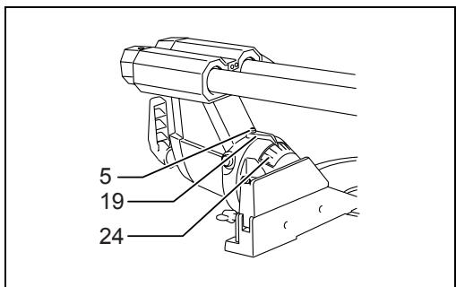
| 4. | Kerf board | 31. | Screw holding the laser unit box | 57. | Vise plate |
| 5. | Screw | 32. | Dry cell | 58. | Vise nut |
| 6. | Saw blade | 33. | Socket wrench with hex wrench on its other end | 59. | Holder |
| 7. | Blade teeth | 60. | 52/38° type crown molding | ||
| 8. | Left bevel cut | 34. | Wrench holder | 61. | 45° type crown molding |
| 9. | Straight cut | 35. | Socket wrench | 62. | 45° type cove molding |
| 10. | Right bevel cut | 36. | Blade case | 63. | Inside corner |
| 11. | Adjusting bolt | 37. | Center cover | 64. | Outside corner |
| 12. | Turn base | 38. | Hex bolt | 65. | Vise |
| 13. | Top surface of turn base | 39. | Arrow | 66. | Spacer block |
| 14. | Periphery of blade | 40. | Shaft lock | 67. | Aluminum extrusion |
| 15. | Guide fence | 41. | Hex bolt (left-handed) | 68. | Horizontal vise (optional accessory) |
| 16. | Stopper arm | 42. | Outer flange | ||
| 17. | Adjusting screw | 43. | Ring | 69. | Holes |
| 18. | Miter scale | 44. | Inner flange | 70. | Cut grooves with blade |
| 19. | Pointer | 45. | Spindle | 71. | Triangular rule |
| 20. | Lock lever | 46. | Dust nozzle | 72. | 0° adjusting bolt |
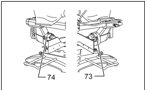
| 21. | Grip | 47. | Dust bag | 73. | Left 45° bevel angle adjusting bolt |
| 22. | Lever | 48. | Fastener | 74. | Right 45° bevel angle adjusting bolt |
| 23. | Arm | 49. | Support | ||
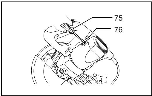
| 24. | Bevel scale | 50. | Sliding fence | 75. | Screwdriver |
| 25. | Release button | 51. | Clamping screw | 76. | Brush holder cap |
| 26. | Locking screw | 52. | Sub-fence R | ||
| 27. | Lock-off button | 53. | Screws |
SPECIFICATIONS
| Model | LS1018/LS1018L |
| Blade diameter | 255 mm - 260 mm |
| Hole diameter | |
| For all countries other than European countries | 25.4 mm |
| For European countries | 30 mm |
Max. Cutting capacities (H x W) with 260 mm in diameter
| Miter angle | Bevel angle | ||
| 45° (left) | 0° | 45° (right) | |
| 0° | 50 mm x 310 mm | 91 mm x 310 mm | 31 mm x 310 mm |
| 45° | 50 mm x 220 mm | 91 mm x 220 mm | 31 mm x 220 mm |
| 60° (right) | - | 91 mm x 153 mm | - |
No load speed (min ^-1 )
Laser Type (LS1018L only)
Dimensions (L x W x H)
Net weight
Safety class
- Due to our continuing programme of research and development, the specifications herein are subject to change without notice.
- Specifications may differ from country to country.
• Weight according to EPTA-Procedure 01/2003
Symbols
END222-1
The following show the symbols used for the equipment. Be sure that you understand their meaning before use.

..... Read instruction manual.

...... DOUBLE INSULATION

To avoid injury from flying debris, keep holding the saw head down, after making cuts, until the blade has come to a complete stop.
When performing slide cut, first pull carriage fully and press down handle, then push carriage toward the guide fence.

...... Do not place hand or fingers close to the blade.

Adjust sliding fences clear of blade and blade guard properly.

Always remove SUB-FENCE R when performing right bevel cuts. Failure to do so may cause serious injury to operator.

Never look into the laser beam. Direct laser beam may injure your eyes.
Intended use
ENE006-1
The tool is intended for accurate straight and miter cutting in wood. With appropriate saw blades, aluminum can also be sawed.
Power supply
ENF002-1
The tool should be connected only to a power supply of the same voltage as indicated on the nameplate, and can only be operated on single-phase AC supply. They are double-insulated in accordance with European Standard and can, therefore, also be used from sockets without earth wire.
General Power Tool Safety Warnings
GEA010-1
⚠ WARNING Read all safety warnings and all instructions. Failure to follow the warnings and instructions may result in electric shock, fire and/or serious injury.
Save all warnings and instructions for future reference.
ADDITIONAL SAFETY RULES FOR TOOL
ENB034-6
1. Wear eye protection.
-
Keep hands out of path of saw blade. Avoid contact with any coasting blade. It can still cause severe injury.
-
Do not operate saw without guards in place. Check blade guard for proper closing before each use. Do not operate saw if blade guard does not move freely and close instantly. Never clamp or tie the blade guard into the open position.
-
Do not perform any operation freehand. The workpiece must be secured firmly against the turn base and guide fence with the vise during all operations. Never use your hand to secure the workpiece.
-
Never reach around saw blade.
-
Turn off tool and wait for saw blade to stop before moving workpiece or changing settings.
-
Unplug tool before changing blade or servicing.
-
Always secure all moving portions before carrying the tool.
-
Stopper pin which locks the cutter head down is for carrying and storage purposes only and not for any cutting operations.
-
Do not use the tool in the presence of flammable liquids or gases. The electrical operation of the tool could create an explosion and fire when exposed to flammable liquids or gases.
-
Check the blade carefully for cracks or damage before operation. Replace cracked or damaged blade immediately.
-
Use only flanges specified for this tool.
-
Be careful not to damage the arbor, flanges (especially the installing surface) or bolt. Damage to these parts could result in blade breakage.
-
Make sure that the turn base is properly secured so it will not move during operation.
-
For your safety, remove the chips, small pieces, etc. from the table top before operation.
-
Avoid cutting nails. Inspect for and remove all nails from the workpiece before operation.
-
Make sure the shaft lock is released before the switch is turned on.
-
Be sure that the blade does not contact the turn base in the lowest position.
-
Hold the handle firmly. Be aware that the saw moves up or down slightly during start-up and stopping.
-
Make sure the blade is not contacting the workpiece before the switch is turned on.
-
Before using the tool on an actual workpiece, let it run for a while. Watch for vibration or wobbling that could indicate poor installation or a poorly balanced blade.
-
Wait until the blade attains full speed before cutting.
-
Stop operation immediately if you notice anything abnormal.
-
Do not attempt to lock the trigger in the on position.
-
Be alert at all times, especially during repetitive, monotonous operations. Do not be lulled into a false sense of security. Blades are extremely unforgiving.
-
Always use accessories recommended in this manual. Use of improper accessories such as abrasive wheels may cause an injury.
- Do not use the saw to cut other than wood, aluminum or similar materials.
- Connect miter saws to a dust collecting device when sawing.
- Select saw blades in relation to the material to be cut.
- Take care when slotting.
- Replace the kerf board when worn.
- Do not use saw blades manufactured from high speed steel.
- Some dust created from operation contains chemicals known to cause cancer, birth defects or other reproductive harm. Some examples of these chemicals are:
- lead from lead-based-painted material and,
• arsenic and chromium from chemically-treated lumber.
Your risk from these exposures varies, depending on how often you do this type of work. To reduce your exposure to these chemicals: work in a well ventilated area and work with approved safety equipment, such as those dust masks that are specially designed to filter out microscopic particles.
- To reduce the emitted noise, always be sure that the blade is sharp and clean.
- The operator is adequately trained in the use, adjustment and operation of the machine.
- Use correctly sharpened saw blades. Observe the maximum speed marked on the saw blade.
- Refrain from removing any cut-offs or other parts of the workpiece from the cutting area whilst the tool is running and the saw head is not in the rest position.
- Use only saw blades recommended by the manufacturer which conform to EN847-1.
- Wear gloves for handling saw blade (saw blades shall be carried in a holder wherever practicable) and rough material.
- When fitted with laser, no exchange with different type of laser is permitted. Repairs shall only be carried out correctly.
SAVE THESE INSTRUCTIONS.
INSTALLATION
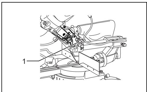
Bench mounting (Fig. 1)
When the tool is shipped, the handle is locked in the lowered position by the stopper pin. Release the stopper pin by simultaneously applying a slight downward pressure on the handle and pulling the stopper pin.
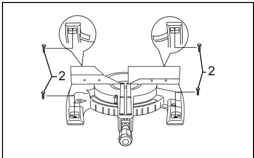
(Fig. 2)
This tool should be bolted with four bolts to a level and stable surface using the bolt holes provided in the tool's base. This will help prevent tipping and possible injury.
FUNCTIONAL DESCRIPTION
WARNING:
- Always be sure that the tool is switched off and unplugged before adjusting or checking function on the tool. Failure to switch off and unplug the tool may result in serious personal injury from accidental start-up.
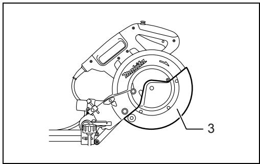
Blade guard (Fig. 3)
When lowering the handle, the blade guard rises automatically. The blade guard returns to its original position when the cut is completed and the handle is raised.
WARNING:
- Never defeat or remove the blade guard or the spring which attaches to the guard. An exposed blade as a result of defeated guarding may result in serious personal injury during operation.
In the interest of your personal safety, always maintain the blade guard in good condition. Any irregular operation of the blade guard should be corrected immediately. Check to assure spring loaded return action of guard.
WARNING:
- Never use the tool if the blade guard or spring are damaged, faulty or removed. Operation of the tool with a damaged, faulty or removed guard may result in serious personal injury.
If the see-through blade guard becomes dirty, or sawdust adheres to it in such a way that the blade and/or workpiece is no longer easily visible, unplug the saw and clean the guard carefully with a damp cloth. Do not use solvents or any petroleum-based cleaners on the plastic guard because this may cause damage to the guard.
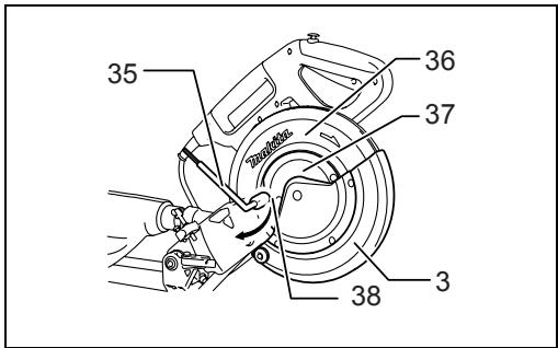
If the blade guard becomes dirty and needs to be cleaned for proper operation follow the steps below:
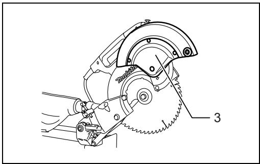
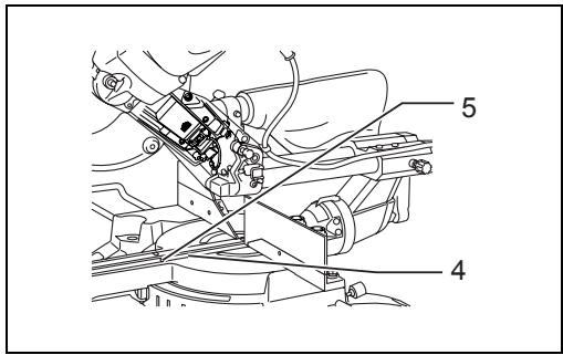
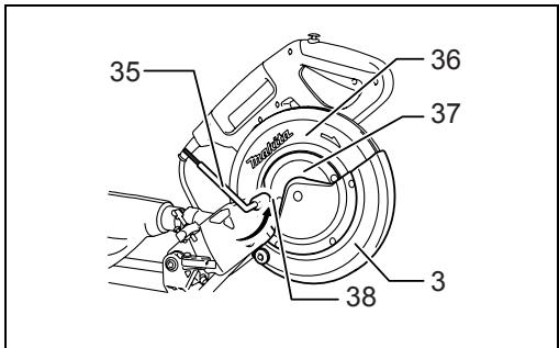
With the tool switched off and unplugged, use the supplied socket wrench to loosen the hex bolt holding the center cover. Loosen the hex bolt by turning it counterclockwise and raise the blade guard and center cover. (Fig. 4)
With the blade guard so positioned, cleaning can be more completely and efficiently accomplished. When cleaning is complete reverse procedure above and secure bolt. Do not remove spring holding blade guard. If guard becomes damaged through age or UV light exposure, contact a Makita service center for a new guard. DO NOT DEFEAT OR REMOVE GUARD.
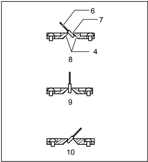
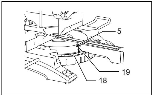
Positioning kerf board (Fig. 5 & 6)
This tool is provided with the kerf boards in the turn base to minimize tearing on the exit side of a cut. The kerf boards are factory adjusted so that the saw blade does not contact the kerf boards. Before use, adjust the kerf boards as follows:
First, unplug the tool. Loosen all the screws (3 each on left and right) securing the kerf boards. Re-tighten them only to the extent that the kerf boards can still be easily moved by hand. Lower the handle fully and push in the stopper pin to lock the handle in the lowered position. Loosen the screw which secures the slide poles. Pull the carriage toward you fully. Adjust the kerf boards so that the kerf
boards just contact the sides of the blade teeth. Tighten the front screws (do not tighten firmly). Push the carriage toward the guide fence fully and adjust the kerf boards so that the kerf boards just contact the sides of blade teeth. Tighten the rear screws (do not tighten firmly).
After adjusting the kerf boards, release the stopper pin and raise the handle. Then tighten all the screws securely.
NOTICE:
- After setting the bevel angle ensure that the kerf boards are adjusted properly. Correct adjustment of the kerf boards will help provide proper support of the workpiece minimizing workpiece tear out.
Maintaining maximum cutting capacity
This tool is factory adjusted to provide the maximum cutting capacity for a 255 mm saw blade.
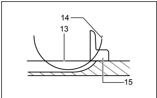
Unplug the tool before any adjustment is attempted. When installing a new blade, always check the lower limit position of the blade and if necessary, adjust it as follows: (Fig. 7 & 8)
First, unplug the tool. Push the carriage toward the guide fence fully and lower the handle completely. Use the hex. wrench to turn the adjusting bolt until the periphery of the blade extends slightly below the top surface of the turn base at the point where the front face of the guide fence meets the top surface of the turn base.
With the tool unplugged, rotate the blade by hand while holding the handle all the way down to be sure that the blade does not contact any part of the lower base. Re-adjust slightly, if necessary.

WARNING:
- After installing a new blade and with the tool unplugged, always be sure that the blade does not contact any part of the lower base when the handle is lowered completely. If a blade makes contact with the base it may cause kickback and result in serious personal injury.
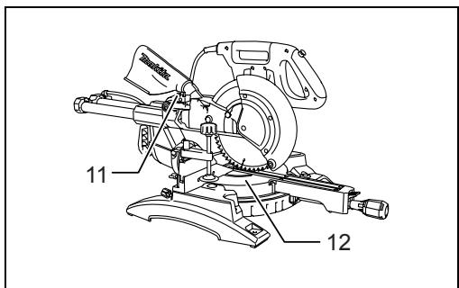
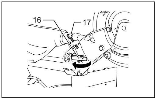
Stopper arm (Fig. 9)
The lower limit position of the blade can be easily adjusted with the stopper arm. To adjust it, move the stopper arm in the direction of the arrow as shown in the figure. Adjust the adjusting screw so that the blade stops at the desired position when lowering the handle fully.
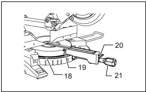
Adjusting the miter angle (Fig. 10)
Loosen the grip by turning counterclockwise. Turn the turn base while pressing down the lock lever. When you have moved the grip to the position where the pointer points to the desired angle on the miter scale, securely tighten the grip clockwise.

CAUTION:
- After changing the miter angle, always secure the turn base by tightening the grip firmly.
NOTICE:
- When turning the turn base, be sure to raise the handle fully.
Adjusting the bevel angle (Fig. 11)
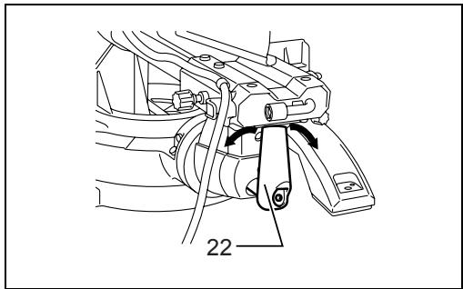
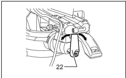
To adjust the bevel angle, loosen the lever at the rear of the tool counterclockwise. Unlock the arm by pushing the handle somewhat strongly in the direction that you intend to tilt the saw blade.
NOTE:
- Lever can be adjusted to a different lever angle by removing the screw holding the lever and securing the lever at a desired angle. (Fig. 12)
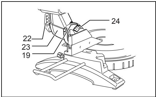
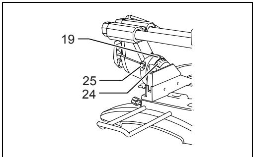
Tilt the saw blade until the pointer points to the desired angle on the bevel scale. Then tighten the lever clockwise firmly to secure the arm. (Fig. 13)
When tilting the carriage to the right, tilt the carriage to the left slightly after loosening the lever and press the releasing button. With the releasing button being pressed, tilt the carriage to the right. (Fig. 14)
Tilt the saw blade until the pointer points to the desired angle on the bevel scale. Then tighten the lever clockwise firmly to secure the arm.
- When changing bevel angles, be sure to position the kerf boards appropriately as explained in the "Positioning kerf boards" section.

CAUTION:
- After changing the bevel angle, always secure the arm by tightening the lever clockwise.
NOTICE:
- When tilting the saw blade be sure the handle is fully raised.
- When changing bevel angles, be sure to position the kerf boards appropriately as explained in the "Positioning kerf boards" section.
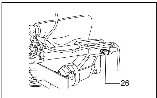
Slide lock adjustment (Fig. 15)
To lock the slide pole, turn the locking screw clockwise.
Switch action
For European countries (Fig. 16)
To prevent the switch trigger from being accidentally pulled, a lock-off button is provided. To start the tool, push the lever to the left, press in the lock-off button and then pull the switch trigger. Release the switch trigger to stop.

WARNING:
- Before plugging in the tool, always check to see that the switch trigger actuates properly and returns to the "OFF" position when released. Do not pull the switch trigger hard without pressing in the lock-off button. This can cause switch breakage. Operating a tool with a switch that does not actuate properly can lead to loss of control and serious personal injury.
A hole is provided in the switch trigger for insertion of padlock to lock the tool off.
For all countries other than European countries (Fig. 17)
To prevent the switch trigger from being accidentally pulled, a lock-off button is provided. To start the tool, press in the lock-off button and pull the switch trigger. Release the switch trigger to stop.

WARNING:
- Before plugging in the tool, always check to see that the switch trigger actuates properly and returns to the "OFF" position when released. Do not pull the switch trigger hard without pressing in
the lock-off button. This can cause switch
breakage. Operating a tool with a switch that does not actuate properly can lead to loss of control and serious personal injury.
A hole is provided in the switch trigger for insertion of padlock to lock the tool off.

WARNING:
- Do not use a lock with a shank or cable any smaller than 6.35 mm in diameter. A smaller shank or cable may not properly lock the tool in the off position and unintentional operation may occur resulting in serious personal injury.
- NEVER use tool without a fully operative switch trigger. Any tool with an inoperative switch is HIGHLY DANGEROUS and must be repaired before further usage or serious personal injury may occur.
- For your safety, this tool is equipped with a lock-off button which prevents the tool from unintended starting. NEVER use the tool if it runs when you simply pull the switch trigger without pressing the lock-off button. A switch in need of repair may result in unintentional operation and serious personal injury. Return tool to a Makita service center for proper repairs BEFORE further usage.
- NEVER defeat the lock-off button by taping down or some other means. A switch with a defeated lock-off button may result in unintentional operation and serious personal injury.
Electronic function
Soft start feature
- This function allows the smooth start-up of the tool by limiting the start-up torque.
Laser beam action
For model LS1018L only
NOTE:
- Before the first use, install the dry cells provided separately from the tool in the cell box. Refer to the section titled “Replacing the dry cells for laser unit” for the installment.

CAUTION:
- When not in use, be sure to turn off the laser. (Fig. 18)

CAUTION:
- Never look into the laser beam. Direct laser beam may injure your eyes.
- LASER RADIATION, DO NOT STARE INTO THE BEAM, CLASS 2 LASER PRODUCT.
- Before shifting the laser line or performing maintenance adjustment, be sure to unplug the tool.
To turn on the laser beam, press the upper position (I) of the switch. To turn off the laser beam, press the lower position (0) of the switch.
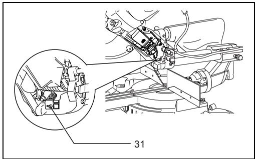
Laser line can be shifted to either the left or right side of the saw blade by loosening the screw holding the laser unit box and shifting it in the desired direction. After shifting, be sure to tighten the screw. (Fig. 19)
Laser line is factory adjusted so that it is positioned within 1 mm from the side surface of the blade (cutting position).
NOTE:
- When laser line appears dim and hard to see because of direct sunlight, relocate the work area to a place where there is less direct sunlight.
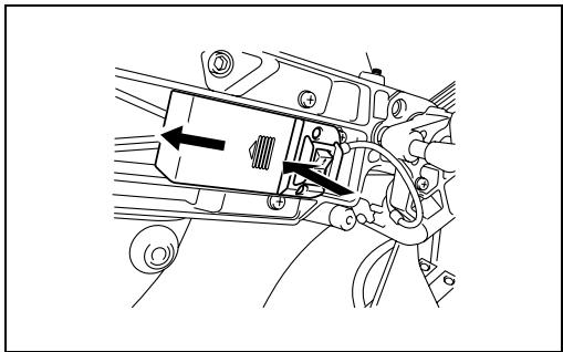
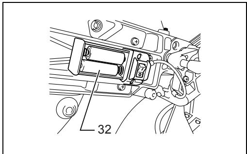
Replacing the dry cells for laser unit (Fig. 20 & 21)
Remove the lid for the dry cells for laser unit by sliding while pressing it. Take out the old dry cells and put the new ones as shown in the figure. After replacing, return the lid to cover it.
Cleaning of the lens for the laser light
If the lens for the laser light becomes dirty, or sawdust adheres to it in such a way that the laser line is no longer easily visible, unplug the saw and remove and clean the lens for the laser light carefully with a damp, soft cloth. Do not use solvents or any petroleum-based cleaners on the lens.
NOTE:
- When laser line is dim and almost or entirely invisible because of the direct sunlight in the indoor or outdoor window-by work, relocate the work area to a place not exposed to the direct sunlight.
ASSEMBLY

WARNING:
- Always be sure that the tool is switched off and unplugged before working on the tool. Failure to switch off and unplug the tool may result in serious personal injury.
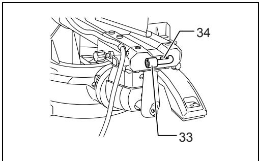
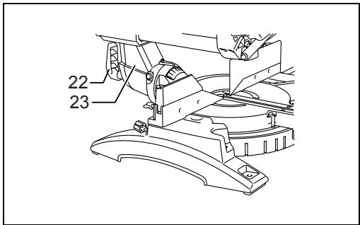
Storage of socket wrench with hex wrench on its other end (Fig. 22)
The socket wrench is stored as shown in the figure. When the socket wrench is needed it can be pulled out of the wrench holder.
After using the socket wrench it can be stored by returning it to the wrench holder.
Installing or removing saw blade

WARNING:
- Always be sure that the tool is switched off and unplugged before installing or removing the blade.
Accidental start up of the tool may result in serious personal injury. - Use only the Makita socket wrench provided to install or remove the blade. Failure to use the wrench may result in overtightening or insufficient tightening of the hex bolt and serious personal injury. (Fig. 23)
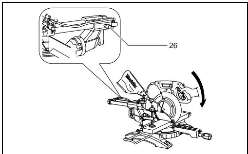
Lock the handle in the raised position by pushing in the stopper pin. (Fig. 24)
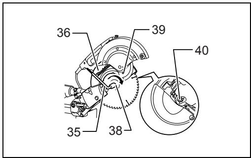
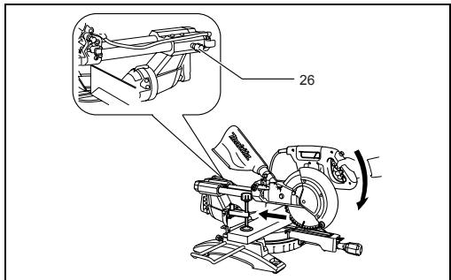
To remove the blade, use the socket wrench to loosen the hex bolt holding the center cover by turning it counterclockwise. Raise the blade guard and center cover. (Fig. 25)
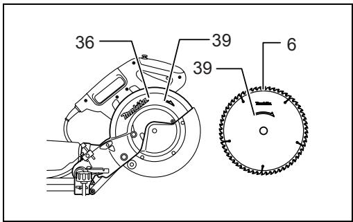
Press the shaft lock to lock the spindle and use the socket wrench to loosen the hex bolt clockwise. Then remove the hex bolt, outer flange and blade.
NOTE:
- If the inner flange is removed be sure to install it on the spindle with its protrusion facing away from the blade. If the flange is installed incorrectly the flange will rub against the machine.
WARNING:
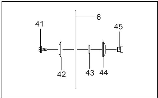
- Before mounting the blade onto the spindle, always be sure that the correct ring for the blade's arbor hole you intend to use is installed between the inner and the outer flanges. Use of the incorrect arbor hole ring may result in the improper mounting of the blade causing blade movement and severe vibration resulting in possible loss of control during operation and in serious personal injury. (Fig. 26)
To install the blade, mount it carefully onto the spindle, making sure that the direction of the arrow on the surface of the blade matches the direction of the arrow on the blade case.
Install the outer flange and hex bolt, and then use the socket wrench to tighten the hex bolt (left-handed) securely counterclockwise while pressing the shaft lock.
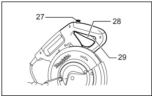
For all countries other than European countries (Fig. 27)
WARNING:
- The black ring 25 mm in outer diameter and the silver ring 25.4 mm in outer diameter are factory-installed as shown in the figure. When using a blade with 25 mm hole diameter, replace the silver ring with the black ring. Before mounting the blade onto the spindle, always be sure that the correct ring for the blade's arbor hole you intend to use is installed between the inner and the outer flanges. Use of the incorrect arbor hole ring may result in the improper mounting of the blade causing blade movement and severe vibration resulting in possible loss of control during operation and in serious personal injury.
For European countries
CAUTION:
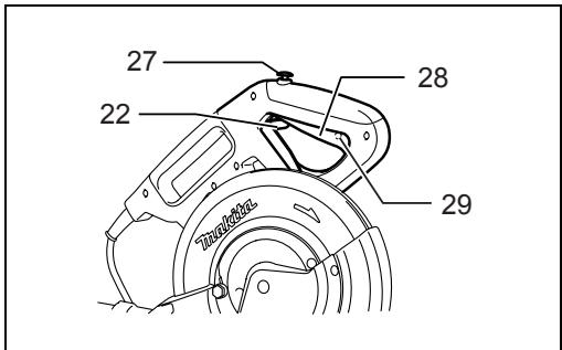
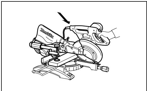
- The ring 30 mm in outer diameter is factory-installed between the inner and outer flanges. Install the outer flange and hex bolt, and then use the socket wrench to tighten the hex bolt securely counterclockwise while pressing the shaft lock. (Fig. 28) Return the blade guard and center cover to its original position. Then tighten the hex bolt clockwise to secure the center cover. Release the handle from the raised position by pulling the stopper pin. Lower the handle to make sure that the blade guard moves properly. Make sure the shaft lock has released spindle before making cut.
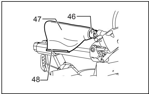
Dust bag (accessory) (Fig. 29)
The use of the dust bag makes cutting operations cleaner and dust collection easier. To attach the dust bag, fit it onto the dust nozzle.
When the dust bag is about half full, remove the dust bag from the tool and pull the fastener out. Empty the dust bag of its contents, tapping it lightly so as to remove particles adhering to the insides which might hamper further collection.
NOTE:
If you connect a vacuum cleaner to your saw, cleaner operations can be performed.
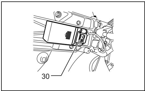
Securing workpiece
WARNING:
- It is extremely important to always secure the workpiece correctly with the proper type of vise or crown molding stoppers. Failure to do so may result in serious personal injury and cause damage to the tool and/or the workpiece.
- After a cutting operation do not raise the blade until it has come to a complete stop. The raising of a coasting blade may result in serious personal injury and damage to the workpiece.
- When cutting a workpiece that is longer than the support base of the saw, the material should be supported the entire length beyond the support base and at the same height to keep the material level. Proper workpiece support will help avoid blade pinch and possible kickback which may result in serious personal injury. Do not rely solely on the vertical vise and/or horizontal vise to secure the workpiece. Thin material tends to sag. Support workpiece over its entire length to avoid blade pinch and possible KICKBACK. (Fig. 30)
Guide fence (SLIDING FENCES which are upper and lower fences) adjustment (Fig. 31)
WARNING:
- Before operating the tool, make sure that the sliding fence is secured firmly.
- Before bevel-cutting, make sure that no part of the tool, especially the blade, contacts the upper and lower fences when fully lowering and raising the handle in any position and while moving the carriage through its full range of travel. If the tool or blade makes contact with the fence this may result in kickback or unexpected movement of the material and serious personal injury. (Fig. 32)
CAUTION:
- When performing bevel cuts, slide the sliding fence to the left and secure it as shown in the figure. Otherwise, it will contact the blade or a part of the tool, causing possible serious injury to the operator.
This tool is equipped with the sliding fence which should ordinarily be positioned as shown in the figure.
However, when performing left bevel cuts, set it to the left position as shown in the figure if the tool head contacts it. When bevel-cutting operations are complete, don't forget to return the sliding fence to the original position and secure it by firmly tightening the clamping screw.
Sub-fence R
WARNING:
- Before operating the tool, make sure that the sub-fence R is secured firmly.
- Before performing right bevel cuts, remove the sub-fence R. It will contact the blade or a part of the tool,
causing possible serious injury to the operator.
(Fig. 33)
The sub-fence R can be removed from the right side of the guide fence. To remove the sub-fence R, loosen the screw which secures the sub-fence R and pull it out. Follow the removal procedure in reverse to install it. When bevel-cutting operations are complete, don't forget to return the sub-fence R to the original position and secure it by firmly tightening the clamping screw.
Vertical vise (Fig. 34)
The vertical vise can be installed on either the left or right side of the guide fence. Insert the vise rod into the hole in the guide fence and tighten the screw on the back of the guide fence to secure the vise rod.
Position the vise arm according to the thickness and shape of the workpiece and secure the vise arm by tightening the screw. If the screw to secure the vise arm contacts the guide fence, install the screw on the opposite side of vise arm. Make sure that no part of the tool contacts the vise when lowering the handle fully and pulling or pushing the carriage all the way. If some part contacts the vise, re-position the vise.
Press the workpiece flat against the guide fence and the turn base. Position the workpiece at the desired cutting position and secure it firmly by tightening the vise knob.

WARNING:
- The workpiece must be secured firmly against the turn base and guide fence with the vise during all operations. If the workpiece is not properly secured against the fence the material may move during the cutting operation causing possible damage to the blade, causing the material to be thrown and loss of control resulting in serious personal injury.
Horizontal vise (optional accessory) (Fig. 35)
The horizontal vise can be installed in two positions on either the left or right side of the base. When performing 10^ or greater miter cuts, install the horizontal vise on the side opposite the direction in which the turn base is to be turned. (Fig. 36)
By flipping the vise nut counterclockwise, the vise is released, and rapidly moves in and out. To grip the workpiece, push the vise knob forward until the vise plate contacts the workpiece and flip the vise nut clockwise. Then turn the vise knob clockwise to secure the workpiece.
The maximum width of workpiece which can be secured by the horizontal vise is 215 mm.
When installing the horizontal vise on the right side of the base, also use the sub-fence R to secure the workpiece more firmly. Refer to the “Sub-fence R” section described on previously for installing the sub-fence R.

WARNING:
- Always rotate the vise nut clockwise until the workpiece is properly secured. If the workpiece is not properly secured the material may move during the cutting operation causing possible damage to the blade, causing the material to be thrown and loss of control resulting in serious personal injury.
- When cutting a thin workpiece, such as base boards, against the fence, always use the horizontal vise.
Holders (Fig. 37)
The holders can be installed on either side as a convenient means of holding workpieces horizontally. Slip fully the holder rods into the holes in the base. Then tighten the holders securely with the screws.

WARNING:
- Always support a long workpiece so it is level with the top surface of the turn base for an accurate cut and to prevent dangerous loss of tool control. Proper workpiece support will help avoid blade pinch and possible kickback which may result in serious personal injury.
OPERATION
NOTICE:
- Before use, be sure to release the handle from the lowered position by pulling the stopper pin.
- Do not apply excessive pressure on the handle when cutting. Too much force may result in overload of the motor and/or decreased cutting efficiency. Push down handle with only as much force as is necessary for smooth cutting and without significant decrease in blade speed.
- Gently press down the handle to perform the cut. If the handle is pressed down with force or if lateral force is applied, the blade will vibrate and leave a mark (saw mark) in the workpiece and the precision of the cut will be impaired.
- During a slide cut, gently push the carriage toward the guide fence without stopping. If the carriage movement is stopped during the cut, a mark will be left in the workpiece and the precision of the cut will be impaired.

WARNING:
- Make sure the blade is not contacting the workpiece, etc. before the switch is turned on. Turning the tool on with the blade in contact with the workpiece may result in kickback and serious personal injury.
- Press cutting (cutting small workpieces) (Fig. 38) Workpieces up to 91 mm high and 70 mm wide can be cut in the following manner. Push the carriage toward the guide fence fully and tighten the locking screw clockwise to secure the carriage. Secure the workpiece correctly with the proper type of vise. Switch on the tool without the blade making any contact and wait until the blade attains full speed before lowering. Then gently lower the handle to the fully lowered position to cut the workpiece. When the cut is completed, switch off the tool and WAIT UNTIL THE BLADE HAS COME TO A COMPLETE STOP before returning the blade to its fully elevated position.

WARNING:
- Firmly tighten the knob clockwise so that the carriage will not move during operation. Insufficient tightening of the knob may cause possible kickback which may result in serious personal injury.
2. Slide (push) cutting (cutting wide workpieces) (Fig. 39)
Loosen the locking screw counterclockwise so that the carriage can slide freely. Secure the workpiece with the proper type of vise. Pull the carriage toward you fully. Switch on the tool without the blade making any contact and wait until the blade attains full speed. Press the handle down and PUSH THE CARRIAGE TOWARD THE GUIDE FENCE AND THROUGH THE WORKPIECE. When the cut is completed, switch off the tool and WAIT UNTIL THE BLADE HAS COME TO A COMPLETE STOP before returning the blade to its fully elevated position.
WARNING:
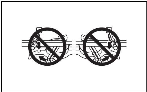
- Whenever performing a slide cut, first pull the carriage full towards you and press the handle all the way down, then push the carriage toward the guide fence. Never start the cut with the carriage not pulled fully toward you. If you perform the slide cut without the carriage pulled fully toward you unexpected kickback may occur and serious personal injury may result.
- Never attempt to perform a slide cut by pulling the carriage towards you. Pulling the carriage towards you while cutting may cause unexpected kickback resulting in possible serious personal injury.
- Never perform the slide cut with the handle locked in the lowered position.
- Never loosen the locking screw which secures the carriage while the blade is rotating. A loose carriage while cutting may cause unexpected kickback resulting in possible in serious personal injury.
3. Miter cutting
Refer to the previously covered “Adjusting the miter angle”.
4. Bevel cut (Fig. 40)
Loosen the lever and tilt the saw blade to set the bevel angle (Refer to the previously covered "Adjusting the bevel angle"). Be sure to retighten the lever firmly to secure the selected bevel angle safely. Secure the workpiece with a vise. Make sure the carriage is pulled all the way back toward the operator. Switch on the tool without the blade making any contact and wait until the blade attains full speed. Then gently lower the handle to the fully lowered position while applying pressure in parallel with the blade and PUSH THE CARRIAGE TOWARD THE GUIDE FENCE TO CUT THE WORKPIECE. When the cut is completed, switch off the tool and WAIT UNTIL THE BLADE HAS COME TO A COMPLETE STOP before returning the blade to its fully elevated position.
WARNING:
- After setting the blade for a bevel cut, before operating the tool ensure that the carriage and blade will have free travel throughout the entire range of the intended cut. Interruption of the carriage or blade travel during the cutting operation may result in kickback and serious personal injury.
- While making a bevel cut keep hands out of the path of the blade. The angle of the blade may confuse the operator as to the actual blade path while cutting
and contact with the blade will result in serious personal injury.
- The blade should not be raised until it has come to a complete stop. During a bevel cut the piece cut off may come to rest against the blade. If the blade is raised while it is rotating the cut-off piece maybe ejected by the blade causing the material to fragment which may result in serious personal injury.
NOTICE:
- When pressing down the handle, apply pressure in parallel with the blade. If a force is applied perpendicularly to the turn base or if the pressure direction is changed during a cut, the precision of the cut will be impaired.
- Before bevel-cutting, an adjustment of the upper fence and lower fence maybe required. Refer to the section titled "Guide fence adjustment".
CAUTION:
- Always remove the sub-fence R so that it does not interfere any part of the carriage when performing right bevel cuts.
5. Compound cutting
Compound cutting is the process in which a bevel angle is made at the same time in which a miter angle is being cut on a workpiece. Compound cutting can be performed at the angle shown in the table.
| Miter angle | Bevel angle |
| Left and Right 0° - 45° | Left and Right 0° - 45° |
When performing compound cutting, refer to “Press cutting”, “Slide cutting”, “Miter cutting” and “Bevel cut” explanations.
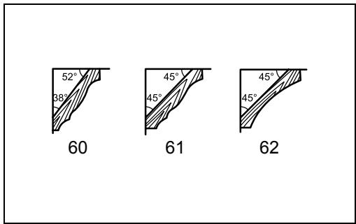
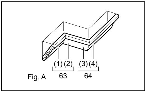
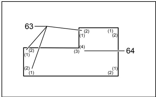
6. Cutting crown and cove moldings
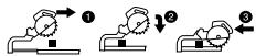
Crown and cove moldings can be cut on a compound miter saw with the moldings laid flat on the turn base. There are two common types of crown moldings and one type of cove moldings; 52/38° wall angle crown molding, 45° wall angle crown molding and 45° wall angle cove molding. See illustrations. (Fig. 41) There are crown and cove molding joints which are made to fit “Inside” 90° corners ((1) and (2) in Fig. A) and “Outside” 90° corners ((3) and (4) in Fig. A).
(Fig. 42 & 43)
Measuring
Measure the wall length and adjust workpiece on table to cut wall contact edge to desired length. Always make sure that cut workpiece length at the back of the workpiece is the same as wall length. Adjust cut length for angle of cut. Always use several pieces for test cuts to check the saw angles.
When cutting crown and cove moldings, set the bevel angle and miter angle as indicated in the table (A) and position the moldings on the top surface of the saw base as indicated in the table (B).
In the case of left bevel cut
Table (A)
| Molding position in Fig. A | Bevel angle | Miter angle | |||
| 52/38° type | 45° type | 52/38° type | 45° type | ||
| For inside corner | (1) | Left 33.9° | Left 30° | Right 31.6° | Right 35.3° |
| (2) | Left 31.6° | Left 35.3° | |||
| For outside corner | (3) | ||||
| (4) | Right 31.6° | Right 35.3° | |||
Table (B)
| Molding position in Fig. A | Molding edge against guide fence | Finished piece | |
| For inside corner | (1) | Ceiling contact edge should be against guide fence. | Finished piece will be on the Left side of blade. |
| (2) | Wall contact edge should be against guide fence. | ||
| For outside corner | (3) | Finished piece will be on the Right side of blade. | |
| (4) | Ceiling contact edge should be against guide fence. |
Example:
In the case of cutting 52/38° type crown molding for position (1) in Fig. A:
- Tilt and secure bevel angle setting to 33.9^ LEFT.
- Adjust and secure miter angle setting to 31.6° RIGHT.
- Lay crown molding with its broad back (hidden) surface down on the turn base with its CEILING CONTACT EDGE against the guide fence on the saw.
- The finished piece to be used will always be on the LEFT side of the blade after the cut has been made.
In the case of right bevel cut
Table (A)
| Molding position in Fig. A | Bevel angle | Miter angle | |||
| 52/38° type | 45° type | 52/38° type | 45° type | ||
| For inside corner | (1) | Right 33.9° | Right 30° | Right 31.6° | Right 35.3° |
| (2) | Left 31.6° | Left 35.3° | |||
| For outside corner | (3) | ||||
| (4) | Right 31.6° | Right 35.3° | |||
Table (B)
| Molding position in Fig. A | Molding edge against guide fence | Finished piece | |
| For inside corner | (1) | Wall contact edge should be against guide fence. | Finished piece will be on the Right side of blade. |
| (2) | Ceiling contact edge should be against guide fence. | ||
| For outside corner | (3) | Finished piece will be on the Left side of blade. | |
| (4) | Wall contact edge should be against guide fence. |
Example:
In the case of cutting 52/38° type crown molding for position (1) in Fig. A:
- Tilt and secure bevel angle setting to 33.9^ RIGHT.
- Adjust and secure miter angle setting to 31.6° RIGHT.
- Lay crown molding with its broad back (hidden) surface down on the turn base with its WALL
CONTACT EDGE against the guide fence on the saw.
- The finished piece to be used will always be on the RIGHT side of the blade after the cut has been made.
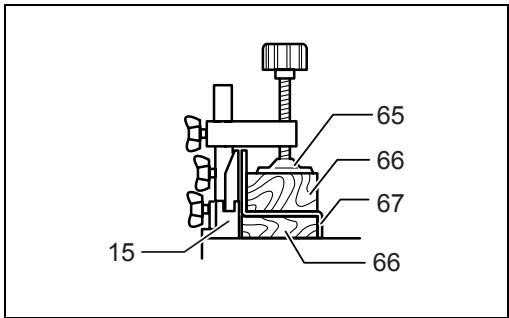
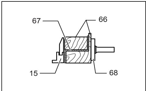
7. Cutting aluminum extrusion (Fig. 44 & 45)
When securing aluminum extrusions, use spacer blocks or pieces of scrap as shown in the figure to prevent deformation of the aluminum. Use a cutting lubricant when cutting the aluminum extrusion to prevent build-up of the aluminum material on the blade.
WARNING:
- Never attempt to cut thick or round aluminum extrusions. Thick or round aluminum extrusions can be difficult to secure and may work loose during the cutting operation which may result in loss of control and serious personal injury.
8. Wood facing
Use of wood facing helps to assure splinter-free cuts in workpieces. Attach a wood facing to the guide fence using the holes in the guide fence. See the figure concerning the dimensions for a suggested wood facing. (Fig. 46)
CAUTION:
- Use straight wood of even thickness as the wood facing.
WARNING:
- Use screws to attach the wood facing to the guide fence. The screws should be installed so that the screw heads are below the surface of the wood facing so that they will not interfere with the positioning of the material being cut. Misalignment of the material being cut can case unexpected movement during the cutting operation which may result in a loss of control and serious personal injury.
NOTICE:
- When the wood facing is attached, do not turn the turn base with the handle lowered. The blade and/or the wood facing will be damaged.
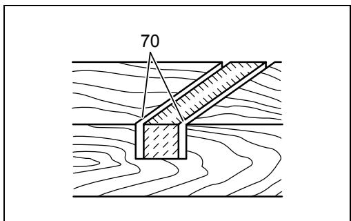
9. Groove cutting (Fig. 47)
A dado type cut can be made by proceeding as follows:
Adjust the lower limit position of the blade using the adjusting screw and the stopper arm to limit the cutting depth of the blade. Refer to “Stopper arm” section described previously.
After adjusting the lower limit position of the blade, cut parallel grooves across the width of the workpiece using a slide (push) cut as shown in the figure. Then remove the workpiece material between the grooves with a chisel.
WARNING:
- Do not attempt to perform this type of cut by using a wider type blade or dado blade. Attempting to make a groove cut with a wider blade or dado blade could lead to unexpected cutting results and kickback which may result in serious personal injury.
- Be sure to return the stopper arm to the original position when performing other than groove cutting. Attempting to make cuts with the stopper arm in the incorrect position could lead to unexpected cutting results and kickback which may result in serious personal injury.
CAUTION:
- Be sure to return the stopper arm to the original position when performing other than groove cutting.
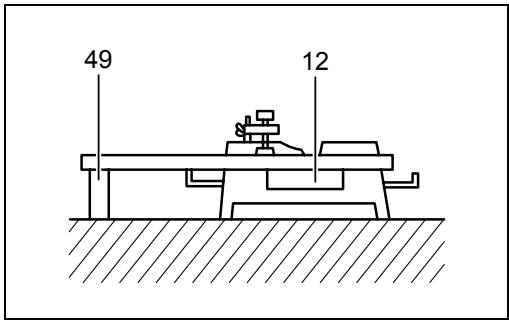
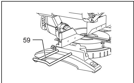
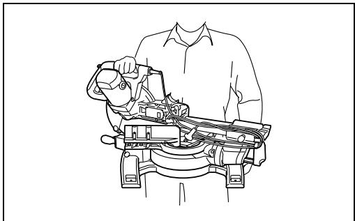
Carrying tool (Fig. 48)
Make sure that the tool is unplugged. Secure the blade at 0^ bevel angle and the turn base at the full right miter angle position. Secure the slide poles so that the lower slide pole is locked in the position of the carriage fully pulled to operator and the upper poles are locked in the position of the carriage fully pushed forward to the guide fence (refer to the section titled “Slide lock adjustment”.) Lower the handle fully and lock it in the lowered position by pushing in the stopper pin.
Wind the power supply cord using the cord rests.
WARNING:
- Stopper pin is only for carrying and storage purposes and should never be used for any cutting operations. The use of the stopper pin for cutting operations may cause unexpected movement of the saw blade resulting in kickback and serious personal injury.
Carry the tool by holding both sides of the tool base as shown in the figure. If you remove the holders, dust bag, etc., you can carry the tool more easily.
CAUTION:
- Always secure all moving portions before carrying the tool. If portions of the tool move or slide while being carried loss of control or balance may occur resulting in personal injury.
MAINTENANCE
WARNING:
- Always be sure that the tool is switched off and unplugged before attempting to perform inspection or maintenance. Failure to unplug and switch off the tool may result in accidental start up of the tool which may result in serious personal injury.
- Always be sure that the blade is sharp and clean for the best and safest performance. Attempting a cut with a dull and /or dirty blade may cause kickback and result in a serious personal injury.
NOTICE:
- Never use gasoline, benzine, thinner, alcohol or the like. Discoloration, deformation or cracks may result.
Adjusting the cutting angle
This tool is carefully adjusted and aligned at the factory, but rough handling may have affected the alignment. If your tool is not aligned properly, perform the following:
1. Miter angle (Fig. 49)
Push the carriage toward the guide fence and tighten the locking screw to secure the carriage.
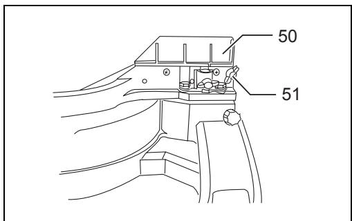
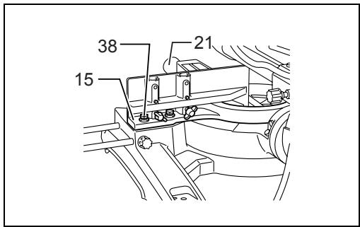
Loosen the grip which secures the turn base. Turn the turn base so that the pointer points to 0^ on the miter scale. Then turn the turn base slightly clockwise and counterclockwise to seat the turn base in the 0^ miter notch. (Leave as it is if the pointer does not point to 0^ .) Loosen the hex sockets bolts securing the guide fence using the socket wrench. (Fig. 50)
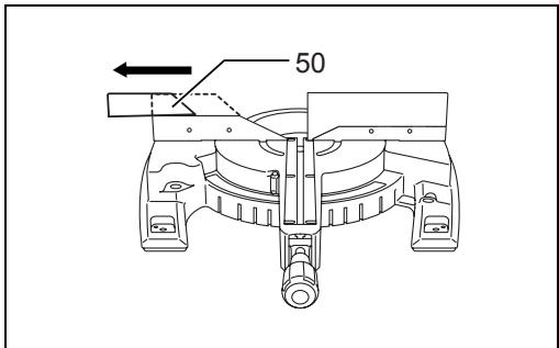
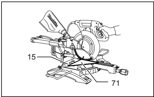
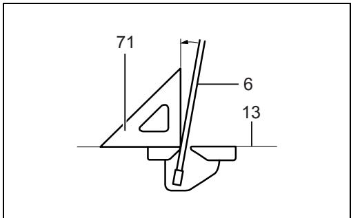
Lower the handle fully and lock it in the lowered position by pushing in the stopper pin. Square the side of the blade with the face of the guide fence using a triangular rule, try-square, etc. Then securely tighten the hex socket bolts on the guide fence in order starting from the right side. (Fig. 51)
Make sure that the pointer points to 0^ on the miter scale. If the pointer does not point to 0^ , loosen the screw which secures the pointer and adjust the pointer so that it will point to 0^ .
2. Bevel angle
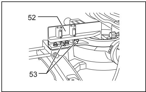
(1) 0° bevel angle (Fig. 52)
Push the carriage toward the guide fence and tighten the locking screw to secure the carriage. Lower the handle fully and lock it in the lowered position by pushing in the stopper pin. Loosen the lever at the rear of the tool. (Fig. 53)
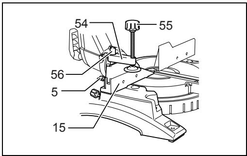
Turn the hex bolt on the right side of the arm two or three revolutions counterclockwise to tilt the blade to the right. (Fig. 54)
Carefully square the side of the blade with the top surface of the turn base using the triangular rule, try-square, etc. by turning the hex bolt on the right side of the arm clockwise. Then tighten the lever securely. (Fig. 55)
Make sure that the pointer on the arm point to 0^ on the bevel scale on the arm holder. If they do not point to 0^ , loosen the screw which secure the pointer and adjust it so that it will point to 0^ .
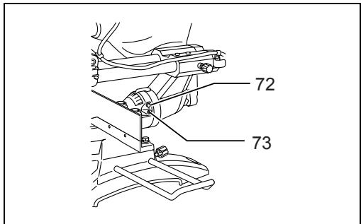
(2) 45^ bevel angle (Fig. 56)
Adjust the 45^ bevel angle only after performing 0^ bevel angle adjustment. To adjust left 45^ bevel angle, loosen the lever and tilt the blade to the left fully. Make sure that the pointer on the arm points to 45^ on the bevel scale on the arm holder. If the pointer does not point to 45^ , turn the 45^ bevel angle adjusting bolt on the right side of the arm holder until the pointer points to 45^ .
To adjust the right 45^ bevel angle, perform the same procedure as that described above.
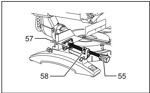
(Fig. 57)
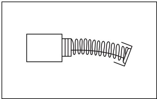
Remove and check the carbon brushes regularly. Replace when they wear down to 3 mm in length. Keep the carbon brushes clean and free to slip in the holders. Both carbon brushes should be replaced at the same time. Use only identical carbon brushes. (Fig. 58)
Use a screwdriver to remove the brush holder caps. Take out the worn carbon brushes, insert the new ones and secure the brush holder caps.
After use
- After use, wipe off chips and dust adhering to the tool with a cloth or the like. Keep the blade guard clean according to the directions in the previously covered section titled "Blade guard". Lubricate the sliding portions with machine oil to prevent rust.
- When storing the tool, pull the carriage toward you fully.
To maintain product SAFETY and RELIABILITY, repairs, any other maintenance or adjustment should be performed by Makita Authorized Service Centers, always using Makita replacement parts.
ACCESSORIES

WARNING:
- These Makita accessories or attachments are recommended for use with your Makita tool specified in this manual. The use of any other accessories or attachments may result in serious personal injury.
- Only use the Makita accessory or attachment for its stated purpose. Misuse of an accessory or attachment may result in serious personal injury. If you need any assistance for more details regarding these accessories, ask your local Makita Service Center.
• Steel & Carbide-tipped saw blades
| Miter saw blades | For smooth and precise cutting in various materials. |
| Combination | General purpose blade for fast and smooth rip, crosscuts and miters. |
| Crosscutting | For smoother cross grain cuts. Slices cleanly against the grain. |
| Fine cross cuts | For sand-free cuts cleanly against the grain. |
| Non-ferrous metals miter saw blades | For miters in aluminum, copper, brass, tubing, and other non-ferrous metals. |
- Sub-fence R
• Vise assembly (Horizontal vise) - Vertical vise
- Socket wrench with hex wrench on its other end
- Holder
- Dust bag
- Elbow
- Triangular rule
Noise
ENG905-1
The typical A-weighted noise level determined according to EN61029:
Sound pressure level ( L_pA ): 97 dB (A)
Sound power level (LWA): 103 dB (A)
Uncertainty (K): 3 dB (A)
Wear ear protection.
Vibration
ENG900-1
The vibration total value (tri-axial vector sum) determined according to EN61029:
Vibration emission ( a_h ): 2.5 m/s ^2 or less
Uncertainty (K): 1.5 m/s²
ENG901-1
- The declared vibration emission value has been measured in accordance with the standard test method and may be used for comparing one tool with another.
- The declared vibration emission value may also be used in a preliminary assessment of exposure.

WARNING:
- The vibration emission during actual use of the power tool can differ from the declared emission value depending on the ways in which the tool is used.
- Be sure to identify safety measures to protect the operator that are based on an estimation of exposure in the actual conditions of use (taking account of all parts of the operating cycle such as the times when the tool is switched off and when it is running idle in addition to the trigger time).
For European countries only
ENG015-2
Noise and Vibration
The typical A-weighted noise levels are
sound pressure level: 97 dB (A)
sound power level: 103 dB (A)
Uncertainty: 3 dB (A)
Wear ear protection.
The typical weighted root mean square acceleration value is not more than 2.5 m/s^2 .
Uncertainty (K): 1.5 m/s²
These values have been obtained according to EN61029.
For European countries only
ENH003-12
EC Declaration of Conformity
We Makita Corporation as the responsible manufacturer declare that the following Makita machine(s):
Designation of Machine:
Slide Compound Miter Saw
Model No./ Type: LS1018, LS1018L
are of series production and
Conforms to the following European Directives:
2006/42/EC
And are manufactured in accordance with the following standards or standardised documents:
EN61029
The technical documentation is kept by our authorised representative in Europe who is:
Makita International Europe Ltd.,
Michigan Drive, Tongwell,
Milton Keynes, MK15 8JD, England
-
- 2009

Tomoyasu Kato
Director
Makita Corporation
3-11-8, Sumiyoshi-cho,
Anjo, Aichi, JAPAN
Dimensions (L x P x H)
Poids net
Niveau de sécurité
Michigan Drive, Tongwell,
Milton Keynes, MK15 8JD, Angleterre
-
- 2009

Tomoyasu Kato
Directeur
Makita Corporation
3-11-8, Sumiyoshi-cho,
Anjo, Aichi, JAPAN
Michigan Drive, Tongwell,
Milton Keynes, MK15 8JD, England
-
- 2009

Tomoyasu Kato
Direktor
Makita Corporation
3-11-8, Sumiyoshi-cho,
Anjo, Aichi, JAPAN
Michigan Drive, Tongwell,
Milton Keynes, MK15 8JD, Inghilterra
-
- 2009

Tomoyasu Kato
Direttore
Makita Corporation
3-11-8, Sumiyoshi-cho,
Anjo, Aichi, JAPAN
WAARSCHUWING Lees alle
Michigan Drive, Tongwell,
Milton Keynes, MK15 8JD, Engeland
-
- 2009

Tomoyasu Kato
Directeur
Makita Corporation
3-11-8, Sumiyoshi-cho,
Anjo, Aichi, JAPAN
Michigan Drive, Tongwell,
Milton Keynes, MK15 8JD, Inglaterra
-
- 2009

Tomoyasu Kato
Director
Makita Corporation
3-11-8, Sumiyoshi-cho,
Anjo, Aichi, JAPAN
Michigan Drive, Tongwell,
Milton Keynes, MK15 8JD, Inglaterra
-
- 2009

Tomoyasu Kato
Director
Makita Corporation
3-11-8, Sumiyoshi-cho,
Anjo, Aichi, JAPAN
3-11-8, Sumiyoshi-cho,
Anjo, Aichi, JAPAN
Michigan Drive, Tongwell,
Milton Keynes, MK15 8JD, England
-
- 2009

Tomoyasu Kato
Διευθυντής
Makita Corporation
3-11-8, Sumiyoshi-cho,
Anjo, Aichi, JAPAN
Makita Corporation
Anjo, Aichi, Japan
JM2328A026
www.makita.com

- ENGLISH
- Contents
- FRANÇAIS
- Table des matières
- DEUTSCH
- Inhalt
- Safety class
- Symbols
- Intended use
- Power supply
- General Power Tool Safety Warnings
- Save all warnings and instructions for future reference.
- ADDITIONAL SAFETY RULES FOR TOOL
- Wear eye protection.
- SAVE THESE INSTRUCTIONS.
- INSTALLATION
- Bench mounting (Fig. 1)
- (Fig. 2)
- FUNCTIONAL DESCRIPTION
- WARNING:
- Blade guard (Fig. 3)
- Positioning kerf board (Fig. 5 & 6)
- NOTICE:
- Maintaining maximum cutting capacity
- Stopper arm (Fig. 9)
- Adjusting the miter angle (Fig. 10)
- CAUTION:
- Adjusting the bevel angle (Fig. 11)
- NOTE:
- Slide lock adjustment (Fig. 15)
- Switch action
- For European countries (Fig. 16)
- For all countries other than European countries (Fig. 17)
- the lock-off button. This can cause switch
- Electronic function
- Soft start feature
- Laser beam action
- For model LS1018L only
- Replacing the dry cells for laser unit (Fig. 20 & 21)
- Cleaning of the lens for the laser light
- ASSEMBLY
- Storage of socket wrench with hex wrench on its other end (Fig. 22)
- Installing or removing saw blade
- For all countries other than European countries (Fig. 27)
- For European countries
- Dust bag (accessory) (Fig. 29)
- Securing workpiece
- Guide fence (SLIDING FENCES which are upper and lower fences) adjustment (Fig. 31)
- Sub-fence R
- (Fig. 33)
- Vertical vise (Fig. 34)
- Horizontal vise (optional accessory) (Fig. 35)
- Holders (Fig. 37)
- OPERATION
- Slide (push) cutting (cutting wide workpieces) (Fig. 39)
- Miter cutting
- Bevel cut (Fig. 40)
- Compound cutting
- Cutting crown and cove moldings
- (Fig. 42 & 43)
- Measuring
- In the case of left bevel cut
- Example:
- In the case of right bevel cut
- Cutting aluminum extrusion (Fig. 44 & 45)
- Wood facing
- Groove cutting (Fig. 47)
- Carrying tool (Fig. 48)
- MAINTENANCE
- Adjusting the cutting angle
- Miter angle (Fig. 49)
- Bevel angle
- (Fig. 57)
- After use
- ACCESSORIES
- Noise
- Wear ear protection.
- Vibration
- For European countries only
- Noise and Vibration
- EC Declaration of Conformity
- Conforms to the following European Directives:
- Tomoyasu Kato
- Niveau de sécurité
- WAARSCHUWING Lees alle
- Directeur
Brand : MAKITA
Model : LS1018
Category : Miter saw