
PowerEdge C6300 - Server DELL - Free user manual and instructions
Find the device manual for free PowerEdge C6300 DELL in PDF.


| Product Type | Blade Server Chassis |
| Model | PowerEdge C6300 |
| Brand | Dell |
| Form Factor | 4U Rack |
| Dimensions (H x W x D) | 6.9 x 17.6 x 30.0 inches (176 x 447 x 762 mm) |
| Weight (Empty) | 35 lbs (15.9 kg) |
| Weight (Fully Loaded) | 80 lbs (36.3 kg) |
| Power Supply | Dual redundant, 2400W each |
| Maximum Nodes | 4 half-height blade servers |
| Management Controller | Dell iDRAC with Lifecycle Controller |
| Cooling | Hot-swappable, redundant fans |
| Supported Node Types | PowerEdge C6320, C6320p, C6420 |
| Maintenance Features | Hot-swap blades, fans, power supplies; tool-less access |
| Security | TPM 2.0, Secure Boot, chassis intrusion detection |
| Spare Parts | Blade servers, mezzanine cards, fan modules, PSUs, midplane |
| Repairability | Modular design with field-replaceable units (FRUs) |
| Supported Operating Systems | Windows Server, Red Hat Enterprise Linux, SUSE Linux, VMware ESXi |
| Power Connector | IEC C20 (20A) per PSU |
| Operating Temperature | 10°C to 35°C (50°F to 95°F) |
Frequently Asked Questions - PowerEdge C6300 DELL
User questions about PowerEdge C6300 DELL
0 question about this device. Answer the ones you know or ask your own.
Ask a new question about this device
Download the instructions for your Server in PDF format for free! Find your manual PowerEdge C6300 - DELL and take your electronic device back in hand. On this page are published all the documents necessary for the use of your device. PowerEdge C6300 by DELL.
USER MANUAL PowerEdge C6300 DELL
Scan to see how-to videos, documentation, and troubleshooting information.

Quick Resource Locator
dell.com/QRL/Server/PEC6320
Dell PowerEdge
C6320
Getting Started
With Your System
Notes, Cautions, and Warnings

NOTE: A NOTE indicates important information that helps you make better use of your computer.

CAUTION: A CAUTION indicates potential damage to hardware or loss of data if instructions are not followed.

WARNING: A WARNING indicates a potential for property damage, personal injury, or death.
Copyright © 2015 Dell Inc. All rights reserved. This product is protected by U.S. and international copyright and intellectual property laws. Dell™ and the Dell logo are trademarks of Dell Inc. in the United States and/or other jurisdictions. All other marks and names mentioned herein may be trademarks of their respective companies.
Regulatory Model: B08S
Regulatory Type: B08S003

CAUTION: Restricted Access Location
This server is intended for installation only in restricted access locations as defined in Cl. 1.2.7.3 of IEC 60950-1: 2001 where both these conditions apply:
- Access can only be gained by service persons or by users who have been instructed about the reasons for the restrictions applied to the location and about any precautions that shall be taken.
- Access is through the use of a tool or lock and key, or other means of security, and is controlled by the authority responsible for the location.
Installation and Configuration

WARNING: Before performing the following procedure, review and follow the safety instructions that came with the system.
Installing the Tool-Less Rail Solution

WARNING: Whenever you need to lift the system, get others to assist you. To avoid injury, do not attempt to lift the system by yourself.

WARNING: The system is not fixed to the rack or mounted on the rails. To avoid personal injury or damage to the system, you must adequately support the system during installation and removal.

WARNING: To avoid a potential electrical shock hazard, a third wire safety grounding conductor is necessary for the rack installation. The rack equipment must provide sufficient airflow to the system to maintain proper cooling.

CAUTION: When installing rails in a square-hole rack it is important to ensure that the square peg slides through the square holes.
1 Push the latch release buttons on the midpoints of the end piece to open the rail latches. See Figure 1.
2 Align the end pieces of the rails on the vertical rack flanges to seat the pegs in the bottom hole of the first U and the top hole of the second U.

NOTE: The rails can be used in both square-hole (item 1 in the following figure) and round-hole racks (item 2 in the following figure).
Figure 1. Pushing the Latch Release Buttons
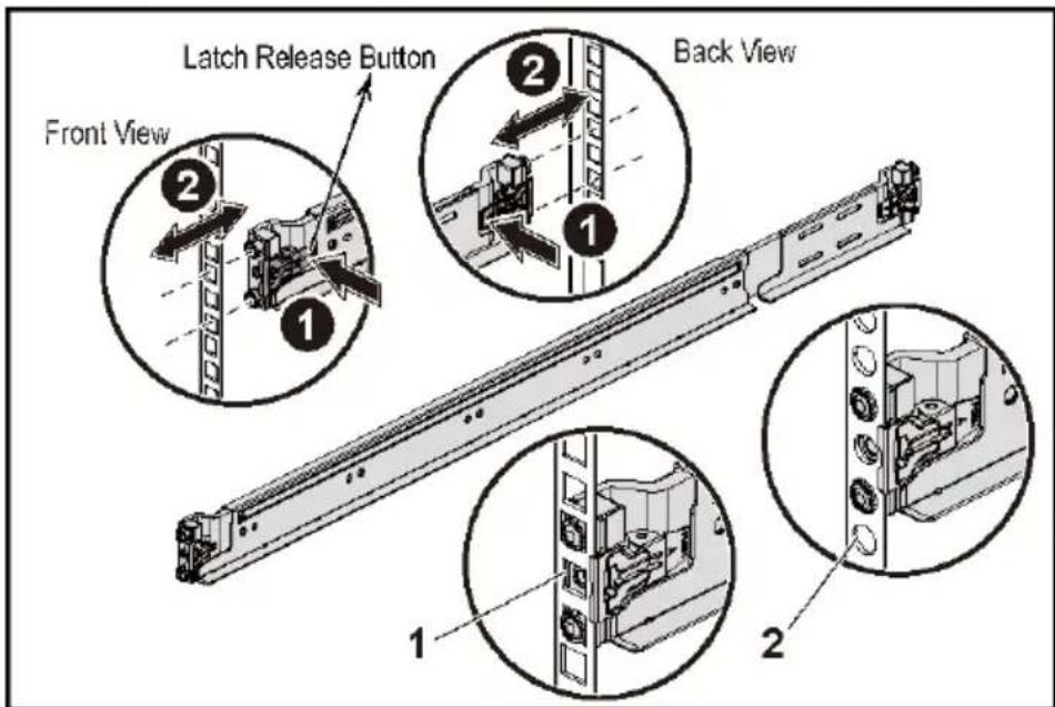

NOTE: To remove the rails, push the latch release button on the midpoints of the end piece and unseat each rail.
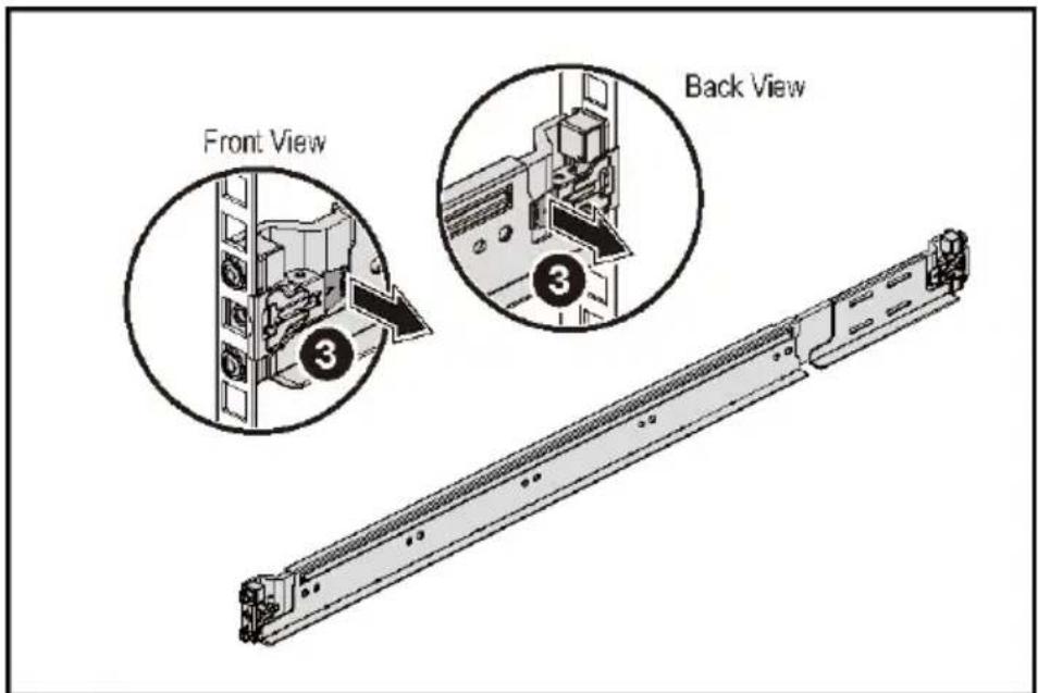
3 Engage the end of the rails and release the latch release button to have the latches locked in place. See Figure 2.
Figure 2. Releasing the Latch Release Buttons
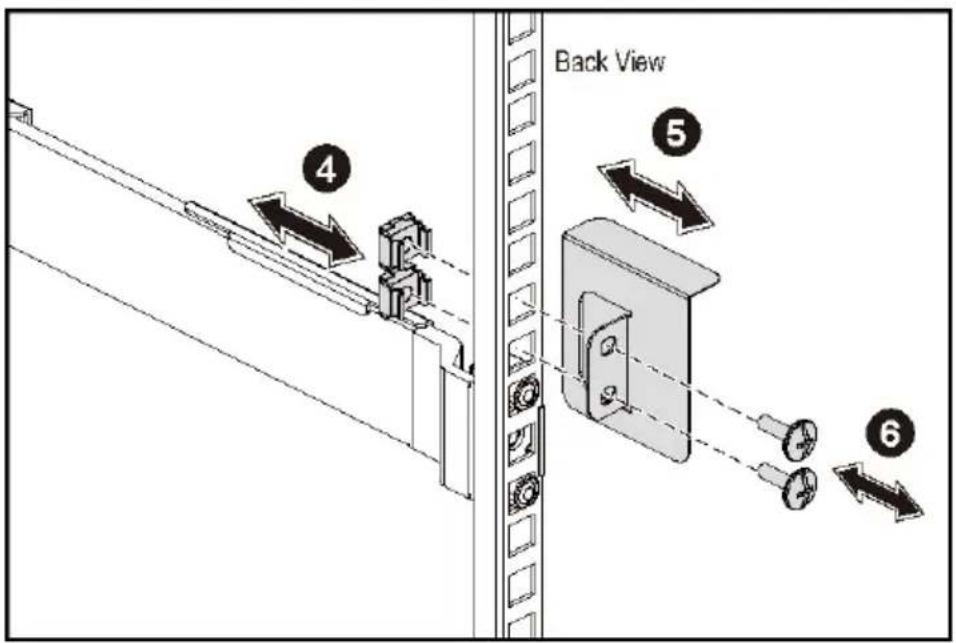
4 On each vertical rack flange on the back, put two screw bases into the two square holes right above the rail. See Figure 3.
5 Install the chassis stabilizer shipping brackets (optional) on the back rack flanges.
6 Install and tighten the screws.

NOTE: To transport systems already installed in the rack, ensure that the two chassis stabilizer shipping brackets (optional) are in place.
Figure 3. Installing the Chassis Stabilizer Shipping Brackets
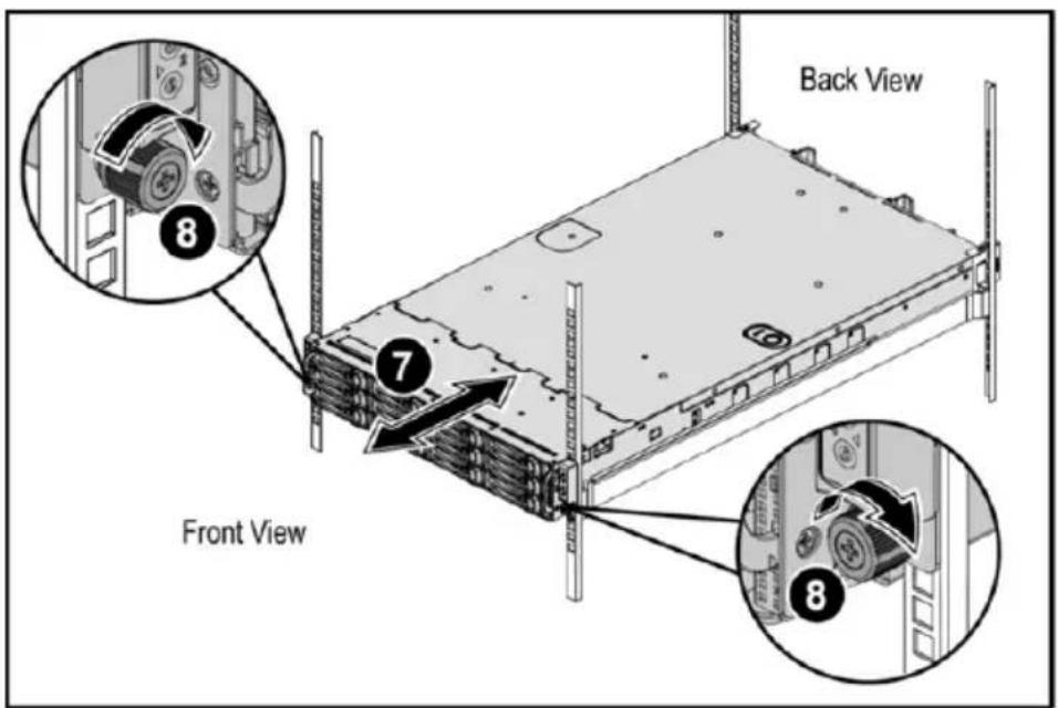
7 Slide the system into the rack. See Figure 4.
8 Tighten the thumbscrews to secure the ears of the system to the front of the rack flanges.
Figure 4. Installing the Chassis onto the Rack.
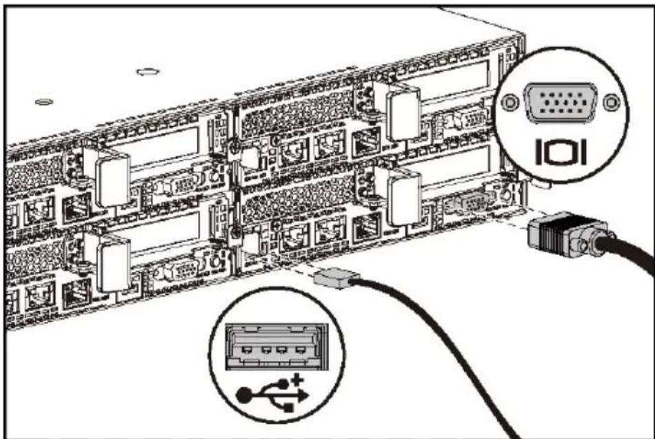
Optional—Connecting the Keyboard, Mouse, and Monitor
Figure 5. Optional—Connecting the Keyboard, Mouse and Monitor
natural_image
Diagram of a server rack connected to an I/O port via cable, showing internal components and connections (no text or labels)Connect the keyboard, mouse, and monitor (optional).
The connectors on the back of your system have icons indicating which cable to plug into each connector. Be sure to tighten the screws (if any) on the monitor's cable connector.

NOTE: Note that the system supports only one USB port and a micro USB port. If you require more than one USB outlet at a time, use USB Hub or Adapter Cable.
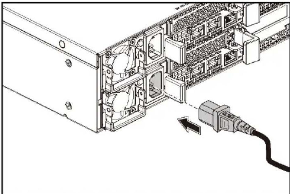
Connecting the Power Cable(s)
Figure 6. Connecting the Power Cable
natural_image
Technical line drawing of a server rack with an attached cable, showing internal components and connection (no text or symbols)Connect the system's power cable(s) to the system and, if a monitor is used, connect the monitor's power cable to the monitor. Plug the other end of the power cables into a grounded electrical outlet or a separate power source such as an uninterrupted power supply or a power distribution unit.

NOTE: The system supports both AC and HVDC power inputs. Your system can support up to two 1400 W power supply units (200-240 VAC nominal input voltage) or up to two 1600 W power supply units (200-240 VAC nominal input voltage). 1400 W power supply unit is supported only for China.
Turning on the System
Figure 7. Pressing the Power Button on the Front of the System
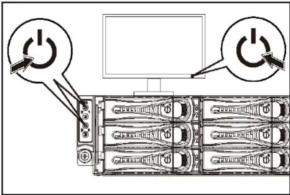
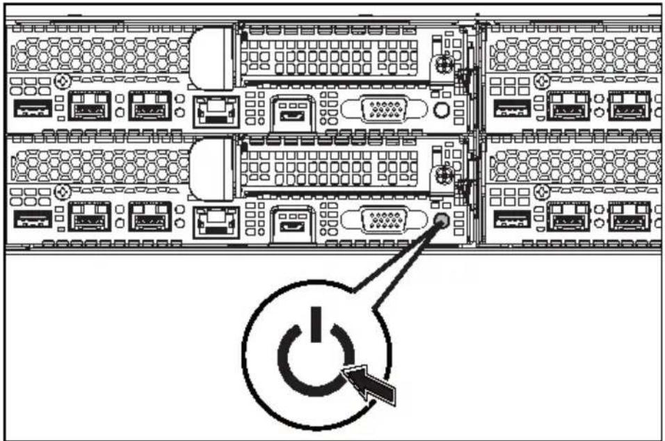
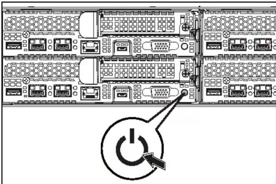
Figure 8. Pressing the Power Button on the Back of the System
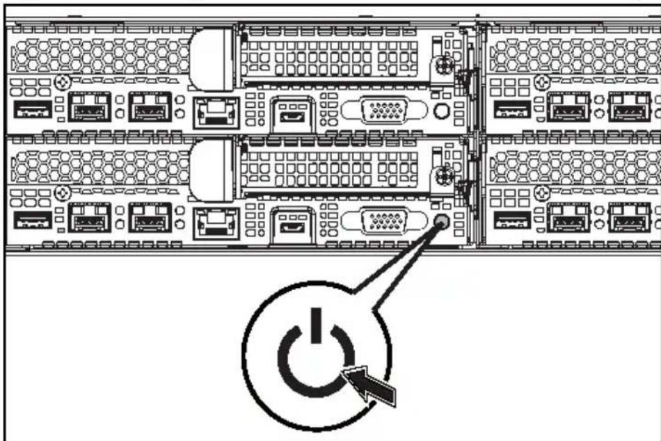
Press the power button(s) either on the front or back of the system. The power indicators should light green.
Complete the Operating System Setup
To install an operating system for the first time, see the installation and configuration documentation for your operating system. Be sure the operating system is installed before installing hardware or software not purchased with the system.

NOTE: See dell.com/ossupport for the latest information on supported operating systems.
Other Information You May Need

WARNING: See the safety and regulatory information that shipped with your system. Warranty information may be included within this document or as a separate document.
The Hardware Owner's Manual provides information about system features and describes how to troubleshoot the system and install or replace system components. This document is available at dell.com/support/home.
Dell systems management application documentation provides information about installing and using the systems management software. This document is available online at dell.com/support/home.
For an immediate access to your system information:
- Go to dell.com/support.
- Enter your system service tag in the Enter your Service Tag field.
- Click Submit.
The support page that lists the system manuals is displayed.
For more information about your system:
- Go to dell.com/support.
- Select your country from the drop-down menu on the top left corner of the page.
a. Select your product category.
b. Select your product segment.
c. Select your product.
The support page that lists the various support categories is displayed.

NOTE: Always check for updates on dell.com/support/home and read the updates first because they often supersede information in other documents.
NOM Information (Mexico Only)
The following information is provided on the device described in this document in compliance with the requirements of the official Mexican standards (NOM):
Supply voltage 200-240 V AC with 1400 W (for China
only) or 1600 W Power Supply Unit
Frequency
50/60
Hz
Current consumption 9 Amps with 1400 W Power Supply Unit
10 Amps with 1600 W Power Supply Unit
Technical Specifications
Processor
Two Intel Xeon E5-2600 v3
Memory
Architecture 1600 MT/s, 1866 MT/s, or
2133 MT/s DDR4 Registered DIMMs
Support for advanced ECC or memory optimized operation
Memory module sockets Twelve 288-pin
Memory module capacities (RDIMMs) 8 GB and 16 GB dual-rank
Minimum RAM
16 GB
Maximum RAM
Up to 256 GB
Power
NOTE: The system does not support a mixed installation of 1400 W and 1600 W power supply units.
NOTE: The 1400 W and 1600 W power supply units are hot swappable, and supports hot swap in any condition if the system has the power throttling feature.
AC power supply (per power supply)
Wattage 1400 W (for China only)
Voltage 200-240 VAC, 50/60 Hz, maximum
input current: 9 Amps
Heat dissipation 6024.376 BTU/hr maximum
Maximum inrush current
Initial In-rush Current cannot exceed 55 Amps (peak). Secondary In-rush Current cannot exceed 25 Amps (peak).
Wattage
1600
Voltage
200-240 VAC, 50/60 Hz, maximum input current: 10 Amps
Heat dissipation 6033.979 BTU/hr maximum
Maximum inrush current
Initial In-rush current and secondary In-rush current cannot exceed 50 Amps (peak).
HVDC power supply (per power supply)
Wattage 1400 W (for China only)
Voltage 240 VDC, 50/60 Hz, maximum input
current: 9 Amps
Heat dissipation 5440.614 BTU/hr maximum
Maximum inrush current
Initial In-rush Current cannot exceed 55 Amps (peak). Secondary In-rush Current cannot exceed 25 Amps (peak).
Battery (per system board)
System battery CR 2032 3.0-V lithium ion coin cell
Physical
Height 8.68 cm (3.42 in)
Width 44.8 cm (17.6 in)
Depth 79.0 cm (31.1 in)
Weight (maximum configuration) 41 kg (90.38 lb)
(with 12*3.5" HDD)
39 kg (86.00 lb)
(with 24*2.5" HDD)
Environmental
NOTE: For additional information about environmental measurements for specific system configurations, see www.dell.com/environmental_datasheets.
Temperature
Operating 10^ to 35^ C ( 50^ to 95^ F) with
a maximum temperature gradation of 10^ C per hour
NOTE: For altitudes above 2950 feet, the maximum operating temperature is derated 1^ F/550 ft.
CAUTION: The maximum number of memory modules and hard drives supported on 1U node configuration, with 135W and 145W processors, depends on the power supply installed.
Storage -40^ to 65^ ( -40^ to 149^ ) with
a maximum temperature gradation of 20^ C per hour
Relative humidity
Operating 20% to 80% (noncondensing) with
a maximum humidity gradation of 10% per hour
Storage 5% to 95% (noncondensing)
Maximum vibration
Operating 0.26 Grms at 5–350 Hz
Storage 1.88 Grms at 10–500 Hz for 15 min
Maximum shock
Operating One shock pulse in the positive
Storage Six consecutively executed shock
z axis (one pulse on each side of the system) of 31 G for 2.6 ms in the operational orientation
pulses in the positive and negative x, y, and z axes (one pulse on each side of the system) of 71 G for up to 2 ms;
Six consecutively executed shock pulses in the positive and negative x, y, and z axes (one pulse on each side of the system) of 27 G faired square wave pulse with velocity change at 235 inches/second (597 centimeters/second)
Altitude
Operating -15.2 to 3,048 m
Storage -15.2 to 10,668 m
Airborne Contaminant Level
Class G1 as defined by
(-50 to 10,000 ft.)
(-50 to 35,000 ft.)
ISA-S71.04-1985
Dell PowerEdge
C6320
系统使用入门
注、小心和警告

连接键盘、鼠标和显示器(可选)。
natural_image
Technical line drawing of a server rack with internal components and a cable inserted (no text or symbols)图 8。按下系统背面的电源按钮
natural_image
Diagram of a server rack with connected hardware components, showing I/O port and USB connection (no text or labels)natural_image
Technical line drawing of a server rack with an attached cable, showing internal components and connection (no text or symbols)Gambar 8. Menekan Tombol Daya di Bagian Belakang Sistem
natural_image
Diagram of a server rack connected to an I/O port via cable, showing internal components and connections (no text or labels)natural_image
Diagram of a computer tower internal structure with an attached cable showing connection (no text or symbols)natural_image
Diagram of a server rack with ports and a power button icon (no text labels)natural_image
Diagram of a server rack connected to an I/O port via cable, showing internal components and connection points (no text or symbols present)natural_image
Technical line drawing of a server rack with an attached cable and connector (no text or symbols)www.dell.com/support

03RKD9A00
- Dell PowerEdge
- C6320
- Getting Started
- With Your System
- Notes, Cautions, and Warnings
- CAUTION: Restricted Access Location
- Installation and Configuration
- Installing the Tool-Less Rail Solution
- Connecting the Power Cable(s)
- Turning on the System
- Complete the Operating System Setup
- Other Information You May Need
- NOM Information (Mexico Only)
- Technical Specifications
- Power
- HVDC power supply (per power supply)
- Battery (per system board)
- Physical
- Environmental
- 系统使用入门
- 注、小心和警告
Brand : DELL
Model : PowerEdge C6300
Category : Server