
CMPT-ISH98LR - Doorbell Infiniton - Free user manual and instructions
Find the device manual for free CMPT-ISH98LR Infiniton in PDF.


| Product Type | Cooker Hood (Range Hood) |
| Brand | Infiniton |
| Model | CMPT-ISH98LR |
| Installation Type | Chimney hood, ducted or recirculation |
| Control Type | Electronic touch panel and remote control |
| Number of Speeds | 4 (Low, Mid, High, Boost) |
| Boost Function | Yes, automatically reverts to High speed after 8 minutes |
| Lighting | LED, 1.5W, replaceable module |
| Grease Filter | Metal, washable in dishwasher |
| Charcoal Filter | Optional, replaceable (for recirculation mode) |
| Voltage | 220-240 V ~ 50 Hz |
| Exhaust Pipe Diameter | 120 mm minimum |
| Minimum Distance from Hob (gas) | 65 cm (may vary per hob instructions) |
| Safety Class | Class I (earthing required) |
| Timer Function | Yes, delay shut-off (3 minutes) and programmable countdown |
| Clock | Yes, with setting function |
| Remote Control | Infrared remote included |
| Light Control | Independent on/off from fan |
| Accessories Included | Decorative chimney sections, exhaust pipe, hanger assembly, screws, wall plugs |
| Filter Maintenance | Grease filter every 2 months; charcoal filter every 4 months |
Frequently Asked Questions - CMPT-ISH98LR Infiniton
User questions about CMPT-ISH98LR Infiniton
0 question about this device. Answer the ones you know or ask your own.
Ask a new question about this device
Download the instructions for your Doorbell in PDF format for free! Find your manual CMPT-ISH98LR - Infiniton and take your electronic device back in hand. On this page are published all the documents necessary for the use of your device. CMPT-ISH98LR by Infiniton.
USER MANUAL CMPT-ISH98LR Infiniton
natural_image
Line drawing of a tall industrial chimney mounted on a base with control panel and indicator lights (no text or symbols)Manual del usuario
modelo: CMPT-ISH99X
CMPT-ISH98LR
CMPT-ISH97WG
natural_image
Simple line drawing of a laboratory setup with a conical flask, heating a test tube, and a control panel (no text or symbols)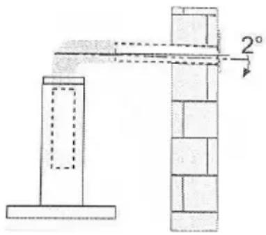
natural_image
Simple line drawing of a house with a stove and fire, no text or symbols presentnatural_image
Technical line drawing of a mechanical assembly with a cylindrical component mounted on a base (no text or symbols)natural_image
Technical line drawing of a mechanical assembly with vertical supports and a central cylindrical component (no text or symbols)natural_image
Isometric line drawing of a mechanical component with a downward arrow indicating force or direction (no text or symbols)natural_image
Illustration of a remote control with icons including sun, power button, flower, and leaf (no text or symbols)FILTROS DE GRASA
LIMPIEZA DE METALES AUTOPORTANTE EN FILTROS DE GRASA
natural_image
Line drawings showing three steps of a device operation: opening, holding cable, and inserting into a wall-mounted device (no text or symbols present)The instructions for Use apply to several versions of this appliance. Accordingly, you
may find descriptions of individual features that do not apply to your specific appliance.
INSTALLATION
● The manufacturer will not be held liable for any damages resulting from incorrect or improper installation.
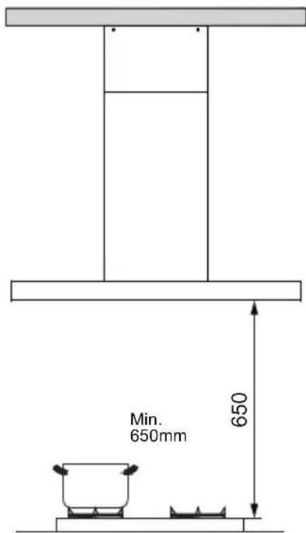
- The minimum distance between the supporting surface for the cooking vessels on the hob and the lowest part of the range hood. ( When the range hood is located above a gas appliance, this distance shall be at least 65 cm. If the instructions for installation for the gas hob specify a greater distance, this has to be taken into account. The distance of 65 cm can be reduced for:non-combustible parts of range hoods, and parts operating at safety extra low voltage,Provided these parts do not give access to live parts if deformed;)
- Check that the mains voltage corresponds to that indicated on the rating plate fixed to the hood.
- For Class I appliances, check that the domestic power supply guarantees adequate earthing.
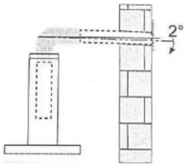
- Connect the extractor to the exhaust flue through a pipe of minimum diameter 120mm. The route of the flue must be as short as possible.
● The air must not be discharged into a flue that is used for exhausting fumes from appliances burning gas or other fuels.
- If the extractor is used in conjunction with non-electrical appliances (e.g. gas burning appliances), a sufficient degree of aeration must be guaranteed in the room in order to prevent the backflow of exhaust gas. The kitchen must have an opening communicating directly with the open air in order to guarantee the entry of clean air.
- When the cooker hood is used in conjunction with appliances supplied with energy other than electric, the negative pressure in the room must not exceed 0.04 mbar to prevent fumes being drawn back into the room by the cooker hood.
- If the supply cord is damaged, it must be replaced by the manufacturer, its service agent or similarly qualified persons in order to avoid a hazard.
● Regulations concerning the discharge of air have to be fulfilled.
natural_image
Simple line drawing of a heating lamp with a conical shade emitting steam, no text or symbols present.USE
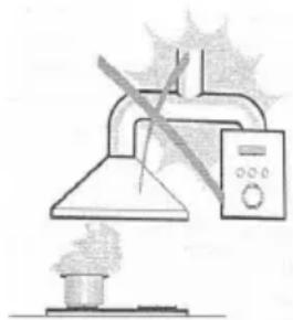
● The cooker hood is only for home use, not suitable for barbecue, roast shop and other commercial purposes.
● Never use the hood for purposes other than for which it has been designed.
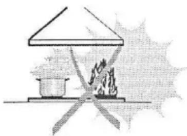
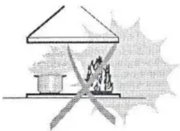
● Never leave high naked flames under the hood when it is in operation.
- Adjust the flame intensity to direct it onto the bottom of the pan only, making sure that it does not engulf the sides.
- Deep fat fryers must be continuously monitored during use: overheated oil can burst into flames.
● Do not flame under the range hood; risk of fire.
- This appliance can be used by children aged from 8 years and above and persons with reduced physical, sensory or mental capabilities or lack of experience and knowledge if they have been given supervision or instruction concerning use of the appliance in a safe way and understand the hazards involved.
● Children should be supervised to ensure that they do not play with the appliance.
● Cleaning and user maintenance shall not be made by children without supervision.
● "CAUTION: Accessible parts may become hot when used with cooking appliances".
MAINTENANCE
● The cooker hood and its filter should be cleaned regularly according to the instruction.
- Switch off or unplug the appliance from the mains supply before carrying out any maintenance work.
● Clean and/or replace the Filters after the specified period(Fire hazard).
● Clean the hood using a damp cloth and a neutral liquid detergent.
● The appliance uses 4 hob elements at most.
natural_image
Simple line drawing of a house with a chimney and fire, no text or symbols present
The symbol — is packaging indicates that this product may not be treated as household waste. Instead it shall be handed over to the applicable collection point for the recycling of electrical and electronic equipment. By ensuring this product is disposed of correctly, you will help prevent potential negative consequences for the environment and human health, which could otherwise be caused by inappropriate waste handling of this product. For more detailed information about recycling of this product, please contact your local city office, your household waste disposal service or the shop where you purchased the product.
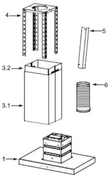
| Ref. Qty. Product Components | ||
| 1 | 1 | Hood Body,complete with: Controls, Light, Blower,Filter. |
| 3.1 | 1 | Lower Decorative Chimney |
| 3.2 | 1 | Upper Decorative Chimney |
| 4 | 1 | Hanger Assembly |
| 5 | 4 | Hanger |
| 6 | 1 | Exhaust pipe |
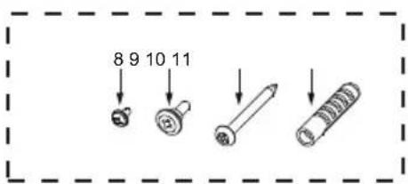
| Ref. Qty. Installation Components | ||
| 8 | 14 | Screws M4*8 (4 spare screws included) |
| 9 4 Decorative Screws Assembly(no need for this hood) | ||
| 10 | 4 | Screws ST5*50 |
| 11 | 4 | Wall Plugs |
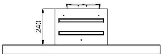
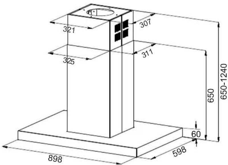
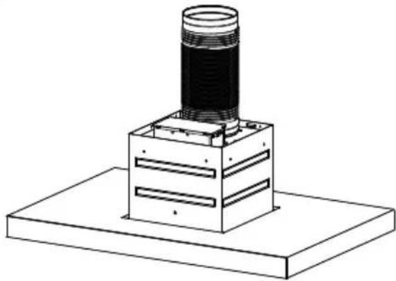
- Install the Exhaust pipe to the Hood body.
natural_image
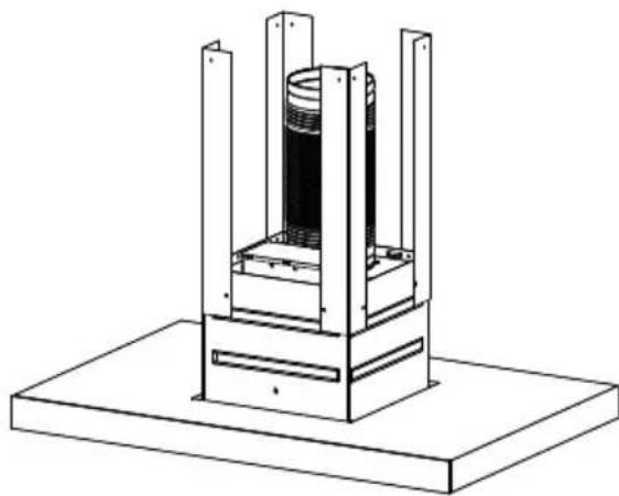
Technical line drawing of a mechanical assembly with a cylindrical component mounted on a base (no text or symbols)- Fasten the 4 Hanger to the Hood Body assembly with 8 Screws (M4*8) according to the image below.
natural_image
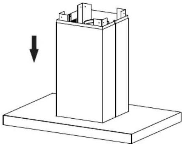
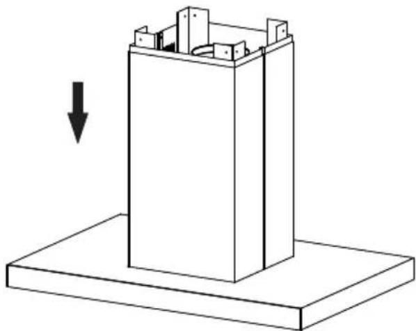
Technical line drawing of a mechanical assembly with vertical supports and a central cylindrical component (no text or symbols)- Assemble the Lower Decorative Chimney and the Upper Decorative Chimney to the Hood body assembly.
natural_image
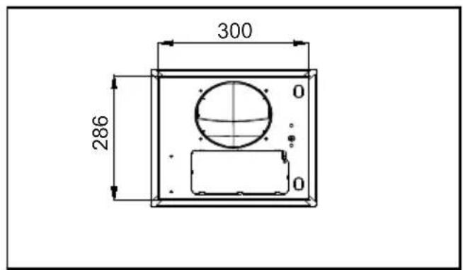
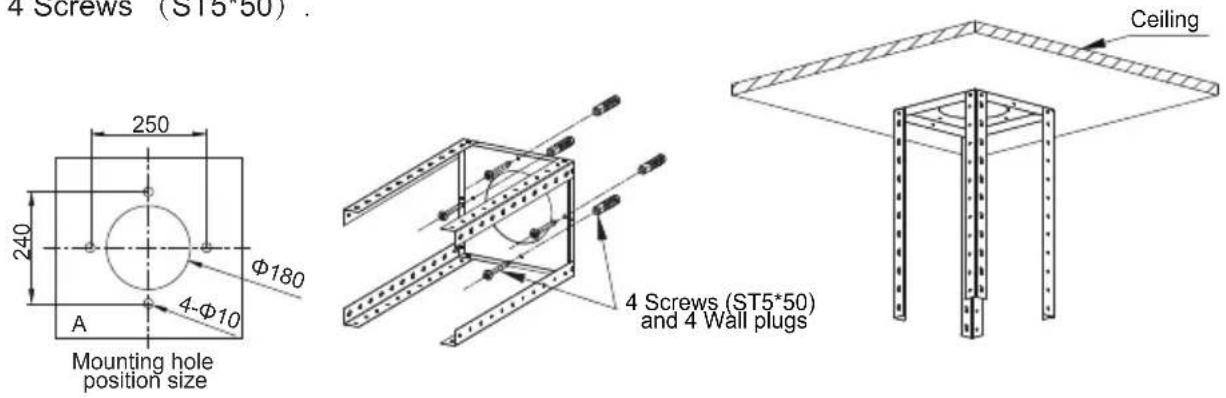
Isometric line drawing of a mechanical component with a downward arrow indicating force or direction (no text or symbols)- Drill holes according to the Figure A with a 10mm drill bit; and then insert the wall plugs into the holes; Finally Fasten the adjustment hanger assembly to the ceiling by 4 Screws (ST5*50).
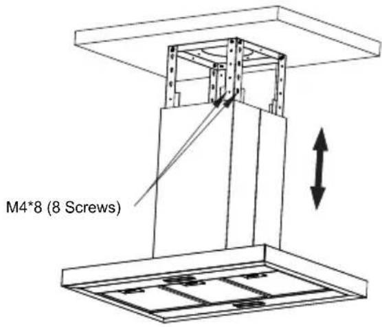
- Fasten the Hood Body Assembly to the adjustment hanger assembly by using 8 Screws (M4*8).
-
Drag up the exhaust pipe and connect it to the public smoke exhaust system; in the meantime, connect the cord to the socket.
-
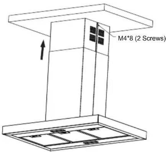
Drag up the Upper Decorative Chimney until the Upper Decorative Chimney touch the ceiling, fasten with 2 Screws (M4*8).
Speed adjustment(for some models).
- After plugging, buzz once to declare the hood is connected with electricity. After the connection:
- Press the Light button, control light being on and off independently. Press it once, the lights will be on. Press again, they will be off.
- Press the Low button, control low speed being on and off independently. Press it once, the low speed key light is on and motor run at low speed. Press again, they will be off.
- Press the Mid button, control middle speed being on and off independently. Press it once, the mid speed key light is on and motor run at mid speed. Press again, they will be off.
- Press the High button, control high speed being on and off independently. Press it once, the high speed key light is on and motor run at high speed. Press again, they will be off.
- Press the Boost button, control boost speed being on and off independently. Press it once, the boost speed key light is on and motor run at boost speed. Press again, they will be off. The Boost speed will automatically revert to High speed after running 8 minutes.
| B |
Light
Low
Mid
High
Boost
Speed adjustment(for some models).
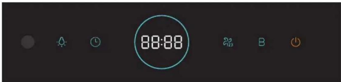
The keys from left to right are light, clock/timing, speed, booster and power.
power up1.
1.1 once power up, the buzzing starts, the screen elements are all displayed, the key lights are all lit up and continue for 1S. During the period, the key operation does not respond. After 1S, the key operation enters the shutdown state. The screen display is 12:00, and the key lights are off. At this time, the remote control operation can be responded.
2."power" function
2.1 Under on standby condition:
Press the "power" key to enter the constant speed operation, and the speed is "memory speed" (that is, the last adjustment of the user's constant speed).
1-3 speed is valid, the first power on default 2 speed, booster and delay shutdown of 1 speed do not participate in "memory".
2.2 Under working condition:
Short press the "power" button, the whole machine is adjusted to the delayed shutdown state, the speed is adjusted to 1 speed, the screen shows 3MIN countdown, the aperture is all bright.
2.3 Under delayed shutdown condition:
Short press "power" button to shut down;
3. Light function
When the fan is closed, the light is synchronously closed. In other times, the "light" function can be operated independently. The "light" key is pressed short to switch the light function, and the light is closed in any form of shutdown or error reporting.
4. Adjustment of "Speed"
4.1 In the shutdown state, press the "power" button to enter the constant speed operation state, and the "power" and "speed" lights are all on.
4.2 In the startup state, the screen shows the speed in the middle, 1-3 in the constant speed, and B in the booster:
A. Shortly press the "B" key, which will switch between B speed and the 3 speed.
B. Shortly press the "speed" key, it will switch between 1-3 speed in cycles.
C. There is no operation under B speed. After 3 minutes, it will automatically run in 3 speed.
D. Press the "power" key and enter the state of delayed shutdown. The "speed" and "B" lights go out. The "power" lights flicker.
4.3 In the state of delayed shutdown:
A. Press the "B" key and enter the B speed. The "B" key is always on, the "speed" lamp is off, and the "power" lamp is always on.
B. Press the "speed" key and enter the start-up mode of constant speed (adjusting to the last constant speed). The "speed" and "power" lights are always on and the "B" lights are off.
5. Clock function
On standby :
5.1 Press the clock/timing button, the clock/timing button light is always on, the hour flashes, the minute is always on, then press the "wind speed" button to adjust the hour and the long press to adjust quickly; press the "clock/timing" button again, the hour is always on, the minute flickers, press the "wind speed" button to adjust the minute, and the long press to adjust quickly; press the "clock/timing" button again, the end time will be set.
5.2 In the process of setting up, the 5S keyless will end setting, restore standby state and save the adjusted time.
6."Timing" function (error (+10%)
In "B" speed or "Constant" speed
6.1 If the current timing function is not enabled, the timing function is enabled by pressing the "clock/timing key" for a long time. The timing key lights up and the screen displays the timing time in the format of "hour: minutes" without leading zeros.
6.2 If the current timing function has been enabled, the setting time can be switched by pressing the "clock/timing key" (7 options can be chosen: 15 min, 30 min, 45 min, 1 h, 1.5 h, 2 h, 3 h). When switching to a new timing time, the screen displays flickering for 3 seconds (including colons). If there is no operation in the flickering process, the current timing time will be applied to start countdown and the screen display stops flickering (colon remains scintillating), refresh display remaining time (step value is 1 min);
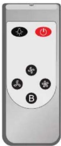
7. Infrared remote control function
Press the corresponding button on the remote controller, which can control the switch and speed adjustment of the hood and the opening and closing of the lighting.
| Button Function | Remarks | |
 | Turns the Motor ON. | When  |
| Enable shutdown the Motor with a 3 minutes delay meanwhile flashes. | When [BTCH] | |
| Turns the Motor OFF. | When  | |
 | Turns the Motor on at speed Low. | Buttons [CHYS] |
 | Turns the Motor on at speed Medium. | Buttons  |
| [SHCA] | Turns the Motor on at speed High. | Buttons  |
 | Turns the Lighting System on and off at maximum intensity. | Button  |
 | Turns the Motor on at speed BOOST. | Buttons [SA63] |
natural_image
Illustration of a remote control with icons for lights, power button, and fan (no text or symbols)GREASE FILTERS
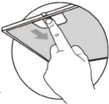
CLEANING METAL SELF-SUPPORTING GREASE FILTERS
- The filters must be cleaned every 2 months of operation, or more frequently for particularly heavy usage, and can be washed in a dishwasher.
● Pull the comfort panels to open them. - Remove the filters one by one pushing them towards the back side of the hood unit and simultaneously pulling downwards.
- Any kind of bending of the filters has to be avoided when washing them. Before fitting them again into the hood make sure that they are completely dry. (The color of the filter surface may change throughout the time but this has no influence to the filter efficiency)
- When fitting the filters into the hood pay attention that they are mounted in correct position the handle facing outwards.
natural_image
Illustration of a hand interacting with a tablet device, showing a finger pointing at the screen (no text or symbols present)ACTIVATED CHARCOAL FILTER (RECIRCULATION VERSION)
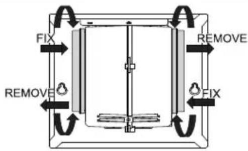
These filters are not washable and cannot be regenerated, and must be replaced approximately every 4 months of operation, or more frequently with heavy usage.
REPLACING THE ACTIVATED CHARCOAL FILTER
- Remove the metal grease filters.
- Remove the saturated activated charcoal filter.
- Fit the new filters.
- Replace the metal grease filters.
LIGHT REPLACEMENT
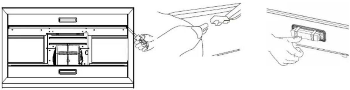
Replacing the light modules
● You cannot replaced the light bulbs, the entire light module has to be replaced.
- When changing the light modules, the contacts are live.
- Before changing the light module(s), unplug the appliance from the mains or switch off the circuit breaker in the fuse box.
- Remove the grease filter and carefully remove the 2 screws from the front plate (a cross headed screwdriver will be needed to remove the screws).
- Disconnect the terminal of LED light.
- Press LED light on the back of the front plate, take the LED light out.
- Replace the lamp(commercially available LED lamp (max.1.5w).
natural_image
Line drawings showing three steps of installing or adjusting a device panel, from open to closed (no text or symbols present)| Max Power | Voltage | Picture Lamp Cap ILCOS D code | |||
| Square / Diameter: 33.2mm x 120mm | 1.5W DC | 12 V | 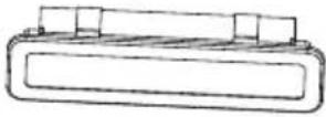 | — — | DSS-1.5-S-33.2/120 |
- Press LED light on the front of front plate, install the LED light on the front plate.
- Connect the terminal of LED light and light leads.
- Carefully fasten the 2 screws on the front plate, reinstall the grease filter.
DISPOSAL OF OLD ELECTRICAL APPLIANCES
The European directive 2012/19/EU on Waste Electrical and Electronic Equipment (WEEE), requires that old household electrical appliances must not be disposed of in the normal unsorted municipal waste stream. Old appliances must be collected separately in order to optimize the recovery and recycling of the materials they contain, and reduce the impact on human health and the environment.
The crossed out "wheeled bin" symbol on the product reminds you of your obligation, that when you dispose of the appliance, it must be separately collected.
Consumers should contact their local authority or retailer for information concerning the correct disposal of their old appliance.
| Fault Cause Solution | ||
| Light on, but motor does not work | The blades are blocked. | Check the blades. |
| The capacitor is damaged. Replace capacitor. | ||
| The motor is damaged. Replace motor. | ||
| The internal wiring of motor is cut off/disconnected. An unpleasant smell may be produced. | Replace motor. | |
| Both light and motor do not work | Apart from the above mentioned, check the following: | |
| Light damaged. Replace lights. | ||
| Power cord loose. | Connect the wires as the electric diagram. | |
| Oil leakage | Outlet and the air ventilation entrance are not tightly sealed. | Take down the outlet and seal with glue. |
| Vibration | The blade, if damaged, can cause vibrating. | Replace the blade. |
| The motor is not tightly fastened. Fasten the motor tightly. | ||
| The cooker hood is not tightly fixed. Fixed the cooker hood tightly. | ||
| Insufficient suction | The distance between the cooker hood and the cooker top is too large. | Readjust the distance. |
| Too much ventilation from open doors or windows. | Choose a new place to install the appliance or close some doors / windows. | |
| The machine inclines | The fixing screws are not tight enough. | Tighten the fixing screw and make it horizontal. |
| The hanging screws are not tight enough | Tighten the hanging screw and make it horizontal. | |

natural_image
Simple line drawing of a heating lamp with a conical shade emitting steam, no text or symbols present.USE
natural_image
Technical line drawing of a mechanical assembly with a cylindrical component mounted on a base (no text or symbols)natural_image
Technical line drawing of a mechanical assembly with vertical supports and a central cylindrical component (no text or symbols)- Monte a chaminé decorativa inferior e a chaminé decorativa superior no conjunto do corpo do capô.
natural_image
Isometric line drawing of a mechanical component with a downward arrow indicating force or motion (no text or symbols)Luz Baixa
Mid
Alta
Boost
natural_image
Close-up of a remote control with black buttons and a red play button (no text or symbols visible)FILTRO DE GRAXA
natural_image
Hand pointing at a device screen with a downward arrow, enclosed in a circular frame (no text or symbols)FILTRO DE CARBONO ACTIVO (OPCIONAL - NÃO INCLUIDO)
natural_image
Line drawings showing three steps of a device assembly: opening, holding a tool, and inserting into a device (no text or symbols present)INFINITON WORLD ELECTRONIC S.I.
C/Baza 349, naves 4-6
Poligono Juncar
18220 ALBOLOTE (Granada)
e-mail: info@infiniton.es
INFINITON
INFINITON
TARJETA DE GARANTÍA
Modelo
N° de serie ____
- Manual del usuario
- FILTROS DE GRASA
- INSTALLATION
- USE
- MAINTENANCE
- Speed adjustment(for some models).
- Light function
- Adjustment of "Speed"
- In the state of delayed shutdown:
- Clock function
- On standby :
- Infrared remote control function
- GREASE FILTERS
- CLEANING METAL SELF-SUPPORTING GREASE FILTERS
- ACTIVATED CHARCOAL FILTER (RECIRCULATION VERSION)
- REPLACING THE ACTIVATED CHARCOAL FILTER
- LIGHT REPLACEMENT
- Replacing the light modules
- DISPOSAL OF OLD ELECTRICAL APPLIANCES
- FILTRO DE GRAXA
- FILTRO DE CARBONO ACTIVO (OPCIONAL - NÃO INCLUIDO)
- INFINITON
- TARJETA DE GARANTÍA
Brand : Infiniton
Model : CMPT-ISH98LR
Category : Doorbell