
Mach - Central heating boiler FERROLI - Free user manual and instructions
Find the device manual for free Mach FERROLI in PDF.


| Product Type | Floor-standing condensing central heating boiler |
| Models | MACH 150, 225, 300, 370, 450, 520, 600 |
| Rated Heat Output (Pn) | 139 kW (MACH 150) to 557 kW (MACH 600) |
| Min. Heat Output | 14 kW (all models) |
| Efficiency at 30% load (low temperature) | 108.8% |
| Efficiency at Pmax (80/60°C) | 98% |
| Gas Types | Natural Gas (G20) and LPG (G31) |
| Power Supply | 230V ~ 50Hz |
| Max. Working Pressure (Heating) | 6 bar |
| Min. Working Pressure (Heating) | 0.8 bar |
| Max. Adjustment Temperature (Heating) | 95°C |
| Water Content (Heating) | 24 L (MACH 150) to 90 L (MACH 600) |
| Weight (Empty) | 215 kg (MACH 150) to 500 kg (MACH 600) |
| Protection Rating | IPX4D |
| Flue Connection Diameter | 200 mm |
| System Flow/Return Connections | DN65 flanged |
| Gas Inlet Connection | DN40 flanged |
| Control Panel | LCD display with contextual buttons, menu navigation, time programming, sliding temperature control |
| Safety Features | Frost protection, anti-legionella, safety thermostat, overheat protection |
| Maintenance | Periodic by qualified personnel; cleaning and condensate drain |
Frequently Asked Questions - Mach FERROLI
User questions about Mach FERROLI
0 question about this device. Answer the ones you know or ask your own.
Ask a new question about this device
Download the instructions for your Central heating boiler in PDF format for free! Find your manual Mach - FERROLI and take your electronic device back in hand. On this page are published all the documents necessary for the use of your device. Mach by FERROLI.
USER MANUAL Mach FERROLI
natural_image
Three black industrial electrical cabinets with visible cooling fans and mounting feet (no text or symbols)CE
| IT | ISTRUZIONE PER L'USO L'INSTALLAZIONE E LA MANUTENZIONE |
| ES | INSTRUCCIONES DE USO, INSTALACIÓN Y MANTENIMIENTO |
| RO | INSTRUCTIUNI DE UTILIZARE, INSTALARE ŞI ÎNTRETINERE |
| PL | INSTRUKCJA UŻYTKOWANIA, INSTALOWANIA I KONSERWACJI |
| EN | INSTRUCTIONS FOR USE, INSTALLATION AND MAINTENANCE |

fig. 20

fig. 23 fig. 24


flowchart
graph TD
    A[" "] --> B["5"]
    C[" "] --> D["6"]
    D --> E["OK"]
    E --> F["7"]
fig. 25
fig. 26
natural_image
Technical line drawing of a rectangular industrial machine with mounting base and side supports (no text or symbols)Posizionamento
$$ A = F A S E A P E R T U R A $$
$$ B = N E U T R O $$
$$ C = F A S E C H I U S U R A $$
a 1a zona (diretta)
fig. 54

natural_image
Technical line drawing of a mechanical assembly with no visible text or symbolsfig. 56

natural_image
Technical line drawing of an industrial machine with internal components and directional arrows indicating flow or movement (no text or symbols present)fig. 55

natural_image
Technical line drawing of an industrial machine with internal components and piping (no text or symbols)fig. 57
natural_image
Technical line drawing of a mechanical device with cylindrical components and mounting flanges (no text or symbols)fig. 59

natural_image
Line drawing of a rectangular industrial machine with a cylindrical component and wheels, no text or symbols presentfig. 60

natural_image
Technical line drawing of a mechanical device with cylindrical components and mounting flanges (no text or symbols)fig. 61

natural_image
Technical line drawing of a mechanical assembly with multiple components and mounting flanges (no text or symbols)natural_image
Technical line drawing of a mechanical assembly with labeled components (no text or symbols beyond labels)natural_image
Technical line drawing of a mechanical pump assembly with mounting flanges and a labeled component 'F' (no text or symbols beyond label)fig. 67
fig. 68
fig. 71
fig. 72
natural_image
Technical line drawing of industrial piping and valves with a black arrow indicating direction (no text or symbols)natural_image
Technical line drawing of a mechanical assembly with no visible text or symbolsnatural_image
Technical line drawing of a mechanical assembly with no visible text or symbolsfig. 86 - Apertura coperchio
- Agganciare la staffa (Vedi fig. 87)
natural_image
Line drawing of a mechanical device with open lid, flanges, and internal components (no text or symbols)
natural_image
Technical line drawing of a mechanical assembly with no visible text or symbolsfig. 87
natural_image
Technical line drawing of an industrial machine with internal components and mounting brackets (no text or symbols)fig. 88
Manutenzione moduli
natural_image
Mechanical diagram showing two configurations of a valve assembly with tubing and a pipe, no text or symbols present.fig. 90
Legenda figure cap. 4
II2HM3P (IT) II2H3P (ES) II2H3P (RO) II2E3P (PL) II2EK3P (NL) I2Hs (HU)
MODELLO: MACH 150 - (OMCMFAWA)
fig. 20
fig. 21


flowchart
graph TD
    A["Step 1"] --> B["Step 2"]
    B --> C{OK}
    C -->|6| D["Step 3"]
    D --> E["Step 4"]
fig. 25
natural_image
Technical line drawing of a rectangular industrial machine with mounting base and side supports (no text or symbols)Emplazamiento
$$ A = F A S E D E A P E R T U R A $$
$$ B = N E U T R O $$
$$ C = F A S E D E C I E R R E $$
a 1ª zona (directa)
b Circuito del acumulador
M Ida
R Retorno
K1 - K2bobina 230 Vca, < 2,2 VA
$$ \text { contacto } 2 3 0 \mathrm{Vca} , > 8 \mathrm{A} $$
natural_image
Pure architectural floor plan lines without any text, numbers, or symbolsfig. 54

natural_image
Technical line drawing of a mechanical assembly with no visible text or symbolsfig. 56
natural_image
Technical line drawing of an industrial machine with internal components and directional arrows indicating flow or movement (no text or symbols present)fig. 55

natural_image
Technical line drawing of an industrial machine with internal components and piping (no text or symbols)fig. 57

natural_image
Technical line drawing of a mechanical device with cylindrical components and mounting flanges (no text or symbols)fig. 59

natural_image
Line drawing of a rectangular industrial machine with internal pipes and wheels, no text or symbols presentfig. 60

natural_image
Technical line drawing of a mechanical device with pipes and mounting flanges (no text or symbols)fig. 61

natural_image
Technical line drawing of a mechanical assembly with multiple components and mounting feet (no text or symbols)natural_image
Technical line drawing of a mechanical assembly with a pump and a rotating component (no text or symbols)fig. 65
fig. 66
natural_image
Technical line drawing of a mechanical pump assembly with mounting flanges and a labeled component 'F' (no text or symbols beyond label)fig. 67
fig. 68
fig. 71
fig. 72
natural_image
Technical line drawing of industrial piping and valves with a black arrow indicating direction (no text or symbols)natural_image
Technical line drawing of a mechanical assembly with no visible text or symbolsnatural_image
Technical line drawing of a mechanical assembly with no visible text or symbolsnatural_image
Line drawing of a mechanical device with open lid, flanges, and internal components (no text or symbols)
natural_image
Technical line drawing of a mechanical assembly with no visible text or symbolsfig. 87
natural_image
Technical line drawing of an industrial machine with internal components and mounting brackets (no text or symbols)fig. 88
natural_image
Mechanical diagram showing two configurations of a valve assembly with tubing and pipe fittings (no text or labels)fig. 90
II2HM3P (IT) II2H3P (ES) II2H3P (RO) II2E3P (PL) II2EK3P (NL) I2Hs (HU)
II2HM3P (IT) II2H3P (ES) II2H3P (RO) II2E3P (PL) II2EK3P (NL) I2Hs (HU)
MODELO: MACH 150 - (0MCMFAWA)
flowchart
graph TD
    A["Group A"] --> B["Group B"]
    B --> C["Group C"]
    D["Group D"] --> E["Group E"]
    E --> F["Group F"]
    G["Group G"] --> H["Group H"]
    H --> I["Group I"]
    J["Group J"] --> K["Group K"]
    K --> L["Group L"]
    M["Group M"] --> N["Group N"]
    N --> O["Group O"]
    P["Group P"] --> Q["Group Q"]
    Q --> R["Group R"]
    S["Group S"] --> T["Group T"]
    T --> U["Group U"]
    V["Group V"] --> W["Group W"]
    W --> X["Group X"]
    Y["Group Y"] --> Z["Group Z"]
    Z --> AA["Group AA"]
    AB["Group AB"] --> AC["Group AB"]
    AC --> AD["Group AD"]
Excludere boiler (economy)
C

flowchart
graph TD
    A["1"] --> B["2"]
    C["5"] --> D["3"]
    E["7"] --> F["4"]
    G["OK"] --> H["OK"]
fig. 11- Reglarea orei
Oprirea centralei

fig. 14

fig. 15
Reglarea temperaturii apei calde menajere (cu boiler optional instalat)
Accesati meniul „Temp. de reglare” pentru a modifica temperatura de la un minim de 10°C la un maxim de 65°C. Confirmați cu tasta OK.


fig. 16
Reducerea temperaturii apei calde menajere (cu boiler optional instalat)

fig. 17
fig. 18
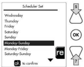
fig. 19
fig. 20

fig. 22

flowchart
graph TD
    A["1"] --> B["2"]
    C["△"] --> D["OK"]
    E["7"] --> F["△"]
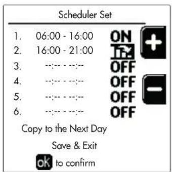

fig. 23 fig. 24

flowchart
graph TD
    A["Step 1"] --> B["Step 2"]
    B --> C{OK}
    C -->|6| D["Step 3"]
    D --> E["Step 4"]
fig. 25
fig. 26
fig. 27

fig. 29- Curba de compensare
natural_image
Technical line drawing of a rectangular industrial machine with mounting base and side-mounted components (no text or symbols)Pozitionarea
fig. 38
fig. 39
fig. 40
$$ A = F A Z A D E D E S C H I D E R E $$
$$ B = N E U T R U $$
$$ C = F A Z A D E \hat {I} N C H I D E R E $$
a Zona 1 (directă)
b Circuit boiler
M Tur
R Retur
K1 - K2bobina 230 V c.a., < 2,2 VA contact 230 V c.a., > 8A
natural_image
Pure electrical circuit lines without any symbolsfig. 54

natural_image
Technical line drawing of a mechanical assembly with no visible text or symbolsfig. 56

natural_image
Technical line drawing of an industrial machine with internal components and directional arrows indicating flow or movement (no text or symbols present)fig. 55

natural_image
Technical line drawing of an industrial machine with internal components and piping (no text or symbols)fig. 57

fig. 58- Panoul de borne electric

Sarcini maxime aplicabile:
natural_image
Technical line drawing of a mechanical device with cylindrical components and mounting flanges (no text or symbols)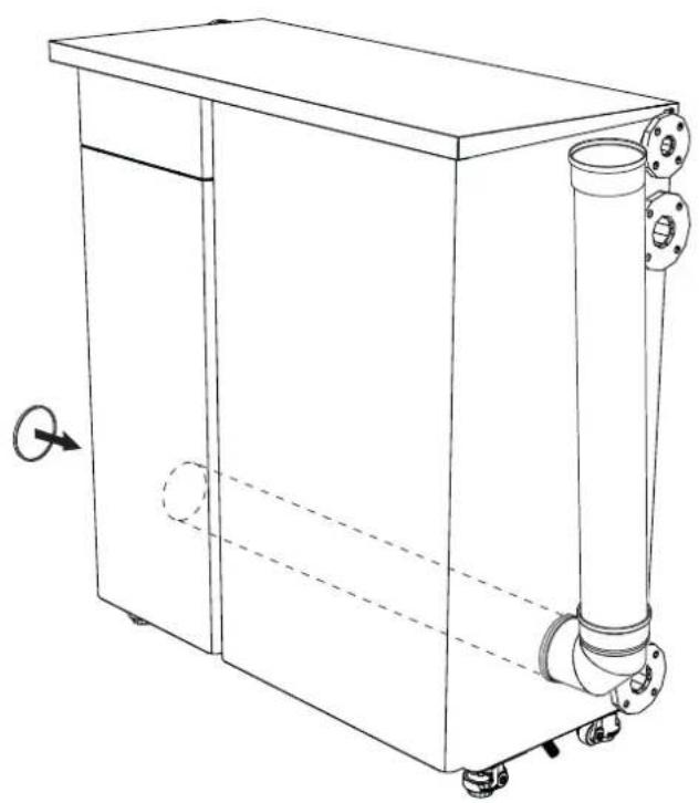
natural_image
Line drawing of a rectangular industrial machine with internal pipes and mounting feet (no text or symbols)fig. 60
natural_image
Technical line drawing of a mechanical device with pipes and mounting flanges (no text or symbols)fig. 61

natural_image
Technical line drawing of a mechanical assembly with no visible text or symbolsnatural_image
Technical line drawing of a mechanical assembly with labeled components (no text or symbols beyond labels)natural_image
Technical line drawing of a mechanical pump assembly with mounting flanges and a labeled component 'F' (no text or symbols beyond label)fig. 67
fig. 68
fig. 71
fig. 72
natural_image
Technical line drawing of industrial piping and valves with a black arrow indicating direction (no text or symbols)natural_image
Technical line drawing of a mechanical assembly with no visible text or symbolsfig. 79- Šurubul de reglare a debitului maxim
Reglarea CO₂ la debitul termic minim
natural_image
Technical line drawing of a mechanical assembly with no visible text or symbolsfig. 80- Şurubul de reglare a debitului minim OFFSET
REPETAȚI ÎNTREAGA PROCEDURĂ DE CONTROL A ARDERII PENTRU TOATE MODULELE CENTRALEI.

natural_image
Technical line drawing of a mechanical device with an inset close-up showing internal components (no text or symbols)fig. 87
natural_image
Technical line drawing of an industrial electrical cabinet with internal components and mounting flanges (no text or labels)fig. 88
natural_image
Mechanical diagram showing two configurations of a piping system with hoses and valves (no text or labels)fig. 90
3.4 Rezolvarea problemelor
Diagnosticarea
CATEGORIE GAZ II2HM3P (IT) II2H3P (ES) II2H3P (RO) II2E3P (PL) II2EK3P (NL) I2Hs (HU)
II2HM3P (IT) II2H3P (ES) II2H3P (RO) II2E3P (PL) II2EK3P (NL) I2Hs (HU)
CATEGORIE GAZ
II2HM3P (IT) II2H3P (ES) II2H3P (RO) II2E3P (PL) II2EK3P (NL) I2Hs (HU)
C

flowchart
graph TD
    A["05\n06\n07\n08"] --> B["OK to confirm"]
    C["OK"] --> D["5"]
    E["OK"] --> F["7"]
wygląd 8
flowchart
graph TD
    A["1"] --> B["2"]
    C["5"] --> D["3"]
    E["2"] --> F["7"]
    G["OK"] --> H["7"]

wygląd 1 4
wygląd 1 5

wygląd 1 6

wygląd 1 7
wygląd 1 8

wygląd 1 9
wygląd 2 0
wygląd 2 2

flowchart
graph TD
    A["1"] --> B["2"]
    B --> C["3"]
    C --> D["7"]
    style A fill:#f9f,stroke:#333
    style B fill:#f9f,stroke:#333
    style C fill:#f9f,stroke:#333
    style D fill:#f9f,stroke:#333
wygląd 23


wygląd 24


flowchart
graph TD
    A["Step 1"] --> B["Step 2"]
    B --> C{OK}
    C -->|6| D["Step 3"]
    D --> E["Step 4"]
wygląd 2 5
wygląd 2 6
wygląd 27

natural_image
Technical line drawing of a rectangular industrial machine with mounting base and side panel (no text or symbols)Ustawienie
wygląd 3 8
wygląd 3 9
wygląd 4 0
natural_image
Pure architectural floor plan lines without any text, numbers, or symbolswygląd 5 4
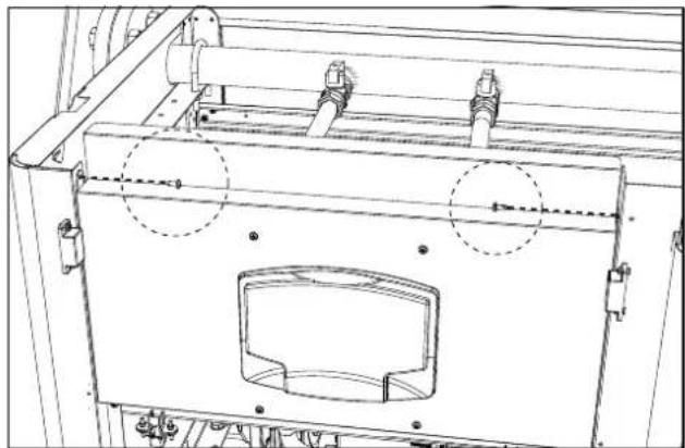
natural_image
Technical line drawing of a mechanical assembly with no visible text or symbolswygląd 5 6

natural_image
Technical line drawing of an industrial machine with internal components and directional arrows indicating flow or movement (no text or symbols present)wygląd 5 5
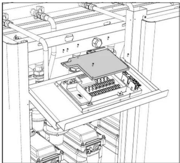
natural_image
Technical line drawing of an industrial machine with internal components and piping (no text or symbols)wygląd 5 7

natural_image
Technical line drawing of a mechanical device with cylindrical components and mounting flanges (no text or symbols)fig. 59
natural_image
Line drawing of a rectangular industrial machine with cylindrical components and wheels, no text or symbols presentfig. 60
natural_image
Technical line drawing of a mechanical device with cylindrical components and mounting flanges (no text or symbols)fig. 61

natural_image
Technical line drawing of a mechanical assembly with multiple components and mounting feet (no text or symbols)natural_image
Technical line drawing of a mechanical assembly with labeled components (no text or symbols beyond labels)natural_image
Technical line drawing of a mechanical pump assembly with mounting flanges and a labeled component 'F' (no text or symbols beyond label)wygląd67
wygląd68
wygląd71
wygląd72
natural_image
Technical line drawing of industrial piping and valves with a black arrow indicating direction (no text or symbols)natural_image
Technical line drawing of a mechanical assembly with no visible text or symbolsnatural_image
Technical line drawing of a mechanical assembly with no visible text or symbolsnatural_image
Line drawing of a mechanical device with open lid, flanges, and internal components (no text or symbols)
natural_image
Technical line drawing of a mechanical assembly with no visible text or symbolsfig. 87
natural_image
Technical line drawing of an industrial machine with internal components and mounting brackets (no text or symbols)fig. 88
Konserwacja modułów
natural_image
Mechanical diagram showing two configurations of a valve assembly with tubing and a pipe, no text or symbols present.wygląd 9 0
3.4 Usuwanie usterek
Diagnostyka
II2HM3P (IT) II2H3P (ES) II2H3P (RO) II2E3P (PL) II2EK3P (NL) I2Hs (HU)
MODEL: MACH 150 - (OMCMFAWA)
- Read the warnings in this instruction booklet carefully since they provide important information on safe installation, use and maintenance.
- This instruction booklet is an integral and essential part of the product and must be kept with care by the user for future reference.
- If the unit is sold or transferred to another owner or if it is to be moved, always make sure the booklet stays with the boiler so that it can be consulted by the new owner and/or installer.
- Installation and maintenance must be carried out by professionally qualified personnel, according to current regulations and the manufacturer's instructions.
- Incorrect installation or inadequate maintenance can result in damage or injury. The manufacturer declines any liability for damage caused by errors in installation and use or by failure to follow the instructions provided.
- Before carrying out any cleaning or maintenance operation, disconnect the unit from the power supply using the system switch and/or the special cut-off devices.
-
In case of a fault and/or poor operation, deactivate the unit and do not try to repair it or directly intervene. Contact professionally qualified personnel. Any repair/replacement of the products must only be carried out by qualified personnel using genuine parts. Failure to comply with the above can compromise the safety of the unit.
-
Periodic maintenance performed by qualified personnel is essential in order to ensure proper operation of the unit.
- This unit must only be used for its intended purpose. Any other use is deemed improper and therefore hazardous.
• After unpacking, check the good condition of the contents. The packing materials are potentially hazardous and must not be left within the reach of children. - The unit can be used by children aged at least 8 years and by persons with reduced physical, sensory or mental capabilities, or lacking experience or the necessary knowledge, only if under supervision or they have received instructions on its safe use and the related risks. Children must not play with the unit. Cleaning and maintenance intended to be done by the user can be carried out by children aged at least 8 years only if under supervision.
- In case of doubt, do not use the unit. Contact the supplier.
- The unit and its accessories must be appropriately disposed of in compliance with current regulations.
- The images given in this manual are a simplified representation of the product. In this representation there may be slight and insignificant differences with respect to the product supplied.
| This symbol indicates “CAUTION” and is placed next to all safety warnings. Strictly follow these instructions in order to avoid danger and damage to persons, animals and things | |
| This symbols calls attention to a note or important notice. | |
| This symbol, which is used on the product, packaging or documents, means that at the end of its useful life, this product must not be collected, recycled or disposed of together with domestic waste.Improper management of electric or electronic waste can lead to the leakage of hazardous substances contained in the product. For the purpose of preventing damage to health or the environment, users are kindly asked to separate this equipment from other types of waste and to ask for it to be dealt with by the municipal waste service or dealer under the conditions and according to the methods set down in national and international laws transposing the Directive 2012/19/EU.Separate waste collection and recycling of unused equipment helps to save natural resources and to guarantee that this waste is processed in a manner that is safe for health and the environment.For more information about how to collect electric and electronic equipment and appliances, please contact your local Council or Public Authority competent to issue the relevant permits. |

The CE marking certifies that the products meet the essential requirements of the relevant directives in force.
The declaration of conformity may be requested from the manufacturer.
COUNTRIES OF DESTINATION: IT - ES - RO - PL - NL - HU
1 Operating instructions .... 294
1.1 Introduction....294
1.2 Control panel 294
1.3 Lighting and shutdown 298
1.4 Adjustments....299
2 Installation....308
2.1 General Instructions ....308
2.2 Place of installation 308
2.3 Plumbing connections 310
2.4 Gas connection 322
2.5 Electrical connections....323
2.6 Flue connection 325
2.7 Condensate drain connection....327
3 Service and maintenance.... 328
3.1 Adjustments....328
3.2 Commissioning....337
3.3 Maintenance 337
3.4 Troubleshooting....341
4 Technical data and characteristics 343
4.1 Dimensions and connections ...... 344
4.2 Main components 346
4.3 Hydraulic circuit 347
4.4 Technical data table 348
4.5 ErP tables....351
4.6 Wiring diagrams 358
1. Operating instructions
1.1 Introduction
Dear Customer,
Thank you for choosing MACH, a floor-standing boiler FERROLI featuring advanced design, cutting-edge technology, high reliability and quality construction. Please read this manual carefully, as it provides important information on safe installation, use and maintenance.
MACH is a very high efficiency and low emissions premix condensing heat generator, running on natural gas or LPG. Each MACH generator internally consists of several independent aluminum thermal modules (from 2 to 8), connected in parallel and managed by a single microprocessor control system. Each thermal module inside the MACH has its own modulating premix burner and its own circulating pump.
1.2 Control panel

fig. 1 - Control panel
Legend
1 = Contextual button 1
8 = Automatic/Manual Heating/DHW button
2 = Contextual button 2
9 = Summer/Winter mode selection button
3 = Contextual button 3
10 = Economy/Comfort/Copy mode selection button
4 = Dot matrix display (example - main screen) 11 = Menu exit button
5 = Menu navigation button 12 = Main menu button
6 = Confirm/menu access button 13 = Home button (back to main screen)
7 = Menu navigation button 14 = Main switch
Contextual button
The contextual buttons (details 1, 2, 3 - fig. 1) are grey, with no screen print, and take on a different meaning depending on the menu selected. It is essential to observe the indication provided by the display (icons and text). In fig. 1 for example, using the contextual button 2 (detail 2 - fig. 1) it is possible access unit information such as: temperature of sensors, work power, etc.
Direct buttons
The direct buttons (details 8, 9, 10 - fig. 1) always have the same function.
Menu/navigation buttons
The menu/navigation buttons (details 5, 6, 7, 11, 12, 13 - fig. 1) are used to navigate among the various menus implemented in the control panel.
Menu structure
From the Home page, press the main Menu button (detail 12 - fig. 1).

fig. 2
Access the "User" menu by pressing contextual button 1 (detail 1 - fig. 1). Then use the "menu navigation" buttons to access the different levels described in the following table.
| USER MENU | |||
| HEATING | |||
 Adjustment Temp Adjustment Temp | See fig. 14 | ||
| [KZHS] Reduction Adjustment Temp | See fig. 15 | ||
[BX2A]Sliding Temperature | Curva1 | See fig. 29 | |
| Offset1 | See fig. 30 | ||
| Heating Off External Temp | See page 306 | ||
| Curve2 | / | ||
| Offset2 | / | ||
 Time Program Time Program | See “Time programming” on page 301 | ||
| ESTIC HOT WATER | |||
 _ Adjustment Temp _ Adjustment Temp | See fig. 16 | ||
 Reduction Adjustment Temp Reduction Adjustment Temp | See fig. 17 | ||
| Legionella | See “Legionella programming (with optional hot water tank installed)” on page 304 | ||
 Time Program Time Program | See “Time programming” on page 301 | ||
| VACATION FUNCTION | |||
| [ZZWY] | See “Holiday Function” on page 304 | ||
| MAINTENANCE | |||
| Test Mode | TEST Test Mode | See page 330 | |
| Gas Type Selection | See fig. 70 | ||
| Test Cascade Test Mode | See fig. 82 | ||
| Service Information | See “Service Information” on page 305 | ||
| Service Intervention Date | See “Service Intervention Date” on page 304 | ||
| SETTINGS | |||
| Language | See fig. 9 | ||
| Unit of measure | / | ||
| Date setting | See fig. 10 | ||
| Time setting | See fig. 11 | ||
| MAINTENANCE | |||
| Test Mode | TEST Test Mode | See page 330 | |
| Gas Type Selection | See fig. 70 | ||
| Test Cascade Test Mode | See fig. 82 | ||
| Service Information | See “Service Information” on page 305 | ||
| Service Intervention Date | See “Service Intervention Date” on page 304 | ||
| SETTINGS | |||
| Language | See fig. 9 | ||
| Unit of measure | / | ||
| Date setting | See fig. 10 | ||
| Time setting | See fig. 11 | ||
Indication during operation
Heating
A heating request (generated by Room Thermostat or Remote Timer Control or 0-10 Vdc signal is indicated by activation of the circulating pump and by the hot air above the radiator (fig. 3).
"Heating only/Double circulating pump" configuration

fig. 3
"Circulating pump and 3-way valve" configuration

fig. 4
DHW circuit (with optional hot water tank installed)
A hot water tank heating request is indicated by activation of the droplet under the faucet (fig. 5 and fig. 6).
"Double circulating pump" configuration

fig. 5
"Circulating pump and 3-way valve" configuration

fig. 6
Exclude hot water tank (economy)
Hot water tank temperature maintaining/heating can be excluded by the user. If excluded, domestic hot water will not be delivered. The hot water tank can be deactivated by the user (ECO mode) by pressing the eco/comfort button (detail 10 - fig. 1). In ECO mode the display activates the symbol ☒ To activate COMFORT mode, press the eco/comfort button (detail 10 - fig. 1) again.

fig. 7- Economy
Information
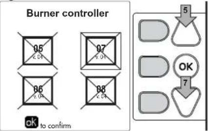
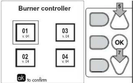
From the main screen (Home - detail A of fig. 8), press contextual button 2. Access the screen for choosing the module with information to view.
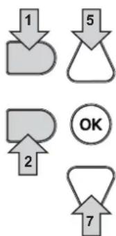
Select the module using buttons 5 and 7 (detail B and C of fig. 8) and then press OK.
A

B
C

flowchart
graph TD
    A["05\n0.01"] --> B["OK"]
    C["06\n0.34"] --> D["OK"]
    E["07\n0.01"] --> F["OK"]
    G["08\n0.01"] --> H["OK"]
    I["5"] --> J["OK"]
    K["ok to confirm"] --> L["OK to confirm"]
fig. 8
Then use the "Menu Navigation" buttons to display the following values:
| 1 Heating demand | OT - OpenTherm control request | |
| TA - Room thermostat request | ||
| 0-10Vdc - 0-10Vdc signal request | ||
| TA2 - Second room thermostat request | ||
| 2 Heating circulating pump ON/OFF | ||
| 3 Heating 3-way valve ON/OFF | ||
| 4 DHW 3-way valve ON/OFF | ||
| 5 Standby time ON/OFF | ||
| 6 T Delta protection ON/OFF | ||
| 7 Flame Supervisor ON/OFF | ||
| 8 Heating sensor 1 (Flow) °C | ||
| 9 Heating sensor 2 (Safety) °C | ||
| 10 Return sensor | °C | |
| 11 DHW sensor | °C | |
| 12 External probe | °C | |
| 13 Fume sensor °C | ||
| 14 Cascade heating sensor | °C | |
| 15 Fan frequency | Hz | |
| 16 Burner load | % | |
| 17 System water pressure | 1.4bar = ON, 0.0 bar = OFF | |
| 18 Modulating circulating pump | % | |
| 19 Cascade modulating circulating pump | % | |
| 20 Ionization current uA | ||
| 21 Input 0-10Vdc | Vdc | |
| 22 Heating adjustment temperature | Setpoint (°C) | |
| 23 Power level adjustment 0-10Vdc | Setpoint (%) | |
1.3 Lighting and shutdown
Boiler lighting
Press the On/Off button (detail 14 - fig. 1).


X = 2 - MACH 150
X = 3 - MACH 225
X = 4 - MACH 300
X = 5 - MACH 370
X = 6 - MACH 450
X = 7 - MACH 520
X = 8 - MACH 600

fig. 9- Boiler ignition (X indicates the number of burners)
By pressing contextual button 1 it is possible to choose the desired language and confirm it with the "OK" button.
By pressing contextual button 3 it is possible to interrupt the FH mode.
If neither of the two choices described above is made, continue as follows.
• For the following 300 seconds the display will show FH which identifies the heating system air venting cycle.
- The display also shows the firmware version of the cards.
- Open the gas cock ahead of the boiler.
- When the message FH disappears, the boiler is ready to operate automatically in case of a room thermostat request.
Settings
Contrast adjustment
To adjust the display contrast, press the contextual button 2 and the OK button together. Then press the button ref. 5 of fig. 1 to increase the contrast or the button ref. 7 of fig. 1 to decrease it.
Date and Time Adjustment
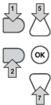
Reach the screen shown in fig. 10, navigating in the menu and following the path "USER MENU Settings" "Date Setting". Press navigation buttons 5 and 7 to select the value and modify it with contextual buttons 1 and 2. Confirm with the OK button.

flowchart
graph TD
    A["1"] --> B["2"]
    C["5"] --> D["3"]
    E["7"] --> F["4"]
    G["OK"] --> H["OK"]
fig. 10- Date Adjustment
Reach the screen shown in fig. 11, navigating in the menu and following the path "USER MENU Settings" Time Setting". Press navigation buttons 5 and 7 to select the value and modify it with contextual buttons 1 and 2. Confirm with the OK button.

fig. 11- Time Adjustment
Boiler shutdown
From the main screen/Home, press the contextual button and confirm with the button. OK
When the boiler is turned off, the PCB is still powered.
Domestic hot water (with optional hot water tank installed) and heating operation are disabled. The frost protection system remains on.
To relight the boiler, press the contextual button again
The boiler will be immediately ready to operate whenever domestic hot water is drawn (with optional hot water tank installed) or in case of a room thermostat request.
To completely disconnect the unit from the power supply, press the button detail 14 fig. 1.

fig. 12- Turning the boiler off

The frost protection system does not work when the power and/or gas to the unit are turned off. To avoid damage caused by freezing during long shutdowns in winter, it is advisable to drain all water from the boiler, the DHW circuit and the heating system water; or drain just the DHW circuit and add a suitable antifreeze to the heating system, as prescribed in sec. 2.3.
1.4 Adjustments
Summer/Winter Switchover
Press the button (detail 9 - fig. 1) for 1 second.
The display activates the Summer symbol. The heating function is deactivated while possible DHW production remains active (with optional external hot water tank). The frost protection system remains on.
To deactivate Summer mode, press the button (detail 9 - fig. 1) again for 1 second.

fig. 13- Summer
Heating temperature adjustment
Access the "Adjustment Temp" menu to vary the temperature from a minimum of 20 °C to a maximum of 90 °C. Confirm with the OK button.

The boiler comes with the time program not activated. Therefore, if requested, this is the setpoint value.


fig. 14
Heating temperature reduction
Access the "Reduction Adjustment Temp" menu to vary the temperature from a minimum of 0°C to a maximum of 50°. Confirm with the OK button.

This parameter is used only if time programming is activated. See "Time programming" on page 301


fig. 15
DHW temperature adjustment (with optional hot water tank installed)
Access the "Adjustment Temp" menu to vary the temperature from a minimum of 10^ to a maximum of 65^ . Confirm with the OK button.

The boiler comes with the time program not activated. Therefore, if requested, this is the setpoint value.


fig. 16
DHW temperature reduction (with optional hot water tank installed)
Access the "Reduction Adjustment Temp" menu to vary the temperature from a minimum of 0°C to a maximum of 50°C. Confirm with the OK button.

This parameter is used only if time programming is activated. See "Time programming" on page 301


fig. 17
Time programming
Time programming is done in the same way both for heating and for DHW; the two programs are independent.
To program Heating, access the "Time Program" menu by following the path "USER MENU ➔ "HEATING" ➔ "Time Program".
To program DHW, access the "Time Program" menu by following the path "USER MENU ➔ "DOMESTIC HOT WATER" ➔ "Time Program".
Choose the type of programming to carry out and follow that described below.
Select the day (fig. 18) or the interval of days to program (fig. 19) and confirm with the OK button.


fig. 18 fig. 19
The program is weekly: this means that 6 independent time bands can be set for each day of the week (fig. 20); 4 options can be chosen for each time band:
- ON. In case of a Heating/DHW request, the boiler works at the set Heating/DHW Adjustment Temperature (fig. 14/fig. 16).
- In case of a Heating/DHW request, the boiler works at the Reduced Adjustment Temperature. The Reduced temperature is obtained by subtracting the Reduction Adjustment Temperature (fig. 15/fig. 17) value from the set Heating/DHW Adjustment Temperature (fig. 14/fig. 16).
• OFF. In case of a heating/DHW request, the boiler will not activate the Heating/DHW mode. - -- : -- OFF. Time band disabled.

The boiler comes with the time program not activated. In fact, every day will be programmed from 00:00 to 24:00h in ON mode (fig. 20).
First, set the start time of the first time band (fig. 20) using contextual buttons 1 and 2.
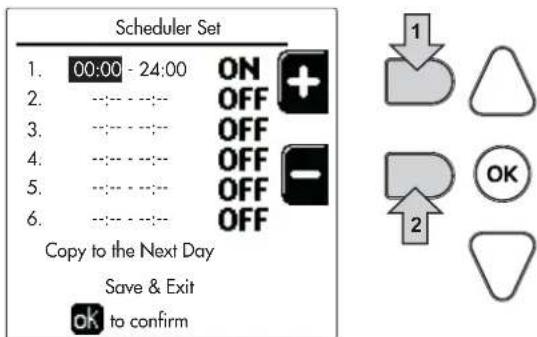
fig. 20
Press navigation button 7 to go to the end time of the first time band (fig. 21) and set it to the desired value using contextual buttons 1 and 2.

fig. 21

Press navigation button 7 and use contextual buttons 1 and 2 to set the work mode during the first time band (fig. 22)
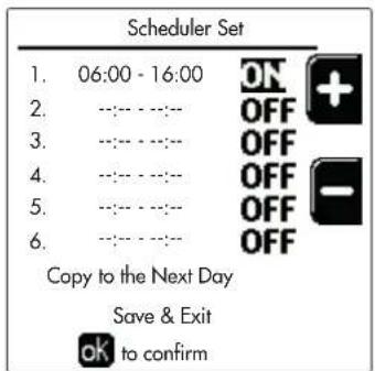
fig. 22
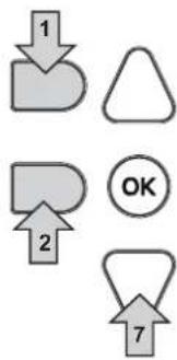
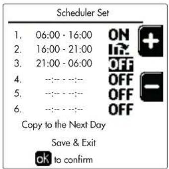
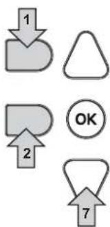
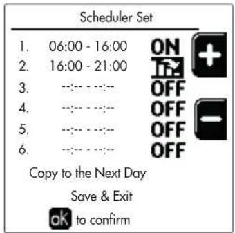
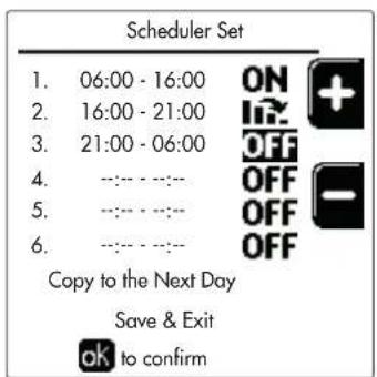
Then, press navigation button 7 to set (if necessary) the subsequent time bands (fig. 23, fig. 24 and fig. 25).

fig. 23 fig. 24

flowchart
graph TD
    A["1"] --> B["2"]
    C["△"] --> D["OK"]
    E["7"] --> F["△"]
flowchart
graph TD
    A["5"] --> B["6"]
    B --> C["OK"]
    C --> D["7"]
fig. 25
When the day has been programmed, press the OK button; the item "Save & Exit" will automatically be selected (fig. 26). Use navigation buttons 5 and 7 to modify the previous settings or press OK to confirm: in this case the display will return to showing the day (fig. 18) or the interval of days to be programmed (fig. 19). The same procedure can then be followed to complete the desired weekly program.
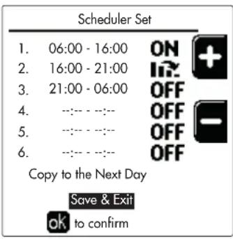
fig. 26
To program the following day in the same way, select "Copy to next day" and press OK to confirm (fig. 26).

To restore the time program to the factory values, press contextual button 3 in the Time Program menu (fig. 27) and confirm with OK.

fig. 27

The two Heating and DHW hourly programs are independent even in case of Reset to factory value.
Legionella programming (with optional hot water tank installed)
To enable the Anti-Legionella Function it is necessary to set parameter P23, within the "TECHNICAL MENU", to ON.
To program the function it is necessary to access the "Legionella" menu via the path "USER MENU" → "DOMESTIC HOT WATER" → "Legionella".
In this menu it is possible to set the following options:
- Anti-Legionella day. Defines the day of the week during which the function will be activated. The function can only be activated once a week.
• Anti-Legionella time of day. Defines the start time of the function. - Anti-Legionella duration. Defines the duration (in minutes) of the function.
- Anti-Legionella Adjustment Temp. Defines the DHW Adjustment temperature during the function.

ATTENTION
• In ECO mode the function is not active.
- The Anti-Legionella Function will only be active if the boiler is set to "Automatic" mode" (☐) and only in the time bands set to ON or to "Reduced temperature" (☐).
Otherwise, in the time bands set to OFF, the function will not be activated, even if set.
- In vacation mode (💡) the Anti-Legionella Function is active.
- If the Anti-Legionella Function is not carried out correctly, the message shown in fig. 28 is displayed. Even in the presence of this message, the boiler will continue to operate correctly.

fig. 28- Message Anti-legionella function not completed

The temperature set via the "Anti-Legionella Adjustment Temp." menu must NOT be higher than the maximum DHW adjustment temperature set via parameter P19 within the TECHNICAL MENU.

If a circulating pump is installed in the system, for water circulation during the Anti-Legionella Function, parameter b08 must be set to 1. In this way the contact between terminals 9-10 (ref. 300 - fig. 99) closes when the function is activated.
Holiday Function
Access the "HOLIDAY FUNCTION" menu through the path "USER MENU ➕ HOLIDAY FUNCTION" to set:
- Holiday start date.
- Holiday end date.
The display can activate two types of icons:
- The Holiday function is programmed but not yet active.
- The Holiday function is in progress. The boiler will behave as if Summer mode and Economy mode were active (with optional hot water tank installed).
The frost protection and Legionella functions will remain active (if activated).
Service Intervention Date
This informs when the alert of programmed maintenance by the technician will be activated. It does not represent an alarm or a fault but just a notice. After that date, whenever the Main menu is accessed, the boiler will activate a screen indicating that programmed maintenance is due.
Service Information
This information shows the telephone number to contact in case of assistance (if programmed by the technician).
Room temperature adjustment (with optional room thermostat)
Using the room thermostat, set the temperature required in the rooms.
Room temperature adjustment (with optional remote timer control)
Using the remote timer control, set the temperature desired in the rooms. The boiler unit will set the system water according to the required room temperature. For information on the remote timer control, please refer to its user's manual.
Sliding Temperature
When the external probe (optional) is installed, the relevant external temperature symbol is activated on the control panel display. The boiler control system works with "Sliding Temperature". In this mode, the heating system temperature is regulated according to weather conditions, to ensure high comfort and energy efficiency throughout the year. In particular, as the outside temperature increases the system flow temperature decreases according to a specific "compensation curve".
With Sliding Temperature adjustment, the "Heating adjustment" temperature becomes the maximum system flow temperature. It is advisable to set a maximum value to allow system adjustment throughout its useful operating range.
The boiler must be adjusted at the time of installation by qualified personnel. The user can still make further adjustments for better comfort.
Compensation curve and curve offset
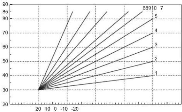
Access the Sliding Temperature menu. Adjust the desired curve from 1 to 10 according to the characteristic (fig. 31) via the parameter "Curve1" and confirm with the OK button.
By setting the curve to 0, the sliding temperature adjustment is disabled.

fig. 29- Compensation curve
Adjust the parallel offset of the curves from 20 to 60 °C (fig. 32), via the parameter "Offset1" and confirm with the OK button.

fig. 30- Parallel curve offset
If the room temperature is lower than the desired value, it is advisable to set a higher order curve and vice versa. Proceed by increasing or decreasing in steps of one and check the result in the room.
line
| x | y | |----|------| | 20 | 30 | | 10 | 40 | | 0 | 50 | | -10| 60 | | -20| 70 | | -30| 80 | | -40| 90 |fig. 31- Compensation curves

line
| x | y | |----|------| | 20 | 20 | | 10 | 85 | | 9 | 80 | | 8 | 75 | | 7 | 70 | | 6 | 65 | | 5 | 60 | | 4 | 55 | | 3 | 50 | | 2 | 45 | | 1 | 40 |
line
| x | y | |----|------| | 20 | 60 | | 10 | 70 | | 9 | 75 | | 8 | 80 | | 7 | 85 | | 6 | 90 | | 5 | 95 | | 4 | 100 | | 3 | 105 | | 2 | 110 | | 1 | 115 |fig. 32- Example of compensation parallel curve offset

This parameter is used only if the time programming has been activated. See "Time programming" on page 301
Outside Temperature Heating OFF
Access the "Out Temp Heat Off" to activate the function: between 7°C and 30°C.
If activated, this function will deactivate the heating demand whenever the temperature measured by the external probe is higher than the programmed value.
The heating demand will be reactivated as soon as the temperature measured by the external probe is lower than the programmed value.
Adjustments from remote timer control

If the boiler is connected to the Remote Timer Control (optional), the previously described adjustments are managed as described in table 1.
Table 1
| Heating temperature adjustment | Adjustment can be made from the Remote Timer Control menu and the boiler control panel. |
| DHW temperature adjustment (with optional hot water tank installed) | Adjustment can be made from the Remote Timer Control menu and the boiler control panel. |
| Summer/Winter Switchover | Summer mode has priority over a possible Remote Timer Control heating request. |
| Eco/Comfort selection (with optional hot water tank installed) | On disabling DHW from the Remote Timer Control menu, the boiler selects Economy mode. In this condition, the button detail 10 - fig. 1 on the boiler panel, is disabled. |
| By enabling DHW from the Remote Timer Control menu, the boiler selects Comfort mode. In this condition, use the button detail 10 - fig. 1 on the boiler panel to select one of the two modes. | |
| Sliding Temperature | Both the Remote Timer Control and the boiler card manage the Sliding Temperature adjustment: between the two, the Sliding Temperature of the boiler card has priority. |
System water pressure adjustment
The filling pressure with the system cold must be approx. 1.0 bar. If the system pressure falls to values below minimum, the boiler card will activate fault 37 and the number of the module (fig. 33).

Once the system pressure is restored, the boiler will activate the 300-second air venting cycle indicated on the display by FH.

fig. 33- Module 1 insufficient system pressure fault
2. Installation
2.1 General Instructions
BOILER INSTALLATION MUST ONLY BE PERFORMED BY QUALIFIED PERSONNEL, IN ACCORDANCE WITH ALL THE INSTRUCTIONS GIVEN IN THIS TECHNICAL MANUAL, THE PROVISIONS OF CURRENT LAW, THE PRESCRIPTIONS OF NATIONAL AND LOCAL STANDARDS AND THE RULES OF PROPER WORKMANSHIP.
2.2 Place of installation
Handling
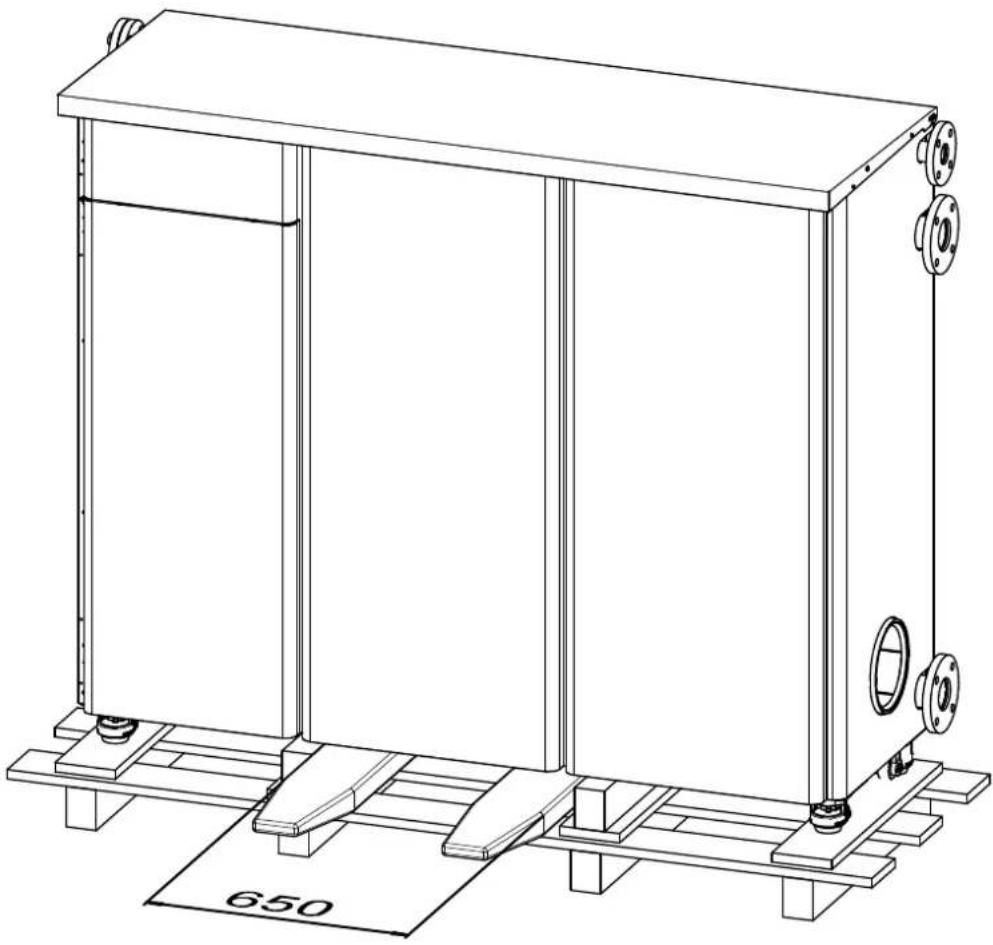
To remove the boiler from the packing base, use a forklift truck with external distance between the forks of not less than 650 mm.
natural_image
Technical line drawing of a rectangular industrial machine with mounting base and side supports (no text or symbols)Positioning
The generator must be installed in a suitable room with ventilation openings towards the outside in conformity with current regulations. If there are several burners or exhausters that can work together in the same room, the ventilation openings must be sized for simultaneous operation of all the units. The place of installation must be free of flammable materials or objects, corrosive gases, powders or volatile substances. The room must be dry and not exposed to rain, snow or frost. For positioning, leave enough space around the unit for normal maintenance operations (see fig. 34).

fig. 34- Positioning with distances to be respected
2.3 Plumbing connections
For correct operation it is necessary to install a hydraulic separator between the unit and the system as indicated in fig. 35.
A pump external to the unit must not be used in the generator hydraulic loop (1), as the circulation of heat transfer fluid in the loop (1) is ensured by the circulating pumps inside the unit and managed by its control system. An adequately sized external pump must be provided for circulation only in the system hydraulic loop (2).

flowchart
graph TD
    A["Top Component"] --> B["Valve 1"]
    B --> C["Valve 2"]
    C --> D["Valve 3"]
    D --> E["Valve 4"]
    E --> F["Valve 5"]
    F --> G["Valve 6"]
    G --> H["Valve 7"]
    H --> I["Valve 8"]
    I --> J["Valve 9"]
    J --> K["Valve 10"]
    K --> L["Valve 11"]
    L --> M["Valve 12"]
    M --> N["Valve 13"]
    N --> O["Valve 14"]
    O --> P["Valve 15"]
    P --> Q["Valve 16"]
    Q --> R["Valve 17"]
    R --> S["Valve 18"]
    S --> T["Valve 19"]
    T --> U["Valve 20"]
    U --> V["Valve 21"]
    V --> W["Valve 22"]
    W --> X["Valve 23"]
    X --> Y["Valve 24"]
    Y --> Z["Valve 25"]
fig. 35
The unit's internal circulating pumps are sized for circulation only in the generator hydraulic loop, and cannot be used for direct circulation in systems without a hydraulic separator.
The heating capacity of the unit must be previously established by calculating the building's heat requirement according to current regulations. The system must be provided with all the components for correct and regular operation. In particular, provide for all the protection and safety devices required by current regulations. They must be installed on the hot water circuit flow piping, upstream of the hydraulic separator, within a distance of not more than 0.5 m, without interposing shutoff devices. The unit is not supplied with an expansion vessel or safety valve, therefore their connection must be carried out by the installer.
The safety valve outlet must be connected to a funnel or collection pipe to prevent water spurting onto the floor in case of overpressure in the heating circuit. Otherwise, if the discharge valve cuts in and floods the room, the boiler manufacturer cannot be held liable.
Do not use the water system pipes to ground electrical appliances.
Before installation, flush all the pipes of the system thoroughly to remove any residuals or impurities that could affect proper operation of the unit. Use chemical conditioners suitable for the purpose; i.e. able to remove from the walls and bottom of the pipes and the various components of the system, sludge, metal oxides and, in low temperature systems, also biomass, with just the circulation of the water, with system hot and/or cold. The products used must not be corrosive and/or aggressive for metals and plastics and must not significantly alter the natural pH of the water.

Also, a filter must be installed on the system return piping to prevent impurities or sludge from the system clogging and damaging the heat generators.
The filter must be installed when replacing generators in existing systems. The manufacturer declines any liability for damage caused to the generator by failure to install or inadequate installation of this filter.
Make the connections to the corresponding connections according to the drawing in fig. 36.
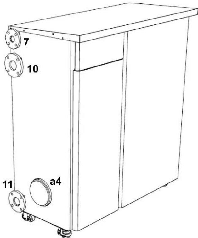
fig. 36
Table 2- SIZE OF CONNECTIONS
| 10 - System flow | DN65 flanged |
| 11 - System return | DN65 flanged |
| 7 - Gas inlet | DN40 flanged |
| a4 - Flue connection ∅200 |
System water characteristics
Before installing the MACH generator, the new or existing system must be properly cleaned in order to eliminate installation residues, solvents, sludge and contaminants in general that may compromise the effectiveness of the protective conditioning treatments. Use neutral cleaning products that do not attack metals, rubber and plastic parts of the generator/system. Empty, wash and recharge the system in compliance with the following instructions. A dirty system will not guarantee the life of the generator over time, even with the use of protective conditioners.

MACH boilers are suitable for installation in heating systems with non-significant entry of oxygen (ref. systems "case I" EN14868). A physical separator (e.g. plate heat exchanger) must be provided in systems with continuous entry of oxygen (e.g. underfloor systems without anti-diffusion pipes or open vessel), or frequent (frequent water replenishment).
The water in a heating system must be treated in compliance with the laws and regulations in force, have the characteristics required by UNI 8065, and comply with the provisions of EN14868 (protection of metallic materials against corrosion).
The filling water (first filling and subsequent replenishments) must be potable, clear, with hardness under the values indicated in the table below and treated and conditioned with chemical conditioners declared suitable by the maker (see following list), in order to prevent encrustations, corrosive or aggressive phenomena on the metals and plastics of the generator and system, the formation of gas, and the proliferation of bacterial or microbial masses in low temperature systems.
The water contained in the system, as well as the replenishment water, must be checked periodically (at every start-up of the system, after any non-scheduled intervention such as, for example, replacement of the generator or other system
components, as well as at least once a year during mandatory routine maintenance operations as required by UNI 8065). The water must have a clear appearance and respect the limits given in the following table.
| EXISTING SYSTEM NEW SYSTEM | ||
| WATER PARAMETER | ||
| Total filling water hardness (°f) <10 <10 | ||
| Total system water hardness (°f) <15 <10 | ||
| PH 7 < Ph < 8.5 | ||
| Copper Cu (mg/l) Cu < 0.5 mg/l | ||
| Iron Fe (mg/l) Fe < 0.5 mg/l | ||
| Chlorides (mg/l) Cl < 50 mg/l | ||
| Conductivity (μS/cm) < 600 μS/cm* | ||
| Sulfates < 100 mg/l | ||
| Nitrates < 100 mg/l | ||
* In the presence of conditioners, the limit increases to 1200 μS/cm.
In case of differing values or difficult verification of values with conventional analysis/testing procedures, contact the company for additional evaluations. The conditions of the feed water to be treated can vary even significantly depending on the geographical areas where the systems are located.
Chemical conditioners deoxygenating, anti-scaling, corrosion inhibiting, anti-bacterial, anti-algae, frost protection, PH correction products, etc., must also be suitable for the materials of the generator and system. They must be put in the system respecting the quantity indicated by the supplier of the chemical product and verified in their concentration.

A chemical conditioner in insufficient concentration will not be able to ensure the required protection.
Always check the product concentration each time it is added and cyclically, at least once a year, using qualified technical personnel such as our authorized technical assistance network.
Table 3- Chemical conditioners declared suitable and available at our network of Authorized Technical Assistance Centers
| Description | Sentinel type alternative products | |
| LIFE PLUS/B - MOLY - MOLY K | Molybdenum-based corrosion inhibitor | X100 |
| LIFE DUE | Noise reduction/anti-scaling maintenance | X200 |
| BIO KILL | Biocidal anti-algae | X700 |
| PROGLI | Propylene frost protection | X500 |
| Products with equivalent characteristics may be used | ||
The unit is equipped with a frost protection system that activates the boiler in heating mode when the flow water temperature falls below 5^ C. The device is not active if the electrical and/or gas supply to the unit is disconnected. If necessary, to protect the system use a suitable antifreeze liquid that meets the above requirements and provided for by UNI 8065.
To ensure the reliability and correct operation of the boilers, always install a mechanical filter in the loading circuit and, in the system, a dirt separator (possibly magnetic) and a deaerator as required by the UNI 8065 as well as a volumetric meter on the system replenishment line.

Failure to comply with the provisions of this paragraph, "System water features", will involve non-recognition of the warranty and damage due to such shortcomings.
Hydraulic circuit examples
In the examples described below, the checking/change of some parameters may be required.
To do this it is necessary to access the Technical menu.
From the Home page, press the main Menu button (detail 12 - fig. 1).
Access the "Technical" menu by pressing contextual button 2 (detail 2 - fig. 1).

fig. 37
Enter the code "4 1 8" with contextual buttons 1 and 2. Confirm each number with the OK button.

fig. 38
Access the Parameters menu by pressing the OK button.

fig. 39
Access the "Configuration Menu" or "System Type Menu" according to the parameter to be modified as given in each hydraulic circuit example.

fig. 40
Two direct heating circuits
- Schematic diagram

flowchart
graph TD
    A["138"] --> B["M"]
    B --> C["I*"]
    C --> D["Valve"]
    D --> E["Sensor"]
    E --> F["Valve"]
    F --> G["Sensor"]
    G --> H["Valve"]
    H --> I["Sensor"]
    I --> J["Valve"]
    J --> K["Sensor"]
    K --> L["Valve"]
    L --> M["Sensor"]
    M --> N["Valve"]
    N --> O["Sensor"]
    O --> P["Valve"]
    P --> Q["Sensor"]
    Q --> R["Valve"]
    R --> S["Sensor"]
    S --> T["Valve"]
    T --> U["Sensor"]
    U --> V["Valve"]
    V --> W["Sensor"]
    W --> X["Valve"]
    X --> Y["Sensor"]
    Y --> Z["Valve"]
    Z --> AA["Sensor"]
    AA --> AB["Valve"]
    AB --> AC["Sensor"]
    AC --> AD["Valve"]
    AD --> AE["Sensor"]
    AE --> AF["Valve"]
    AF --> AG["Sensor"]
    AG --> AH["Valve"]
    AH --> AI["Sensor"]
    AI --> AJ["Valve"]
    AJ --> AK["Sensor"]
    AK --> AL["Valve"]
    AL --> AM["Sensor"]
    AM --> AN["Valve"]
    AN --> AO["Sensor"]
    AO --> AP["Valve"]
    AP --> AQ["Sensor"]
    AQ --> AR["Valve"]
    AR --> AS["Sensor"]
    AS --> AT["Valve"]
    AT --> AU["Sensor"]
    AU --> AV["Valve"]
    AV --> AW["Sensor"]
    AW --> AX["Valve"]
    AX --> AY["Sensor"]
    AY --> AZ["Valve"]
    AZ --> BA["Sensor"]
    BA --> BB["Valve"]
    BB --> BC["Sensor"]
    BC --> BD["Valve"]
    BD --> BE["Sensor"]
    BE --> BF["Valve"]
    BF --> BG["Sensor"]
    BG --> BH["Valve"]
    BH --> BI["Sensor"]
    BI --> BJ["Valve"]
    BJ --> BK["Sensor"]
    BK --> BL["Valve"]
    BL --> BM["Sensor"]
    BM --> BN["Valve"]
    BN --> BO["Sensor"]
    BO --> BP["Valve"]
    BP --> BQ["Sensor"]
    BQ --> BR["Valve"]
    BR --> BS["Sensor"]
    BS --> BT["Valve"]
    BT --> BU["Sensor"]
    BU --> BV["Valve"]
fig. 41
- Electrical connections
After installation, carry out the necessary electrical connections as shown in the wiring diagram.
Then configure the controller as described in the specific section.

fig. 42
Legend (fig. 41 and fig. 42)
72 1st zone (direct) room thermostat
72b 2nd zone (direct) room thermostat
138 External probe
307 1st zone (direct) circulating pump
306 2nd zone (direct) circulating pump
to 1st zone (direct)
b 2nd zone (direct)
M Flow
R Return
I* ISPESL safety devices
(When required. Not supplied)
To manage the sliding temperature it is necessary to purchase the external probe accessory code 013018X0
- Parameters
Each system requires a different parameterization. Follow the access procedure given below.
"System Type Menu"
Change parameter P.01 of the "System Type Menu" to 4.
- Optional features
In addition to the electrical connections of the previous figure (necessary for this system configuration) there are options that do not require settings.
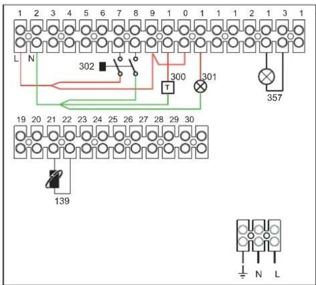
fig. 43
Legend
139 Remote control: it can be installed instead of 72 to manage the request of the 1st zone (direct)
300 Burner on indication (voltage-free contact output): the example shows the connection of a 230 Vac hour meter
301 Fault indication (voltage-free contact output): the example shows the connection of a 230Vac lamp
302 Remote reset input (230Vac): the example shows the connection of a double-pole switch at 230Vac, allowing the resetting of a block type fault
357 Fault indication (230Vac): the example shows the connection of a 230Vac lamp
One direct heating circuit and one DHW circuit with circulating pump
- Schematic diagram
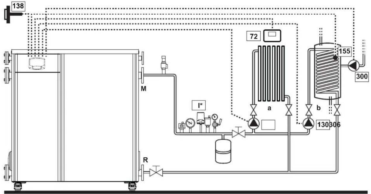
flowchart
graph TD
    A["138"] --> B["M"]
    B --> C["R"]
    C --> D["I*"]
    D --> E["Valve"]
    E --> F["72"]
    F --> G["a"]
    G --> H["155"]
    H --> I["b"]
    I --> J["300"]
    J --> K["130 306"]
    K --> L["Valve"]
    style A fill:#f9f,stroke:#333
    style B fill:#ccf,stroke:#333
    style C fill:#cfc,stroke:#333
    style D fill:#fcc,stroke:#333
    style E fill:#cff,stroke:#333
    style F fill:#ffc,stroke:#333
    style G fill:#cfc,stroke:#333
    style H fill:#fcc,stroke:#333
    style I fill:#cfc,stroke:#333
    style J fill:#fcc,stroke:#333
    style K fill:#cfc,stroke:#333
fig. 44
- Electrical connections
After installation, carry out the necessary electrical connections as shown in the wiring diagram. Then configure the controller as described in the specific section.

fig. 45
Legend (fig. 44 and fig. 45)
72 1st zone (direct) room thermostat
130 Hot water tank circulating pump
138 External probe
155 Hot water tank probe
300 Anti-Legionella circulating pump
306 1st zone (direct) circulating pump
to 1st zone (direct)
b Hot water tank circuit
M Flow
R Return
I* ISPESL safety devices
(When required - not supplied)
To manage the sliding temperature it is necessary to purchase the external probe accessory code 013018X0
If a hot water tank probe (not supplied) is used, it is necessary to purchase the NTC probe accessory code 1KWMA11W (2 mt.) or code 043005X0 (5 mt.)
If a hot water tank thermostat (not supplied) is used, it is necessary to purchase the accessory kit code 013017X0 (to be connected in place of the Hot Water Tank Probe)
- Parameters
Each system requires a different parameterization. Follow the access procedure given below.
"Configuration - Parameters Menu"
Check/Change parameter b02 of the "Transparent Parameters Menu" to 8.
Check/Change parameter b08 of the "Transparent Parameters Menu" to 1.
Check/Change parameter b04, b05 and b06 of the "Transparent Parameter Menu" according to the values given in the table "Configuration - Parameters Menu" on page 334.
- Optional features
In addition to the electrical connections of the previous figure (necessary for this system configuration) there are options that do not require settings.

fig. 46
Legend
139 Remote control: it can be installed instead of 72 to manage the request of the 1st zone (direct)
301 Fault indication (voltage-free contact output): the example shows the connection of a 230Vac lamp
302 Remote reset input (230Vac): the example shows the connection of a double-pole switch at 230Vac, allowing the resetting of a block type fault
357 Fault indication (230Vac): the example shows the connection of a 230Vac lamp
A direct heating circuit and a DHW circuit with diverter valve (3-wire)
- Schematic diagram
Use diverter valves with 3 wires:
- 230V OPENING PHASE
- 230V CLOSING PHASE
- NEUTRAL
with switching times (from all closed to all open) of not more than 90 seconds.
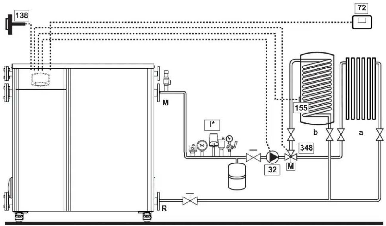
flowchart
graph TD
    A["138"] --> B["Process Unit"]
    B --> C["M"]
    C --> D["I*"]
    D --> E["Valve"]
    E --> F["Valve"]
    F --> G["Valve"]
    G --> H["Valve"]
    H --> I["Valve"]
    I --> J["Valve"]
    J --> K["Valve"]
    K --> L["Valve"]
    L --> M["Valve"]
    M --> N["Valve"]
    N --> O["Valve"]
    O --> P["Valve"]
    P --> Q["Valve"]
    Q --> R["Valve"]
    R --> S["Valve"]
    S --> T["Valve"]
    T --> U["Valve"]
    U --> V["Valve"]
    V --> W["Valve"]
    W --> X["Valve"]
    X --> Y["Valve"]
    Y --> Z["Valve"]
    Z --> AA["Valve"]
    AA --> AB["Valve"]
    AB --> AC["Valve"]
    AC --> AD["Valve"]
    AD --> AE["Valve"]
    AE --> AF["Valve"]
    AF --> AG["Valve"]
    AG --> AH["Valve"]
    AH --> AI["Valve"]
    AI --> AJ["Valve"]
    AJ --> AK["Valve"]
    AK --> AL["Valve"]
    AL --> AM["Valve"]
    AM --> AN["Valve"]
    AN --> AO["Valve"]
    AO --> AP["Valve"]
    AP --> AQ["Valve"]
    AQ --> AR["Valve"]
    AR --> AS["Valve"]
    AS --> AT["Valve"]
    AT --> AU["Valve"]
    AU --> AV["Valve"]
    AV --> AW["Valve"]
    AW --> AX["Valve"]
    AX --> AY["Valve"]
fig. 47
Legend (fig. 47 and fig. 48)
32 Heating circulating pump
72 1st zone (direct) room thermostat
138 External probe
155 Hot water tank probe
348 3-way valve (3-wire)
$$ A = O P E N I N G P H A S E $$
$$ B = N E U T R A L $$
$$ C = C L O S I N G P H A S E $$
to 1st zone (direct)
b Hot water tank circuit
M Flow
R Return
K1 - K2coil 230 Vac, <2.2 VA
$$ \text { contact } 2 3 0 \mathrm{Vac}, > 8 \mathrm{A} $$
I* ISPESL safety devices
$$ (\text { When required - not supplied }) $$
- Electrical connections
After installation, carry out the necessary electrical connections as shown in the wiring diagram.
Then configure the controller as described in the specific section.

To avoid damaging the board, it is advisable to use external relays to control the 3-way valve, as indicated in fig. 48.
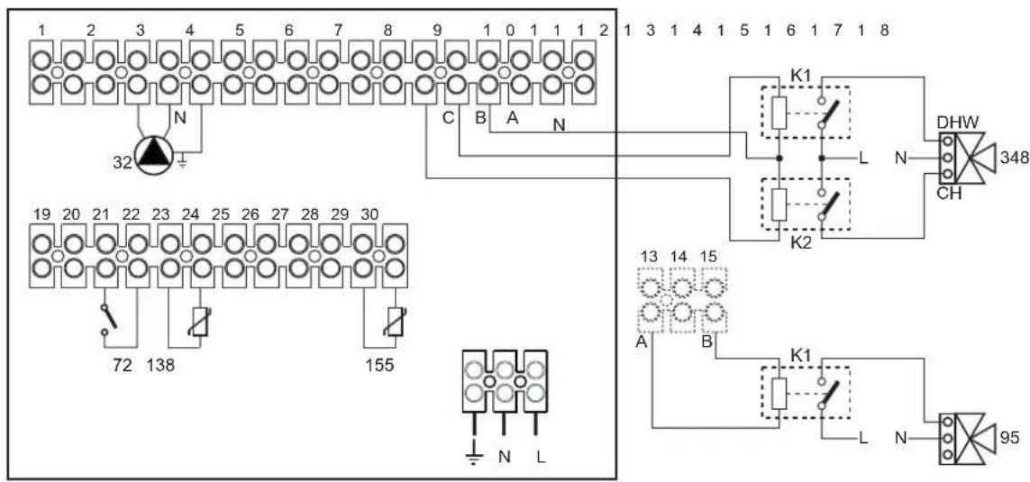
fig. 48
To manage the sliding temperature it is necessary to purchase the external probe accessory code 013018X0
If a hot water tank probe (not supplied) is used, it is necessary to purchase the NTC probe accessory code 1KWMA11W (2 mt.) or code 043005X0 (5 mt.)
If a hot water tank thermostat (not supplied) is used, it is necessary to purchase the accessory kit code 013017X0 (to be connected in place of the Hot Water Tank Probe)
- Parameters
Each system requires a different parameterization. Follow the access procedure given below.
"Configuration - Parameters Menu"
Check/Change parameter b02 of the "Configuration - Parameters Menu" to 9.
Check/Change parameter b04, b05 and b06 of the "Configuration - Parameters Menu" according to the values given in the table "Configuration - Parameters Menu" on page 334.
- Optional features
In addition to the electrical connections of the previous figure (necessary for this system configuration) there are options that do not require settings.

fig. 49
Legend
139 Remote control: it can be installed instead of 72 to manage the request of the 1st zone (direct)
300 Burner on indication (voltage-free contact output): the example shows the connection of a 230Vac hour meter
301 Fault indication (voltage-free contact output): the example shows the connection of a 230Vac lamp
302 Remote reset input (230Vac): the example shows the connection of a double-pole switch at 230Vac, allowing the resetting of a block type fault
357 Fault indication (230Vac): the example shows the connection of a 230Vac lamp
Two mixed heating circuits, one direct heating circuit and one DHW circuit with circulating pump
- Schematic diagram
The FZ4B zone control board can manage different types of systems. An example is given.
Use diverter valves with 3 wires: OPENING PHASE 230V - CLOSING PHASE 230V - NEUTRAL, with switching times (from fully closed to fully open) not exceeding 180 seconds
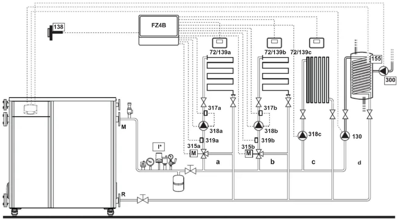
flowchart
graph TD
    A["138"] --> B["FZ4B"]
    B --> C["72/139a"]
    B --> D["72/139b"]
    B --> E["72/139c"]
    C --> F["317a"]
    D --> G["317b"]
    E --> H["318a"]
    E --> I["318b"]
    E --> J["318c"]
    F --> K["315a"]
    G --> L["315b"]
    H --> M["319a"]
    I --> N["319b"]
    J --> O["318c"]
    K --> P["a"]
    L --> Q["b"]
    M --> R["c"]
    N --> S["d"]
    O --> T["d"]
    U["I*"] --> V["M"]
    W["R"] --> X["M"]
    Y["300"] --> Z["155"]
fig. 50
Legend (fig. 50 and fig. 51)
72a 1st zone (mixed) room thermostat
72b 2nd zone (mixed) room thermostat
72c 3rd zone (direct) room thermostat
130 Hot water tank circulating pump
138 External probe
139a 1st zone (mixed) Remote Timer Control
139b 2nd zone (mixed) Remote Timer Control
139c 3rd zone (direct) Remote Timer Control
155 Hot water tank probe
300 Anti-Legionella circulating pump
315a 1st zone (mixed) mixing valve
A = OPENING PHASE
B = NEUTRAL
C = CLOSING PHASE
315b 2nd zone (mixed) mixing valve
A = OPENING PHASE
B = NEUTRAL
C = CLOSING PHASE
317a 1st zone (mixed) safety thermostat
317b 2nd zone (mixed) safety thermostat
318a 1st zone (mixed) circulating pump
318b 2nd zone (mixed) circulating pump
318c 3rd zone (direct) circulating pump
319a 1st zone (mixed) flow sensor
319b 2nd zone (mixed) flow sensor
M Flow
R Return
a 1st zone (mixed)
b 2nd zone (mixed)
c 3rd zone (direct)
d Hot water tank circuit)
I* ISPESL safety devices (When required - not supplied
- Electrical connections
After installation, carry out the necessary electrical connections as shown in the wiring diagram.
Then configure the controller as described in the specific section.

fig. 51
To manage the sliding temperature it is necessary to purchase the external probe accessory code 013018X0
If a hot water tank probe (not supplied) is used, it is necessary to purchase the NTC probe accessory code 1KWMA11W (2 mt.) or code 043005X0 (5 mt.)
If a hot water tank thermostat (not supplied) is used, it is necessary to purchase the accessory kit code 013017X0 (to be connected in place of the Hot Water Tank Probe)
- Parameters
Each system requires a different parameterization. Follow the access procedure given below.
"Configuration - Parameters Menu"
Check/Change parameter b02 of the "Configuration - Parameters Menu" to 9.
Check/Change parameter b08 of the "Configuration - Parameters Menu" to 1.
Check/Change parameter b04, b05 and b06 of the "Configuration - Parameters Menu" according to the values given in the table "Configuration - Parameters Menu" on page 334.
- Parameters FZ4B
See relevant manual in Kit.
- Optional features
In addition to the electrical connections of the previous figure (necessary for this system configuration) there are options that do not require settings.
Legend (fig. 52)
301 Fault indication (voltage-free contact output): the example shows the connection of a 230Vac lamp
302 Remote reset input (230Vac): the example shows the connection of a double-pole switch at 230Vac, allowing the resetting of a block type fault
357 Fault indication (230Vac): the example shows the connection of a 230Vac lamp
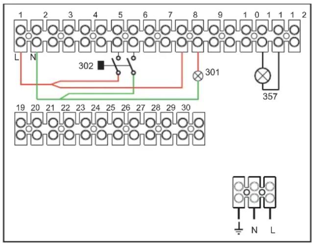
fig. 52
2.4 Gas connection

Before making the connection, check that the unit is arranged for operation with the type of fuel available and carefully clean all the system gas pipes to remove any residues that could affect proper functioning of the boiler.
Make sure all the gas connections are tight. The gas meter capacity must be suitable for the simultaneous use of all the units connected to it. The diameter of the gas pipe leaving the boiler is not decisive for choosing the diameter of the pipe between the unit and the meter; it must be chosen according to its length and pressure losses, in conformity with the current regulations.

Do not use the gas pipes to ground electrical appliances.
2.5 Electrical connections
Connection to the power supply

Electrical safety of the unit is obtained only when it is correctly connected to an effective grounding system as required by current safety standards. Have the efficiency and suitability of the grounding system checked by professionally qualified personnel; the Manufacturer declines any liability for damage caused by failure to ground the system. Also make sure the electrical system is adequate for the maximum power absorbed by the unit, as specified on the boiler data plate.
The boiler is pre-wired and equipped with a "Y" type connection cable to the electric line without plug. The connections to the mains must be made with a fixed connection and equipped with a double-pole switch with contact opening gap of at least 3 mm, interposing 16 A fuses max. between boiler and line. It is important to respect the polarity (LINE: brown wire / NEUTRAL: blue wire / GROUND: yellow-green wire) in the connections to the power line. When installing or replacing the power cable, the ground wire must be left 2 cm longer than the others.

The unit's power cable must not be replaced by the user. If the cable gets damaged, turn the unit off and have the cable replaced only by professionally qualified personnel. In case of power supply cable replacement, use only cable "HAR H05VV-F" 3 x 1.5 mm ^2 with a maximum external diameter of 8 mm.
Room thermostat (optional)

CAUTION: The room thermostat must have clean contacts. CONNECTING 230 V. TO THE TERMINALS OF THE ROOM THERMOSTAT WILL IRREPARABLY DAMAGE THE ELECTRONIC CARD.
When connecting a remote timer control or a timer switch, do not take the power supply for these devices from their cut-out contacts. Their power supply must be taken with a direct connection from the mains or with batteries, depending on the kind of device.
External probe (optional)
Connect the probe to its respective terminals. The maximum permissible length of the boiler – external probe connection electric cable is 50 m. A common 2-core cable can be used. The external probe should preferably be installed on the North, North-West wall or on the wall with most of the main living room. The probe must never be exposed to the sun in the early morning, and in general, as far as possible, it must not receive direct solar radiation; if necessary, it must be protected. In any case, the probe must never be mounted near windows, doors, ventilation openings, flues or heat sources that could affect the reading.

natural_image
Pure electrical circuit lines without any symbolsfig. 53- Positioning of external probe not recommended
Accessing the electrical terminal block
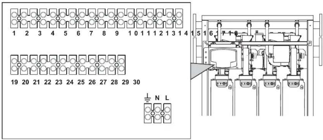
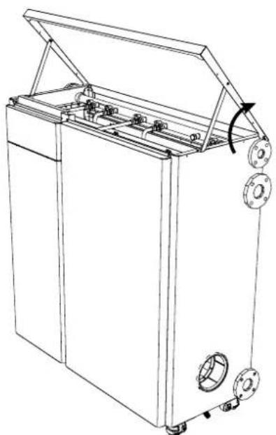
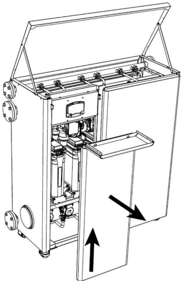
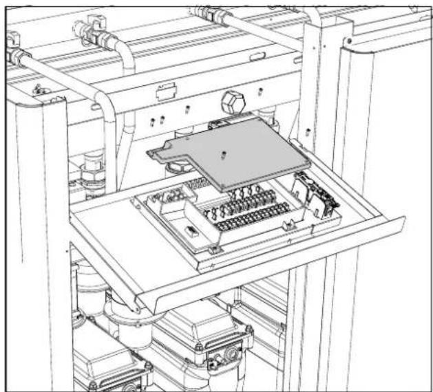
To access the electrical terminal block, lift the top panel and rotate the panel. Make the electrical connections as shown in the wiring diagram on fig. 99 and run the cables through the special cable glands.

fig. 54
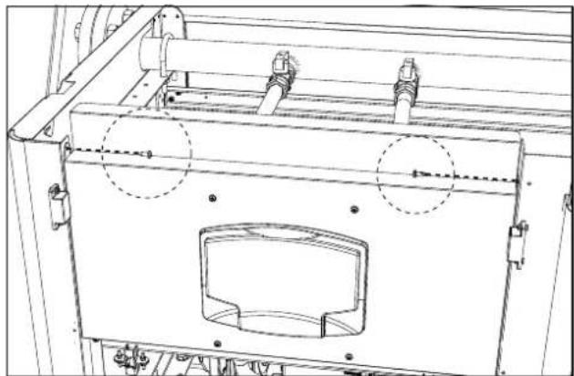
natural_image
Technical line drawing of a mechanical assembly with no visible text or symbolsfig. 56
natural_image
Technical line drawing of an industrial machine with internal components and directional arrows indicating flow or movement (no text or symbols present)fig. 55
natural_image
Technical line drawing of an industrial machine with internal components and piping (no text or symbols)fig. 57

fig. 58- Electrical terminal block
A Maximum applicable loads:
• Heating circulating pump: 230Vac 0.8A max, C=0.6
- 3-way valve: 230 Vac, 0.8 A max, COS = 0.6 for max 1 minute, 0.4 A continuous
• Alarm: 230 Vac, 0.8 A max, G06
2.6 Flue connection
Important
The unit is a B23-type with combustion air drawn from the place of installation, and fume exhaust by means of a fan (operation with flue pressurised), and must be connected to one of the discharge systems indicated below. Before proceeding with installation, check and carefully comply with the local regulations and provisions. Also, comply with the provisions on the positioning of wall and/or roof terminals and the minimum distances from windows, walls, ventilation openings, etc.
Manifold, ducts and flue must be suitably sized, designed and made in compliance with the current regulations. They must be made of suitable materials, i.e. resistant to heat and corrosion, smooth on the inside and tight. In particular, joints must be condensate proof. Also, provide for adequate condensate drainage points, connected to a trap to prevent the condensate formed in the flues from running into the generators.
Connection

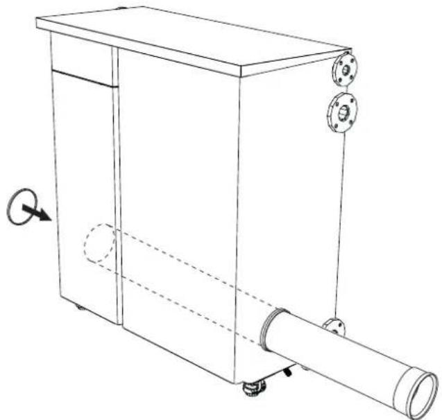
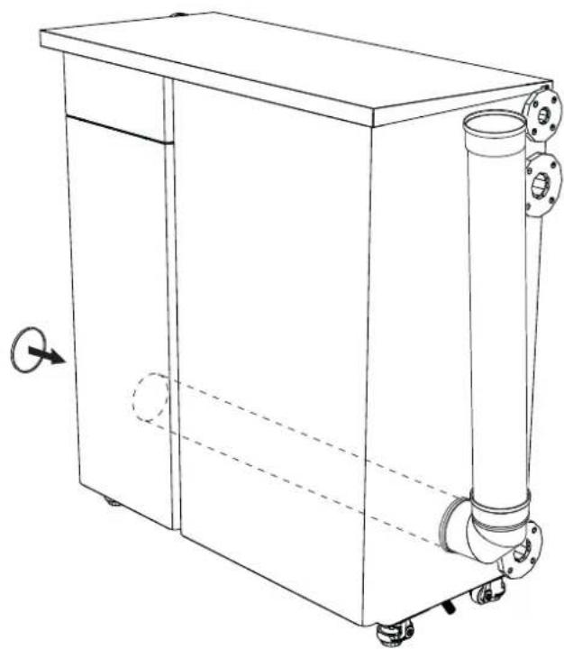
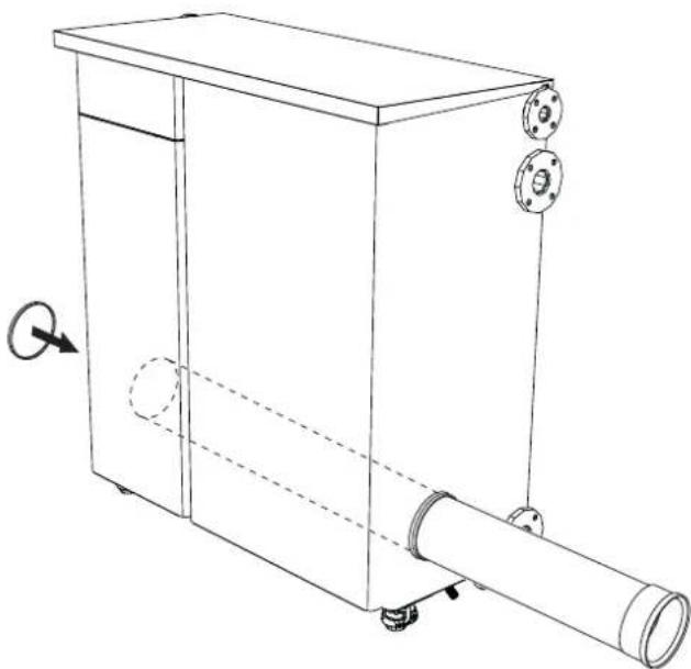
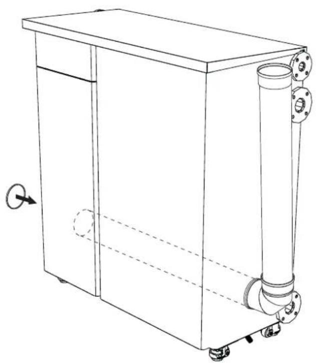
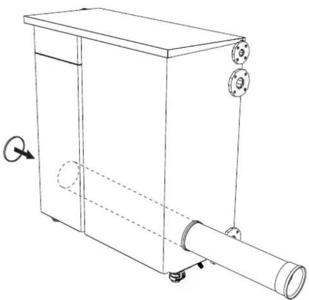
Every unit has two flue connections in order to offer greater flexibility in installation. Use only one of the outlets and check that the other is properly plugged (see fig. 59 - fig. 60 - fig. 61).

natural_image
Technical line drawing of a mechanical device with cylindrical components and mounting flanges (no text or symbols)fig. 59
natural_image
Line drawing of a rectangular industrial machine with cylindrical components and wheels, no text or symbols presentfig. 60
natural_image
Technical line drawing of a mechanical device with cylindrical components and mounting flanges (no text or symbols)fig. 61

Before making the flue connection fill the condensate trap with approx. 0.5 liters of water through the flue connections.
To calculate the maximum length of the fume ducts, refer to the maximum available head.
Maximum flue head = 185 Pa
2.7 Condensate drain connection
The boiler has a trap to drain condensate.

ATTENTION: The unit must never be operated with the trap empty!

natural_image
Technical line drawing of a mechanical assembly with multiple components and mounting feet (no text or symbols)fig. 62- Condensate drain connection
Neutralizer kit
The following condensate neutralizer kits are available on request:
code 051000X0 up to 320 kW
code 051001X0 up to 320 kW (with pump)
code 051002X0 up to 1500 kW
code 051003X0 up to 1500 kW (with pump)
Connect these neutralizers directly to the boiler drain without interposing the trap. The trap function is performed by the neutralizer itself.
3. Service and maintenance
All adjustment, conversion, commissioning and maintenance operations described below must only be carried out by Qualified Personnel (meeting the professional technical requirements of current regulations) such as the personnel of the Local After-Sales Technical Service.
FERROLI declines any liability for damage and/or injury caused by unqualified and unauthorized persons tampering with the unit.
3.1 Adjustments
Gas conversion
The unit can run on natural gas or LPG and is factory-set for use with one of these two gases, as clearly shown on the packing and on the data plate. Whenever a different gas to that for which the unit is set has to be used, the special conversion kit will be required, proceeding as follows:

DISCONNECT THE POWER and GAS to the boiler.
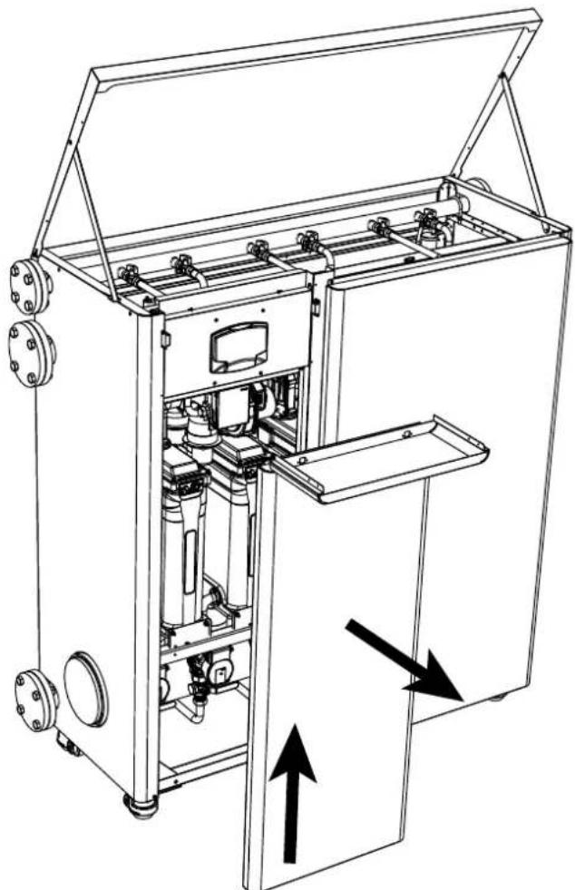
- Remove the panels (see fig. 86).
- Undo the screw "E" and remove the control unit from the gas valve (fig. 63).

- Remove the compensation tube "N" and loosen the screw "H" (see fig. 64).

fig. 64
- Rotate and remove the silencer "L" (see fig. 65).
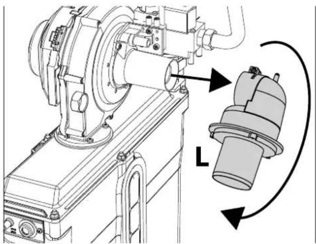
natural_image
Technical line drawing of a mechanical assembly with a rotating component and directional arrows (no text or symbols)fig. 65
- Loosen the swivels and disconnect the gas pipe "A" together with the cock "B" (fig. 66).

fig. 66
- Remove the "Venturi Group" from the fan by undo- ing the two screws "F" (fig. 67).

natural_image
Technical line drawing of a mechanical pump assembly with mounting flanges and a labeled component 'F' (no text or symbols beyond label)fig. 67
- Remove the Venturi "V" by undoing the 3 screws (see fig. 68).
Replace the gas nozzle "C", positioning it inside the gasket "D", with that contained in the conversion kit (see fig. 68). Reassemble the "Venturi Group" and secure it to the fan (see fig. 68 and fig. 67).
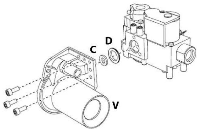
fig. 68
- In case of conversion to LPG, it is necessary to insert the nozzle "M" between the cock "B" and the gas manifold (fig. 69).
Reassemble the cock "B" on the gas manifold.
ATTENTION: The nozzle "M" (see fig. 69) must not be inserted with the unit running on Natural Gas.
ATTENTION: The chamfer of the diaphragm must face the gas manifold.

fig. 69- Nozzle for use with LPG
-
Reassemble all the components and check the seals.
-
Repeat the operations from point 3 to point 9 for each module.
-
Modify the parameter for the type of gas as described below.
Reach the screen shown in fig. 70, navigating in the menu and following the path "USER MENU → Maintenance Test Mode Gas Type Selection". Press contextual buttons 1 and 2 to select the type of gas. Confirm with the OK button.

fig. 70 - Gas type selection
- Apply the label, contained in the conversion kit, near the data plate.
Activation of TEST mode and combustion control of the individual modules
Press the button
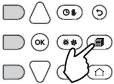
fig. 71
Using buttons 5 and 7, select the Test Mode menu.
Press OK

fig. 72
Using contextual buttons 1 and 2, select the number of the module control unit. Press OK
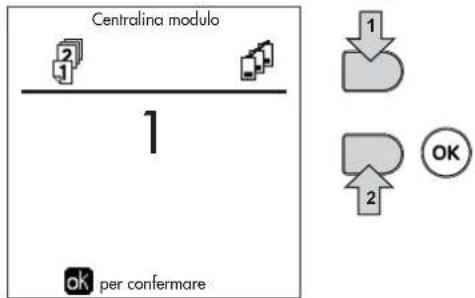
flowchart
graph TD
    A["Centralina modulo"] --> B["1"]
    B --> C["ok per confermare"]
    D["1"] --> E["2"]
    F["2"] --> G["OK"]
fig. 76
Using buttons 5 and 7, select the Maintenance menu. Press OK

fig. 73
The boiler ignites, reaching maximum heating power (Range Rated).

fig. 77- TEST mode (ex. heating power = 80%)
Using buttons 5 and 7, select the Test Mode menu.
Press OK

CO _2 control and measurement

The sampling of combustion fumes must be done by inserting the analyzer probe into the fumes outlet of the single module (see fig. 78).
AVOID SAMPLING FUMES FROM THE FLUE as the returned value will not be correct.

After performing the combustion analysis, always close the fumes outlet.
OTHERWISE, THERE IS A DANGER OF ASPHYSIA DUE TO COMBUSTION FUMES ESCAPING.
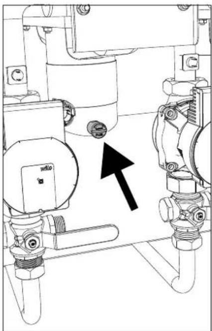
natural_image
Technical line drawing of industrial piping and valves with a black arrow indicating direction (no text or symbols)fig. 78- Single module fumes outlet
CO _2 measurement and adjustment at maximum heating capacity
• Using contextual button 1 (+) bring the value to 100%.
- Insert a combustion analysis instrument in the fumes outlet (see fig. 78).
- Check that the CO 2 value corresponds to:
9.1 % for Natural Gas
10.5 % for Propane Gas
- If the values do not correspond to those indicated, adjust the CO2 with the adjustment screw (see fig. 79), bringing them back to those indicated.

natural_image
Technical line drawing of a mechanical assembly with no visible text or symbolsfig. 79- Maximum capacity adjustment screw
Adjusting the CO_2 at minimum heating capacity
- Using contextual button 2 (-) bring the lue to 0%.
- Insert a combustion analysis instrument in the fumes outlet (see fig. 78).
- Check that the CO _2 value corresponds to: 8.5 % for Natural Gas 10.0 % for Propane Gas
- If the values do not correspond to those indicated, adjust the CO_2 with the OFFSET adjustment screw (see fig. 80), bringing them back to those indicated.
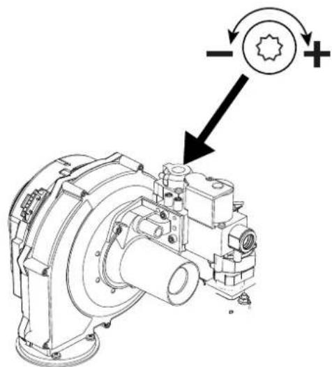
natural_image
Technical line drawing of a mechanical assembly with no visible text or symbolsfig. 80-OFFSET minimum capacity adjustment screw
REPEAT THE ENTIRE COMBUSTION CHECK PROCEDURE FOR ALL BOILER MODULES.

To exit the TEST mode, only use the "Stop Test" contextual button.

The TEST mode is automatically disabled in any case after 15 minutes.
DO NOT TURN OFF THE BOILER ELECTRICALLY DURING THE TEST.
Otherwise, when the power is switched on again, the system starts to work as if still in TEST mode and not like for a normal heating request.
Check of simultaneous activation of all modules
Within the Test Mode menu screen, select TEST (See fig. 82). Press OK

Using contextual button 2 immediately bring the value (-), to 0%
PREVENT THE BOILER FROM IMMEDIATELY OPERATING AT MAXIMUM POWER.
INCREASE THE POWER SLOWLY TO AVOID THERMAL SHOCK.
Reach the value of 100% power in a time of 2-3 minutes.

fig. 83
With all modules on at the same power (maximum or minimum), combustion can be checked at the boiler flue outlet.
Heating Capacity Adjustment (RANGE RATED)

This is a “RANGE RATED” boiler (according to EN 15502) and can be adjusted to the system's thermal requirement by setting the maximum heating capacity for operation in heating mode, as follows:
- Put the boiler in TEST mode (see sec. 3.1).
- Press the contextual buttons 1 and 2 to increase or decrease the heating capacity (minimum = 00 - maximum = 100). See the diagram “Heating Capacity Adjustment” (fig. 84).
- By pressing the OK button (detail 6 - fig. 1) the maximum heating capacity will remain that just set. Exit TEST mode (see sec. 3.1).
After setting the desired heating capacity, write the value on the sticker provided and place it on the boiler under the data plate. For subsequent checks and adjustments, refer to the set value.

THE HEATING CAPACITY ADJUSTMENT THUS MADE ENSURES THE EFFICIENCY VALUES DECLARED IN cap. 4.4 "Technical data table"
Heating capacity adjustment diagram
A = kW - B = Electronic Board Parameter
B

line
| A | 300 kW | 450 kW | 600 kW | | --- | ------ | ------ | ------ | | 60 | 0 | 0 | 0 | | 80 | 10 | 5 | 2 | | 100 | 20 | 10 | 5 | | 120 | 30 | 15 | 8 | | 140 | 40 | 20 | 12 | | 160 | 50 | 25 | 16 | | 180 | 60 | 30 | 20 | | 200 | 70 | 35 | 25 | | 220 | 80 | 40 | 30 | | 240 | 90 | 45 | 35 | | 260 | 100 | 50 | 40 | | 280 | 110 | 55 | 45 | | 300 | 120 | 60 | 50 | | 320 | 130 | 65 | 55 | | 340 | 140 | 70 | 60 | | 360 | 150 | 75 | 65 | | 380 | 160 | 80 | 70 | | 400 | 170 | 85 | 75 | | 420 | 180 | 90 | 80 | | 440 | 190 | 95 | 85 | | 460 | 200 | 100 | 90 | | 480 | 210 | | | | 500 | | | | | 520 | | | | | 540 | | | | | 560 | | | | | 580 | | | | | 600 | | | |fig. 84
TECHNICAL MENU
ONLY QUALIFIED PERSONNEL CAN ACCESS THE SERVICE MENU AND MODIFY PARAMETERS.
Accessing the Technical Menu is only possible after entering the code 4 1 8. It is valid for 15 minutes.
To copy a parameter to the other boiler modules, select the parameter from the list, press OK to enter the parameter and then press the button ECO/COMF (fig. 85). In this way the parameter is replicated on all modules.

It is advisable to make the various modules work with the same parameter values, in order to have optimal balance of the working point.
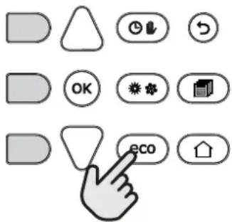
fig. 85
Configuration - Parameters Menu
19 parameters are available, indicated by the letter "b", which are not modifiable from Remote Timer Control.
Table 4- Parameters - Configuration
| Parameter Description Range | |||
| b01 Gas type selection Natural Gas/LPG Natural gas | |||
| b02 Boiler type selection | 1 = Heating only2 = Combi with storage tank with double pump3 = Combi with storage tank with diverter valve4 ÷ 9 = Not used | 1 | |
| b03 System water pressure protection selection | 0 = Pressure switch1 = Flow switch 1 sec2 = Flow switch 3 sec3 = Flow switch 5 sec4 = Flow switch 10 sec5 = Pressure transducer | 0 | |
| b04 Fan max. frequency in DHW 0-255 Hz 210 Hz | |||
| b05 Fan max. frequency in heating 0-255 Hz 210 Hz | |||
| b06 Fan min. frequency in DHW/heating 0-255 Hz 60 Hz | |||
| b07 Fan min. Frequency Offset 0-255 Hz 40 Hz | |||
| b08 Variable output Relay operation selection | 0=Burner lit1=Legionella pump2=Boiler room ventilation3=Motor-operated shutoff valve | 0 | |
| b09 | Post-Ventilation | 0-120 seconds | 30 |
| b10 | Boiler room pre-ventilation | 1-15 minutes | 1 |
| b11 | Boiler room post-ventilation | 1-15 minutes | 1 |
| b12 Fume sensor | OFF = Deactivated,ON = Enabled | OFF | |
| b13 Not implemented | 0 ÷ 90 °C | 45 | |
| b14 | Fumes Max Temperature | 0-125°C | 110 |
| b15 Fan type selection | -- | -- | |
| b16 Pump antiblock operation time 0-20 seconds | 5 | ||
| b17 High voltage input | 0 = Remote reset1 = Disable all modules2 = Not used3 = Enable heating request | 0 | |
| b18 Password | 0 ÷ 999 | 418 | |
| b19 Module Activation | ON-OFF | ON | |
Notes
- Parameters with more than one description vary their function and/or range in relation to the setting of the parameter given in brackets.
- Parameters with more than one description are reset to the default value if the parameter given in brackets is modified.
Parameters Menu - Transparent Parameters
31 parameters are available, indicated by the letter "P", which are not modifiable from Remote Timer Control.
Table 5- Parameters - Transparent
| Parameter Description Range | |||
| P01 Ignition power 0-100% 30 | |||
| P02 Heating ramp 1-10°C/minute 1 | |||
| P03 Virtual setpoint min. temperature 20 ÷ 80°C 20 | |||
| P04 Heating standby time 0 ÷ 10 minutes 4 | |||
| P05 Heating Post-Circulation 0 ÷ 255 minutes 3 | |||
| P06 | Pump operation | 0-3 Operation strategy | 0 |
| P07 | Modulating pump min. speed | 0 ÷ 100% | 30 |
| P08 | Modulating pump start speed | 0 ÷ 100% | 75 |
| P09 | Modulating pump max. speed | 30 ÷ 100% | 100 |
| P10 | Pump deactivation temperature during Post-Circulation | 0 ÷ 100°C | 35 |
| P11 | Pump activation hysteresis temperature during Post-Circulation | 0 ÷ 20°C | 5 |
| P12 | Heating user min. setpoint | 10 ÷ 90 °C | 20 |
| P13 | Heating user max. setpoint | 20 ÷ 90 °C | 80 |
| P14 Max. output in heating 0-100% 80 | |||
| P15 DHW ramp 1-10°C/min 5 | |||
| P16 | DHW standby time | 0-255 seconds | 120 |
| P17 | DHW pump Post-Circulation | 0-255 seconds | 30 |
| P18 | With B02 = 7 - Not implemented | -- | -- |
| With B02 = 8 - DHW user min. setpoint | 10° ÷ 40° | 10° | |
| With B02 = 9 - DHW user min. setpoint | 10° ÷ 40° | 10° | |
| P19 | With B02 = 7 - Not implemented | -- | -- |
| With B02 = 8 - DHW user max. setpoint | 40° ÷ 70° | 65° | |
| With B02 = 9 - DHW user max. setpoint | 40° ÷ 70° | 65° | |
| P20 | Max. output in DHW | 0-100% | 80% |
| P21 | With B02 = 7 - Not implemented | -- | -- |
| With B02 = 8 - Hot water tank hysteresis | 0° ÷ 60° | 2° | |
| With B02 = 9 - Hot water tank hysteresis | 0° ÷ 60° | 2° | |
| P22 | With B02 = 7 - Not implemented | -- | -- |
| With B02 = 8 - Primary setpoint | 70° ÷ 85° | 80° | |
| With B02 = 9 - Primary setpoint | 70° ÷ 85° | 80° | |
| P23 | With B02 = 7 - Not implemented | -- | -- |
| With B02 = 8 - Legionella protection | ON - OFF | OFF | |
| With B02 = 9 - Legionella protection | ON - OFF | OFF | |
| P24 | Fan frequency in standby mode | 0-255 Hz | 0 |
| P25 Modulating pump adjustment temperature 0-60°C | 20 | ||
| P26 | Primary exchanger protection temperature | 0-80°C | 35 |
| P27 | System min. pressure value | -- | -- |
| P28 | System nominal pressure value | -- | -- |
| P29 Exchanger protection intervention | 0 = No F43,1-15 = 1-15°C/second | 0 | |
| P30 | Heating hysteresis after ignition | 6-30°C | 10 |
| P31 | Timer for heating hysteresis after ignition | 0-180 seconds | 60 |
Notes
- Parameters with more than one description vary their function and/or range in relation to the setting of the parameter given in brackets.
- Parameters with more than one description are reset to the default value if the parameter given in brackets is modified.
- The Maximum Heating Power parameter can also be modified in Test Mode.
System Type - Parameters Menu
27 parameters are available, indicated by the letter "P." which are not modifiable from Remote Timer Control.
| Parameter | Description Range | ||
| P.01 | Heating request selection | 0 = Normal heating request1 = Request from remote control with external on-off enabling2 = 0-10V signal request with temperature control with external on-off enabling3 = 0-10V signal request with external on-off enabling4 = Control of 2 climatic curves with remote control-room thermostat and second room thermostat5 = Control of 2 climatic curves with remote control-room thermostat and second room thermostat | 0 |
| P.02 | Cascade sensor selection | 0 = Disabled1 = Enabled2 = Enabled | 0 |
| P.03 | No function 0-1 0 | ||
| P.04 | 3-way valve time 0 ÷ 255 seconds 0 | ||
| P.05 | Activation timer* 0 ÷ 255 minutes 1 | ||
| P.06 | Deactivation timer* 0 ÷ 255 minutes 1 | ||
| P.07 | Activation power* 0 ÷ 100% 70 | ||
| P.08 | Deactivation power* 0 ÷ 100% 25 | ||
| P.09 | Hydraulic separator function | OFF = Disabled, ON = Enabled | OFF |
| P.10 | System filling function | OFF = Disabled, ON = Enabled | OFF |
| P.11 | 3-way valve selection | 2/3 = 2 or 3 wires2 = 2 wires | 2/3 |
| P.12 | 0-10Vdc Heating OFF voltage (Temperature Control)** | 0.1-10 Vdc | 2.5 |
| P.13 | 0-10Vdc Heating ON voltage (Temperature Control)** | 0.1-10 Vdc | 3.0 |
| P.14 | 0-10Vdc Max. voltage (Temperature Control)** | 0.1-10 Vdc | 10 |
| P.15 | 0-10Vdc Min. temperature (Temperature Control)** | 0 ÷ 100°C | 20 |
| P.16 | 0-10Vdc Max. temperature (Temperature Control)** | 0 ÷ 100°C | 90 |
| P.17 | 0-10Vdc Heating OFF voltage (Power Control)** | 0.1-10 Vdc | 2.5 |
| P.18 | 0-10Vdc Heating ON voltage (Power Control)** | 0.1-10 Vdc | 3.0 |
| P.19 | 0-10Vdc Max. power (Power Control)** | 0.1-10 Vdc | 10 |
| P.20 | 0-10Vdc Min. power (Power Control)** | 0-100% | 0 |
| P.21 | 0-10Vdc Max. power (Power Control)** | 0-100% | 100 |
| P.22 | NOT USED -- | OFF | |
| P.23 | Slave boiler continuous Comfort | OFF = Disabled, ON = Enabled | OFF |
| P.24 | Activation timer *** 0 ÷ 255 minutes 1 | ||
| P.25 | Deactivation timer *** 0 ÷ 255 minutes 5 | ||
| P.26 | Activation power *** | 0 ÷ 100 % | 70 |
| P.27 | Deactivation power *** | 0 ÷ 100 % | 25 |
Notes
- * These parameters regard heating mode.
- ** These parameters are active only when the system operates with input 0-10Vdc.
- *** These parameters regard DHW mode.
3.2 Commissioning

Checks to be done at first lighting, and after all maintenance operations that involved disconnection from the systems or work on safety devices or parts of the boiler:
Before lighting the boiler
- Open any on-off valves between the boiler and the systems.
- Check the tightness of the gas system, proceeding with caution and using a soap and water solution to detect any leaks in connections.
- Check correct prefilling of the expansion tank (ref. sec. 4.4).
- Fill the water system and make sure all air contained in the boiler and the system has been vented, by opening the air vent valve on the boiler and any vent valves on the system.
- Fill the condensate trap and check correct connection of the condensate elimination system.
- Make sure there are no water leaks in the system, DHW circuits, connections or boiler.
- Check correct connection of the electrical system and efficiency of the earthing system
- Make sure the gas pressure value for heating is that required.
- Make sure there are no flammable liquids or materials in the immediate vicinity of the boiler

IF THE ABOVE INSTRUCTIONS ARE NOT OBSERVED THERE MAY BE RISK OF SUFFOCATION OR POISONING DUE TO GAS OR FUMES ESCAPING; DANGER OF FIRE OR EXPLOSION. ALSO, THERE MAY BE A RISK OF ELECTRIC SHOCK OR FLOODING THE ROOM.
Checks during operation
- Turn the unit on as described in sec. 1.3.
- Check the tightness of the fuel circuit and water systems.
- Check the efficiency of the flue and air-fume ducts during boiler operation.
- Check the correct tightness and efficiency of the condensate removal system and trap.
- Check correct water circulation between the boiler and systems.
- Make sure the gas valve modulates correctly in heating and hot water production.
- Check proper lighting of the boiler by performing various tests, turning it on and off with the room thermostat or remote control.
- Using a combustion analyzer connected to the fumes outlet of the single module (see fig. 78), check the CO_2 content in the fumes.
• Make sure the fuel consumption indicated on the meter matches that given in the technical data table in sec. 4.4. - Check the correct programming of the parameters and carry out any required customization (compensation curve, power, temperatures, etc.).
3.3 Maintenance
IMPORTANT

ALL MAINTENANCE WORK AND REPLACEMENTS MUST BE CARRIED OUT BY SKILLED QUALIFIED PERSONNEL.
Before carrying out any operation inside the boiler, disconnect the power and close the gas cock upstream. Otherwise there may be a danger of explosion, electric shock, suffocation or poisoning.
Periodical inspection
To ensure proper operation of the unit, it is necessary to have an annual inspection carried out by qualified personnel, providing for the following:
- heat exchanger check and cleaning with suitable products if dirty or clogged
- check and possible cleaning of burner (do not use chemical products or wire brushes)
- seal and gasket check (burner, sealed chamber, etc.)
- check and cleaning of sludge remover filters and system filters
- check, cleaning and filling of condensate drain traps
- check of wiring, contacts, electrical actuators
- check and cleaning of generator air inlets and boiler room air intakes
- check and cleaning of fume evacuation duct-manifold-flue system.
- expansion tank check and prefilling
- check and cleaning of electrodes, which must be free of deposits and properly positioned
- check of correct and stable system water pressure, ensuring conformity with the required working pressure.

The use of automatic filling systems for reinstatement of operating conditions must provide for adequate treatment of the water (ref. "System water characteristics" on page 311)
- check of heating system water chemical and physical parameters (ref. "System water characteristics" on page 311)
• water and gas system tightness check - check of correct and stable gas supply pressure to plant (20 mbar for operation with natural gas); any fluctuations or pressure drops below the declared value can create malfunctioning and stops with need for manual resetting.
• burner ignition and control and safety device check (gas valve, flowmeter, thermostats, etc.)
• circulating pump check, freeing when necessary - fume analysis and check of combustion parameters

The casing, control panel and aesthetic parts of the boiler can be cleaned with a soft damp cloth, possibly soaked in soapy water. All abrasive detergents and solvents should be avoided.
Opening the casing
To open the boiler casing:
- Undo the screws A.
- Slide the cover towards the back so as to hook the pin as shown in the box in fig. 86.
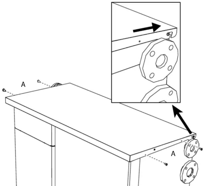
fig. 86- Cover opening
- Hook the bracket (see fig. 87)
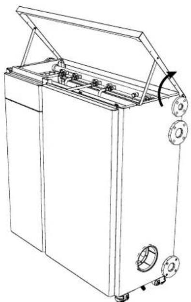
natural_image
Line drawing of a mechanical device with open lid, flanges, and internal components (no text or symbols)
natural_image
Technical line drawing of a mechanical assembly with no visible text or symbolsfig. 87
- Undo the screws, lift and remove the panels.

natural_image
Technical line drawing of an industrial machine with internal components and mounting brackets (no text or symbols)fig. 88
Module maintenance
The modular structure of MACH allows maintenance or replacement of parts to be carried out on the individual internal modules independently of each other.
Disconnect the unit from the power supply and close the gas cock (ref. 106 - fig. 89) of the module undergoing maintenance. If necessary, drain the hydraulic circuit by connecting the hose connector pre-installed in the first module, using a suitable rubber hose (not supplied), to a drain or a collection manifold, on the side outlet of the three-way cock (ref. 252 - fig. 89) located on the module return. Close the three-way cock (ref. 252) on the return in order to drain.
Once the maintenance operations have been carried out, proceed in reverse order, returning the three-way return cock (ref. 252) to the "open" position.

IMPORTANT: At the end of the maintenance operations, before turning the unit on again, check that all the module shutoff cocks are in the "open" position.

fig. 89
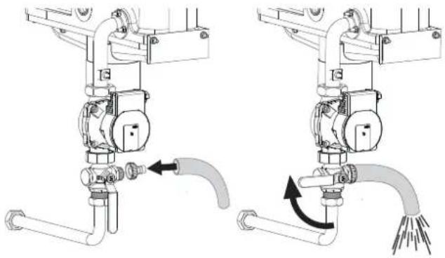
natural_image
Mechanical diagram showing two configurations of a valve assembly with tubing and tubing, no text or symbols present.fig. 90
3.4 Troubleshooting
Diagnostics
The boiler is equipped with an advanced self-diagnosis system. In case of a boiler fault, the display lights up indicating the fault code and the module number.
There are faults that cause permanent shutdowns (indicated with the symbol OK to reset): to restore operation, simply press the OK button for 1 second or via the RESET of the remote timer control (optional) if installed; if the boiler does not restart, the fault must be eliminated first.
Other faults cause temporary shutdowns which are automatically reset as soon as the value returns within the boiler's normal working range.
Table of faults
Table 6- List of faults
| Fault code | Fault Possible cause Cure | ||
| 01 No burner ignition | No gas | Check the regular gas flow to the boiler and that the air has been eliminated from the pipes | |
| Ignition/detection electrode fault | Check the wiring of the electrode and that it is correctly positioned and free of any deposits | ||
| Faulty gas valve Check the gas valve and replace it if necessary | |||
| Insufficient gas supply pressure Check the gas supply pressure | |||
| Trap blocked Check the trap and clean it if necessary | |||
| Card fault Check the card | |||
| 02 | Flame present signal with burner off | Electrode fault Check the ionization electrode wiring | |
| Card fault Check the card | |||
| 03 | Overtemperature protection intervention | Heating sensor damaged | Check the correct positioning and operation of the heating sensor |
| No water circulation in the system Check the circulating pump | |||
| Air in the system Vent the system | |||
| 05 | Fan protection intervention | Fault F15 generated for 1 hour (consecutive) | See fault F15 |
| 06 | No flame after ignition phase (6 times in 4 minutes) | Ionization electrode fault Check the position of the ionization electrode and replace it if necessary | |
| Flame unstable Check the burner | |||
| Gas valve Offset fault Check the Offset adjustment at minimum power | |||
| air/fume ducts obstructed | Remove the obstruction from the flue, fume extraction ducts, air inlet and terminals | ||
| Trap blocked Check the trap and clean it if necessary | |||
| 07 High fume temperature | Exchanger dirty | Clean the exchanger | |
| Exchanger deteriorated | Check the integrity of exchanger | ||
| Sensor does not indicate the correct temperature | Check the fume sensor or replace it | ||
| 08 | Heating sensor 1 (flow) overtemperature indication(Viewable only in History Menu) | insufficient system water circulation | check water circulation |
| 09 | Return sensor overtemperature indication(Viewable only in History Menu) | insufficient system water circulation | check water circulation |
| 10 Flow sensor 1 fault | Sensor damaged | Check the wiring or replace the sensor | |
| Wiring shorted | |||
| Wiring disconnected | |||
| Fault code | Fault | Possible cause | Cure | |
| 11 Return sensor fault | Sensor damaged | Check the wiring or replace the sensorWiring shorted | ||
| Wiring disconnected | ||||
| 12 DHW sensor fault | Sensor damaged | Check the wiring or replace the sensorWiring shorted | ||
| Wiring disconnected | ||||
| 13 Card parameter fault Wrong card parameter setting | Check the card parameter and modify it if necessary. | |||
| 14 Flow sensor 2 fault | Sensor damaged | Check the wiring or replace the sensorWiring shorted | ||
| Wiring disconnected | ||||
| 15 Fan fault | No 230V power supply Check the 3-pin connector wiring | |||
| Tachometric signal interrupted Check the 5-pin connector wiring | ||||
| Fan damaged Check the fan | ||||
| 26 | RESET button on controller on gas valve, fault. | RESET button on controller fitted on gas valve blocked or faulty. | Check the RESET button and replace the controller on the gas valve if necessary. | |
| 34 | Supply voltage under 170V | Electric mains trouble Check the electrical system | ||
| 35 | Faulty mains frequency | Electric mains trouble | Check the electrical system | |
| 37 | Pressure switch contact open | Low system pressure Check the system water pressure | ||
| 39 External probe fault | Probe damaged or wiring shorted Check the wire wire wire wire wire wire wire wire wire wire wire wire wire wire wire wire wire wire wire wire wire wire wire wire wire wire wire wire wire wire wire wire wire wire wire wire wire wire wire wire wire wire wire wire wire wire wire wire wire wire wire wire wire wire wire wire wire wire wire wire wire wire wire wire wire wire wire wire wire wire wire wire wire wire wire wire wire wire wire wire wire wire wire wire wire wire wire wire wire wire wire wire wire wire wire wire wire wire wire wire cable wire wire wire wire wire wire wire wire wire wire wire wire wire wire wire wire wire wire wire wire wire wire wire wire wire wire wire wire wire wire wire wire wire wire wire wire wire wire wire wire wire wire wire wire wire wire wire wire wire wire wire wire wire wire wire wire wire wire wire wire wire wire wire wire wire wire wire wire wire wire wire wire wire wire wire wire wire wire wire wire wire wire wire wire wire wire wire wire wire wire wire wire wire wire wire wire wire wire wire line wire wire wire wire wire wire wire wire wire wire wire wire wire wire wire wire wire wire wire wire wire wire wire wire wire wire wire wire wire wire wire wire wire wire wire wire wire wire wire wire wire wire wire wire wire wire wire wire wire wire wire wire wire wire wire wire wire wire wire wire wire wire wire wire wire wire wire wire wire wire wire wire wire wire wire wire wire wire wire wire wire wire wire wire wire wire wire wire wire wire wire wire wire wire wire wire wire wire wire绳 wire wire wire wire wire wire wire wire wire wire wire wire wire wire wire wire wire wire wire wire wire wire wire wire wire wire wire wire wire wire wire wire wire wire wire wire wire wire wire wire wire wire wire wire wire wire wire wire wire wire wire wire wire wire wire wire wire wire wire wire wire wire wire wire wire wire wire wire wire wire wire wire wire wire wire wire wire wire wire wire wire wire wire wire wire wire wire wire wire wire wire wire wire wire wire wire wire wire wireWire wire wire wire wire wire wire wire wire wire wire wire wire wire wire wire wire wire wire wire wire wire wire wire wire wire wire wire wire wire wire wire wire wire wire wire wire wire wire wire wire wire wire wire wire wire wire wire wire wire wire wire wire wire wire wire wire wire wire wire wire wire wire wire wire wire wire wire wire wire wire wire wire wire wire wire wire wire wire wire wire wire wire wire wire wire wire wire wire wire wire wire wire wire wire wire wire wire wire wire Wire wire wire wire wire wire wire wire wire wire wire wire wire wire wire wire wire wire wire wire wire wire wire wire wire wire wire wire wire wire wire wire wire wire wire wire wire wire wire wire wire wire wire wire wire wire wire wire wire wire wire wire wire wire wire wire wire wire wire wire wire wire wire wire wire wire wire wire wire wire wire wire wire wire wire wire wire wire wire wire wire wire wire wire wire wire wire wire wire wire wire wire wire wire wire wire wire wire wire wire wires wire wire wire wire wire wire wire wire wire wire wire wire wire wire wire wire wire wire wire wire wire wire wire wire wire wire wire wire wire wire wire wire wire wire wire wire wire wire wire wire wire wire wire wire wire wire wire wire wire wire wire wire wire wire wire wire wire wire wire wire wire wire wire wire wire wire wire wire wire wire wire wire wire wire wire wire wire wire wire wire wire wire wire wire wire wire wire wire wire wire wire wire wire wire wire wire wire wire wire tie wire wire wire wire wire wire wire wire wire wire wire wire wire wire wire wire wire wire wire wire wire wire wire wire wire wire wire wire wire wire wire wire wire wire wire wire wire wire wire wire wire wire wire wire wire wire wire wire wire wire wire wire wire wire wire wire wire wire wire wire wire wire wire wire wire wire wire wire wire wire wire wire wire wire wire wire wire wire wire wire wire wire wire wire wire wire wire wire wire wire wire wire wire wire wire wire wire wire wire coil wire wire wire wire wire wire wire wire wire wire wire wire wire wire wire wire wire wire wire wire wire wire wire wire wire wire wire wire wire wire wire wire wire wire wire wire wire wire wire wire wire wire wire wire wire wire wire wire wire wire wire wire wire wire wire wire wire wire wire wire wire wire wire wire wire wire wire wire wire wire wire wire wire wire wire wire wire wire wire wire wire wire wire wire wire wire wire wire wire wire wire wire wire wire wire wire wire wire wire-wire wire wire wire wire wire wire wire wire wire wire wire wire wire wire wire wire wire wire wire wire wire wire wire wire wire wire wire wire wire wire wire wire wire wire wire wire wire wire wire wire wire wire wire wire wire wire wire wire wire wire wire wire wire wire wire wire wire wire wire wire wire wire wire wire wire wire wire wire wire wire wire wire wire wire wire wire wire wire wire wire wire wire wire wire wire wire wire wire wire wire wire wire wire wire wire wire wire wire wire wire wire wire wire wire wire wire wire wire wire wire wire wire wire wire wire wire wire wire wire wire wire wire wire wire wire wire wire wire wire wire wire wire wire wire wire wire wire wire wire wire wire wire wire wire wire wire wire wire wire wire wire wire wire wire wire wire wire wire wire wire wire wire wire wire wire wire wire wire wire wire wire wire wire wire wire wire wire wire wire wire wire wire wire wire wire wire wire wire wire wire wire wire wire wire wire wire wire wire cable wire wire wire wire wire wire wire wire wire wire wire wire wire wire wire wire wire wire wire wire wire wire wire wire wire wire wire wire wire wire wire wire wire wire wire wire wire wire wire wire wire wire wire wire wire wire wire wire wire wire wire wire wire wire wire wire wire wire wire wire wire wire wire wire wire wire wire wire wire wire wire wire wire wire wire wire wire wire wire wire wire wire wire wire wire wire wire wire wire wire wire wire wire wire wire wire wire wire cable wirc wire wire wire wire wire wire wire wire wire wire wire wire wire wire wire wire wire wire wire wire wire wire wire wire wire wire wire wire wire wire wire wire wire wire wire wire wire wire wire wire wire wire wire wire wire wire wire wire wire wire wire wire wire wire wire wire wire wire wire wire wire wire wire wire wire wire wire wire wire wire wire wire wire wire wire wire wire wire wire wire wire wire wire wire wire wire wire wire wire wire wire wire wire wire wire wire wire wire wire wheel wire wire wire wire wire wire wire wire wire wire wire wire wire wire wire wire wire wire wire wire wire wire wire wire wire wire wire wire wire wire wire wire wire wire wire wire wire wire wire wire wire wire wire wire wire wire wire wire wire wire wire wire wire wire wire wire wire wire wire wire wire wire wire wire wire wire wire wire wire wire wire wire wire wire wire wire wire wire wire wire wire wire wire wire wire wire wire wire wire wire wire wire wire wire wire wire wire wire wire rail wire wire wire wire wire wire wire wire wire wire wire wire wire wire wire wire wire wire wire wire wire wire wire wire wire wire wire wire wire wire wire wire wire wire wire wire wire wire wire wire wire wire wire wire wire wire wire wire wire wire wire wire wire wire wire wire wire wire wire wire wire wire wire wire wire wire wire wire wire wire wire wire wire wire wire wire wire wire wire wire wire wire wire wire wire wire wire wire wire wire wire wire wire wire wire wire wire wire wire inter inter inter inter inter inter inter inter inter inter inter inter inter inter inter inter inter inter inter inter inter inter inter inter inter inter inter inter inter inter inter inter inter inter inter inter inter inter inter inter inter inter inter inter inter inter inter inter inter inter inter inter inter inter inter inter inter inter inter inter inter inter inter inter inter inter inter inter inter inter inter inter inter inter inter inter inter inter inter inter inter inter inter inter inter inter inter inter inter inter inter inter inter inter inter inter inter inter inter inter Inter inter inter inter inter inter inter inter inter inter inter inter inter inter inter inter inter inter inter inter inter inter inter inter inter inter inter inter inter inter inter inter inter inter inter inter inter inter inter inter inter inter inter inter inter inter inter inter inter inter inter inter inter inter inter inter inter inter inter inter inter inter inter inter inter inter inter inter inter inter inter inter inter inter inter inter inter inter inter inter inter inter inter inter inter inter inter inter inter inter inter inter inter inter inter inter inter inter inter interInter inter inter inter inter inter inter inter inter inter inter inter inter inter inter inter inter inter inter inter inter inter inter inter inter inter inter inter inter inter inter inter inter inter inter inter inter inter inter inter inter inter inter inter inter inter inter inter inter inter inter inter inter inter inter inter inter inter inter inter inter inter inter inter inter inter inter inter inter inter inter inter inter inter inter inter inter inter inter inter inter inter inter inter inter inter inter inter inter inter inter inter inter inter inter inter inter inter inter interinter inter inter inter inter inter inter inter inter inter inter inter inter inter inter inter inter inter inter inter inter inter inter inter inter inter inter inter inter inter inter inter inter inter inter inter inter inter inter inter inter inter inter inter inter inter inter inter inter inter inter inter inter inter inter inter inter inter inter inter inter inter inter inter inter inter inter inter inter inter inter inter inter inter inter inter inter inter inter inter inter inter inter inter inter inter inter inter inter inter inter inter inter inter inter inter inter inter inter inter ter inter inter inter inter inter inter inter inter inter inter inter inter inter inter inter inter inter inter inter inter inter inter inter inter inter inter inter inter inter inter inter inter inter inter inter inter inter inter inter inter inter inter inter inter inter inter inter inter inter inter inter inter inter inter inter inter inter inter inter inter inter inter inter inter inter inter inter inter inter inter inter inter inter inter inter inter inter inter inter inter inter inter inter inter inter inter inter inter inter inter inter inter inter inter inter inter inter inter inter inter inter inter inter inter inter inter inter inter inter inter inter inter inter inter inter inter inter inter inter inter inter inter inter inter inter inter inter inter inter inter inter inter inter inter inter inter inter inter inter inter inter inter inter inter inter inter inter inter inter inter inter inter inter inter inter inter inter inter inter inter inter inter inter inter inter inter inter inter inter inter inter inter inter inter inter inter inter inter inter inter inter inter inter inter inter inter inter inter inter inter inter inter inter inter inter inter inter inter inter Intermeter | Check the correct positioning and operation of the heating sensor | Replace the sensor | |
| 42 | Heating sensor fault | Sensor damaged | Replace the sensor | |
| 50 | Cascade temperature sensor fault | Sensor damaged | Check the wiring or replace the sensorWiring shorted | |
| Wiring disconnected | ||||
| 52 | Heating sensor fault | Sensor damaged | Replace the sensor | |
| 61 Controller fault Controller internal error | Check the ground connection and replace the controller if necessary. | |||
| 62 | No communication between controller and gas valve | Controller not connected | Connect the controller to the gas valve | |
| Valve damaged | Replace the valve | |||
| 63646566 | Controller fault | Controller internal error | Check the ground connection and replace the controller if necessary. | |
| 99 | No communication between controller and dis-play | Wiring disconnected | Check the wiring of the 6 wires between controller and display | |
4. Technical data and characteristics
Legend of figures cap. 4 "Technical data and characteristics"
a4 Fumes outlet - ∅ 200
R1 620 Ohm 1/4W
R (Module 2) 1k3 Ohm 1/4W
R (Module 3) 2k2 Ohm 1/4W
R (Module 4) 3k3 Ohm 1/4W
R (Module 5) 4k3 Ohm 1/4W
R (Module 6) 5k6 Ohm 1/4W
R (Module 7) 7k5 Ohm 1/4W
R (Module 8) 9k1 Ohm 1/4W
RT 120 Ohm 1/4W
F Fuse
7 Gas inlet - DN 40 flanged
10 System flow - DN 65 flanged
11 System return - DN 65 flanged
16 Fan
32 Heating circulating pump
36 Automatic air vent
44 Gas valve
72 Room thermostat (not supplied)
72b Second room thermostat (not supplied)
81 Ignition electrode
95 3-way valve - 2 wires (not supplied)
A = Heating phase
B = Neutral
98 Switch
106 Gas cock
114 Water pressure switch
130 DHW circulating pump (not supplied)
138 External probe (not supplied)
139 Remote timer control (not supplied)
155 Hot water tank temperature probe (not supplied)
179 Non-return valve
186 Return sensor
188 Ignition/Ionization electrode
191 Fumes temperature sensor.
193 Trap
252 3-way drain and shutoff cock
256 Modulating heating circulating pump signal
278 Double sensor (Safety + Heating)
298 Cascade temperature sensor (not supplied)
299 Input 0-10 Vdc
300 Burner lit contact (voltage-free contact)
301 Fault contact (voltage-free contact)
302 Remote reset input (230 Volt)
306 Heating system circulating pump (not supplied)
307 Heating system second circulating pump (not supplied)
348 3-way valve - 3 wires (not supplied)
A = Heating phase
B = Neutral
C = DHW phase
357 Faulty contact (230 Vac)
374 Aluminum exchanger
375 Silencer
4.1 Dimensions and connections
Front view for models MACH 150 - MACH 225 - MACH 300 - MACH 370 - MACH 450
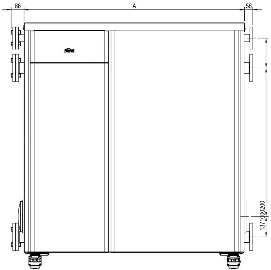
fig. 91- Front view
| Model | A mm |
| MACH 150 | |
| MACH 225 | 1047 |
| MACH 300 | |
| MACH 370 | 1487 |
| MACH 450 |
Front view for models MACH 520 - MACH 600

fig. 92
Side view
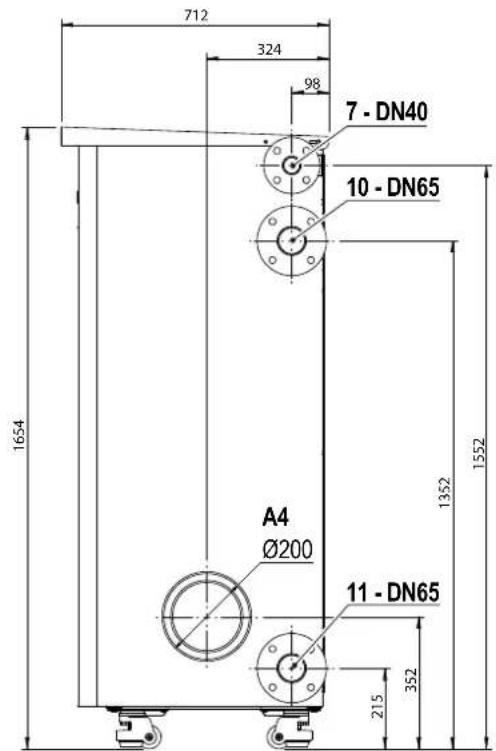
fig. 93- Side view
4.2 Main components

fig. 94- Main components
4.3 Hydraulic circuit

flowchart
graph TD
    A["Top Tank"] --> B["114 Valve"]
    B --> C["Valve 10"]
    B --> D["Valve 36"]
    B --> E["Valve 179"]
    B --> F["Valve 374"]
    B --> G["Valve 252 Valve"]
    B --> H["Valve 32 Valve"]
    B --> I["Valve 11 Valve"]
    B --> J["Valve 10 Valve"]
    style A fill:#f9f,stroke:#333
    style B fill:#ccf,stroke:#333
    style C fill:#cfc,stroke:#333
    style D fill:#cfc,stroke:#333
    style E fill:#cfc,stroke:#333
    style F fill:#cfc,stroke:#333
    style G fill:#fcc,stroke:#333
    style H fill:#fcc,stroke:#333
    style I fill:#fcc,stroke:#333
    style J fill:#fcc,stroke:#333
fig. 95- Hydraulic circuit
4.4 Technical data table
The column on the right gives the abbreviation used on the data plate.
| 0MCMFAWA | MACH 150 |
| 0MCMJAWA | MACH 225 |
| 0MCMLAWA | MACH 300 |
| DESTINATION COUNTRIES | IT ES RO PL NL HU |
| GAS CATEGORY | II2HM3P (IT) II2H3P (ES) II2H3P (RO) II2E3P (PL) II2EK3P (NL) I2Hs (HU) |
| PRODUCT IDENTIFICATION CODES | 0MCMFAWA | 0MCMJAWA | 0MCMLAWA | ||
| Max. heating capacity | kW | 142 | 213 | 284 | Qn |
| Min. heating capacity | kW | 14 | 14 | 14 | Qn |
| Max. heat output in heating (80/60°C) | kW | 139,2 | 208,8 | 278,4 | Pn |
| Min. heat output in heating (80/60°C) | kW | 13,7 | 13,7 | 13,7 | Pn |
| Max. heat output in heating (50/30°C) | kW | 148,4 | 222,6 | 296,8 | Pn |
| Min. heat output in heating (50/30°C) | kW | 15,1 | 15,1 | 15,1 | Pn |
| Efficiency Pmax (80-60°C) | % | 98 | 98 | 98 | |
| Efficiency Pmin (80-60°C) | % | 97,7 | 97,7 | 97,7 | |
| Efficiency Pmax (50-30°C) | % | 104,5 | 104,5 | 104,5 | |
| Efficiency Pmin (50-30°C) | % | 108,2 | 108,2 | 108,2 | |
| Efficiency 30% | % | 108,8 | 108,8 | 108,8 | |
| Flue loss with burner ON (80/60) - Pmax / Pmin | % | 1,6 / 1,3 | 1,6 / 1,3 | 1,6 / 1,3 | |
| Shell loss with burner ON (80/60) - Pmax / Pmin | % | 0,36 / 1 | 0,36 / 1 | 0,36 / 1 | |
| Flue loss with burner ON (50/30) - Pmax / Pmin | % | 1,2 / 0,6 | 1,2 / 0,6 | 1,2 / 0,6 | |
| Shell loss with burner ON (50/30) Pmax / Pmin | % | 0,14 / 0,4 | 0,14 / 0,4 | 0,14 / 0,4 | |
| Flue loss with burner OFF (50K / 20K) | % | 0 / 0 | 0 / 0 | 0 / 0 | |
| Shell loss with burner OFF (50K / 20K) | % | 0 / 0 | 0 / 0 | 0 / 0 | |
| Flue gas temperature (80/60 °C) - Pmax / Pmin | % | 62 / 60 | 62 / 60 | 62 / 60 | |
| Flue gas temperature (50/30 °C) - Pmax / Pmin | % | 48 / 31 | 48 / 31 | 48 / 31 | |
| Flue gas flow rate - Pmax / Pmin | % | 65,7 / 6,9 | 98,6 / 6,9 | 131,5 / 6,9 | |
| Gas supply pressure G20 | mbar | 20 | 20 | 20 | |
| Gas nozzle G20 | m3/h | 8,5 | 8,5 | 8,5 | |
| Gas flow rate G20 - Max / min | m3/h | 15,03 / 1,48 | 22,54 / 1,48 | 30,05 / 1,48 | |
| CO2 - G20 | % | 9,1±0,3 | 9,1±0,3 | 9,1±0,3 | |
| Gas supply pressure G31 | mbar | 37 | 37 | 37 | |
| Gas nozzle G31 | kg/h | 6.4 - 6.0 | 6.4 - 6.0 | 6.4 - 6.0 | |
| Gas flow rate G31 - Max / min | kg/h | 11,03 / 1,09 | 16,55 / 1,09 | 22,07 / 1,09 | |
| CO2 - G31 | % | 10,5±0,4 | 10,5±0,4 | 10,5±0,4 | |
| NOx emissions class | - | 6 (<56 mg/kwh) | NOx | ||
| Max. working pressure in heating | bar | 6 | 6 | 6 | PMS |
| Min. working pressure in heating | bar | 0,8 | 0,8 | 0,8 | |
| Heating max. adjustment temperature | °C | 95 | 95 | 95 | tmax |
| Heating water content | liters | 24 | 35 | 46 | |
| Heating expansion vessel capacity | liters | -- | -- | -- | |
| Heating expansion vessel precharge pressure | bar | -- | -- | -- | |
| Protection rating | IP | IPX4D | IPX4D | IPX4D | |
| Power supply voltage | V/Hz | 230V~50HZ | |||
| Electrical power input | W | 380 | 570 | 760 | W |
| Empty weight | kg | 215 | 255 | 290 | |
| Type of unit B23 | |||||
0MCMMAWA MACH 370
OMCMNAWA MACH 450
| DESTINATION COUNTRIES IT ES RO PL NL HU | ||||
| GAS CATEGORY II2HM3P (IT) II2H3P (ES) II2H3P (RO) II2E3P (PL) II2EK3P (NL) I2Hs (HU) | ||||
| PRODUCT IDENTIFICATION CODES | 0MCMMAWA | 0MCMNAWA | ||
| Max. heating capacity | kW | 355 | 426 | Qn |
| Min. heating capacity | kW | 14 | 14 | Qn |
| Max. heat output in heating (80/60°C) | kW | 348,1 | 417,7 | Pn |
| Min. heat output in heating (80/60°C) | kW | 13,7 | 13,7 | Pn |
| Max. heat output in heating (50/30°C) | kW | 371 | 445,2 | Pn |
| Min. heat output in heating (50/30°C) | kW | 15,1 | 15,1 | Pn |
| Efficiency Pmax (80-60°C) | % | 98 | 98 | |
| Efficiency Pmin (80-60°C) | % | 97,7 | 97,7 | |
| Efficiency Pmax (50-30°C) | % | 104,5 | 104,5 | |
| Efficiency Pmin (50-30°C) | % | 108,2 | 108,2 | |
| Efficiency 30% | % | 108,8 | 108,8 | |
| Flue loss with burner ON (80/60) - Pmax / Pmin | % | 1,6 / 1,3 | 1,6 / 1,3 | |
| Shell loss with burner ON (80/60) - Pmax / Pmin | % | 0,36 / 1 | 0,36 / 1 | |
| Flue loss with burner ON (50/30) - Pmax / Pmin | % | 1,2 / 0,6 | 1,2 / 0,6 | |
| Shell loss with burner ON (50/30) Pmax / Pmin | % | 0,14 / 0,4 | 0,14 / 0,4 | |
| Flue loss with burner OFF (50K / 20K) | % | 0 / 0 | 0 / 0 | |
| Shell loss with burner OFF (50K / 20K) | % | 0 / 0 | 0 / 0 | |
| Flue gas temperature (80/60 °C) - Pmax / Pmin | % | 62 / 60 | 62 / 60 | |
| Flue gas temperature (50/30 °C) - Pmax / Pmin | % | 48 / 31 | 48 / 31 | |
| Flue gas flow rate - Pmax / Pmin | % | 164,3 / 6,9 | 197,2 / 6,9 | |
| Gas supply pressure G20 | mbar | 20 | 20 | |
| Gas nozzle G20 | m3/h | 8,5 | 8,5 | |
| Gas flow rate G20 - Max / min | m3/h | 37,57 / 1,48 | 45,08 / 1,48 | |
| CO2 - G20 | % | 9,1±0,3 | 9,1±0,3 | |
| Gas supply pressure G31 | mbar | 37 | 37 | |
| Gas nozzle G31 | kg/h | 6.4 - 6.0 | 6.4 - 6.0 | |
| Gas flow rate G31 - Max / min | kg/h | 27,58 / 1,09 | 33,1 / 1,09 | |
| CO2 - G31 | % | 10,5±0,4 | 10,5±0,4 | |
| NOx emissions class | - | 6 (<56 mg/kwh) | NOx | |
| Max. working pressure in heating | bar | 6 | 6 | PMS |
| Min. working pressure in heating | bar | 0,8 | 0,8 | |
| Heating max. adjustment temperature | °C | 95 | 95 | tmax |
| Heating water content | liters | 57 | 68 | |
| Heating expansion vessel capacity | liters | -- | -- | |
| Heating expansion vessel precharge pressure | bar | -- | -- | |
| Protection rating | IP | IPX4D | IPX4D | |
| Power supply voltage | V/Hz | 230V~50HZ | ||
| Electrical power input | W | 950 | 1140 | W |
| Empty weight | kg | 355 | 395 | |
| Type of unit B23 | ||||
0MCMPAWA MACH 520
OMCMQAWA MACH 600
DESTINATION COUNTRIES
GAS CATEGORY
IT ES RO PL NL HU
II2HM3P (IT) II2H3P (ES) II2H3P (RO) II2E3P (PL) II2EK3P (NL) I2Hs (HU)
| PRODUCT IDENTIFICATION CODES | 0MCMPAWA | 0MCMQAWA | ||
| Max. heating capacity | kW | 497 | 568 | Qn |
| Min. heating capacity | kW | 14 | 14 | Qn |
| Max. heat output in heating (80/60°C) | kW | 487,3 | 556,9 | Pn |
| Min. heat output in heating (80/60°C) | kW | 13,7 | 13,7 | Pn |
| Max. heat output in heating (50/30°C) | kW | 519,4 | 593,6 | Pn |
| Min. heat output in heating (50/30°C) | kW | 15,1 | 15,1 | Pn |
| Efficiency Pmax (80-60°C) | % | 98 | 98 | |
| Efficiency Pmin (80-60°C) | % | 97,7 | 97,7 | |
| Efficiency Pmax (50-30°C) | % | 104,5 | 104,5 | |
| Efficiency Pmin (50-30°C) | % | 108,2 | 108,2 | |
| Efficiency 30% | % | 108,8 | 108,8 | |
| Flue loss with burner ON (80/60) - Pmax / Pmin | % | 1,6 / 1,3 | 1,6 / 1,3 | |
| Shell loss with burner ON (80/60) - Pmax / Pmin | % | 0,36 / 1 | 0,36 / 1 | |
| Flue loss with burner ON (50/30) - Pmax / Pmin | % | 1,2 / 0,6 | 1,2 / 0,6 | |
| Shell loss with burner ON (50/30) Pmax / Pmin | % | 0,14 / 0,4 | 0,14 / 0,4 | |
| Flue loss with burner OFF (50K / 20K) | % | 0 / 0 | 0 / 0 | |
| Shell loss with burner OFF (50K / 20K) | % | 0 / 0 | 0 / 0 | |
| Flue gas temperature (80/60 °C) - Pmax / Pmin | % | 62 / 60 | 62 / 60 | |
| Flue gas temperature (50/30 °C) - Pmax / Pmin | % | 48 / 31 | 48 / 31 | |
| Flue gas flow rate - Pmax / Pmin | % | 230,1 / 6,9 | 262,9 / 6,9 | |
| Gas supply pressure G20 | mbar | 20 | 20 | |
| Gas nozzle G20 | m3/h | 8,5 | 8,5 | |
| Gas flow rate G20 - Max / min | m3/h | 52,59 / 1,48 | 60,11 / 1,48 | |
| CO2 - G20 | % | 9,1±0,3 | 9,1±0,3 | |
| Gas supply pressure G31 | mbar | 37 | 37 | |
| Gas nozzle G31 | kg/h | 6.4 - 6.0 | 6.4 - 6.0 | |
| Gas flow rate G31 - Max / min | kg/h | 38,62 / 1,09 | 44,13 / 1,09 | |
| CO2 - G31 | % | 10,5±0,4 | 10,5±0,4 | |
| NOx emissions class | - | 6 (<56 mg/kwh) | NOx | |
| Max. working pressure in heating | bar | 6 | 6 | PMS |
| Min. working pressure in heating | bar | 0,8 | 0,8 | |
| Heating max. adjustment temperature | °C | 95 | 95 | tmax |
| Heating water content | liters | 79 | 90 | |
| Heating expansion vessel capacity | liters | -- | -- | |
| Heating expansion vessel precharge pressure | bar | -- | -- | |
| Protection rating | IP | IPX4D | IPX4D | |
| Power supply voltage | V/Hz | 230V~50HZ | ||
| Electrical power input | W | 1330 | 1520 | W |
| Empty weight | kg | 465 | 500 | |
| Type of unit | B23 | |||
4.5 ErP tables
ErP product fiche
MODEL: MACH 150 - (OMCMFAWA)
| Trademark: FERROLI | |||
| Condensing boiler: YES | |||
| Low-temperature boiler (**): YES | |||
| B1 Boiler: NO | |||
| Combination heater: NO | |||
| Cogeneration space heater: NO | |||
| Item | Symbol | Unit Value | |
| Rated heat output | Pn | kW | 139 |
| Seasonal space heating energy efficiency | _s | % | 93 |
| Useful heat out put | |||
| Useful heat output at rated heat output and high-temperature regime (*) | P4 | kW | 139,2 |
| Useful heat output at 30% of rated heat output and low-temperature regime (**) | P1 | kW | 23,0 |
| Useful efficiency | |||
| Useful efficiency at rated heat output and high-temperature regime (*) | _4 | % | 88,3 |
| Useful efficiency at 30% of rated heat output and low-temperature regime (**) | _1 | % | 98,0 |
| Auxiliary electricity consumption | |||
| At full load | elmax | kW | 0,230 |
| At part load | elmin | kW | 0,025 |
| In standby mode | PSB | kW | 0,005 |
| Other items | |||
| Standby heat loss | Pstby | kW | 0,240 |
| Ignition burner power consumption | Pign | kW | 0,000 |
| Annual energy consumption | QHE | GJ | 236 |
| Sound power level | LWA | dB | 69 |
| Emissions of nitrogen oxides | NOx | mg/kWh | 42 |
(*1 High-temperature regime means 60°C return temperature at heater inlet and 80°C feed temperature at heater outlet.
(**) Low temperature means for condensing boilers 30°C, for low-temperature boilers 37°C and for other heaters 50°C return temperature (at heater inlet).
ErP product fiche
MODEL: MACH 225 - (0MCMJAWA)
| Trademark: FERROLI | |||
| Condensing boiler: YES | |||
| Low-temperature boiler (**): YES | |||
| B1 Boiler: NO | |||
| Combination heater: NO | |||
| Cogeneration space heater: NO | |||
| Item | Symbol | Unit Value | |
| Rated heat output | Pn | kW | 209 |
| Seasonal space heating energy efficiency | _s | % | 93 |
| Useful heat out put | |||
| Useful heat output at rated heat output and high-temperature regime (*) | P4 | kW | 208,8 |
| Useful heat output at 30% of rated heat output and low-temperature regime (**) | P1 | kW | 23,0 |
| Useful efficiency | |||
| Useful efficiency at rated heat output and high-temperature regime (*) | _4 | % | 88,3 |
| Useful efficiency at 30% of rated heat output and low-temperature regime (**) | _1 | % | 98,0 |
| Auxiliary electricity consumption | |||
| At full load | elmax | kW | 0,345 |
| At part load | elmin | kW | 0,025 |
| In standby mode | PSB | kW | 0,006 |
| Other items | |||
| Standby heat loss | Pstby | kW | 0,360 |
| Ignition burner power consumption | Pign | kW | 0,000 |
| Annual energy consumption | QHE | GJ | 344 |
| Sound power level | LWA | dB | 71 |
| Emissions of nitrogen oxides | NOx | mg/kWh | 42 |
(*) High-temperature regime means 60°C return temperature at heater inlet and 80°C feed temperature at heater outlet.
(21) Low temperature means for condensing boilers 30°C, for low-temperature boilers 37°C and for other heaters 50°C return temperature (at heater inlet).
ErP product fiche
MODEL: MACH 300 - (OMCMLAWA)
| Trademark: FERROLI | |||
| Condensing boiler: YES | |||
| Low-temperature boiler (**): YES | |||
| B1 Boiler: NO | |||
| Combination heater: NO | |||
| Cogeneration space heater: NO | |||
| Item | Symbol | Unit Value | |
| Rated heat output | Pn | kW | 278 |
| Seasonal space heating energy efficiency | _s | % | 93 |
| Useful heat out put | |||
| Useful heat output at rated heat output and high-temperature regime (*) | P4 | kW | 278,4 |
| Useful heat output at 30% of rated heat output and low-temperature regime (**) | P1 | kW | 23,0 |
| Useful efficiency | |||
| Useful efficiency at rated heat output and high-temperature regime (*) | _4 | % | 88,3 |
| Useful efficiency at 30% of rated heat output and low-temperature regime (**) | _1 | % | 98,0 |
| Auxiliary electricity consumption | |||
| At full load | elmax | kW | 0,460 |
| At part load | elmin | kW | 0,025 |
| In standby mode | PSB | kW | 0,007 |
| Other items | |||
| Standby heat loss | Pstby | kW | 0,480 |
| Ignition burner power consumption | Pign | kW | 0,000 |
| Annual energy consumption | QHE | GJ | 452 |
| Sound power level | LWA | dB | 72 |
| Emissions of nitrogen oxides | NOx | mg/kWh | 42 |
(*) High-temperature regime means 60°C return temperature at heater inlet and 80°C feed temperature at heater outlet.
(21) Low temperature means for condensing boilers 30°C, for low-temperature boilers 37°C and for other heaters 50°C return temperature (at heater inlet).
ErP product fiche
MODEL: MACH 370 - (0MCMMAWA)
| Trademark: FERROLI | |||
| Condensing boiler: YES | |||
| Low-temperature boiler (**): YES | |||
| B1 Boiler: NO | |||
| Combination heater: NO | |||
| Cogeneration space heater: NO | |||
| Item | Symbol | Unit | Value |
| Rated heat output | Pn | kW | 348 |
| Seasonal space heating energy efficiency | _s | % | 93 |
| Useful heat out put | |||
| Useful heat output at rated heat output and high-temperature regime (*) | P4 | kW | 348,1 |
| Useful heat output at 30% of rated heat output and low-temperature regime (**) | P1 | kW | 23,0 |
| Useful efficiency | |||
| Useful efficiency at rated heat output and high-temperature regime (*) | _4 | % | 88,3 |
| Useful efficiency at 30% of rated heat output and low-temperature regime (**) | _1 | % | 98,0 |
| Auxiliary electricity consumption | |||
| At full load | elmax | kW | 0,575 |
| At part load | elmin | kW | 0,025 |
| In standby mode | PSB | kW | 0,008 |
| Other items | |||
| Standby heat loss | Pstby | kW | 0,600 |
| Ignition burner power consumption | Pign | kW | 0,000 |
| Annual energy consumption | QHE | GJ | 559 |
| Sound power level | LWA | dB | 74 |
| Emissions of nitrogen oxides | NOx | mg/kWh | 42 |
(*) High-temperature regime means 60°C return temperature at heater inlet and 80°C feed temperature at heater outlet.
(21) Low temperature means for condensing boilers 30°C, for low-temperature boilers 37°C and for other heaters 50°C return temperature (at heater inlet).
ErP product fiche
MODEL: MACH 450 - (0MCMNAWA)
| Trademark: FERROLI | |||
| Condensing boiler: YES | |||
| Low-temperature boiler (**): YES | |||
| B1 Boiler: NO | |||
| Combination heater: NO | |||
| Cogeneration space heater: NO | |||
| Item | Symbol | Unit Value | |
| Rated heat output | Pn | kW | 418 |
| Seasonal space heating energy efficiency | _s | % | 93 |
| Useful heat out put | |||
| Useful heat output at rated heat output and high-temperature regime (*) | P4 | kW | 417,7 |
| Useful heat output at 30% of rated heat output and low-temperature regime (**) | P1 | kW | 23,0 |
| Useful efficiency | |||
| Useful efficiency at rated heat output and high-temperature regime (*) | _4 | % | 88,3 |
| Useful efficiency at 30% of rated heat output and low-temperature regime (**) | _1 | % | 98,0 |
| Auxiliary electricity consumption | |||
| At full load | elmax | kW | 0,690 |
| At part load | elmin | kW | 0,025 |
| In standby mode | PSB | kW | 0,009 |
| Other items | |||
| Standby heat loss | Pstby | kW | 0,720 |
| Ignition burner power consumption | Pign | kW | 0,000 |
| Annual energy consumption | QHE | GJ | 667 |
| Sound power level | LWA | dB | 75 |
| Emissions of nitrogen oxides | NOx | mg/kWh | 42 |
(*) High-temperature regime means 60°C return temperature at heater inlet and 80°C feed temperature at heater outlet.
(21) Low temperature means for condensing boilers 30°C, for low-temperature boilers 37°C and for other heaters 50°C return temperature (at heater inlet).
ErP product fiche
MODEL: MACH 520 - (0MCMPAWA)
| Trademark: FERROLI | |||
| Condensing boiler: YES | |||
| Low-temperature boiler (**): YES | |||
| B1 Boiler: NO | |||
| Combination heater: NO | |||
| Cogeneration space heater: NO | |||
| Item | Symbol | Unit Value | |
| Rated heat output | Pn | kW | 487 |
| Seasonal space heating energy efficiency | _s | % | 93 |
| Useful heat out put | |||
| Useful heat output at rated heat output and high-temperature regime (*) | P4 | kW | 487,3 |
| Useful heat output at 30% of rated heat output and low-temperature regime (**) | P1 | kW | 23,0 |
| Useful efficiency | |||
| Useful efficiency at rated heat output and high-temperature regime (*) | _4 | % | 88,3 |
| Useful efficiency at 30% of rated heat output and low-temperature regime (**) | _1 | % | 98,0 |
| Auxiliary electricity consumption | |||
| At full load | elmax | kW | 0,805 |
| At part load | elmin | kW | 0,025 |
| In standby mode | PSB | kW | 0,010 |
| Other items | |||
| Standby heat loss | Pstby | kW | 0,840 |
| Ignition burner power consumption | Pign | kW | 0,000 |
| Annual energy consumption | QHE | GJ | 774 |
| Sound power level | LWA | dB | 77 |
| Emissions of nitrogen oxides | NOx | mg/kWh | 42 |
(*) High-temperature regime means 60°C return temperature at heater inlet and 80°C feed temperature at heater outlet.
(21) Low temperature means for condensing boilers 30°C, for low-temperature boilers 37°C and for other heaters 50°C return temperature (at heater inlet).
ErP product fiche
MODEL: MACH 600 - (0MCMQAWA)
| Trademark: FERROLI | |||
| Condensing boiler: YES | |||
| Low-temperature boiler (**): YES | |||
| B1 Boiler: NO | |||
| Combination heater: NO | |||
| Cogeneration space heater: NO | |||
| Item | Symbol | Unit Value | |
| Rated heat output | Pn | kW | 557 |
| Seasonal space heating energy efficiency | _s | % | 93 |
| Useful heat out put | |||
| Useful heat output at rated heat output and high-temperature regime (*) | P4 | kW | 556,9 |
| Useful heat output at 30% of rated heat output and low-temperature regime (**) | P1 | kW | 23,0 |
| Useful efficiency | |||
| Useful efficiency at rated heat output and high-temperature regime (*) | _4 | % | 88,3 |
| Useful efficiency at 30% of rated heat output and low-temperature regime (**) | _1 | % | 98,0 |
| Auxiliary electricity consumption | |||
| At full load | elmax | kW | 0,920 |
| At part load | elmin | kW | 0,025 |
| In standby mode | PSB | kW | 0,011 |
| Other items | |||
| Standby heat loss | Pstby | kW | 0,960 |
| Ignition burner power consumption | Pign | kW | 0,000 |
| Annual energy consumption | QHE | GJ | 882 |
| Sound power level | LWA | dB | 78 |
| Emissions of nitrogen oxides | NOx | mg/kWh | 42 |
(*) High-temperature regime means 60°C return temperature at heater inlet and 80°C feed temperature at heater outlet.
(21) Low temperature means for condensing boilers 30°C, for low-temperature boilers 37°C and for other heaters 50°C return temperature (at heater inlet).
4.6 Wiring diagrams
ATTENTION: Remove the jumper on the terminal block before connecting the room thermostat or the remote timer control.
ATTENTION: To connect the 3-way valve (terminals 13 - 14 - 15), refer to the diagrams of fig. 96 and fig. 97.

fig. 96- Connection of the 3-way valve with 2 wires

fig. 97- Connection of the 3-way valve with 3 wires
ATTENTION: In case of instability in the reading of the 0-10V signal by the electronic controller, it is advisable to connect the signal reference to ground, and insert a 10K resistor in parallel, as per fig. 98.
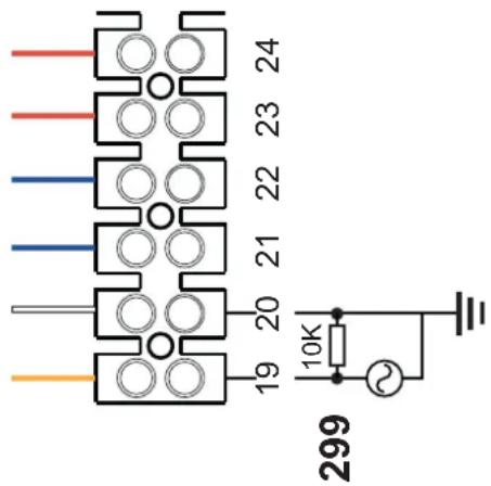
fig. 98-
Display wiring diagram

fig. 99- Display wiring diagram
First module wiring diagram
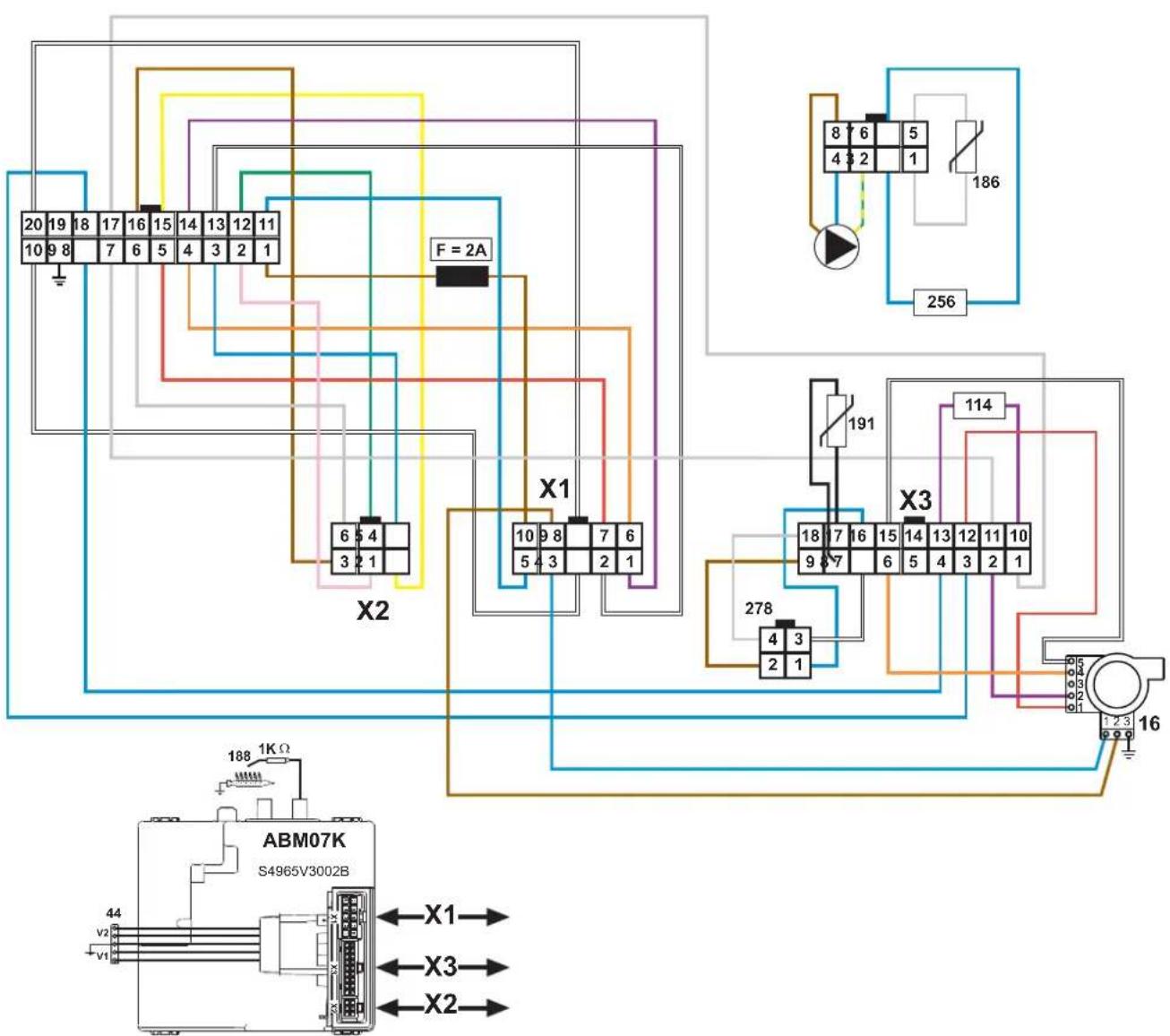
fig. 100- First module wiring diagram
Intermediate module wiring diagram

flowchart
graph TD
    subgraph_Component_1["ABM07K S4965V3002B"]
        A["Pin 14-18"] --> B["Pin 13-14"]
        B --> C["Pin 12-13"]
        C --> D["Pin 11-12"]
        D --> E["Pin 9-11"]
        E --> F["Pin 8-9"]
        F --> G["Pin 7-8"]
        G --> H["Pin 6-7"]
        H --> I["Pin 5-6"]
        I --> J["Pin 4-5"]
        J --> K["Pin 3-4"]
        K --> L["Pin 2-3"]
        L --> M["Pin 1-2"]
        M --> N["Pin 0-1"]
        N --> O["Pin 0-2"]
        O --> P["Pin 0-3"]
        P --> Q["Pin 0-4"]
        Q --> R["Pin 0-5"]
        R --> S["Pin 0-6"]
        S --> T["Pin 0-7"]
        T --> U["Pin 0-8"]
        U --> V["Pin 0-9"]
        V --> W["Pin 0-10"]
        W --> X["Pin 0-11"]
        X --> Y["Pin 0-12"]
        Y --> Z["Pin 0-13"]
        Z --> AA["Pin 0-14"]
        AA --> AB["Pin 0-15"]
        AB --> AC["Pin 0-16"]
        AC --> AD["Pin 0-17"]
        AD --> AE["Pin 0-18"]
        AE --> AF["Pin 0-19"]
        AF --> AG["Pin 0-20"]
        AG --> AH["Pin 0-21"]
        AH --> AI["Pin 0-22"]
        AI --> AJ["Pin 0-23"]
        AJ --> AK["Pin 0-24"]
        AK --> AL["Pin 0-25"]
        AL --> AM["Pin 0-26"]
        AM --> AN["Pin 0-27"]
        AN --> AO["Pin 0-28"]
        AO --> AP["Pin 0-29"]
        AP --> AQ["Pin 0-30"]
        AQ --> AR["Pin 0-31"]
        AR --> AS["Pin 0-32"]
        AS --> AT["Pin 0-33"]
        AT --> AU["Pin 0-34"]
        AU --> AV["Pin 0-35"]
        AV --> AW["Pin 0-36"]
        AW --> AX["Pin 0-37"]
        AX --> AY["Pin 0-38"]
        AY --> AZ["Pin 0-39"]
        AZ --> BA["Pin 0-40"]
        BA --> BB["Pin 0-41"]
        BB --> BC["Pin 0-42"]
        BC --> BD["Pin 0-43"]
        BD --> BE["Pin 0-44"]
        BE --> BF["Pin 0-45"]
        BF --> BG["Pin 0-46"]
        BG --> BH["Pin 0-47"]
        BH --> BI["Pin 0-48"]
        BI --> BJ["Pin 0-49"]
        BJ --> BK["Pin 0-50"]
        BK --> BL["Pin 0-51"]
        BL --> BM["Pin 0-52"]
        BM --> BN["Pin 0-53"]
        BN --> BO["Pin 0-54"]
        BO --> BP["Pin 0-55"]
        BP --> BQ["Pin 0-56"]
        BQ --> BR["Pin 0-57"]
        BR --> BS["Pin 0-58"]
        BS --> BT["Pin 0-59"]
        BT --> BU["Pin 0-60"]
        BU --> BV["Pin 0-61"]
        BV --> BW["Pin 0-62"]
        BW --> BX["Pin 0-63"]
        BX --> BY["Pin 0-64"]
        BY --> BZ["Pin 0-65"]
        BZ --> CA["Pin 0-66"]
        CA --> CB["Pin 0-67"]
        CB --> CC["Pin 0-68"]
        CC --> CD["Pin 0-69"]
        CD --> CE["Pin 0-70"]
        CE --> CF["Pin 0-71"]
        CF --> CG["Pin 0-72"]
        CG --> CH["Pin 0-73"]
        CH --> CI["Pin 0-74"]
        CI --> CJ["Pin 0-75"]
        CJ --> CK["Pin 0-76"]
        CK --> CL["Pin 0-77"]
        CL --> CM["Pin 0-78"]
        CM --> CN["Pin 0-79"]
        CN --> CO["Pin 0-80"]
        CO --> CP["Pin 0-81"]
        CP --> CQ["Pin 0-82"]
        CQ --> CR["Pin 0-83"]
        CR --> CS["Pin 0-84"]
        CS --> CT["Pin 0-85"]
        CT --> CU["Pin 0-86"]
        CU --> CV["Pin 0-87"]
        CV --> CW["Pin 0-88"]
        CW --> CX["Pin 0-89"]
        CX --> CY["Pin 0-90"]
    end
    subgraph Component_2
        X1["X1"] & X2["X2"] & X3["X3"] & X4["X4"] & X5["X5"] & X6["X6"] & X7["X7"] & X8["X8"] & X9["X9"] & X10["X10"] & X11["X11"] & X12["X12"] & X13["X13"] & X14["X14"] & X15["X15"] & X16["X16"] & X17["X17"] & X18["X18"] & X19["X19"] & X20["X20"] & X21["X21"] & X22["X22"] & X23["X23"] & X24["X24"] & X25["X25"] & X26["X26"] & X27["X27"] & X28["X28"] & X29["X29"] & X30["X30"] & X31["X31"] & X32["X32"] & X33["X33"] & X34["X34"] & X35["X35"] & X36["X36"] & X37["X37"] & X38["X38"] & X39["X39"] & X40["X40"] & X41["X41"] & X42["X42"] & X43["X43"] & X44["X44"] & X45["X45"] & X46["X46"] & X47["X47"] & X48["X48"] & X49["X49"] & X50["X50"] & X51["X51"] & X52["X52"] & X53["X53"] & X54["X54"] & X55["X55"] & X56["X56"] & X57["X57"] & X58["X58"] & X59["X59"] & X60["X60"] & X61["X61"] & X62["X62"] & X63["X63"] & X64["X64"] & X65["X65"] & X66["X66"] & X67["X67"] & X68["X68"] & X69["X69"] & X70["X70"] & X71["X71"] & X72["X72"] & X73["X73"] & X74["X74"] & X75["X75"] & X76["X76"] & X77["X77"] & X78["X78"] & X79["X79"] & X80["X80"] & X81["X81"] & X82["X82"] & X83["X83"] & X84["X84"] & X85["X85"] & X86["X86"] & X87["X87"] & X88["X88"] & X89["X89"] & X90["X90"] & X91["X91"] & X92["X92"] & X93["X93"] & X94["X94"] & X95["X95"] & X96["X96"] & X97["X97"] & X98["X98"] & X99["X99"] & X100["X100"]
fig. 101- Intermediate module wiring diagram
Last module wiring diagram
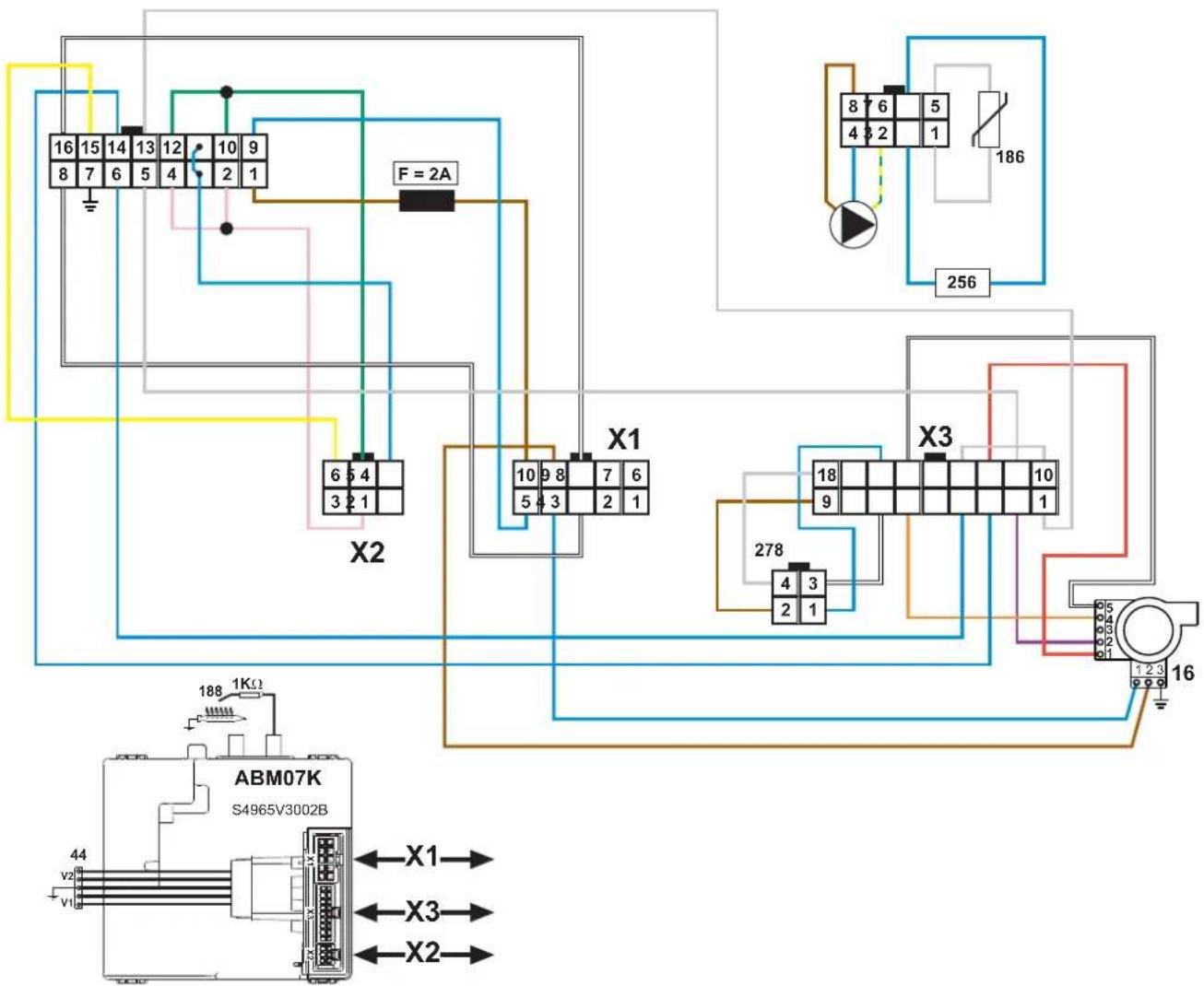
fig. 102- Last module wiring diagram
Module connection cables wiring diagram
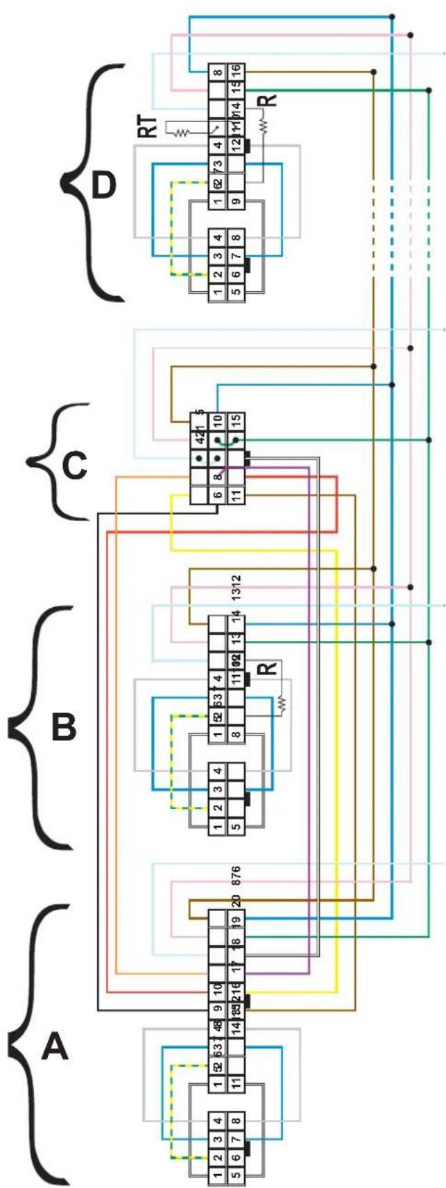
flowchart
graph TD
    A["Component A"] -->|1 2 3 4 5 6 7 8| B["Component B"]
    B -->|1 2 3 4 5 6 7 8| C["Component C"]
    C -->|1 2 3 4 5 6 7 8| D["Component D"]
    D -->|1 2 3 4 5 6 7 8| E["External Circuit"]
    style A fill:#f9f,stroke:#333
    style B fill:#bbf,stroke:#333
    style C fill:#bfb,stroke:#333
    style D fill:#ffb,stroke:#333
    style E fill:#ffb,stroke:#333
fig. 103- Module connection cable wiring diagram
Legend
A - First module
B - Intermediate module
C - Display
D - Last module

FERROLI S.p.A.
Via Ritonda 78/a
37047 San Bonifacio - Verona - ITALY
www.ferroli.com

- CE
- Posizionamento
- Manutenzione moduli
- Legenda figure cap. 4
- Emplazamiento
- Excludere boiler (economy)
- Oprirea centralei
- Reglarea temperaturii apei calde menajere (cu boiler optional instalat)
- Reducerea temperaturii apei calde menajere (cu boiler optional instalat)
- Pozitionarea
- Sarcini maxime aplicabile:
- Reglarea CO₂ la debitul termic minim
- REPETAȚI ÎNTREAGA PROCEDURĂ DE CONTROL A ARDERII PENTRU TOATE MODULELE CENTRALEI.
- Rezolvarea problemelor
- Diagnosticarea
- Ustawienie
- Konserwacja modułów
- Usuwanie usterek
- Diagnostyka
- Operating instructions .... 294
- Installation....308
- Service and maintenance.... 328
- Technical data and characteristics 343
- Operating instructions
- Introduction
- Control panel
- Legend
- Contextual button
- Direct buttons
- Menu/navigation buttons
- Menu structure
- Indication during operation
- Heating
- DHW circuit (with optional hot water tank installed)
- Exclude hot water tank (economy)
- Information
- Lighting and shutdown
- Boiler lighting
- Settings
- Contrast adjustment
- Date and Time Adjustment
- Boiler shutdown
- Adjustments
- Summer/Winter Switchover
- Heating temperature adjustment
- Heating temperature reduction
- DHW temperature adjustment (with optional hot water tank installed)
- DHW temperature reduction (with optional hot water tank installed)
- Time programming
- Legionella programming (with optional hot water tank installed)
- ATTENTION
- Holiday Function
- Service Intervention Date
- Service Information
- Room temperature adjustment (with optional room thermostat)
- Room temperature adjustment (with optional remote timer control)
- Sliding Temperature
- Compensation curve and curve offset
- Outside Temperature Heating OFF
- Adjustments from remote timer control
- System water pressure adjustment
- Installation
- General Instructions
- Place of installation
- Handling
- Positioning
- Plumbing connections
- System water characteristics
- Hydraulic circuit examples
- Two direct heating circuits
- - Schematic diagram
- - Electrical connections
- Legend (fig. 41 and fig. 42)
- - Parameters
- "System Type Menu"
- - Optional features
- Legend (fig. 44 and fig. 45)
- "Configuration - Parameters Menu"
- A direct heating circuit and a DHW circuit with diverter valve (3-wire)
- Legend (fig. 47 and fig. 48)
- Two mixed heating circuits, one direct heating circuit and one DHW circuit with circulating pump
- - Parameters FZ4B
- Legend (fig. 52)
- Gas connection
- Electrical connections
- Connection to the power supply
- Room thermostat (optional)
- External probe (optional)
- Accessing the electrical terminal block
- A Maximum applicable loads:
- Flue connection
- Important
- Connection
- Condensate drain connection
- Neutralizer kit
- Service and maintenance
- Adjustments
- Gas conversion
- DISCONNECT THE POWER and GAS to the boiler.
- Activation of TEST mode and combustion control of the individual modules
- CO _2 control and measurement
- CO _2 measurement and adjustment at maximum heating capacity
- Adjusting the CO_2 at minimum heating capacity
- DO NOT TURN OFF THE BOILER ELECTRICALLY DURING THE TEST.
- Check of simultaneous activation of all modules
- Heating Capacity Adjustment (RANGE RATED)
- Heating capacity adjustment diagram
- TECHNICAL MENU
- Configuration - Parameters Menu
- Notes
- Parameters Menu - Transparent Parameters
- System Type - Parameters Menu
- Commissioning
- Before lighting the boiler
- IF THE ABOVE INSTRUCTIONS ARE NOT OBSERVED THERE MAY BE RISK OF SUFFOCATION OR POISONING DUE TO GAS OR FUMES ESCAPING; DANGER OF FIRE OR EXPLOSION. ALSO, THERE MAY BE A RISK OF ELECTRIC SHOCK OR FLOODING THE ROOM.
- Checks during operation
- Maintenance
- ALL MAINTENANCE WORK AND REPLACEMENTS MUST BE CARRIED OUT BY SKILLED QUALIFIED PERSONNEL.
- Periodical inspection
- Opening the casing
- Module maintenance
- Troubleshooting
- Diagnostics
- Table of faults
- Technical data and characteristics
- Legend of figures cap. 4 "Technical data and characteristics"
- Dimensions and connections
- Main components
- Technical data table
- ErP tables
- ErP product fiche
- Wiring diagrams
Brand : FERROLI
Model : Mach
Category : Central heating boiler