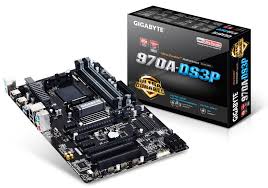
GIGABYTE GA-970A-DS3P - Motherboard

GA-970A-DS3P - Motherboard GIGABYTE - Free user manual and instructions

Find the device manual for free GA-970A-DS3P GIGABYTE in PDF.

📄 72 pages English EN Download 💬 AI Question 16 questions ⚙️ Specs
Notice GIGABYTE GA-970A-DS3P - page 1
Pick your language and provide your email: we'll send you a specifically translated version.
Product Type Motherboard
Brand GIGABYTE
Model GA-970A-DS3P
Form Factor ATX
CPU Socket AM3+
Chipset AMD 970 + SB950
Memory Type DDR3
Number of Memory Slots 4
Maximum Memory Capacity 32 GB
SATA Connectors 6 x SATA 3.0
Internal USB Connectors 2 x USB 3.0, 6 x USB 2.0
PCIe Connectors 1 x PCIe 2.0 x16, 3 x PCIe 2.0 x1, 2 x PCI
Required Power 24-pin ATX + 8-pin CPU
Dimensions 30.5 cm x 22.5 cm
Weight Approximately 0.8 kg
Main Features Supports AMD FX/Phenom II/Athlon II processors, 8-channel audio, Gigabit LAN, dual BIOS
Maintenance and Cleaning Disconnect power before cleaning. Use a dry cloth or an antistatic brush.
Safety Avoid any contact with live components. Handle socket pins with care.
Spare Parts and Repairability Spare parts not provided. Consult a professional for any repairs.
General Information User manual available online. Operating temperature: 0 °C to 40 °C.

Frequently Asked Questions - GA-970A-DS3P GIGABYTE

How to install the processor on the GA-970A-DS3P motherboard?
To install an AMD processor, lift the socket lever, align the triangle on the pin 1 with the socket triangle, insert the processor without forcing, then lower the lever to lock it. Be careful not to touch the socket contacts.
What type of RAM is compatible with this motherboard?
The GIGABYTE GA-970A-DS3P motherboard supports DDR3 memory. It has 4 slots and can accommodate up to 32 GB of RAM.
How to install memory modules?
Open the slot clips, align the notch of the module with the key of the slot, then push the module vertically until the clips close. Check that the module is properly seated.
Is this motherboard compatible with AMD Ryzen processors?
No, the GA-970A-DS3P uses an AM3+ socket and is designed for AMD FX, Phenom II, and Athlon II processors. It is not compatible with Ryzen.
How to connect the front panel of the case?
Connect the front panel cables (power, reset, LED) to the F_PANEL header on the motherboard. Consult the manual for the exact pinout, as it may vary by model.
What power connectors are needed?
The motherboard requires a main 24-pin ATX power connector and an 8-pin (or 4-pin) CPU connector for processor power. Use a power supply of sufficient quality.
How to update the BIOS of the motherboard?
Download the latest BIOS version from the GIGABYTE website, place it on a USB drive formatted as FAT32, then use the Q-Flash tool in the BIOS to perform the update.
Can I use a SATA hard drive on this motherboard?
Yes, the motherboard has 6 SATA 3.0 ports compatible with SATA hard drives and SSDs. Simply connect the SATA cable to the port and the device.
What is the recommended cleaning procedure?
Before any cleaning, disconnect the power supply. Use a soft dry cloth or an antistatic brush to dust the board. Avoid liquids.
Where to find the complete user manual?
The complete manual is available for free download on notice-facile.com. You can also check the GIGABYTE website for the official manual.

User questions about GA-970A-DS3P GIGABYTE

6 questions about this device. Answer the ones you know or ask your own.

Ask a new question about this device

The email remains private: it is only used to notify you if someone responds to your question.

Is the AMD FX-8350 processor compatible with the GIGABYTE GA-970A-DS3P motherboard?
Frequently Asked Questions - 13/01/2026
Response Notice-Facile

Yes, the AMD FX-8350 processor is compatible with the GIGABYTE GA-970A-DS3P motherboard. The latter has the AM3+ socket and the AMD 970 chipset, which fully support AMD FX series 8000 processors like the FX-8350.

Socket and chipset compatibility: The FX-8350 requires the AM3+ socket (it is not compatible with the older AM3 socket). The GA-970A-DS3P is equipped with this socket and uses the AMD 970 chipset associated with the SB950 controller, ensuring full compatibility with your processor.

Important BIOS update: If your motherboard is from before the release of the FX-8350 (2012), it will need a BIOS update to recognize this processor. You can use an earlier AM3 processor (Phenom II or Athlon II) to perform this BIOS update before installing the FX-8350, or contact GIGABYTE support if you do not have a boot processor.

Power supply and cooling configuration: The FX-8350 is a power-hungry 8-core processor (125W nominal TDP, but up to 220W under real conditions with turbo). You will need a quality power supply of at least 600W (preferably 750W or more) and an efficient cooling system, both for stable operation and in case of overclocking. A tower or liquid cooler is recommended for optimal performance.

RAM memory: Make sure to use compatible DDR3 memory, as indicated in the manual. The GA-970A-DS3P supports up to 4 DIMM 1.5V DDR3 modules.

Respond (be the first)
Should I remove the heatsink to check if the thermal paste is well spread on the GIGABYTE GA-970A-DS3P motherboard?
Frequently Asked Questions - 13/01/2026
Response Notice-Facile

It is generally not recommended to remove the heatsink once installed to check the spread of the thermal paste on your GIGABYTE GA-970A-DS3P motherboard. Removing the heatsink after it has been secured can damage the processor or motherboard and compromise the quality of the thermal paste.

Tips for proper application of thermal paste:

  • Apply thermal paste carefully: Use a small amount, equivalent to a grain of rice, placed at the center of the processor before installing the heatsink.
  • Install the heatsink correctly: Position it carefully and secure it firmly without excessive force, to ensure good contact with the processor.
  • Monitor temperatures: After installation, check the processor temperatures via the BIOS or monitoring software. Normal temperatures generally indicate a good application of thermal paste.

In summary, it is better not to disassemble the heatsink just to check the thermal paste. If you observe high temperatures or performance issues, you may then consider removing the heatsink to reapply the thermal paste correctly.

Respond (be the first)
How much thermal paste should be applied to the processor with the GIGABYTE GA-970A-DS3P motherboard?
Frequently Asked Questions - 13/01/2026
Response Notice-Facile

For optimal application of thermal paste on a processor compatible with the GIGABYTE GA-970A-DS3P motherboard, a small amount equivalent to the size of a grain of rice is generally sufficient. Here are the important points to follow:

1. Amount of thermal paste

Use a small pea-sized amount of thermal paste, about the size of a grain of rice, placed in the center of the processor. This amount allows for good coverage without excess.

2. Application and spreading

When installing the cooling system (heat sink), the pressure applied will naturally spread the thermal paste over the surface of the processor, ensuring optimal contact between the processor and the heat sink.

3. Avoid excess

Do not apply too much thermal paste, as excess can overflow onto the sides and potentially cause electrical issues or reduce thermal efficiency.

4. Quality of thermal paste

Choose a high-quality thermal paste to ensure good thermal conductivity and thus improve cooling performance.

5. Verification

If you want to check the distribution of the thermal paste, you can remove the heat sink after installation to see if the paste is evenly spread over the surface of the processor.

By following these tips, you will ensure an effective application of thermal paste, contributing to better heat dissipation and protecting your processor.

Respond (be the first)
What is the recommended order for installing the processor, the cooler, and securing the GIGABYTE GA-970A-DS3P motherboard in the case?
Frequently Asked Questions - 13/01/2026
Response Notice-Facile

To properly install your processor, cooler, and GIGABYTE GA-970A-DS3P motherboard, the installation order is crucial to avoid damage and facilitate assembly. Here is the detailed procedure recommended by the manufacturer.

Step 1: Installing the processor on the motherboard

First, place the motherboard on a stable surface. Fully lift the lever of the CPU socket. If the protective cover of the socket is installed on the socket itself, remove it. Align the triangle marking (pin 1) of the processor with the triangle corner of the CPU socket, or align the notches of the processor with the alignment tabs of the socket. Gently insert the processor by holding it by the sides with your thumb and index finger - never force it. Once the processor is properly in place, replace the metal load plate and operate the socket levers to lock them in their final position. The protective cover may detach automatically from the socket during this operation, which is normal.

Step 2: Applying thermal paste

Before installing the cooler, apply a thin layer of thermal paste over the entire surface of the processor. If your cooler has pre-applied thermal paste, ensure that the protective cover is not in place and adjust your application accordingly. This step ensures better thermal conduction between the processor and the cooler.

Step 3: Installing the cooler

Mount the processor cooler by precisely following the manufacturer's instructions for the cooler, as the mounting mechanisms vary by model. Once the cooler is securely attached above the processor, be sure to connect its cable to the CPU_FAN connector located on the motherboard. This connection is essential to ensure the correct operation of the fan and protect the processor from overheating.

Step 4: Securing the motherboard in the case

Once the processor and cooler are installed and secured, you can place the motherboard in the case. Start by removing the original I/O shield located at the back of the case, then replace it with the shield provided with the GIGABYTE GA-970A-DS3P. Next, position the motherboard in the case by inserting it into its I/O shield. Align the mounting holes of the motherboard with the corresponding standoffs in the case, then securely fasten the motherboard using the mounting screws.

Important: Before any installation, ensure that your system is completely powered off and unplugged from the electrical outlet. Work on a stable surface to avoid any movement that could affect the installation. Never force components during insertion - a properly aligned component always inserts easily. Finally, when the motherboard is not in use, replace the protective cover of the CPU socket to protect the socket from damage.

Respond (be the first)
What is the recommended order for connecting drives to the 6 SATA ports on the GIGABYTE GA-970A-DS3P motherboard?
Frequently Asked Questions - 13/01/2026
Response Notice-Facile

The GIGABYTE GA-970A-DS3P motherboard has 6 SATA ports numbered from SATA0 to SATA5. Although the connection order is not strictly enforced, it is advisable to follow an order to optimize performance and device recognition:

  • SATA0: Connect your main drive here, ideally an SSD, to benefit from the best bandwidth.
  • SATA1: This port is recommended for a secondary hard drive or another SSD.
  • SATA2 to SATA5: Use these ports for other hard drives or additional SATA devices.

By following this order, you facilitate disk management in the BIOS and operating system, which can improve the overall stability and performance of your system. Also, ensure that the SATA cables are properly connected and that the drives are correctly detected at startup.

Respond (be the first)
What is the recommended order for installing three memory modules on the GIGABYTE GA-970A-DS3P motherboard with four slots?
Frequently Asked Questions - 13/01/2026
Response Notice-Facile

To install three memory modules on the GIGABYTE GA-970A-DS3P motherboard, which has four DIMM slots, it is important to follow a specific order to optimize performance and enable dual channel mode when possible.

Recommended installation order

  • Identify the memory slots, usually labeled DIMM1, DIMM2, DIMM3, and DIMM4.
  • Install the modules in the following slots: DIMM1, DIMM2, and DIMM4.

This configuration allows for dual channel activation on two pairs of slots and effectively utilizes the third module.

Installation tips

  • Ensure that each module is properly seated and that the retention clips are locked.
  • After installation, start the computer and check in the BIOS or operating system that the memory is correctly recognized.

By following this order, you optimize memory bandwidth and system stability.

Respond (be the first)

Download the instructions for your Motherboard in PDF format for free! Find your manual GA-970A-DS3P - GIGABYTE and take your electronic device back in hand. On this page are published all the documents necessary for the use of your device. GA-970A-DS3P by GIGABYTE.

USER MANUAL GA-970A-DS3P GIGABYTE

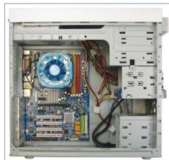
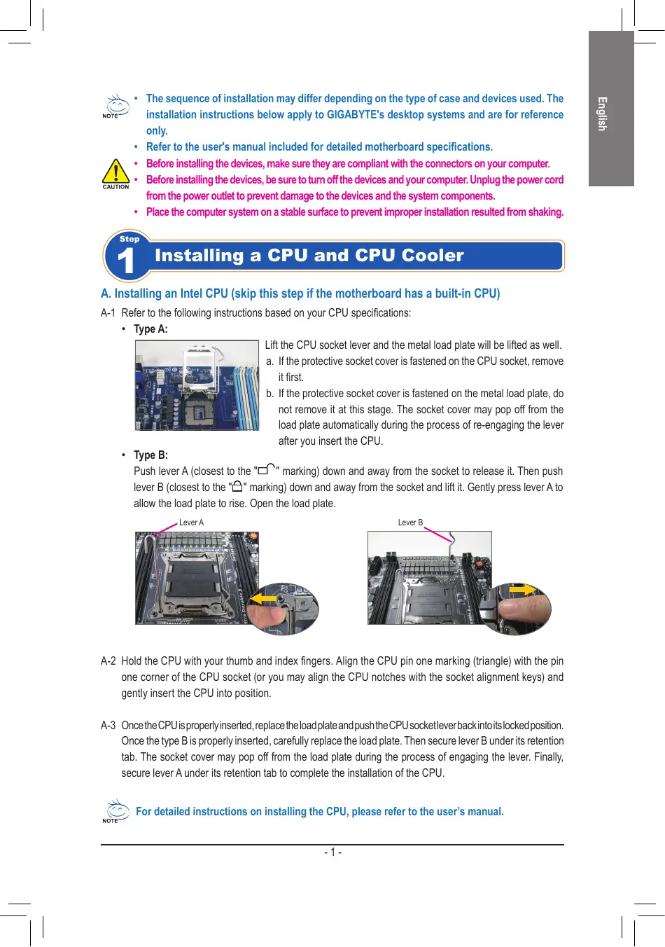
The sequence of installation may differ depending on the type of case and devices used. The installation instructions below apply to GIGABYTE's desktop systems and are for reference only.
Refer to the user's manual included for detailed motherboard specifications.
- Before installing the devices, make sure they are compliant with the connectors on your computer.
- Before installing the devices, be sure to turn off the devices and your computer. Unplug the power cord from the power outlet to prevent damage to the devices and the system components.
- Place the computer system on a stable surface to prevent improper installation resulted from shaking.

GIGABYTE GA-970A-DS3P - 1

Installing a CPU and CPU Cooler

A. Installing an Intel CPU (skip this step if the motherboard has a built-in CPU)

A-1 Refer to the following instructions based on your CPU specifications:
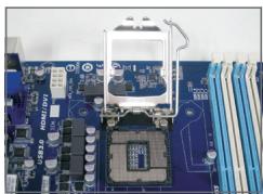
  • Type A:

GIGABYTE GA-970A-DS3P - Installing an Intel CPU (skip this step if the motherboard has a built-in CPU) - 1

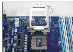
Lift the CPU socket lever and the metal load plate will be lifted as well.

a. If the protective socket cover is fastened on the CPU socket, remove it first.
b. If the protective socket cover is fastened on the metal load plate, do not remove it at this stage. The socket cover may pop off from the load plate automatically during the process of re-engaging the lever after you insert the CPU.

  • Type B:

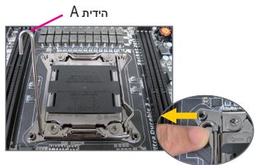
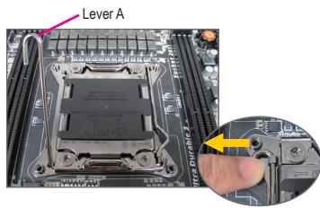
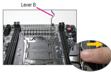
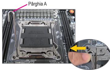
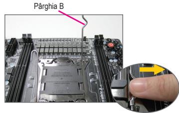
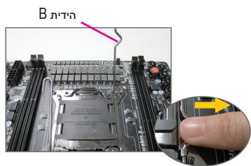
Push lever A (closest to the "□" marking) down and away from the socket to release it. Then push lever B (closest to the "□" marking) down and away from the socket and lift it. Gently press lever A to allow the load plate to rise. Open the load plate.
GIGABYTE GA-970A-DS3P - Installing an Intel CPU (skip this step if the motherboard has a built-in CPU) - 2

GIGABYTE GA-970A-DS3P - Installing an Intel CPU (skip this step if the motherboard has a built-in CPU) - 3

A-2 Hold the CPU with your thumb and index fingers. Align the CPU pin one marking (triangle) with the pin one corner of the CPU socket (or you may align the CPU notches with the socket alignment keys) and gently insert the CPU into position.
A-3 Once the CPU is properly inserted, replace the load plate and push the CPU socket lever back into its locked position. Once the type B is properly inserted, carefully replace the load plate. Then secure lever B under its retention tab. The socket cover may pop off from the load plate during the process of engaging the lever. Finally, secure lever A under its retention tab to complete the installation of the CPU.

GIGABYTE GA-970A-DS3P - Installing an Intel CPU (skip this step if the motherboard has a built-in CPU) - 4

For detailed instructions on installing the CPU, please refer to the user's manual.

B. Installing an AMD CPU (skip this step if the motherboard has a built-in CPU)

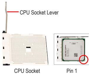
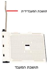
B-1 Completely raise the CPU socket lever. Align the CPU pin one (small triangle marking) with the triangle marking on the CPU socket and gently insert the CPU into the socket. Make sure that the CPU pins fit perfectly into their holes.
B-2 Once the CPU is positioned into its socket, place one finger down on the middle of the CPU, lowering the socket lever and latching it into the fully locked position.
GIGABYTE GA-970A-DS3P - Installing an AMD CPU (skip this step if the motherboard has a built-in CPU) - 1

GIGABYTE GA-970A-DS3P - Installing an AMD CPU (skip this step if the motherboard has a built-in CPU) - 2

  • Do not force the CPU into the CPU socket. The CPU cannot fit in if oriented incorrectly. Adjust the CPU orientation if this occurs.
  • DO NOT touch socket contacts. To protect the CPU socket, always replace the protective socket cover when the CPU is not installed.

C. Installing the CPU cooler
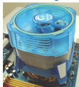
GIGABYTE GA-970A-DS3P - Installing the CPU cooler - 1

GIGABYTE GA-970A-DS3P - Installing the CPU cooler - 2

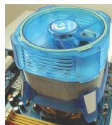
C-1 Before installing the CPU cooler, please first add a thin layer of heat sink paste on the surface of the CPU. Then install the cooler (refer to the installation manual for your CPU cooler).
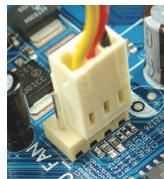
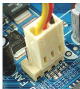
C-2 Connect the CPU cooler cable to the CPU_FAN connector located on the motherboard so that the cooler can properly function to prevent the CPU from overheating.

GIGABYTE GA-970A-DS3P - Installing the CPU cooler - 3

Installing Memory

GIGABYTE GA-970A-DS3P - Installing Memory - 1

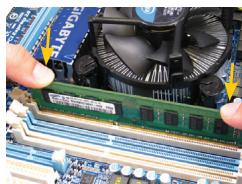
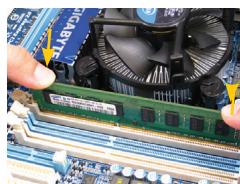
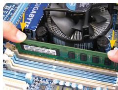
Note the orientation of the memory module. Spread the retaining clips at both ends of the memory socket. Place the memory module on the socket. As indicated in the picture on the left, place your fingers on the top edge of the memory, push down on the memory and insert it vertically into the memory socket. The clips at both ends of the socket will snap into place when the memory module is securely inserted.

GIGABYTE GA-970A-DS3P - Installing Memory - 2

Preparing the Case and Installing a Power Supply
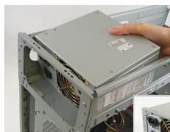
GIGABYTE GA-970A-DS3P - Preparing the Case and Installing a Power Supply - 1
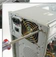
GIGABYTE GA-970A-DS3P - Preparing the Case and Installing a Power Supply - 2

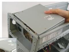
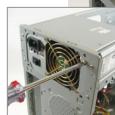
Using the GIGABYTE desktop system as the demonstration example, please first remove both sides and the lid of the case in order to install the power supply. Place the power supply in the correct place in the case and secure it with screws. Installation and placement of the power supply may differ depending on the type of case used.

GIGABYTE GA-970A-DS3P - Preparing the Case and Installing a Power Supply - 3

To ensure sufficient power can be supplied to your system, it is recommended that a power supply of good quality be used. If a power supply is used that does not provide the required power, the result can lead to an unstable or unbootable system.

Step

4

Installing the Motherboard
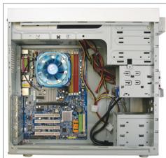
GIGABYTE GA-970A-DS3P - Installing the Motherboard - 1

Remove the original I/O shield from the back of the case and replace it with the motherboard I/O shield. Place the motherboard within the case by positioning it into its I/O shield. Align the mounting screw holes on the motherboard with their corresponding mounting holes on the case. Secure the motherboard in place with screws.
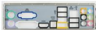
GIGABYTE GA-970A-DS3P - Installing the Motherboard - 2

I/O Shield

Step

5

Installing an Expansion Card
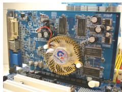
GIGABYTE GA-970A-DS3P - Installing an Expansion Card - 1
PCI Express Graphics Card

Locate an expansion slot that supports your card and remove the slot cover from the case back panel. Then insert the expansion card into the slot. Secure the expansion card's bracket to the case back panel with a screw.

GIGABYTE GA-970A-DS3P - Installing an Expansion Card - 2

  • Before purchasing an expansion card, check the length of the card, making sure it can fit into your case.
  • Make sure that the expansion card is fully seated in its slot.

Step

6

Installing IDE and SATA Devices
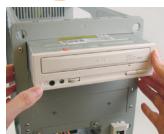
GIGABYTE GA-970A-DS3P - Installing IDE and SATA Devices - 1
Installing an Optical Drive

6-1 Install your optical drives, such as DVD-ROM and CD-ROM drives.

Remove the 5.25" drive bay cover from the front of the case. Mount the optical drive in the 5.25" drive bay and secure it with screws.
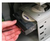
GIGABYTE GA-970A-DS3P - Installing IDE and SATA Devices - 2
Installing a Hard Drive

6-2 Install your IDE and SATA hard drives.

Install the hard drive into a drive bay within the case and secure it with screws.

GIGABYTE GA-970A-DS3P - Installing IDE and SATA Devices - 3

  • One motherboard IDE connector can connect up to two IDE devices. Prior to installation, check the jumper settings (master and slave) on your IDE devices.
  • If more than one hard drive is installed, enter system BIOS Setup to set the hard drive boot sequence.

GIGABYTE GA-970A-DS3P - Installing IDE and SATA Devices - 4

Connecting Cables to Internal Connectors

7-1 Connect cables to internal connectors and headers on the motherboard, including IDE/SATA connectors, and front panel audio, USB, IEEE 1394 headers, etc.
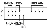
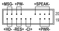
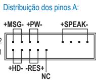
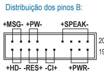
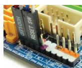
7-2 Attach the front panel module (differs depending on the case design, consisting of power indicator, hard drive activity indicator, speakers, reset switch, power switch, etc.) from the case to the front panel header (F PANEL) on the motherboard.
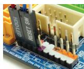
GIGABYTE GA-970A-DS3P - Connecting Cables to Internal Connectors - 1
Front Panel Header

GIGABYTE GA-970A-DS3P - Connecting Cables to Internal Connectors - 2
Pin Assignments A:

GIGABYTE GA-970A-DS3P - Connecting Cables to Internal Connectors - 3
Pin Assignments B:
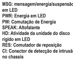
MSG: Message/Power/Sleep LED

PWR: Power LED

PW: Power Switch

SPEAK:Speaker

HD: Hard Drive Activity LED

RES: Reset Switch

Cl: Chassis Intrusion Header

(Note) The pin assignments for the front panel header may differ by model. Refer to the motherboard user's manual for the actual pin assignments.

GIGABYTE GA-970A-DS3P - Connecting Cables to Internal Connectors - 4

Connecting Peripherals

GIGABYTE GA-970A-DS3P - Connecting Peripherals - 1
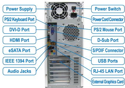
Back Panel of the Case

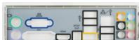
Once the steps above have been completed, connect the peripheral devices to the computer, such as the keyboard, mouse, monitor, etc. Then connect the power, turn on the system, and install all required software.

GIGABYTE GA-970A-DS3P - Connecting Peripherals - 2

GIGABYTE GA-970A-DS3P - Connecting Peripherals - 3
Conector do paine frontal

GIGABYTE GA-970A-DS3P - Connecting Peripherals - 4

GIGABYTE GA-970A-DS3P - Connecting Peripherals - 5

GIGABYTE GA-970A-DS3P - Connecting Peripherals - 6

YctaHOBka CNCTeMHoN pIaTbI

GIGABYTE GA-970A-DS3P - YctaHOBka CNCTeMHoN pIaTbI - 1

CnHmnte 3aIyUkPy pa3bEmOB BBOda/BbIBOda Ha 3aIeHne HaneHn Kopnyca n yCTAHOBITE Ha ee MeTO NaHEnb pa3bEmOB BBOda/BbIBOda nKOMNIJEKTa noCTABKN CNTeMHNO nPaTb. YCTAHOBITE CNTeMHYIO nPATEB KOPnyce, COBMecTINB pa3bEmbl Ha 3aIeHne HaneHn CNCTeMHNO nPATE C OTBepCTNnMn H aNaHEn BBOda/BbIBOda. COBMecTIne KpeENXhIE OTBepCTNc NCTeMHNO nPATAc CCOBTETCBYUQIMN OTBepCTNnMn Kopnyca. 3akpenite CNTeMHYIO nPATy B Kopnyce PI K c NOMouBv BNTOB.
GIGABYTE GA-970A-DS3P - YctaHOBka CNCTeMHoN pIaTbI - 2

3aŋnyuka pa3bEmOB BBOda/BbBOda

GIGABYTE GA-970A-DS3P - YctaHOBka CNCTeMHoN pIaTbI - 3

YctaHOBka pnaTbI paCwnpeHnA

Adum Bellegin Kurulumu
GIGABYTE GA-970A-DS3P - Adum Bellegin Kurulumu - 1

Push lever A (closest to the "□" marking) down and away from the socket to release it. Then push lever B (closest to the "□" marking) down and away from the socket and lift it. Gently press lever A to allow the load plate to rise. Open the load plate.
GIGABYTE GA-970A-DS3P - Adum Bellegin Kurulumu - 2

GIGABYTE GA-970A-DS3P - Adum Bellegin Kurulumu - 3

A-2 Hold the CPU with your thumb and index fingers. Align the CPU pin one marking (triangle) with the pin one corner of the CPU socket (or you may align the CPU notches with the socket alignment keys) and gently insert the CPU into position.
A-3 O data ce CPU-ul este introdus corect, asezati din nou placuţa de metal si impingeti bratul sociului de CPU inapo in positia blocata.

PWR: LED pornography

PW: Intrerupātār de alimentare

SPEAK: Difuzor

HD:LED activate hard disk

RES: Intrerupator de reinitializare

IDE-n npnn (Jumper) (slave-master)

wnn BIOs-nnnn nn nnnn nn nnnn nn

GIGABYTE GA-970A-DS3P - Adum Bellegin Kurulumu - 4
.

(wnnnn nn nnnn nn nnnn nn nnnn nn nnnn nn nnnn nn
GIGABYTE GA-970A-DS3P - (wnnnn nn nnnn nn nnnn nn nnnn nn nnnn nn nnnn nn - 1

GIGABYTE GA-970A-DS3P - (wnnnn nn nnnn nn nnnn nn nnnn nn nnnn nn nnnn nn - 2

TAYAN WNN'ON 19 NNN. TAYAN NNN INN NNN PINK ON 1-2
OON, TAYAN NNN BY IIONN WNN INN INN (IINW NNN)
PNNN TAYAN WNN INN INN INN

0000000000000000

n, Twn nn nnn nn nn nn nn nn nn nn nn nn nn nn nn nn nn nn nn nn nn nn nn nn nn nn nn nn nn nn nn nn nn nn nn nn nn nn nn nn nn nn nn nn nn nn nn nn nn nn nn nn nn nn nn nn nn nn nn nn nn nn nn nn nn nn nn nn nn nn nn nn nn nn nn nn nn nn nn nn nn nn nn nn nn nn nn nn nn nn nn nn nn nn nn nn nn nn nn nn nn nn nn

nnp nnp npnnn nn nnnnnnnnnnnnnnnnnnnnnnnnnnnnnnnnnnnnnnnnnnnnn

.

GIGABYTE GA-970A-DS3P - (wnnnn nn nnnn nn nnnn nn nnnn nn nnnn nn nnnn nn - 3

n nn nnnnnnnnnnnnnnnnnnnnnnnnnnnnnnnnnnnnnnnnnnnnnnnnnnnnnnnnnnnnnnnnnnnnnnnnnnnnnnnnnnnnnnnnnnnnnnnnn

Taynn npn .

y nnnn nn nnnn nn nnn nnn nnnn nnnn nnnn nnnn nnnn nnnn nnnn nnnn nnnn nnnn nnnn nnnn nnnn nnnn nnnn nnnn nnnn nnnn nnnn nnnn nnnn nnnn nnnn nnnn nnnn nnnn nnnn nnnn nnnn nnnn nnnn nnnn nnnn nnnn nn

PCN PNNN NNNN NNNN NNNN NNNN NNNN NNNN NNNN NNNN NNNN NNNN NNNN NNNN NNNN NNNN NNNN NNNN NNNN NNNN NNNN NNNN NNNN NNNN NNNN NNNN NNNN NNNN NNNN NNNN NNNN NNNN NNNN NNNN NNNN N

1-
GIGABYTE GA-970A-DS3P - Taynn npn . - 1

GIGABYTE GA-970A-DS3P - Taynn npn . - 2

GIGABYTE GA-970A-DS3P - Taynn npn . - 3

y

GIGABYTE GA-970A-DS3P - Taynn npn . - 4

nD 790 nnnn nn

3

n nn nnnnnnnnnnnnnnnnnnnnnnnnnnnnnnnnnnnnnnnnnnnnnnnnnnnnnnnnnnnnnnnnnnnnnnnnnnnnnnnnnnnnnnnnnnnnnnnnnnnnnnnnnnnnnnnnnnn
GIGABYTE GA-970A-DS3P - nD 790 nnnn nn - 1

nnnnnnnnnnnnnnnnnnnnnnnnnnnnnnnnnnnnnnnnnnnnnnnnnnnnnnnnnnnnnnnnnnnnnnnnnnnnnnnnnnnnnnnnnnnnnnnnnnnnnnnnnnnnnnnnnnnnnnnnnnnnnnnnnnnnnnnnnnnnnnn

GIGABYTE GA-970A-DS3P - nD 790 nnnn nn - 2

GIGABYTE GA-970A-DS3P - nD 790 nnnn nn - 3

nni nnnn nn nnnn nnnn nnnn nnnn nnnn nnnn nnnn nnnn

.

.

wannnnn nn nnnn nn nnnnnnnnnnnnnnn

n nn nnnnnnnnnnnnnnnnnnnnnnnnnnnnnnnnnnnnnnnnnnnnnnn

nynnnnnnn

n nnnnnnnnnnnnnnnnnnnnnnnnnnnnn

GIGABYTE GA-970A-DS3P - nD 790 nnnn nn - 4

NOTE

GIGABYTE GA-970A-DS3P - nD 790 nnnn nn - 5

CAUTION

Taynn TAYNN

GIGABYTE GA-970A-DS3P - Taynn TAYNN - 1

(nnnn nn nnnnnnnnnnnnnnnnnnnnnnnnnnnnnnnnnnnnnnnnnnnnnnnnnnnnnnnnnnnnnnnnnnnnnnnnnnnnnnnnnnnnnnnnnnnnnnnnnnnnn

1

:A10

n nn nnnnnnnnnnnnnnnnnnnnnnn

ninn nixon,ynnn nwnn pnn nnwnn bnn 100 a.

wnn nn nnnnnnnnnnnnnnnnnnnnnnnnnnnnnnnnnnnnnnnnnnnnnnnnnnnnnnnnnnnnnnnnnnnnnnnnnnnnnnnnnnnnnnnnnnnnnnnnnnnnnnn

ywn nn nnnn nn nnnn nn nnnn nn nn nn nn nn

TNNNOONN
GIGABYTE GA-970A-DS3P - (nnnn nn nnnnnnnnnnnnnnnnnnnnnnnnnnnnnnnnnnnnnnnnnnnnnnnnnnnnnnnnnnnnnnnnnnnnnnnnnnnnnnnnnnnnnnnnnnnnnnnnnnnnn - 1

:Bao

Bnnn nnnnnnnnnnnnnnnnnnnnnnnnnnnnnnnnnnnnnnnnnnnnnnnnnnnnnnnnnnnnnnnnnnnnnnnnnnnnnnnnnnnnnnnnnnnnnnnnnnnnnnnnnnnnnnnnnnnnnnnnnnnnnnn

yipn nnh nx nn9.naiipnn nyipn
GIGABYTE GA-970A-DS3P - (nnnn nn nnnnnnnnnnnnnnnnnnnnnnnnnnnnnnnnnnnnnnnnnnnnnnnnnnnnnnnnnnnnnnnnnnnnnnnnnnnnnnnnnnnnnnnnnnnnnnnnnnnnn - 2

GIGABYTE GA-970A-DS3P - (nnnn nn nnnnnnnnnnnnnnnnnnnnnnnnnnnnnnnnnnnnnnnnnnnnnnnnnnnnnnnnnnnnnnnnnnnnnnnnnnnnnnnnnnnnnnnnnnnnnnnnnnnnn - 3

n nn nnnnnnnnnnnnnnnnnnnnnnnnnnnnnnnnnnnnnnnnnnnnnnnnnnnnnnnnnnnnnnnnnnnnnnnnnnnnnnnnnnnnnnnnnnnnnnnnnnnnnnnnnnnnnnnnnnnnnnnnnnnnnnnnnnnnnnnnnnn

B 1000000000000000000000000000000000000000000000000000000

.ynnnn

wnnnn nn nnnnnnnnnnnnnnnnnnnnnnnnnnnnnnnnnnnnnnnnnnnnnnnnnnnnnnnnnnnnnnnnnnnnnnnnnnnnnnnnnnnnnnnnnnnnnnnnnnnnnnnnn

GIGABYTE GA-970A-DS3P - (nnnn nn nnnnnnnnnnnnnnnnnnnnnnnnnnnnnnnnnnnnnnnnnnnnnnnnnnnnnnnnnnnnnnnnnnnnnnnnnnnnnnnnnnnnnnnnnnnnnnnnnnnnn - 4
Manual assistant
Powered by Anthropic
Waiting for your message
Product information

Brand : GIGABYTE

Model : GA-970A-DS3P

Category : Motherboard