
MP6590 - Exercise bike HMS Premium - Free user manual and instructions
Find the device manual for free MP6590 HMS Premium in PDF.


| Product Type | Exercise Bike |
| Brand | HMS Premium |
| Model | MP6590 |
| Dimensions (L x W x H) | Approx. 100 x 50 x 130 cm |
| Weight | Approx. 30 kg |
| User Weight Capacity | 120 kg |
| Power Supply | Battery (2x AAA) for display |
| Resistance System | Magnetic, manual adjustment |
| Resistance Levels | 8 levels |
| Display | LCD: time, speed, distance, calories, pulse |
| Programs | 12 preset programs |
| Heart Rate Monitoring | Hand pulse sensors |
| Pedals | Adjustable straps |
| Seat Adjustment | Vertical and horizontal |
| Handlebar Adjustment | Yes, multi-position |
| Transport Wheels | Yes |
| Leveling Feet | Yes, adjustable |
| Maintenance | Regular cleaning, lubricate moving parts |
| Safety | Emergency brake on resistance knob |
| Spare Parts Availability | Contact HMS customer service |
| Warranty | 2 years |
Frequently Asked Questions - MP6590 HMS Premium
User questions about MP6590 HMS Premium
0 question about this device. Answer the ones you know or ask your own.
Ask a new question about this device
Download the instructions for your Exercise bike in PDF format for free! Find your manual MP6590 - HMS Premium and take your electronic device back in hand. On this page are published all the documents necessary for the use of your device. MP6590 by HMS Premium.
USER MANUAL MP6590 HMS Premium
natural_image
Line drawing of an exercise bike with rotating wheel, arm, and exhaust pipe (no text or symbols)www.hms-fitness.pl

INSTRUKCJA MONTAŻU
Narzędzia:
Klucz S13-S17-S19
natural_image
Line drawing of a person in motion, no text or symbols presentROZCIĄGANIE MIĘŚNI ŁYDEK/ŚCIEGIEN ACHILLESA
Read all precautions and instructions in this manual before using this equipment.
BEFORE YOU BEGIN
Thank you for selecting brand HMS. For your safety and benefit, read this manual carefully before using the machine. As a manufacturer, we are committed to provide you complete customer satisfaction.
IMPORTANT SAFETY NOTICE
This product is intended only for home use and has been designed to ensure optimal safety. The following rules shall be obeyed:
- Before starting your workout, consult your physician to check if there are any reasons preventing the use of this fitness equipment. The doctor's decision is required if you take medicines that affect your heart work, blood pressure and levels of cholesterol. It is also necessary in the case of persons aged over 35 and people with health problems.
- Always do your warm-up before training.
- During exercise and after its completion the training equipment should be protected from children and animals.
-
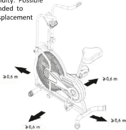
The equipment shall be placed on dry, stable and properly levelled surface. All sharp objects shall be removed from its direct vicinity. The equipment should be protected from humidity. Possible surface irregularities should be levelled. It is recommended to use special anti-slip base to prevent the equipment displacement during workout.
-
Free space should not be smaller than 0.6 m and greater. worrying signals. Incorrect or excessive exercising means headache or dizziness, chest pain, irregular heart rhythm symptoms appear during training, the workout shall be immediately and a doctor shall be consulted. Incorrect training can lead to traumas.
-
than the training space available in directions of the accessibility. Free space must also include space for If different pieces of equipment are located side by side, space can be divided.
-
Before the first use, and later at regular intervals, screws, bolts and other joints shall be checked.
-
Before starting your exercise, check fixing of parts and joints between them. Workout can be started only if the equipment is fully operational.
-
The equipment shall be regularly checked for wearing-out and damages. Only then will it fulfil safety requirements. Special attention shall be paid to foam grips, caps on legs and upholstery, which are all fast wearing parts. Damaged parts shall be immediately repaired or replaced. Until then, the training equipment cannot be used.
-
Do not put any elements into openings.
-
Pay attention to protruding adjustment devices and other structural elements that might hinder exercise.
-
The equipment can only be used according to its intended purpose. If any parts wears out or is damaged, or if you hear worrying sounds when using the equipment, you should immediately stop exercising. Do not use the equipment again until the problem is removed.
-
Wear comfortable clothes and sport shoes for training. Avoid loose clothes that might catch protruding parts of the equipment or limit your mobility.
-
The equipment falls into class H according to standard EN ISO 20957-1 and is intended for home use only. It cannot serve therapeutic, rehab or commercial purposes.
-
When lifting or moving the equipment, maintain correct posture to avoid spine injuries.
-
The product is intended for adults only. Keep children without supervision away from the equipment.
-
During installation, follow closely the attached manual instruction and use only such parts that have been included in the package. Before installation, check if all parts from the list are included in the package.
Pay attention to health hazard. If or other worrying stopped or over-intensive
equipment emergency quitting. the size of free
tightness of all
Technical data:
Max user weight: 110 kg
Net weight: 30 kg; Gross weight: 32 kg Dimensions – 923*613*1326 mm
WARNING: READ THE INSTRUCTION BEFORE USING THE EQUIPMENT.

WE ARE NOT RESPONSIBLE FOR INJURIES OR DAMAGES TO OBJECTS CAUSED BY INCORRECT USE OF THE PRODUCT
MAINTENANCE: No aggressive cleaning agents shall be used to clean the equipment. Use a soft, wet cloth to remove dirt and dust.
The equipment shall be kept in dry places and protected from humidity and corrosion.
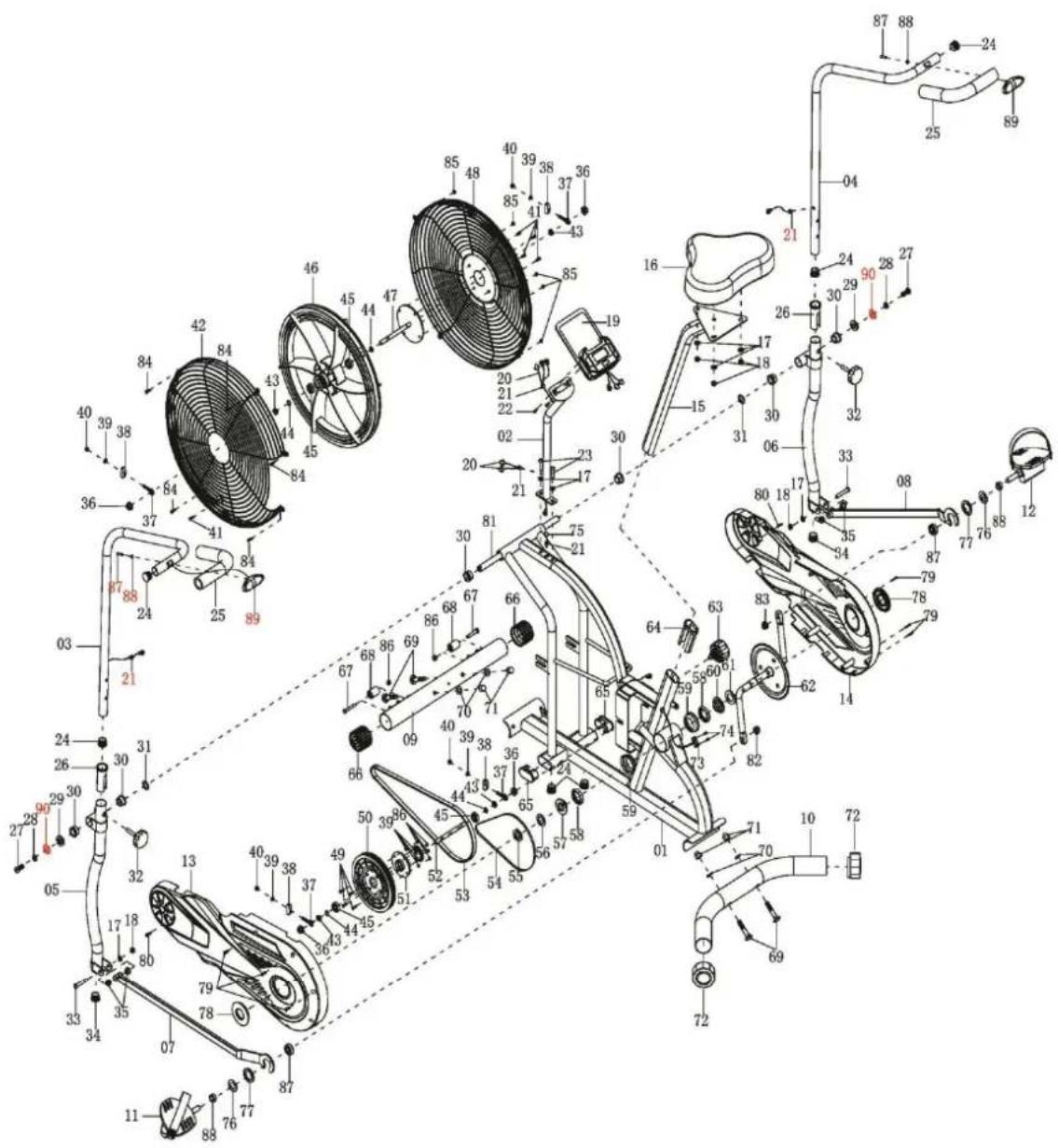
| No. | Description | Qty | No. | Description | Qty |
| 01 | Main Frame | 1 | 32 | Handrail Arm Adjustable Knob M8 | 2 |
| 02 | Computer Post | 1 | 33 | Hexagon Bolt M8×48 | 2 |
| 03 | Left Handrail Arm | 1 | 34 | Plug ∅ 32 | 2 |
| 04 | Right Handrail Arm | 1 | 35 | Spacer Bushing∅ 18×∅ 14×∅ 8×10 | 4 |
| 05 | Left Handrail | 1 | 36 | Flange Nut M10×P1.0 | 4 |
| 06 | Right Handrail | 1 | 37 | Eyebolt M6×36 | 4 |
| 07 | Left Foot Bar | 1 | 38 | U-shape Bracket | 4 |
| 08 | Right Foot Bar | 1 | 39 | Spring Washer ∅ 6 | 8 |
| 09 | Front Stabilizer ∅50 | 1 | 40 | Nut M6 | 4 |
| 10 | Rear Stabilizer ∅50 | 1 | 41 | Cross Pan Head Screw M6×10 | 5 |
| 11 | Left Foot Pedal | 1 | 42 | Left Cover for Flywheel ∅ 490 | 1 |
| 12 | Left Foot Pedal | 1 | 43 | Hexagon Nut M10×P1×5 | 4 |
| 13 | Left Cover | 1 | 44 | Circlip Φ10 | 4 |
| 14 | Right Cover | 1 | 45 | Bearing 6000Z | 4 |
| 15 | Seat Post | 1 | 46 | Flywheel ∅ 415×55 | 1 |
| 16 | Seat Cushion | 1 | 47 | Axle Sleeve | 1 |
| 17 | Flat Washer ∅8×∅16×1.5 | 7 | 48 | Right Cover for Flywheel ∅ 490 | 1 |
| 18 | Nylon Nut M8 | 5 | 49 | Hexagon Bolt M6×15 | 4 |
| 19 | Computer | 1 | 50 | Belt Pulley with crank ∅ 170 | 1 |
| 20 | Extension Sensor Wire L=450mm | 3 | 51 | Gear | 1 |
| 21 | Wire Plug ∅ 12 | 5 | 52 | Axle Φ10×140 | 1 |
| 22 | Cross Pan Head Screw M5×10 | 2 | 53 | Belt PJ390/J5 | 1 |
| 23 | Hexagon Bolt M8×30 | 2 | 54 | Chain | 1 |
| 24 | Handrail Arm End Cap ∅25 | 6 | 55 | Hexagon Flat Nut 7/8" | 1 |
| 25 | Handrail Arm Foam Grip∅ 24×∅ 35×280 | 2 | 56 | Washer ∅ 35×2 | 1 |
| 26 | Plastic Bushing ∅ 32×1.5 | 2 | 57 | Puller Bushing 15/16" | 1 |
| 27 | Hexagon Bolt M10×20 | 2 | 58 | Bearing Φ44.5 | 2 |
| 28 | Spring Washer∅ 19.5×∅11.5×2.5 | 2 | 59 | Bearing Bush ∅ 55.6×16 | 2 |
| 29 | Washer ∅ 28×∅ 16×δ5 | 2 | 60 | Puller Bushing 7/8" | 1 |
| 30 | Bushing ∅ 28×∅ 16×16 | 8 | 61 | Flat Washer ∅ 40×2.8 | 1 |
| 31 | Wave Washer ∅ 26×∅ 16×δ0.3 | 2 | 62 | Chain Pulley with Crank ∅ 165 | 1 |
| 63 | Seat Height Adjustable Knob M16 | 1 | 78 | Crank Cover ∅ 60 | 2 |
| 64 | Seat Post Plastic Bushing50×25×1.5 | 1 | 79 | Cross Pan Head Tapping ScrewST4.2×20 | 6 |
| 65 | End Cap for Main Frame | 2 | 80 | Cross Countersunk HeadTapping Screw ST4.2×20 | 2 |
| 66 | End Cap for Front Stabilizer ∅ 50 | 2 | 81 | Rotation Rod | 1 |
| 67 | Hexagonal Bolt M6×45 | 2 | 82 | Left Nylon Nut | 1 |
| 68 | Movable Wheel∅ 22×∅ 6.5×30.5 | 2 | 83 | Right Nylon Nut | 1 |
| 69 | Bolt M10×56 | 4 | 84 | Cross Pan Head ScrewM5×10 | 5 |
| 70 | Curve Washer ∅ 10×∅ 20×2.0 | 4 | 85 | Nylon Nut M5 | 5 |
| 71 | Cap Nut M10 | 4 | 86 | Nylon Nut M6 | 6 |
| 72 | End Cap for Rear Stabilizer ∅ 50 | 2 | 87 | Cross Countersunk Head Self-drillingTapping Screw ST4.2×20 | 2 |
| 73 | Sensor L=350mm | 1 | 88 | Flat Washer ∅ 5×∅9×0.8 | 2 |
| 74 | Cross Pan Head Self-tappingScrew ST2.9×9.5 | 2 | 89 | Handpulse Sensor with WireL=1100mm | 2 |
| 75 | Sensor Wire L=500mm | 1 | 90 | Flat Washer ∅ 10×∅25×2.0 | 1 |
| 76 | Washer ∅ 24×∅ 13×4.0 | 2 | |||
| 77 | Bushing ∅ 16×∅ 13×14.5 | 2 |
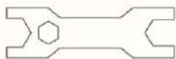
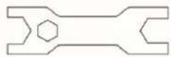
Spanner S13-S17-S19
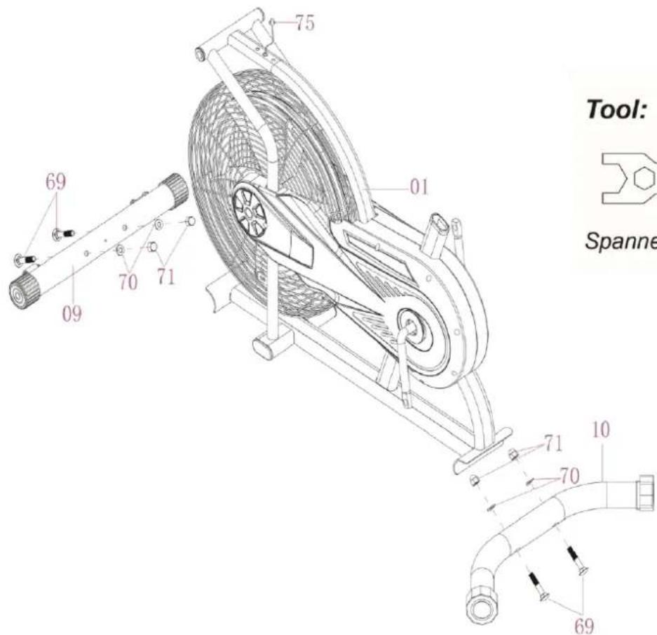
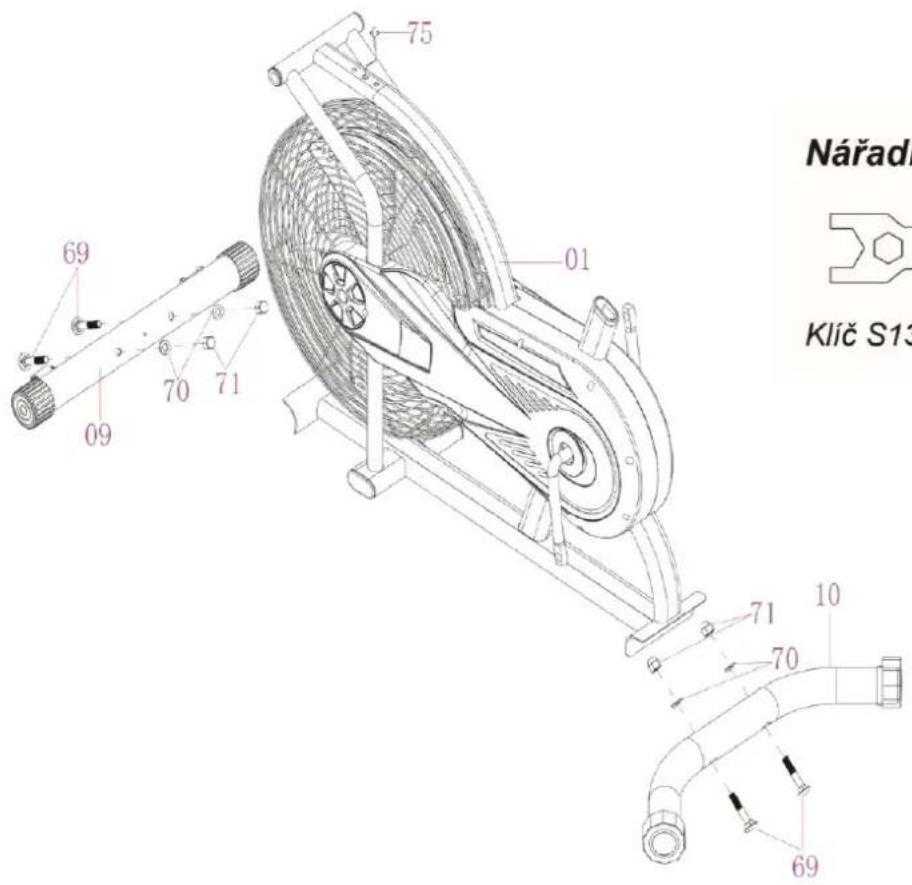
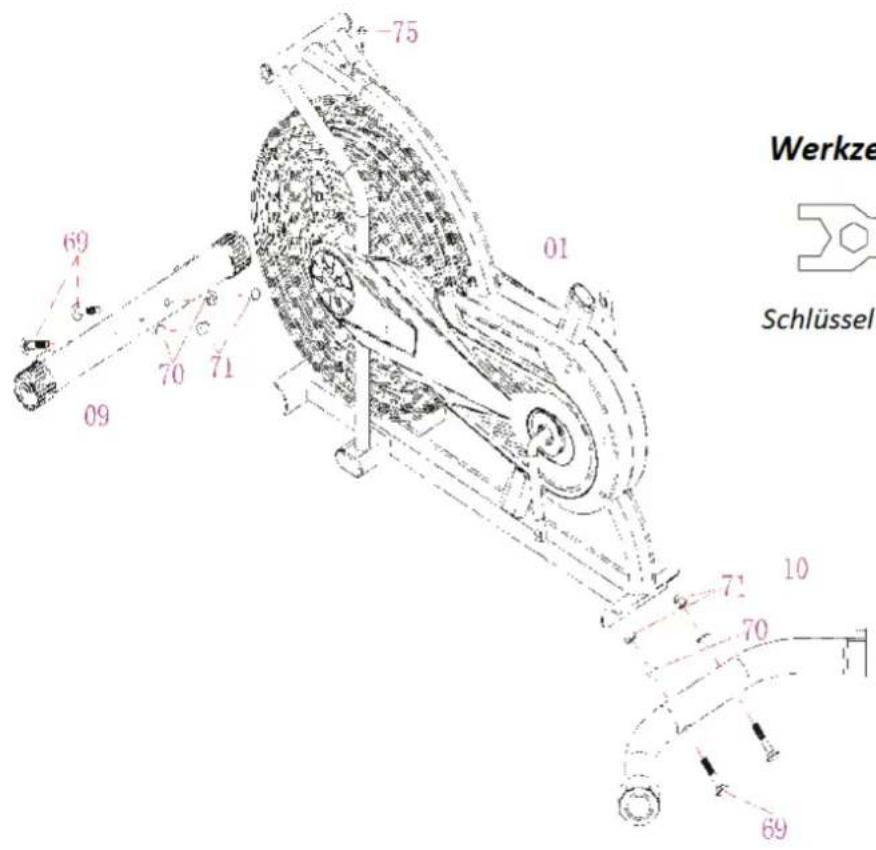
1. Front and Rear Stabilizers Installation
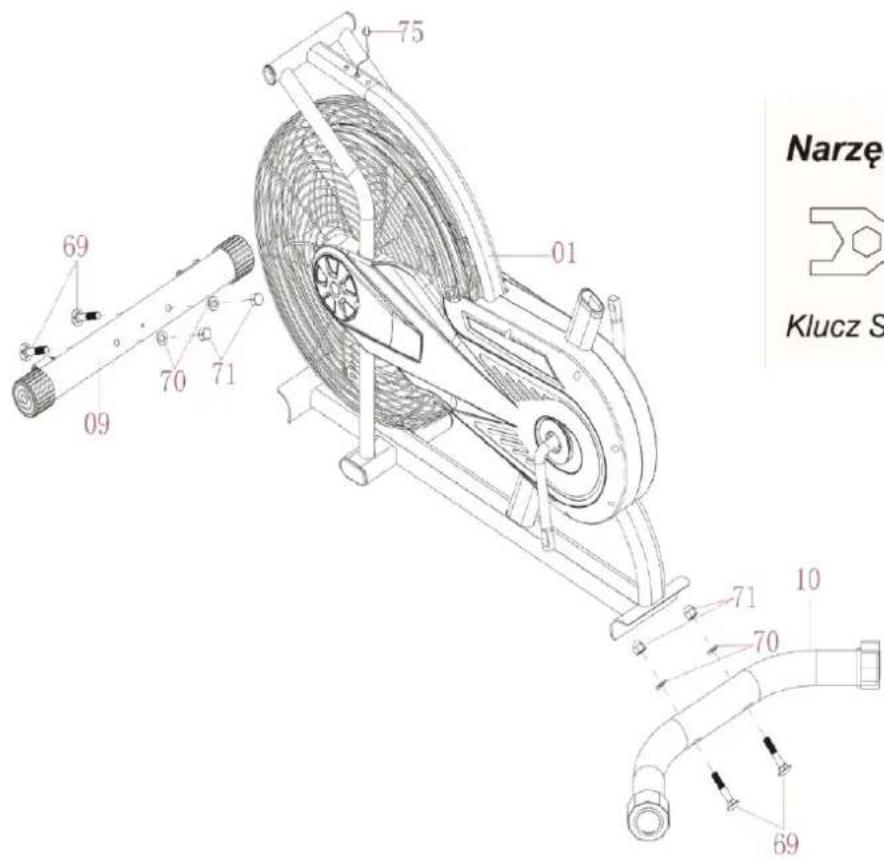
Attach the Rear Stabilizer (10) onto the Main Frame (1) with two M10 Cap Nuts (71), two 10× 20×2.0 Curve Washers (70) and two M10×56 Bolts (69). Tighten with the Spanner provided.
Attach the Front Stabilizer (9) onto the Main Frame (1) using two M10 Cap Nuts (71), two 10× 20×2.0 Curve Washers (70) and two M10×56 Bolts (69). Tighten with the Spanner provided.
Tool:
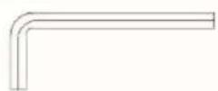
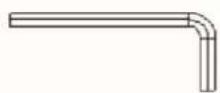
Allen Wrench S6
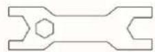
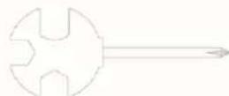
Spanner S13-S17-S19
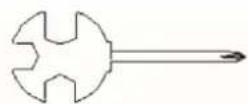
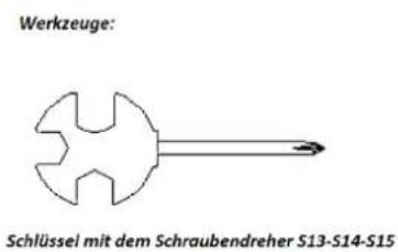
Spanner with Phillips Screwdriver S13-S14-S15
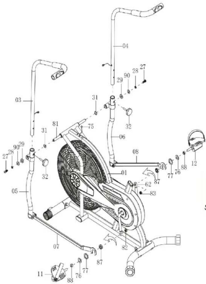
2. Left and Right Foot Pedals, Left and Right Foot Bar, Left and Right
Handrail Arm Installation
Remove two M10×20 Hexagon Bolts (27), two ∅ 19.5×∅11.5×2.5 Spring Washers (28), two ∅ 10×∅25×2.0 Flat Washer, two ∅28×∅ 16×δ5 Washers (29), and two ∅ 26×∅ 16×δ0.3 Wave Washers (31) from the Rotation Rod (No. 81). Insert the Rotation Rod (81) into the hole of the Main Frame (1). Attach two ∅ 26×∅ 16×δ0.3 Wave Washers (31) onto the Rotation Rod (81), then attach L & R Handrails (5)(6) onto the Rotation Rod (81) using two M10×20 Hexagon Bolts (27), two ∅ 19.5×∅11.5×2.5 Spring Washers (28) and Two ∅ 28×∅ 16×δ5 Washers (No. 29). Tighten with Allen Wrench provided. Remove ∅ 24×∅ 13×4.0 Washer (76), 16×∅ 13×14.5 Bushing (77) and Right Nylon Nut (83) from the Right Foot Pedal (12). Attach the Right Foot Pedal (12) onto the right Crank (62) using ∅ 24×∅ 13×4.0 Washer (76), ∅ 16×∅ 13×14.5 Bushing (77), Right Foot Bar (8) and Right Nylon Nut (83). Tighten the Right Foot Pedal (12) by hand clockwise and tighten the Right Nylon Nut (83) counter-clockwise with Allen Wrench and Spanner provided. Repeat the same procedure to attach the Left Foot Pedal (11) onto the left Crank, tighten the Left Foot Pedal (11) counter-clockwise and tighten the Left Nylon Nut (82) clockwise with Allen Wrench and Spanner provided.
Do not turn the Left pedal clockwise to tighten or will strip the threads.
Insert the Right Handrail Arm (4) into the Plastic Bushing on the tube of the Right Handrail (6) using M8 Handrail Arm Adjustable Knob (32).
Repeat the same procedure to assemble the Left Handrail Arm (3).
Tool:
natural_image
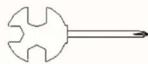
Simple line drawing of a hammer and sickle (no text or symbols)Spanner with Phillips
Screwdriver S13-S14-S15
3. Seat Post, Seat Cushion Installation
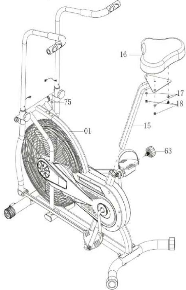
Remove three 8×16×1.5 Flat Washers (17) and three M8 Nylon Nuts (18) from under the Seat Cushion (16). Attach the Seat Post (15) to the Seat Cushion (16) using three 8×16×1.5 Flat Washers (17) and three M8 Nylon Nuts (18). Tighten with the Spanner with Phillips Screwdriver provided.
Insert the Seat Post (15) into the Seat Post Plastic Bushing on the tube of the Main Frame (1) and then attach the M16 Seat Height Adjustable Knob (63) onto the tube of the Main Frame (1) by turning it in a clockwise direction to lock the Seat Post (15) in the suitable position.
Adjusting the Seat Height
Turn the M12 Seat Height Adjustable Knob (63) in a counterclockwise direction to release the Seat Post (15) and then slide the Seat Post (15) up or down slightly to the desired hole for the suitable position. Lock the Seat Post (15) in place by tightening the M12 Seat Height Adjustable Knob (63) in a clockwise direction.
NOTE: When adjusting the height of seat post, make sure the seat post plastic bushing does not exceed the mark line on the seat post.
Adjusting the Seat Back and Forth
Turn the M10 Knob (90) in a counterclockwise direction to release the Seat Slider (92). Then slide the Seat Slider (92) back or forth slightly to the desired hole for the suitable position. Lock the Seat Slider (92) in place by tightening the M10 Knob (90) in a clockwise direction.
Tool:
Allen Wrench S6
Spanner with Phillips Screwdriver
S13-S14-S15
4. Computer Post Installation
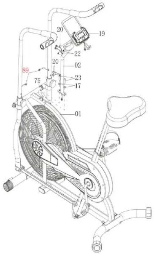
Connect the Sensor Wire (75) with Extension Sensor Wire (20).
Remove two 8×16×1.5 Flat Washers (17) and two M8×30 Hexagon Bolts (23) from the Main Frame (1).
Attach the Computer Post (2) onto the Main Frame (1) with two 8×16×1.5 Flat Washers (17) and two M8×30 Hexagon Bolts (23). Tighten with the S6 Allen Wrench provided.
Connect the Extension Sensor Wire (20) with the wire of the Computer (19).
Remove two M5×10 Cross Pan Head Screws (22) from the Computer (19).
Then attach the Computer (19) onto the top end of Computer Post (2) use two M5×10 Cross Pan Head Screws (22). Tighten with the Spanner with Phillips Screwdriver provided.
Functiona buttons:
MODE – Push down for selecting functions. If the long time holds down MODE button down for resetting time, distance and calories.
Functions and operations:
-
SCAN – press MODE buton until SCAN appears, monitor will rotate through al. 6 funtions: time, speed, distance, ODO, calories, pulse. Each display will be hold 5 seconds.
-
TIME – count the total time from the beginning of the workout to its end.
-
SPEED – display current speed.
-
DIST - count the distance from the beginning of the workout to its end.
-
CALORIES – count the total calories from the beginning of the workout to its end.
-
ODO - count the total distance of all workouts.
-
PULSE – put your hands od the pusle sensors, press the MODE buton. After about 6-7 seconds, the current heart rate will be displayed on the monitor.
| FUNCTION | AUTO SCAN | Every 5 seconds |
| TIME | 00:00'~99:59' | |
| CURRENT SPEED | The maximum signal can be pickup is 999.9(ML)KM/H | |
| TRIP DISTANCE | 0.0~9999 km | |
| CALORIES | 0.0~9999 kCal | |
| ODO | 0.0~9999 km | |
| PULSE RATE | 40~240 BPM | |
| BATTERY TYPE | 2 pcs of AAA lub UM -4 | |
During the process of pulse measurement, because of the contact jamming, the measurement value may be higher than the virtual pulse rate during the first 2\~3 seconds, then will return to normal level. The measurement value can not be regarded as the basis of medical treatment.
SPECIFICATION:
NOTE:
- If the display is faint of show no figures, please replace the batteries.
- The display will automatically turn off after 4 minutes of inactivity.
-
The monitor automatically starts as soon as you start training.
-
The computer automatically starts counting all values at the beginning of the exercise. After 4 seconds, the calculation will be discontinued.
| PROBLEM | SOLUTION |
| There is no display on the computer | 1. Remove the computer console and verify the wire that comes from the computer console is properly connected to the wire that comes from the handlebar post.2. Check if the batteries are correctly positioned and battery springs are in proper contact with batteries.3. The batteries in the computer consol |
| The bike wobbles when in use | Przekręć zaślepkę tylnego stabilizatora na tylnym stabilizatorze odpowiednio do poziomu rowerka. |
| The bike makes squeaking noise when in use. | Być może obluzowały się śruby. Sprawdź wszystkie śruby i dobręć obluzowane. |
The WARM-UP is an important part of any workout. The purpose of warming up is to prepare your body for exercise and to minimize injuries. Warm up for two to five minutes before aerobic exercising. It should begin every session to prepare your body for more strenuous exercise by heating up and stretching your muscles, increasing your circulation and pulse rate, and delivering more oxygen to your muscles.
COOL DOWN at the end of your workout, repeat these exercises to reduce soreness in tired muscles. The purpose of cooling down is to return the body to its resting state at the end of each exercise session. A proper cool-down slowly lowers your heart rate and allows blood to return to the heart.
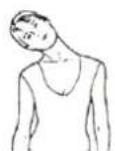
HEAD ROLLS
Rotate your head to the right for one count, you should feel a stretching sensation up the left side of your neck. Then rotate your head back for one count, stretching your chin to the ceiling and letting your mouth open. Rotate your head to the left for one count, then drop your head to your chest for one count.
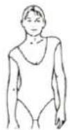
SHOULDER LIFTS
Lift your right shoulder toward your ear for one count. Then lift your left shoulder up for one count as you lower
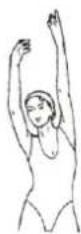
SIDE STRETCHES
Open your arms to the side and lift them until they are over your head. Reach your right arm as far toward the ceiling as you can for one count. Repeat this action with your left arm.

QUADRICEPS STRETCH
With one hand against a wall for balance, reach behind you and pull your right foot up. Bring your heel as close to your buttocks as possible. Hold for 15 counts and repeat with left foot.
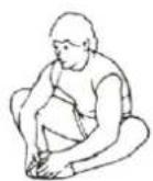
INNER THIGH STRETCH
Sit with the soles of your feet together and your knees pointing outward. Pull your feet as close to your groin as possible. Gently push your knees toward the floor. Hold for 15 counts.
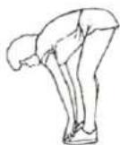
TOE TOUCHES
Slowly bend forward from your waist, letting your back and shoulders relax as you stretch toward your toes. Reach as far as you can and hold for 15 counts.
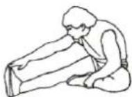
HAMSTRING STRETCHES
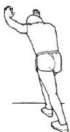
CALF/ACHILLES STRETCH
Extend your right leg. Rest the sole of your left foot against your right inner thigh. Stretch toward your toe as far as possible. Hold for 15 counts. Relax and then repeat with left leg.
Lean against a wall with your left leg in front of the right and your arms forward. Keep your right leg straight and the left foot on the floor; then bend the left leg and lean forward by moving your hips toward the wall. Hold, then repeat on the other side for 15 counts.
NEŽ ZAČNETE
MONTAGEANLEITUNG
Werkzeuge:
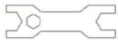
Schlüssel S13-S17-S19
Werkzeuge:
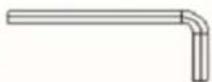
Imbusschlüssel S6
Schlüssel mit dem
-
The Seller provides guarantee on behalf of the Guarantor within the territory of the Republic of Poland for the period of 24 months from the date of sale: electric power assisted booster 24 months, charger 6 months.
-
The Guarantee will be recognised by the shop or service centre after the client provides:
- clearly and correctly filled-in guarantee card with the sale stamp and the seller's signature
- valid purchase confirmation for the equipment including the date of sale / bill, complained product.
-
Possible defects and damages revealed during the guarantee period shall be remedied free of charge within not more than 21 days from the delivery of the product to the shop or service.
-
Should it be necessary to import some components, the guarantee term can be extended by the period required to import such part, however such period shall not be longer than 90 days.
-
The guarantee does not cover:
- mechanical damages and subsequent defects,
- damages and defects resulting from incorrect storage and usage of the equipment against its purpose,
- incorrect assembly and maintenance,
- damages and consumption of such elements as: cables, straps, rubber parts, pedals, sponge grips, wheels, bearings, etc.
- The guarantee expires in the event of:
- expiry of the validity term,
- self-repairs,
- failure to follow the rules of correct operation.
-
The product handed over for repair should be complete and clean. If some parts are missing, the service is entitled to refuse to accept the product for repair. The service may refuse to accept a dirty product or clean in on the client's expense after the client's written permit.
-
The guarantee does not cover activities related to assembly, maintenance, which, according to the instruction, the user is obliged to perform themselves.
-
The Guarantor also informs that they offer post-guarantee service.
-
The product should be provided in its original packaging and should be secured for shipment.
-
To exercise the guarantee follow the procedure posted on the website: https://serwis.abisal.pl/
In case of non-conformity of the sold thing with the contract, the buyer is entitled by law to legal remedies from and at the expense of the seller. The guarantee does not affect such remedies.
THE EQUIPMENT IS NOT INTENDED FOR REHABILITATION AND THERAPY
NOTES ON THE COURSE OF REPAIRS
| Item | Date of notificacion | Date of provision | Course of repairs | Signature of the recipient (shop, owner) |
GARANTIEKARTE
Artikelname:
EAN-Code:
natural_image
Symbol of a trash bin crossed with no text or labels, representing waste sorting or disposal (no text present)natural_image
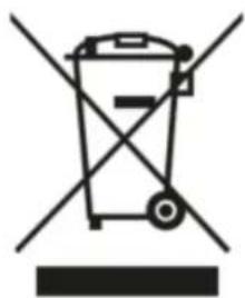
Symbol of a trash bin crossed with a diagonal line, no text or numbers presentMarking the equipment with a symbol of a crossed-out waste container informs about prohibition of placing used electrical and electronic equipment with other household waste. According to the WEEE Directive on used electrical and electronic waste management, separate disposal methods must be applied for this type of equipment.
A user, who intends to dispose this product, is required to deliver it to a collection point for used electrical and electronic equipment in order to contribute to reuse, recycling, or recovery and consequently, to protect the environment. To do this, contact the point where the device was purchased or local government officials. Hazardous components contained in the electronic equipment can cause long-lasting adverse changes in the environment, as well as have a harmful effect on human health.
natural_image
Symbol of a trash bin crossed with a diagonal line, no text or labels presentnatural_image
Symbol of a trash bin crossed out by two diagonal lines, no text or labels presentHMS-FITNESS.COM

IMPORTER: ABISAL SP. Z O.O., ul. Pyskowicka 17, 41-807 Zabrze, Polska
DISTRIBUTOR: ABISTORE SPORT S.R.O, U Cihelny 230/3, 74801 Hlučín, Česká Republika
abisal@abisal.pl www.abisal.pl
- www.hms-fitness.pl
- INSTRUKCJA MONTAŻU
- ROZCIĄGANIE MIĘŚNI ŁYDEK/ŚCIEGIEN ACHILLESA
- BEFORE YOU BEGIN
- IMPORTANT SAFETY NOTICE
- Front and Rear Stabilizers Installation
- Left and Right Foot Pedals, Left and Right Foot Bar, Left and Right
- Handrail Arm Installation
- Seat Post, Seat Cushion Installation
- Adjusting the Seat Height
- Adjusting the Seat Back and Forth
- Computer Post Installation
- Functiona buttons:
- Functions and operations:
- SPECIFICATION:
- NOTE:
- HEAD ROLLS
- SHOULDER LIFTS
- SIDE STRETCHES
- QUADRICEPS STRETCH
- INNER THIGH STRETCH
- TOE TOUCHES
- HAMSTRING STRETCHES
- CALF/ACHILLES STRETCH
- NEŽ ZAČNETE
- MONTAGEANLEITUNG
- THE EQUIPMENT IS NOT INTENDED FOR REHABILITATION AND THERAPY
- GARANTIEKARTE
Brand : HMS Premium
Model : MP6590
Category : Exercise bike