
EVI-D90N - Security Camera SONY - Free user manual and instructions
Find the device manual for free EVI-D90N SONY in PDF.


| Product Type | PTZ Security Camera |
| Image Sensor | 1/3-type CCD |
| Effective Pixels | 380,000 (NTSC/PAL) |
| Optical Zoom | 18x |
| Digital Zoom | 12x |
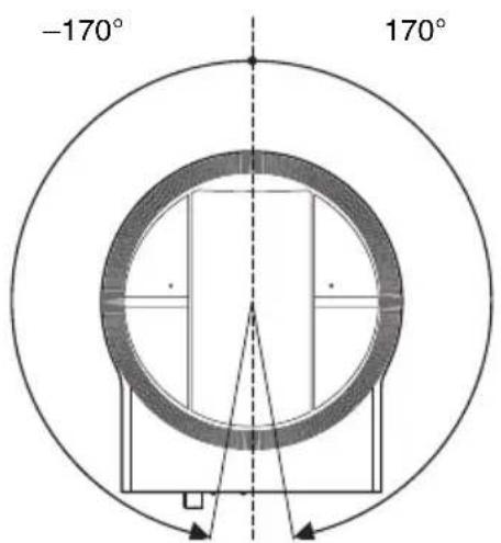
| Pan Range | ±170° |
| Tilt Range | -30° to +90° |
| Video Output | Composite (BNC), 1.0 Vp-p |
| Signal System | NTSC or PAL (switchable) |
| Minimum Illumination | 1.0 lux |
| Control Interface | RS-232C |
| Dimensions (WxHxD) | 132 x 144 x 144 mm |
| Weight | 1.5 kg |
| Power Supply | 12V DC |
| Power Consumption | 12 W |
| Operating Temperature | 0°C to 40°C |
| Mount Type | Ceiling or wall mount |
| Maintenance | Clean lens with soft, dry cloth |
| Safety | Use only specified power adapter |
| Spare Parts / Repairability | Contact Sony service center for parts |
Frequently Asked Questions - EVI-D90N SONY
User questions about EVI-D90N SONY
0 question about this device. Answer the ones you know or ask your own.
Ask a new question about this device
Download the instructions for your Security Camera in PDF format for free! Find your manual EVI-D90N - SONY and take your electronic device back in hand. On this page are published all the documents necessary for the use of your device. EVI-D90N by SONY.
USER MANUAL EVI-D90N SONY
Operating Instructions ____ GB
使用说明书 ____ CS
© 2011 Sony Corporation
4409059030
安全のために
natural_image
Technical line drawing of a mechanical component with a spherical top and flanged base (no text or symbols)natural_image
Line drawing of a rectangular electronic device with a coiled cable and connector (no text or symbols)電源コード(1)
natural_image
Line drawing of a cord with three leads, no text or symbols presentリモコン(RM-EV100)(1)
natural_image
Line drawing of a remote control device with buttons and dials (no text or symbols)シーリングブラケット (A) (1)
natural_image
Technical line drawing of a mechanical component with mounting holes and internal cavity (no text or symbols)シーリングブラケット (B) (1)
natural_image
Technical line drawing of a mechanical component with circular and rectangular features (no text or symbols)ワイヤーロープ (1)
natural_image
Line drawing of a coiled cable or wire with two endpoints (no text or symbols)natural_image
Simple line drawing of a screw with a central nut (no text or symbols)natural_image
Isometric line drawing of a multi-pin electrical connector (no text or symbols)取扱説明書(1)
各部の名称と働き
カメラ本体
前面
①レンズ
単 3 形乾電池 2 個(別売り)
電池の使用について
ご注意
ご注意
natural_image
Technical line drawing of a mechanical component with a dome-shaped top and textured base (no text or symbols)STANDBY 点滅
natural_image
Line drawing of a desktop computer setup with monitor, keyboard, mouse, and globe (no text or symbols)ご注意
natural_image
Illustration of hands holding a mechanical component with a cross mark, no text or symbols present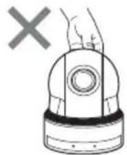
natural_image
Illustration of a hand holding a device with a cross symbol (no text or labels)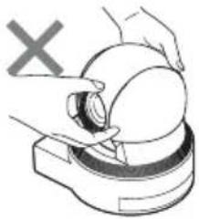
natural_image
Illustration of hands using a tool to clean or adjust a circular object, with a 'X' symbol indicating no text or labels.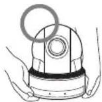
natural_image
Illustration of hands holding a mechanical device with a circular ring (no text or symbols)三脚に取り付ける
natural_image
Technical line drawing of a mechanical component with a circular base and mounting holes, showing a downward arrow indicating assembly or force (no text or symbols present)
| プリセットできる項目 プリセットポジション番号 | ||||||||||
| E | X | P | O | S | U | R | E | M | O | |
| SLOW SHUTTER | ||||||||||
| A | E | G | A | I | N | L | I | M | ||
| B | R | I | G | H | T | L | E | V | E | |
| S | P | E | E | D | ◎ | |||||
| I | R | I | S | ◎ | ○ | |||||
| G | A | I | N | ◎ | ○ | |||||
| E | X | - | C | O | M | P | O | N | / | |
| E | X | - | C | O | M | P | L | E | V | |
| W | H | I | T | E | B | A | L | A | N | |
| O | N | E | P | U | S | H | W | B | ||
| M | A | N | U | A | L | R | / | B | ||
| A | P | E | R | T | U | R | E | ◎ | ○ | |
| P | I | C | T | U | R | E | E | F | F | |
| H | I | G | H | R | E | S | O | L | U | |
| N | O | I | S | E | R | E | D | U | C | |
| W | I | D | E | D | * | |||||
| P | A | N | / | T | I | L | T | L | I | |
| D | - | Z | O | O | M | ◎ | ||||
| D | I | S | P | L | A | Y | I | N | F | |
- Focus Near Limit
- IR Receive
- IR Receive Return
映像信号 NTSC (EVI-D80N, EVI-D90N) PAL (EVI-D80P, EVI-D90P)
同期方式 内部同期方式
EVI-D90N/P : 10 mm (WIDE
端)~1500 mm (TELE 端) 外形寸法 300 mm (Default)
最低被写体照度
EVI-D80N/P: 0.4Lux 以下 / F1.4, 50 IRE
EVI-D90N/P: 0.65Lux 以下 / F1.35, 50 IRE
シャッタースピード
$$ 1 \sec \sim 1 / 1 0 0 0 0 \sec $$
映像 S/N 50 dB 以上
パン・チルト機能
水平± 170°
入出力端子
natural_image
Technical drawing of a circular mechanical component with 170° angular annotations (no text or symbols on the diagram itself)背面
正面 側面
底面
单位:mm
端子のピン配列
VISCA IN 端子
(8 ピンミニ DIN、凹)
VISCA IN
The model and serial numbers are located on the bottom. Record these numbers in the spaces provided below.
Refer to these numbers whenever you call upon your Sony dealer regarding this product.
Model No. Serial No.
WARNING
To reduce the risk of fire or electric shock, do not expose this apparatus to rain or moisture.
To avoid electrical shock, do not open the cabinet. Refer servicing to qualified personnel only.
WARNING
This unit has no power switch.
When installing the unit, incorporate a readily accessible disconnect device in the fixed wiring, or connect the power plug to an easily accessible socket-outlet near the unit. If a fault should occur during operation of the unit, operate the disconnect device to switch the power supply off, or disconnect the power plug.
IMPORTANT
The nameplate is located on the bottom.
For the customers in the U.S.A.
This equipment has been tested and found to comply with the limits for a Class A digital device, pursuant to part 15 of the FCC Rules. These limits are designed to provide reasonable protection against harmful interference when the equipment is operated in a commercial environment. This equipment generates, uses, and can radiate radio frequency energy and, if not installed and used in accordance with the instruction manual, may cause harmful interference to radio communications. Operation of this equipment in a residential area is likely to cause harmful interference in which case the user will be required to correct the interference at his own expense.
You are cautioned that any changes or modifications not expressly approved in this manual could void your authority to operate this equipment.
All interface cables used to connect peripherals must be shielded in order to comply with the limits for a digital device pursuant to Subpart B of part 15 of FCC Rules.
This device complies with part 15 of the FCC Rules. Operation is subject to the following two conditions: (1) This device may not cause harmful interference, and (2) this device must accept any interference received, including interference that may cause undesired operation.
For the customers in Canada
This Class A digital apparatus complies with Canadian ICES-003.
For the customers in Europe, Australia and New Zealand
WARNING
This is a Class A product. In a domestic environment, this product may cause radio interference in which case the user may be required to take adequate measures. In the case that interference should occur, consult your nearest authorized Sony service facility.
For the customers in Europe
The manufacturer of this product is Sony Corporation, 1-7-1 Konan, Minato-ku, Tokyo, Japan.
The Authorized Representative for EMC and product safety is Sony Deutschland GmbH, Hedelfinger Strasse 61, 70327 Stuttgart, Germany. For any service or guarantee matters please refer to the addresses given in separate service or guarantee documents.
This apparatus shall not be used in the residential area.
For the customers in the U.S.A. SONY LIMITED WARRANTY - Please visit http://www.sony.com/psa/warranty for important information and complete terms and conditions of Sony's limited warranty applicable to this product.
For the customers in Canada SONY LIMITED WARRANTY - Please visit http://www.sonybiz.ca/solutions/Support.do for important information and complete terms and conditions of Sony's limited warranty applicable to this product.
For the customers in Europe
Sony Professional Solutions Europe - Standard Warranty and Exceptions on Standard Warranty. Please visit http://www.pro.sony.eu/warranty for important information and complete terms and conditions.
For the customers in Korea SONY LIMITED WARRANTY - Please visit http://bpeng.sony.co.kr/handler/BPAS-Start for important information and complete terms and conditions of Sony's limited warranty applicable to this product.
AVERTISSEMENT
Phenomena Specific to CCD Image
Sensors ....57
Overview
Features 58
Supplied Accessories ....58
Location and Functions of Parts and
Controls 60
Camera 60
Remote Commander (supplied) ......62
Adjusting and Setting with Menus
About On-Screen Menus...... 65
Main Menu 65
Setting Menus ......65
Control Button Display Section ....65
Operating the Camera Using
Menus 66
EXPOSURE Menu 67
WHITE BALANCE Menu ......68
PICTURE Menu 69
PAN TILT ZOOM Menu ......69
SYSTEM Menu ....71
STATUS Menu 71
Operation Using the Supplied Remote Commander
Before Operating.... 72
Turning on the Power 72
Pan/Tilt and Zoom Operation .....73
Panning and Tilting 73
Zooming 74
Operating Multiple Cameras with the Remote
Commander 75
Adjusting the Camera 75
Focusing on a Subject 75
Shooting with Back Lighting ..... 75
Storing the Camera Settings in Memory
— the Presetting Feature ...... 76
Installation and Connection
Installing the Camera.... 78
Installing the Camera on a Desk 78
Attaching the Camera to a Tripod 78
Installing the unit on the ceiling 78
Installing the Camera Using the M3 Fixing Screw Holes ...... 82
Connections 82
Connecting to an AC Outlet ..... 82
Connecting a Computer 83
Connecting a video monitor or VTR equipped with a composite or S video input connector 84
Appendix
Message List.... 85
Troubleshooting.... 86
Menu Configuration 87
Preset Items 90
Specifications 92
Using the VISCA RS-422 connector pin assignments ...... 95
Precautions
Operating or storage location
Operating or storing the camera in the following locations may cause damage to the camera:
- Extremely hot or cold places (Operating temperature: 0^ to 40^ [32°F to 104°F])
- Exposed in direct sunlight for a long time, or close to heating equipment (e.g., near heaters)
- Close to sources of strong magnetism
- Close to sources of powerful electromagnetic radiation, such as radios or TV transmitters
- Locations subject to vibration or shock
Ventilation
To prevent heat buildup, do not block air circulation around the camera.
Transportation
When transporting the camera, repack it as originally packed at the factory or in materials equal in quality.
Cleaning the main unit
- When the body of the camera is dirty, clean it with a soft cloth that is soaked with a diluted neutral detergent and tightly wrung. Then finish with a dry cloth.
- Do not use any type of solvents, which may damage the finish.
- When you use a chemical cloth, follow its instructions.
- Do not sprinkle volatile matter such as pesticide over your camera nor allow rubber or vinyl to come in contact with the camera for a long period of time. Doing so may damage the finish.
Replacing the batteries of the Remote Commander
If the remote commander does not operate from a long distance, the batteries may be worn out. Replace the batteries with new ones (AA × 2).
Maintenance
The camera mechanism may cause abnormal noise due to wear and lubrication loss after a long period of use. To maintain optimum performance, we recommend periodical maintenance. If abnormal noise occurs, consult your Sony dealer.
Note on laser beams
Laser beams may damage the CCD image sensors. If you shoot a scene that includes a laser beam, be careful not to let a laser beam become directed into the image sensors of the camera.
Phenomena Specific to CCD Image Sensors
The following phenomena that may appear in images are specific to CCD (Charge Coupled Device) image sensors. They do not indicate malfunctions.
White flecks
Although the CCD image sensors are produced with high-precision technologies, fine white flecks may be generated on the screen in rare cases, caused by cosmic rays, etc. This is related to the principle of CCD image sensors and is not a malfunction.
White flecks tend to be seen particularly in the following cases:
• during operation at a high environmental temperature
- when you have raised the gain (sensitivity)
This phenomena may be improved by turning the camera off and then on again.
Aliasing
When fine patterns, stripes, or lines are shot, they may appear jagged or flicker.
Features
- An EX-view HAD™ CCD features 380,000 (NTSC) or 440,000(PAL) effective picture elements and high-sensitivity shooting. The minimum illumination required is 0.7 lx (1/60 sec. (NTSC), 1/50 sec. (PAL), ICR OFF). (EVI-D90N/D90P)
- A CCD features 380,000 (NTSC) or 440,000(PAL) effective picture elements and high-sensitivity shooting. The minimum illumination required is 0.4 lx (1/60 sec. (NTSC), 1/50 sec. (PAL)). (EVI-D80N/D80P)
- The EVI-D90N/D90P are equipped with a bright zoom lens with 28× optical zoom and F1.35 aperture.
- The EVI-D80N/D80P are equipped with a bright zoom lens with 18× optical zoom.
- A newly-developed Processor provides high resolution images.
- By adopting its wide and dynamic range functions, you can see the optimised shooting image which incorporates bright and dark subjects at the same time (EVI-D90N/D90P).
- 3D Low-noise images can be obtained even in low-light environments using the Noise Reduction function.
- Adopts the industry standard RS-232C interface of VISCA camera protocol in external communication. It is possible to operate from long distances by using both RS-232C and RS-422.
- You can install the camera on ceilings due to the functions of high-speed and wide range pan/tilt action and vertical image flip.
- You can use the infrared remote commander to set the camera and also to select panning, tilting and zooming from the setting menu.
- You can store up to 6 kinds of camera direction and camera status into the camera.
Supplied Accessories
When you unpack, check that all the supplied accessories are included.
Camera (1)
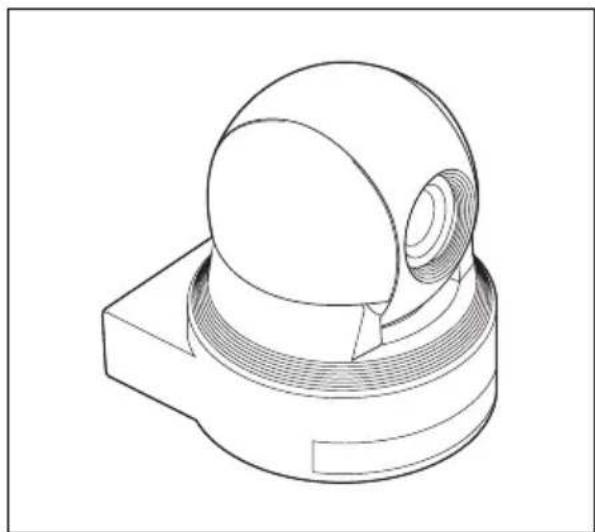
natural_image
Technical line drawing of a mechanical component with a spherical top and flanged base (no text or symbols)AC power adaptor (MPA-AC1) (1)
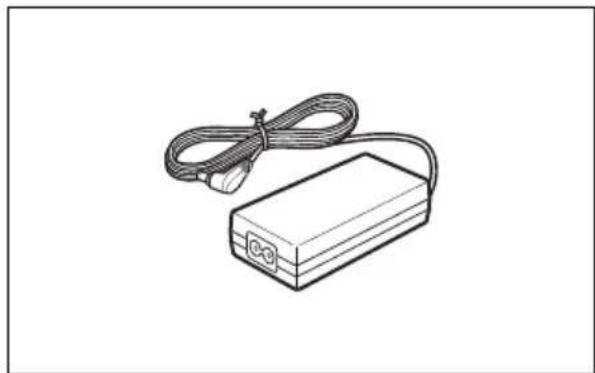
natural_image
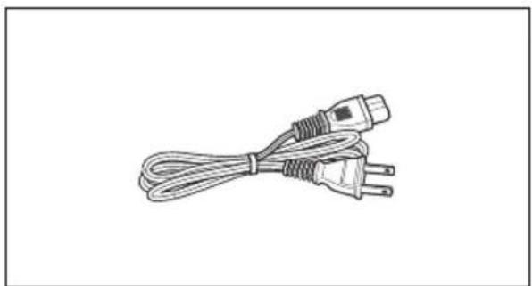
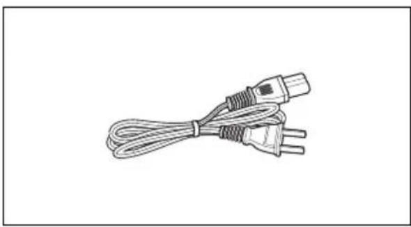
Line drawing of a rectangular electronic device with a coiled cable and connector (no text or symbols)AC power cord (1)
USA and Canadian model
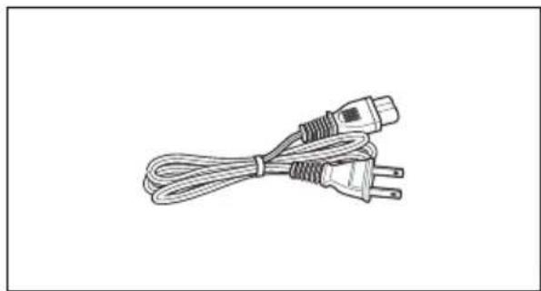
natural_image
Line drawing of a cable with three connectors (no text or symbols)European model
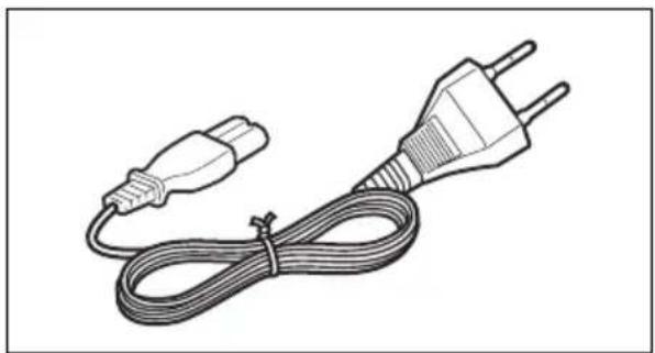
natural_image
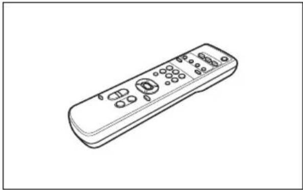
Line drawing of a two-pin electrical plug with coiled cable (no text or symbols)Remote commander (RM-EV100) (1)
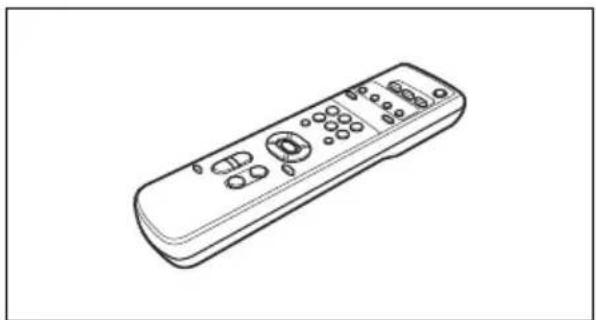
natural_image
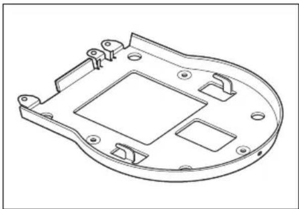
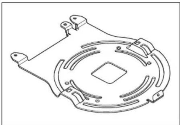
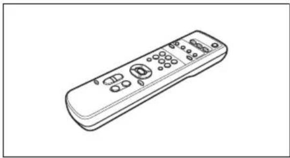
Line drawing of a remote control device with buttons and dials (no text or symbols)Ceiling bracket (A) (1)
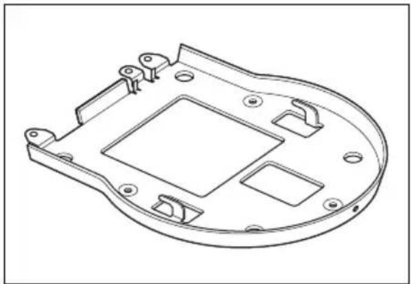
natural_image
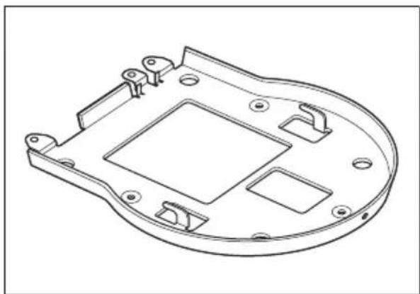
Technical line drawing of a mechanical component with mounting holes and internal cavity (no text or symbols)Ceiling bracket (B) (1)
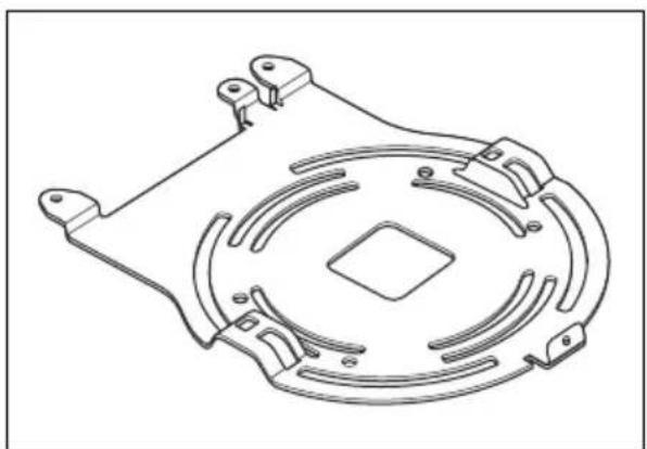
natural_image
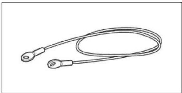
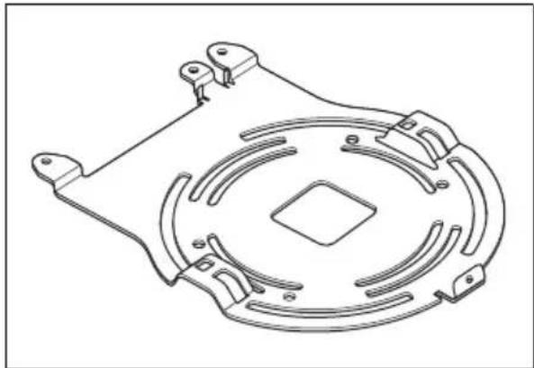
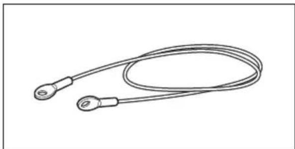
Technical line drawing of a mechanical component with circular and rectangular features (no text or symbols)Wire rope (1)
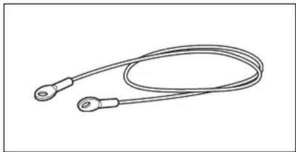
natural_image
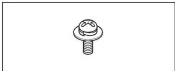
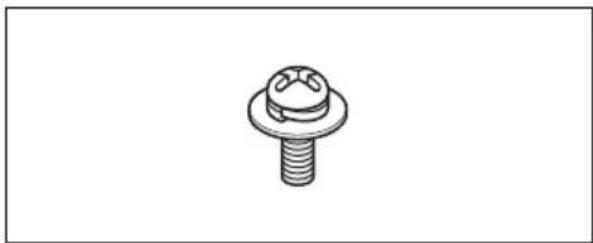
Line drawing of a coiled cable or wire with two terminal connectors (no text or symbols)Screw +M 3×8 (8)
natural_image
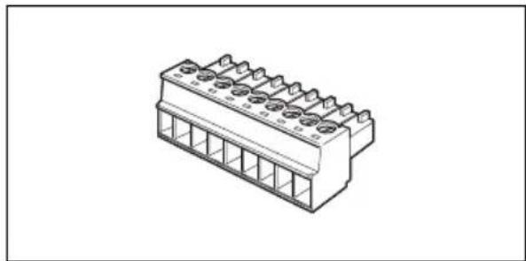
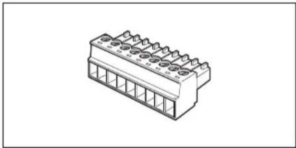
Technical line drawing of a bolt and nut assembly (no text or symbols)VISCA RS-422 connector plug (1)
natural_image
Isometric line drawing of a 3-pin electrical connector (no text or symbols)Operating Instructions (1)
Location and Functions of Parts and Controls
Camera
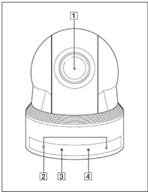
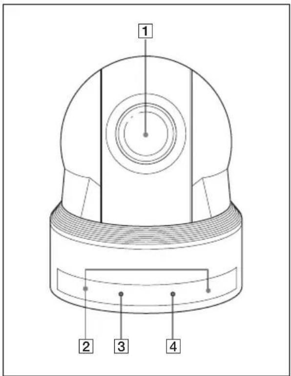
Front
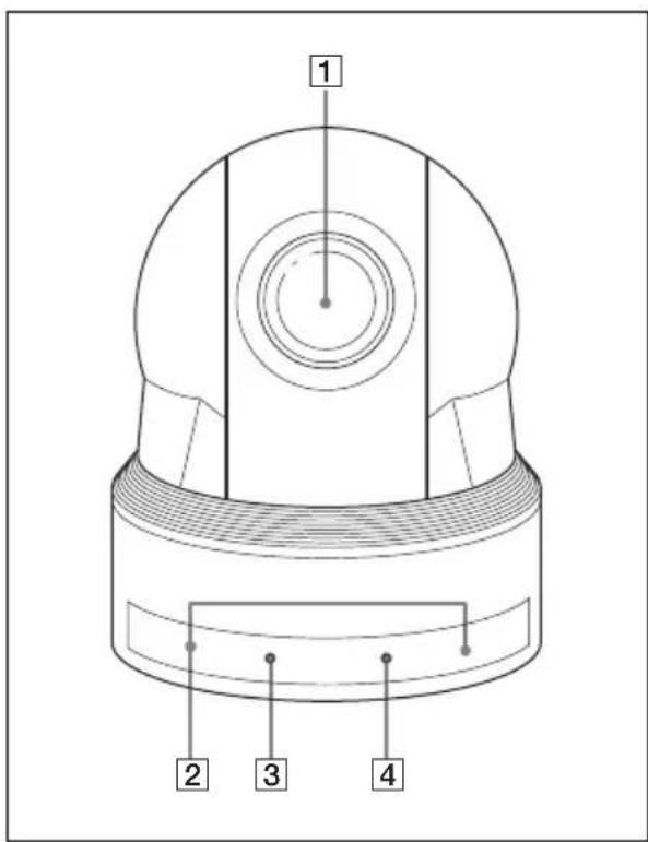
1 Lens
EVI-D80N/D80P : 18× magnification optical zoom lens
EVI-D90N/D90P : 28× magnification optical zoom lens
2 Remote sensors
These are sensors for the supplied remote commander.
3 POWER lamp
Lights when the camera is connected to an AC outlet using the supplied AC power adaptor and AC power cord.
Flashes in green when the camera receives an operation command from the supplied remote commander.
It takes about 7 to 16 seconds to display the image after the lamp lights.
4 STANDBY lamp
Lights when the camera is turned off using the remote commander.
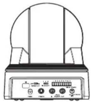
Rear
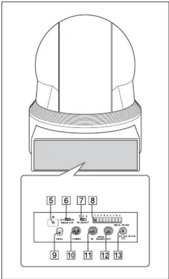
5 Remote sensors
These are sensors for the supplied remote commander.
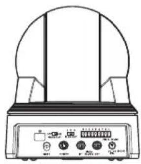
6 IMAGE FLIP switch
Flips the image upside down. Normally set this to OFF when you use the camera. When the camera is attached to the ceiling, set this to ON. Before you set the IMAGE FLIP switch, turn off the unit (or set to standby mode) and then, turn the power on by connecting the power adaptor, by VISCA control or the remote commander. When you switch this, the preset setting is returned to the initial setting. It takes about 7 to 16 seconds for the image displayed to respond to the setting change.
7 IR SELECT switch
Select the camera number when you operate multiple cameras with the same remote commander.
8 VISCA RS-422 connector
To communicate via RS-422, use this connector.
Use the supplied VISCA RS-422 connector plug.
9VIDEO(output) connector
10 S VIDEO(output) connector
11 VISCA IN connector
Connect to a computer via an RS-232C interface. When you connect multiple cameras, connect it to the VISCA OUT connector of the previous camera in the daisy chain connection.
12 VISCA OUT connector
When you connect multiple cameras, connect it to the VISCA IN connector of the next camera in the daisy chain connection.
13DC 12 V connector
Connect the supplied AC power adaptor.
Bottom
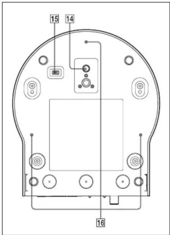
14 Tripod screw hole
15 BOTTOM switches
Used for RS-232C and RS-422 switching, 9,600 bps and 38,400 bps baud rate selection, D70 mode switching and IR signal output setting. For detailed information, refer to the Technical Manual of the camera.
16 Ceiling bracket mounting screw holes
Setting of the BOTTOM switches
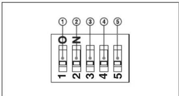
①D70 mode switch
Set to ON to use the VISCA command for EVI-D70/D70P.
②IR OUT switch
Set to ON to enable output of the receiver signals, which are transmitted from the infrared remote commander via the VISCA IN connector (page 95), or set it to OFF to disable the output.
③RS-232C/RS-422 select switch
Set to ON to operate colour video camera using the VISCA command via the RS-422 interface. To change the mode, turn off the camera (not including standby mode) first, set the switch and then turn on the camera again. Mode switching is not possible while the camera is turned on.
④Baud rate select switch
Set to ON for 38,400 bps or OFF for 9,600 bps. To change the mode, turn off the camera (not including standby mode) first, set the switch and then turn on the camera again. The mode cannot be switched while the camera is turned on.
⑤Switch 5 (Not used)
Be sure to set this switch to OFF.
Remote Commander (supplied)
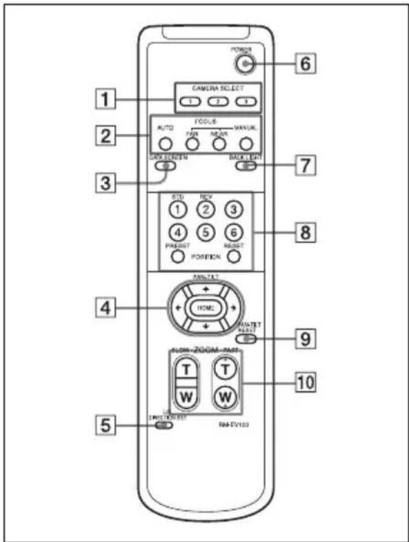
1 CAMERA SELECT buttons
Press the button corresponding to the camera you want to operate with the remote commander. The camera number can be set using the IR SELECT switch on the rear of the camera.
Note
If two or more cameras are adjacent and have the same camera number, they are operated simultaneously with the same remote commander. When you install the cameras close to each other, set different camera numbers.
For the camera number setting, see "Operating Multiple Cameras with the Remote Commander" (page 75).
2FOCUS buttons
Used for focus adjustment. Press the AUTO button to adjust the focus automatically. To adjust the focus manually, press the MANUAL button, and adjust it with the FAR and NEAR buttons.
Note
Press the MANUAL button and adjust the focus manually when shooting the following objects.
- White walls and other objects without contrast
- Objects behind glass
- Objects with horizontal stripes
- Objects on which bright lights are cast or reflected
• Nightscapes and other dark objects with blinking lights - Lit objects shot with darkened exposure adjustment or exposure compensation settings
3 DATA SCREEN button
Press this button to display the main menu. Press it again to turn off the menu. If you press the button when a lower-level menu is selected, the display goes back to a higher-level menu.
Note
Pan/tilt operations are disabled when the menu is displayed.
4 PAN-TILT buttons
Press the arrow buttons to perform panning and tilting. Press the HOME button to face the camera back to the front. When the menu is displayed, use ↑ or ↓ to select the menu items and ← or → to change the set values. The selected setting menu is displayed, by pressing the HOME button when the main menu is displayed.
5 L/R DIRECTION SET button
Hold down this button and press the REV button to change the direction of the camera movement opposite to that indicated by the arrow of the ◀/▶ buttons. To reset the direction of the camera movement, press the STD button while holding down this button.
6 POWER switch
Press this button to turn on/off the camera when the camera is connected to an AC outlet.
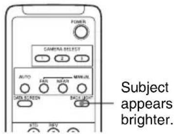
7 BACK LIGHT button
Press this button to enable the backlight compensation. Press it again to disable the backlight compensation.
8 POSITION buttons
Hold down the PRESET button and press button 1 to 6 to store the current camera direction, zooming, focus adjustment and backlight compensation in the memory of the pressed number button.
To erase the memory contents, hold down the RESET button and press button 1 to 6.
Note
These buttons do not function when the menu is displayed.
9 PAN-TILT RESET button
Press this button to reset the pan/tilt position.
10 ZOOM buttons
Use the SLOW button to zoom slowly, and the FAST button to zoom quickly. Press the T (telephoto) side of the button to zoom in, and the W (wide angle) side to zoom out.
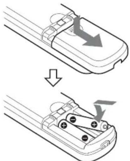
To install batteries
natural_image
Diagram showing a device being processed from top and side views, with arrows indicating motion direction (no text or symbols)Two R6 (size AA) batteries (not supplied)
Installing batteries
Two R6 (size AA) batteries are supplied for Remote Commander (RM-EV100).
To avoid risk of explosion, use R6 (size AA) manganese or alkaline batteries.
CAUTION
Danger of explosion if battery is incorrectly replaced.
Replace only with the same or equivalent type recommended by the manufacturer.
When you dispose of the battery, you must obey the law in the relative area or country.
ATTENTION
You can change various settings, such as shooting conditions and system setup of the camera, while observing menus displayed on a connected monitor.
This section explains how to read the on-screen menus before starting menu operations.
For the overall menu configurations, see "Menu Configuration" (page 87).
Notes
- You cannot perform pan/tilt operations while the menu is displayed.
- Depending on the connected monitor, characters displayed on the menu may flicker, or coloured diagonal stripes may appear. This behavior does not indicate a malfunction.
Main Menu
To display the main menu, press the DATA SCREEN button on the supplied remote commander.
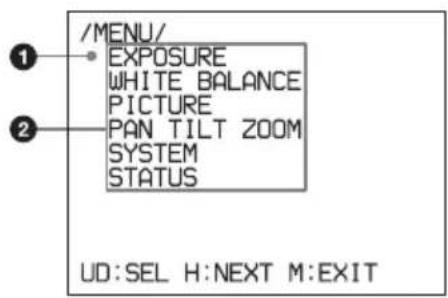
①Selected item
Selects a setting menu.
The selected item is displayed in red characters. The selected item moves up or down by pressing the ↑ or ↓ button on the remote commander.
②Menu items
To display a setting menu, select one using the ↑ or ↓ button on the remote
commander and press the HOME button on the remote commander.
Setting Menus
The setting menu selected on the main menu is displayed.
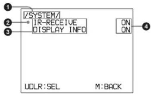
①Setting menu
The name of the setting menu currently selected is displayed here.
②Selected item
The selected item is displayed in red characters.
Selects a setting item.
Move the cursor up or down by pressing the ↑ or ↓ button on the remote commander.
③Setting items
The setting items for this setting menu are displayed.
Select the setting item using the ↑ or ↓ button on the remote commander.
④ Set value
The currently set values are displayed. To change a set value, use the ◆ or ➤ button on the remote commander.
For the default value of each setting item, see "Menu Configuration" (page 87).
Control Button Display Section
Names of buttons displayed on the monitor are different from buttons on the remote commander to be used.
Use the proper buttons on the remote commander, referring to the following pictures.
Main menu
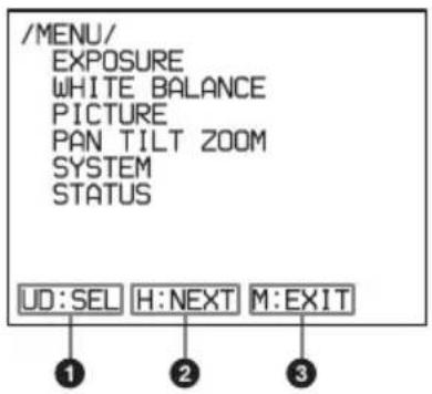
① Indicates that you can select a menu item by ↑ or ↓ button on the remote commander. The selected item is displayed in red characters.
②Indicates that you can move to the next layer by pressing the HOME button.
③ Indicates that you can return to the normal display by pressing the DATA SCREEN button.
Setting menu
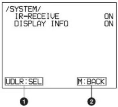
① Indicates that you can select the setting item by using the ↑ or ↓ button and you can change the set value by using the ← or → button.
② Indicates that you can return to the main menu by pressing the DATA SCREEN button.
Operating the Camera Using Menus
This section explains how to perform operations using the supplied remote commander.
For details on each menu, see page 67 to page 71.
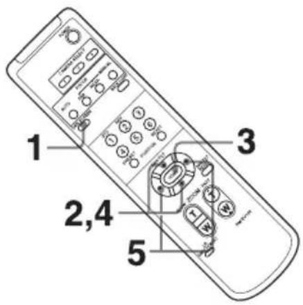
1 Press the DATA SCREEN button. The main menu appears.
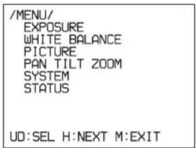
2 Select the menu item by pressing or . The selected item is displayed in red characters.
3 Press the HOME button.
The selected menu appears.
4 Select the menu item by pressing or . The selected item is displayed in red characters.
5 Change the value by pressing the ◀ or ➔ button.
Note
When you are operating the menu using the supplied remote commander, you cannot set IR-RECEIVE in the SYSTEM menu to OFF. To set IR-RECEIVE to OFF, use the appropriate VISCA command.
For detailed information on how to connect and VISCA command list, refer to the Technical Manual of the camera. For details on obtaining a Technical Manual, consult your Sony dealer.
To return to the main menu
Press the DATA SCREEN button.
To return to the normal display
Press the DATA SCREEN button when the main menu is displayed.
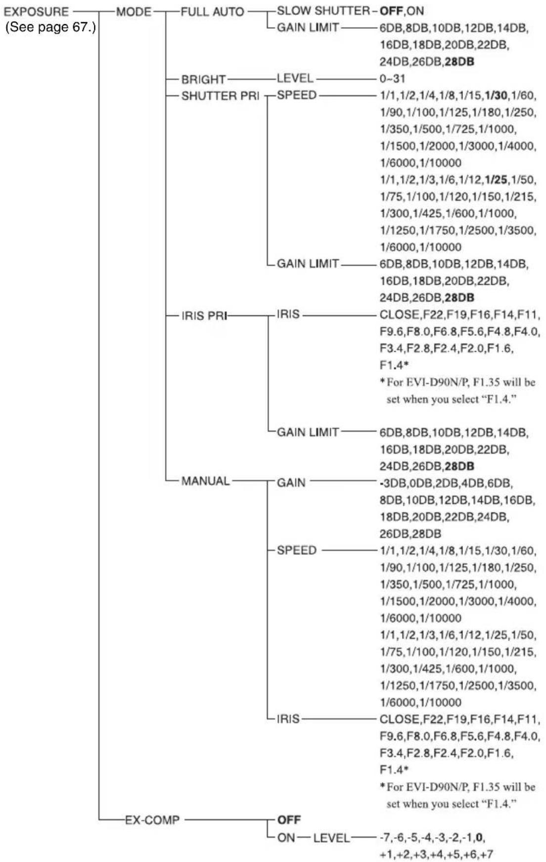
EXPOSURE Menu
The EXPOSURE menu is used to set the items related to the exposure.
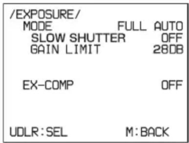
MODE (exposure mode)
FULL AUTO: The exposure is adjusted automatically using the sensitivity, electronic shutter speed, and iris.
BRIGHT: Adjust the brightness level (LEVEL) manually.
SHUTTER PRI: Shutter Priority mode. The exposure is adjusted automatically using the sensitivity and iris. Adjust the electronic shutter speed (SPEED) manually.
IRIS PRI: Iris Priority mode. The exposure is adjusted automatically using the sensitivity and electronic shutter speed. Adjust the iris (IRIS) manually.
MANUAL: Adjust the sensitivity (GAIN), electronic shutter speed (SPEED) and iris (IRIS) manually.
When you select one from among the various exposure modes, some of the following setting items that are required for the selected mode appear.
GAIN: Select the gain from among the following: -3, 0, 2, 4, 6, 8, 10, 12, 14, 16, 18, 20, 22, 24, 26, 28 dB
SPEED: Select the electronic shutter speed from among the following:
EVI-D80N/D90N:
1/1, 1/2, 1/4, 1/8, 1/15, 1/30, 1/60, 1/90, 1/100, 1/125, 1/180, 1/250, 1/350, 1/500, 1/725, 1/1000, 1/1500, 1/2000, 1/3000, 1/4000, 1/6000, 1/10000 sec.
EVI-D80P/D90P:
1/1, 1/2, 1/3, 1/6, 1/12, 1/25, 1/50, 1/75, 1/100, 1/120, 1/150, 1/215, 1/300, 1/425, 1/600, 1/1000, 1/1250, 1/1750, 1/2500, 1/3500, 1/6000, 1/10000 sec.
IRIS: Select the iris from among the following:
CLOSE, F22, F19, F16, F14, F11, F9.6, F8.0, F6.8, F5.6, F4.8, F4.0, F3.4, F2.8, F2.4, F2.0, F1.6, F1.4*
* For EVI-D90N/P, F1.35 will be set when you select "F1.4."
LEVEL: Select the brightness level from among 0 to 31.
GAIN LIMIT: Select the upper limit of the gain rise in FULL AUTO, SHUTTER PRI and IRIS PRI modes. Select from among 6, 8, 10, 12, 14, 16, 18, 20, 22, 24, 26 or 28 dB.
EX-COMP (exposure compensation)
When MODE is set to one of FULL AUTO, SHUTTER PRI or IRIS PRI, set this item to ON to enable exposure compensation.
When you set EX-COMP to ON, LEVEL appears and you can select the exposure compensation level from among the following:
$$ \begin{array}{l} - 7, - 6, - 5, - 4, - 3, - 2, - 1, 0, + 1, + 2, + 3, + 4, \ + 5, + 6, + 7 \end{array} $$
If you set the level to 0, exposure compensation will be disabled. Level +7 is the brightest and -7 is the darkest compensation value.
When EX-COMP is set to OFF, exposure compensation does not function.
SLOW SHUTTER
When you set the mode to ON, the camera automatically uses slow shutter speed for exposure as the illumination of the object to be shot decreases. This mode is only available when AE mode is set to FULL AUTO.
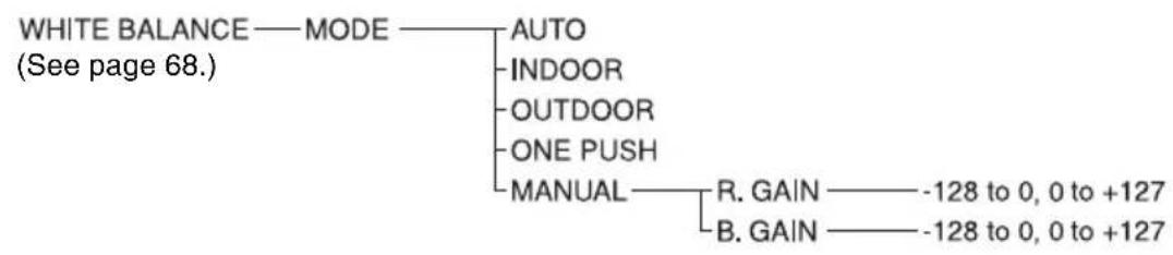
WHITE BALANCE Menu
The WHITE BALANCE menu is used to select the white balance mode.
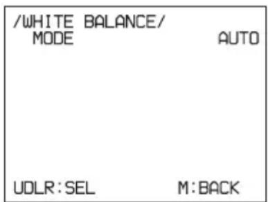
MODE (white balance mode)
Select the white balance mode from among the following:
AUTO, IN DOOR, OUT DOOR, ONE PUSH, MANUAL
When you select MANUAL, R.GAIN (red gain) and B. GAIN (blue gain) appear. You can select each item in the range from -128 to +127.
When you select the ONE PUSH mode
Perform the following operation.
1 Zoom in on a white subject in the center of the screen.
2 Press the HOME button of the supplied remote commander.
The one-push white balance adjustment is activated.
When DISPLAY INFO (page 71) is set to ON on the SYSTEM menu, the result of the white balance adjustment is displayed on the monitor.
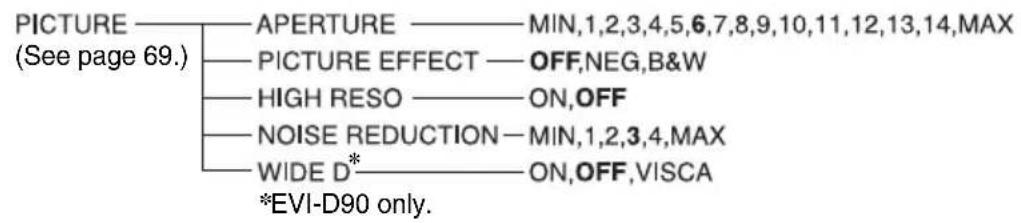
PICTURE Menu
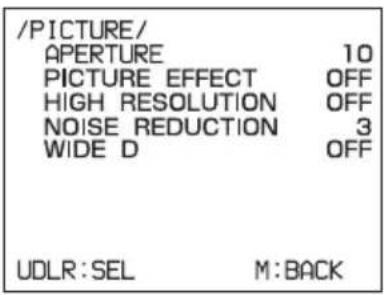
APERTURE (aperture compensation)
Select the aperture compensation level from among MIN, 1 to 14 and MAX.
PICTURE EFFECT
You can set this mode to OFF, NEG (negative-positive inverted) or B&W (black and white image).
HIGH RESOLUTION (High-resolution mode)
You can set this mode to ON or OFF. When set to ON, you can enjoy emphasised edge and high-resolution images.
NOISE REDUCTION
The NOISE REDUCTION function removes noise (both random and non-random) to provide clearer images. This function has 6 levels: levels 1 to 5, plus OFF.
WIDE D (Wide dynamic range mode) (EVI-D90N/D90P)
The camera adjusts the exposure depending on luminance levels. Even if the subjects are shot when facing the light or in places of high luminance, the camera produces images clearly differentiating between light and dark areas.
OFF: WIDE-D OFF
ON: WIDE-D ON
VISCA: Select mode except for ON/OFF by VISCA control. In this mode, control from the menu is not possible. For detailed information, refer to the Technical Manual of the camera. For details on obtaining a Technical Manual, consult your Sony dealer.
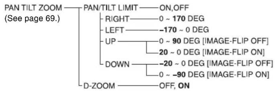
PAN TILT ZOOM Menu
The PAN TILT ZOOM menu is used to select the pan/tilt/zoom mode.
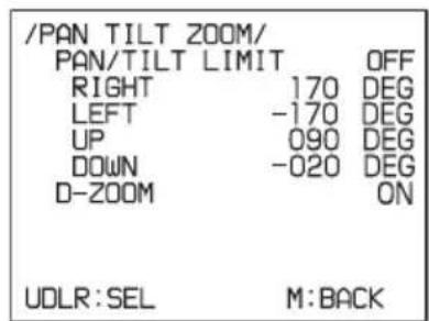
PAN/TILT LIMIT
When you set PAN/TILT LIMIT to ON, you can select the limit of pan/tilt operation. You can select the following values:
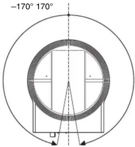
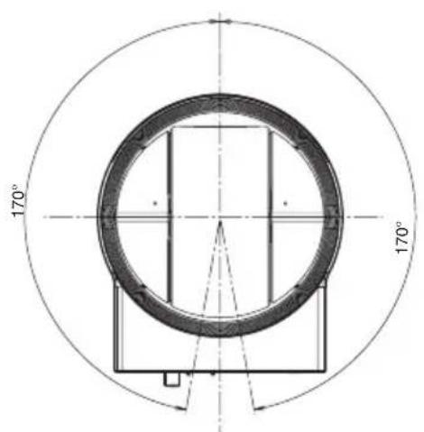
RIGHT: +170° to 0°, selectable with an interval of 1°
LEFT: 0^ to -170^ , selectable with an interval of 1^
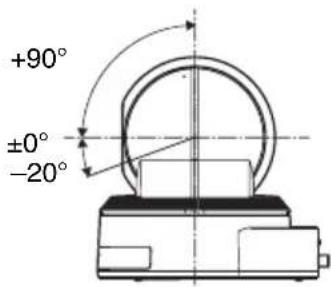
UP: +90° to 0° (IMAGE FLIP:OFF) +20° to 0° (IMAGE FLIP:ON) selectable in 1° steps.
DOWN: 0^ to -20^ (IMAGE FLIP:OFF) 0^ to -90^ (IMAGE FLIP:ON) selectable in 1^ steps.
Note
The indicated value is changed when the or ➤ button is released. When the pan/tilt function is in motion, the indicated value does not change.
Setting the range of LEFT/RIGHT movement
(IMAGE FLIP : OFF) CENTER (±0°)
Note
The limit of pan/tilt operation becomes effective promptly after you set the range of PAN/TILT LIMIT. When you want to make the camera start with the ranges set, before turning off the power, store those values in POSITION 1.
For details, see "Storing the Camera Settings in Memory — the Presetting Feature" (page 76).
Setting the range of UP/DOWN movement
(IMAGE FLIP : OFF)
Note
When you turn the camera to the right or left beyond the 120^ with the camera pointed downward by 20^ , the camera may be caught on the lens, depending on the zoom position of the lens.
D-ZOOM (digital zoom)
You can set digital zoom to ON or OFF. When set to OFF, digital zoom does not operate, and only optical zoom is available. When set to ON, digital zoom takes over after optical zoom reaches MAX (×20). Up to ×240 can be zoomed digitally.
SYSTEM Menu
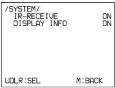
IR-RECEIVE (infrared signal reception)
When this is set to OFF, the camera does not receive the signal from the supplied remote commander.
Be sure to keep it set to ON when you use the supplied remote commander.
Note
You cannot set IR-RECEIVE to OFF when you operate the menu using the supplied remote commander. To set it to OFF, use the appropriate VISCA command.
DISPLAY INFO
When this item is set to ON, the message automatically appears for about 3 seconds on the monitor screen, when you perform the following operations using the supplied remote commander.
| Message When | |
| PRESET n : OK (“n” is a preset position number between 1 and 6) | You have stored the camera settings to POSITION 1 to 6. |
STATUS Menu
The STATUS menu is used to display the settings selected with the menus.
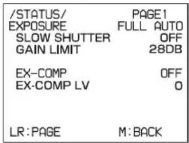
The STATUS menu consists of PAGE1 to PAGE4. This menu only displays the current menu settings, and you cannot change them with this menu.
PAGE1: Shows the settings selected with the EXPOSURE menu.
PAGE2: Shows the settings selected with the PICTURE menu and the WHITE BALANCE menu.
PAGE3: Shows the settings selected with the PAN TILT ZOOM menu.
PAGE4: Shows the settings selected with the SYSTEM menu, supplied remote commander channel, VISCA communication baud rate, D70 mode and the currently selected video output format.
Note
The current settings are displayed for the VISCA baud rate communication for the camera. Even if you change the settings after turning on the power, those settings are ignored and are not changed on the display.
Before Operating
Before operating the camera, check that the camera and peripheral devices are properly installed and connected.
For details, see "Installing the Camera" (page 78) and "Connections" (page 82).
Notes
- The supplied remote commander may not work correctly near the inverter lighting fixtures. In such a case, try to install the camera far from the inverted luminaire.
- You can check whether or not the installed location is good for the usage of the remote commander.
For detailed information on how to check, refer to the Technical Manual. For details on obtaining a Technical Manual, consult your Sony dealer.
Turning on the Power
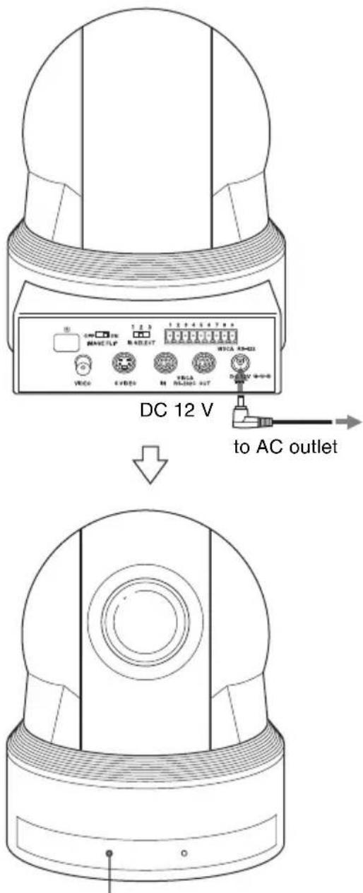
The POWER lamp lights.
1 Connect the camera to an AC outlet using the supplied AC power adaptor and power cord.
The power is turned on and the POWER lamp lights.
The camera will automatically pan and tilt and be reset to the position stored in POSITION 1 (Pan/tilt reset action).
2 Turn on the peripheral devices.
To turn on/off the camera using the remote commander
As long as the camera is connected to an AC outlet, you can turn the camera on or off with the POWER switch on the remote commander.
When you turn the power off using the remote commander, the POWER lamp turns off and the STANDBY lamp lights on the camera.
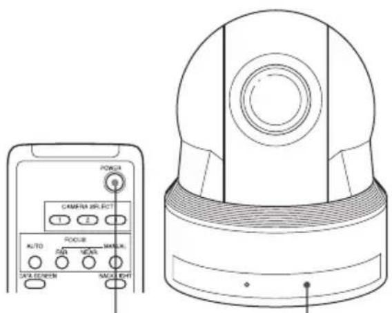
POWER The STANDBY lamp lights.
Pan/Tilt and Zoom Operation
Panning and Tilting
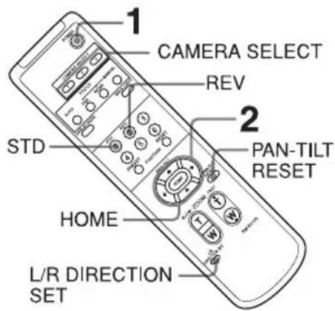
1 Press the POWER switch.
The camera will turn on and perform the pan/tilt reset operation automatically.
2 Press the arrow button to pan or tilt the camera.
While checking the picture on the screen, press the desired arrow button.
To move the camera little by little, press the button just for a moment.
To move the camera in a wide range, press and hold the button.
To move the camera diagonally, press the ◀ or ➤ button while holding down the ↑ or ↓ button.
To face the camera back to the front
Press the HOME button.
If the camera moves in a different direction from the one you intended
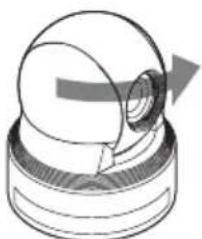
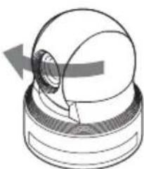
The camera is preset so that the image output from the camera is rotated toward the right whenever you press the ➤ button.
To face the camera toward the opposite direction:
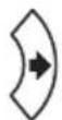
You might wish to face the camera toward the opposite direction from that of the button you pressed, for example, when you change the direction of the camera while checking the picture on the screen. In such a case, press the 2 (REV) button while holding down the L/R DIRECTION SET button.
| Arrow button | Movement of the camera | Setting |
 |  |  While holding down While holding down |
To reset the setting
To reset the setting, press the 1 (STD) button while holding down the L/R DIRECTION SET button.
| Arrow button | Movement of the camera | Setting |
 |  |  While holding down While holding down |
Note
The setting above only changes the signal emitted from the remote commander, and does not change the setting of the camera itself. Therefore, repeat the setting for each remote commander if you are using more than one remote commander.
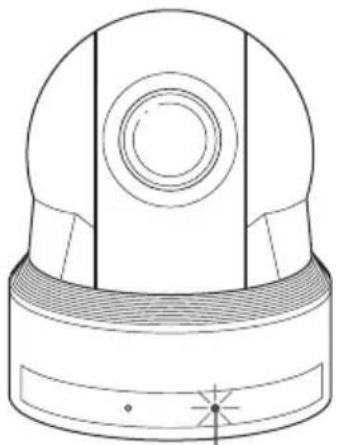
When the STANDBY lamp is blinking
natural_image
Technical line drawing of a mechanical component with a dome-shaped top and textured base (no text or symbols)The STANDBY lamp blinks.
If the camera is moved forcibly, or a finger or other object interferes with camera movement, the camera's built-in processor may fail to memorize the pan/tilt position. Press the PAN-TILT RESET button to reset the pan/tilt position.
Zooming
Press either of the ZOOM buttons.
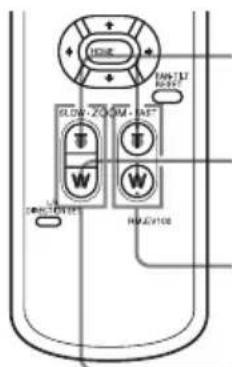
Subject appears closer. (Telephoto) Subject appears farther away. (Wide angle)
Zooms in or out fast (FAST side)
Zooms in or out slowly (SLOW side)
Note
When you perform pan/tilt operation while the camera is in the telephoto mode, the moving speed of the image on the screen may be a little jerky.
Operating Multiple Cameras with the Remote Commander
1 Set the IR SELECT switch on the rear of the camera you want to operate to 1, 2 or 3.
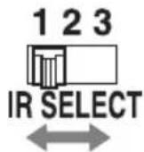
2 Press the CAMERA SELECT button on the remote commander that corresponds to the number set in step 1.
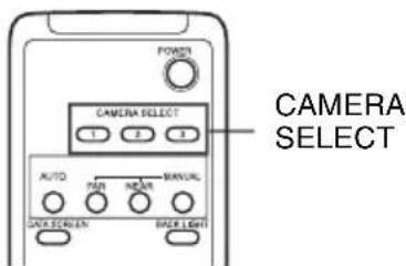
Then, you can operate the camera(s) specified by number. Every time you operate the camera(s) using the remote commander, the CAMERA SELECT button pressed in step 2 lights.
Adjusting the Camera
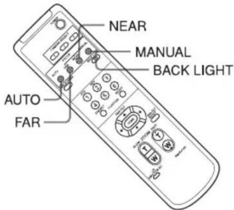
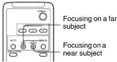
Focusing on a Subject
Focusing the camera on a subject automatically
Press the AUTO button. The camera focuses on the subject at the center of the screen automatically.
Focusing the camera on a subject manually
After pressing the MANUAL button, press either the FAR or the NEAR button to have the camera focus on the subject.
Shooting with Back Lighting
When you shoot a subject with a light source behind it, the subject becomes dark. In such a case, press the BACK LIGHT button.
To cancel the function, press the BACK LIGHT button again.
Note
The BACK LIGHT function is not effective if MODE is set to MANUAL in the EXPOSURE menu of the camera.
Storing the Camera Settings in Memory — the Presetting Feature
Up to six combinations of settings (six positions) including camera position, zooming, focusing, and backlighting, can be preset.
For details of the camera settings to be preset, see "Preset Items" (page 90).
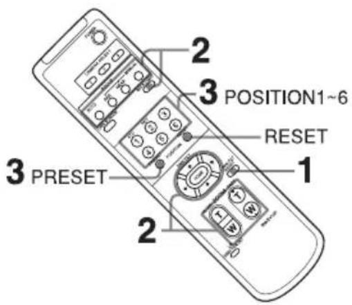
1 Press the PAN-TILT RESET button to reset the pan/tilt position.
2 Adjust the position, zooming, focusing and backlighting of the camera (page 73 to page 75).
3 While holding down the PRESET button, press any of the POSITION buttons, 1 to 6, in which you want to store the settings.
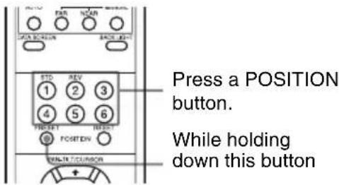
When you set DISPLAY INFO to ON on the SYSTEM menu, the message "PRESET n : OK" automatically appears for about 3 seconds on the monitor screen.
Recalling the stored settings
Press any of the POSITION buttons, 1 to 6, in which you have stored the settings.
Cancelling the preset memory
While holding down the RESET button, press the POSITION button from which you want to cancel the settings.
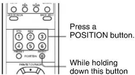
When you set DISPLAY INFO to ON on the SYSTEM menu, the message "RESET n : OK" automatically appears for about 3 seconds on the monitor screen.
Notes
- When the power is turned on, the camera starts with the settings stored in POSITION 1.
- If you want to retain the previous pan and tilt positions, etc. before the power is turned off and turned on again, store those positions in POSITION 1.
- When you are storing or cancelling the settings in one POSITION, you cannot call up, store or cancel the settings in another POSITION.
- When the menu is displayed on the screen, you cannot perform the operation for storing, recalling, or cancelling the setting. Be sure to return to the normal display before starting these operations.
Installing the Camera
Installing the Camera on a Desk
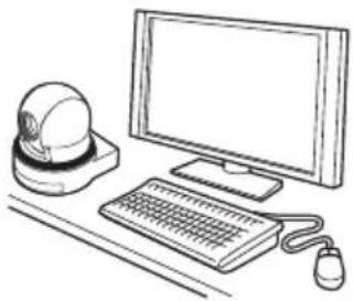
Place the camera on a flat surface. If you have to place the camera on an inclined surface, make sure that the inclination is less than ±15 degrees to guarantee pan/tilt performance, and take measures to prevent it from falling.
natural_image
Line drawing of a desktop computer setup with monitor, keyboard, mouse, and globe (no text or symbols)Notes
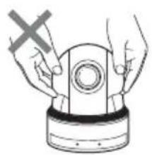
- Do not grasp the camera head when carrying the camera.
- Do not turn the camera head by hand. Doing so may result in a camera malfunction.
- If you turn the camera head by hand without AC power adaptor connected, the lamps on the front may light. This is not a malfunction.
natural_image
Illustration of hands holding a mechanical component with a cross mark, no text or symbols present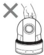
natural_image
Illustration of a hand holding a device with a cross mark, no text or symbols present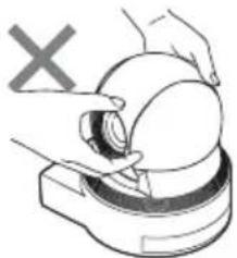
natural_image
Illustration of hands operating a device with a circular component, no text or symbols present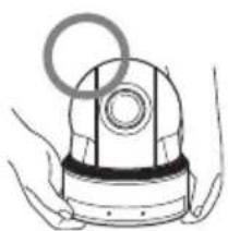
natural_image
Illustration of a mechanical device with a circular ring and hands (no text or symbols)Attaching the Camera to a Tripod
Attach a tripod to the screw hole used for attaching a tripod on the bottom of the camera.
The tripod must be set up on a flat surface and its screws tightened firmly by hand.
Use a tripod with screws of the following specifications.
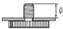
$$ \begin{array}{l} \ell = 4. 3 - 5 \mathrm{mm} \ \ell = 0. 1 7 - 0. 2 0 \text { inches } \ \end{array} $$
Caution
Installation of the camera using the tripod screws and screw holes should not be done for installation on a ceiling or a shelf, etc., in a high position.
Installing the unit on the ceiling
Using the ceiling bracket, wire rope, and screws supplied, you can utilize existing junction boxes, etc., to attach the camera to the ceiling.
When you install the unit, always install it on a level ceiling. If you have to install it on a sloping or uneven ceiling, make sure that the place where you install it is within ±15 degrees of the horizontal.
CAUTION
- Entrust installation to an experienced contractor or installer when installing the unit on ceilings or other high locations.
- When installing the unit in a high location, be sure that the location and installation components (excluding the supplied accessories) are strong enough to withstand at least 20 kg of weight, and install the unit securely. If the components are not strong enough, the unit may fall and cause serious injury.
• Always install the supplied wire rope to prevent the unit from falling.
- If you install the unit in a high location, check periodically, at least once a year, to ensure that the connection has not loosened. If conditions warrant, make this periodic check more frequently.
Before installation
After deciding the direction in which the camera will shoot, make the required holes for the junction box, and connecting cables.
Note
The connecting cables cannot be passed through ceiling bracket (A). A hole for the wiring is required in the ceiling at the back of the unit where it is attached to the ceiling.
Installation
1 Set the IMAGE FLIP switch on the rear panel to ON.
Notes
- Make sure that the BOTTOM switch is set to the correct position. See “Setting of the BOTTOM switches” (page 62).
- If you set the IMAGE FLIP switch to ON after turning on the power, the image will not be flipped. Turn the power off once, then on again, and the image will be flipped. It takes about 7 to 16 seconds to display the image.
- When you toggle the IMAGE FLIP switch, the pre-set settings will all be returned to the initial settings.
2 Attach the wire rope to the junction box in the ceiling.
Use a screw hole and a screw (not supplied) in the junction box to attach the wire rope.
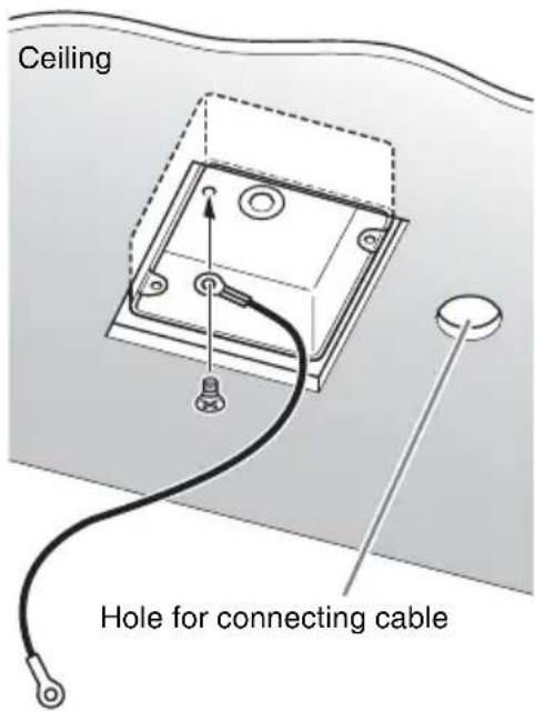
3 Attach the ceiling bracket (B) to the junction box on the ceiling.
Align the holes in the bracket with those in the junction box, and use appropriate screws (not supplied).
There are elongated holes for the screws along the rounded edges of the ceiling bracket (B). Later, the front of the camera will be positioned along this edge. Face the camera to the front, adjust the aim, and attach it securely.
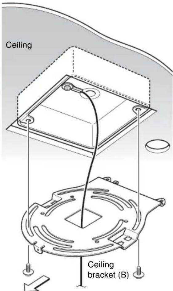
Front of the camera
4 Attach the ceiling bracket (A) to the bottom of the camera using the 3 screws (M 3 × 8) supplied.
Align the screw holes on the bottom of the camera with those in the ceiling bracket, and attach the bracket to the camera.
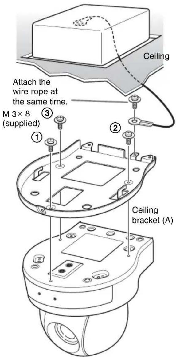
Tighten the screws a bit at a time in the numbered order shown in the illustration. Attach the wire rope using the screw designated as number ③ above. After all of the screws are inserted and temporarily tightened properly, securely tighten each one in turn.
Note
For assembly, use only the screws supplied with the unit. Using other screws may damage the unit.
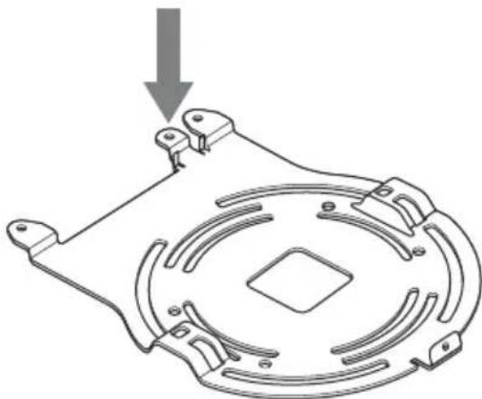
5 Insert the protrusions raised on the ceiling bracket (A) into the spaces prepared in the ceiling bracket (B), and temporarily attach them by pushing the ceiling bracket (A) to the rear.
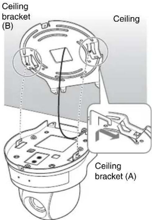
5-2 If the wire rope cannot be attached to the junction box, attach to the position on the ceiling bracket (B) in the illustration.
natural_image
Technical line drawing of a mechanical component with a circular base and mounting holes, showing a downward arrow indicating force or assembly (no text or symbols present)6 While pushing up on the front part of the camera, attach it using the three screws provided (M 3 × 8), starting with the screw at position ①.
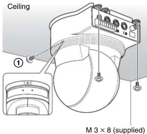
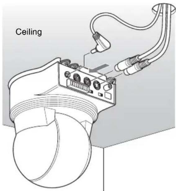
7 Connect the cables to the connectors on the rear of the camera.
Note
Take the proper steps to ensure that the load of the cables connected does not cause problems.
Removing the camera
1 Remove the three screws used to attach the camera in step 6 of "Installation."
2 While pushing the entire camera up towards the ceiling, move the camera to the front.
The hooks will disengage, and you can remove the camera.
Installing the Camera Using the M3 Fixing Screw Holes
Attach the camera using 3 M3 fixing screw holes located on the bottom of the camera. Attach the camera to a fitting with a flat surface using M3 screws with the following specifications.
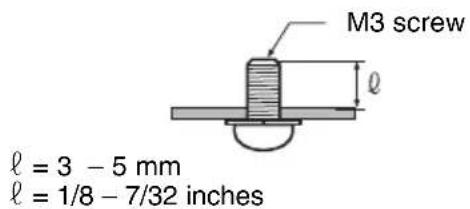
Connections
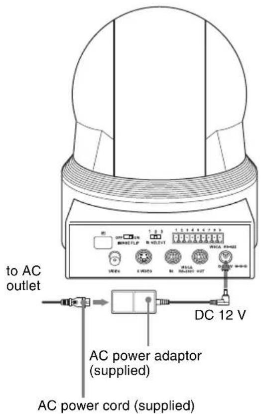
Connecting to an AC Outlet
Use the supplied AC power adaptor and AC power cord to connect the camera to an AC outlet.
Connecting a Computer
RS-232C Connections
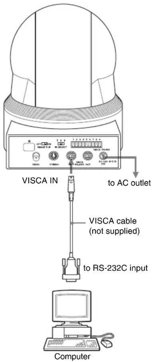
Notes
- When you connect a computer to the camera using the VISCA cable (RS-232C cross cable), you can control the camera from a computer instead of the supplied remote commander.
- In the case of VISCA RS-232C connection, make sure that the BOTTOM switch is set to RS-232C (page 62).
- It is not possible to connect both VISCA RS-232C and VISCA RS-422 simultaneously.
- Do not mix VISCA RS-232C (cross) and VISCA RS-422 cables. Using these cables
at the same time may result in malfunction.
To obtain a cable, consult your Sony dealer. For detailed information on how to connect the camera and the VISCA command list, refer to the Technical Manual of the camera. For details on obtaining a Technical Manual, consult your Sony dealer.
RS-422 Connections
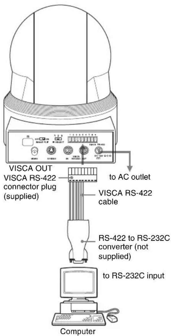
Notes
- Make up the cable using the supplied VISCA RS-422 connector plug. See "Using the VISCA RS-422 connector pin assignments" (page 95).
-
In the case of VISCA RS-232C connection, make sure that the BOTTOM switch is set to RS-232C (page 62).
-
It is not possible to connect both VISCA RS-232C and VISCA RS-422 simultaneously.
- Do not mix VISCA RS-232C (cross) and VISCA RS-422 cables. Using these cables at the same time may result in malfunction.
Connecting a video monitor or VTR equipped with a composite or S video input connector
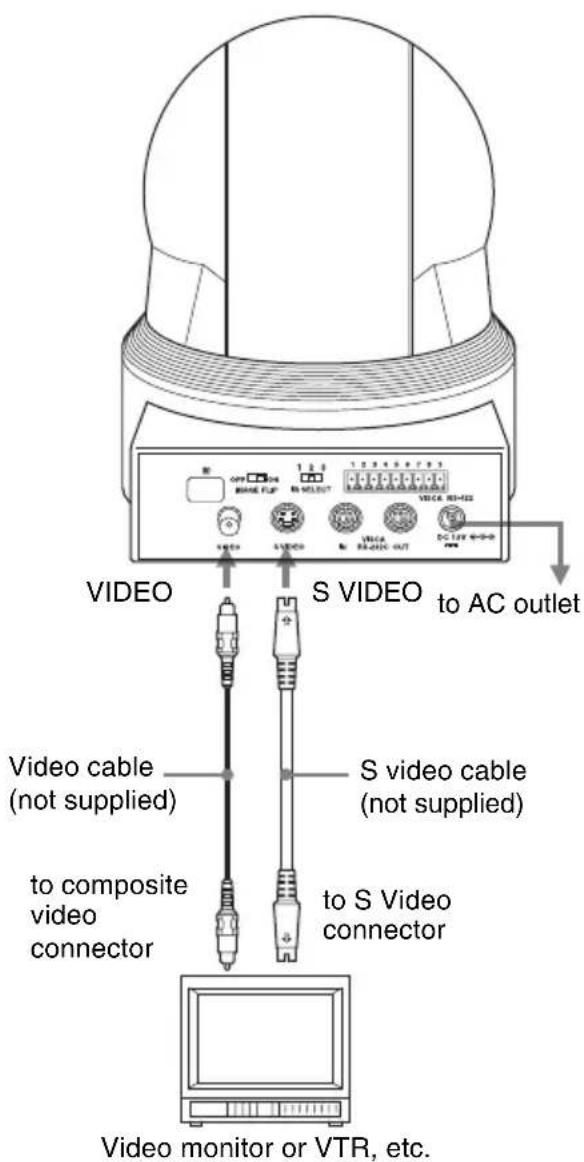
Note
It takes about 7 to 16 seconds to display the image.
Message List
The following messages and indications may appear for this camera. Perform the following as necessary.
Lamp display
| Lamp Meaning and solution | |
| The STANDBY lamp and POWER lamp are lit. | Set BOTTOM switch (5) to ON. |
| The STANDBY lamp is lit. | If the camera is moved forcibly, or a finger or other object interferes with camera movement, the camera’s built-in processor may fail to memorize the pan/tilt position.Press the PAN-TILT RESET button to reset the pan/tilt position. |
Screen display
| Message Meaning and solution | |
| PRESET n:OK(“n” is a preset position number between 1 and 6) | This message appears for about 3 seconds when you store camera settings to POSITION 1 to 6. |
| RESET n:OK(“n” is a reset position number between 1 and 6) | This message appears for about 3 seconds when you reset camera settings stored in POSITION 1 to 6. |
| ONE PUSH WB:OP During the white balance adjustment in the ONE PUSH white balance mode, this message blinks on the screen. | |
| ONE PUSH WB:OK When the white balance adjustment has been done correctly in the ONE PUSH white balance mode, this message is lit on the screen. | |
| ONE PUSH WB:NG When the white balance adjustment has failed in the ONE PUSH white balance mode, this message blinks on the screen. | |
Troubleshooting
Before bringing in your camera for service, check the following as a guide to troubleshooting the problem. If the problem cannot be corrected, consult your Sony dealer.
| Symptom Cause Remedy | ||
| The power of the camera is not turned on. | The AC power adaptor is not connected to the DC 12 V connector firmly. | Insert the power cord firmly as far as it will go. |
| The AC power cord is not inserted firmly into the AC power adaptor or the AC outlet. | Insert the power cord firmly as far as it will go. | |
| The picture is not displayed on the video monitor connected to the camera. | The video cable is not connected properly. | Check the connection between the camera and video monitor. |
| The exposure is not set correctly on the camera. | Set the exposure correctly on the EXPOSURE menu (page 67). | |
| Pan, tilt, or zoom cannot be operated. | A menu is displayed on the monitor screen. | Press the DATA SCREEN button on the supplied remote commander to remove the menu from the monitor screen. |
| The panning or tilting range is limited. | Change the PAN/TILT LIMIT setting on the PAN TILT ZOOM menu (page 69). | |
| The remote commander does not work. | The CAMERA SELECT button you pressed on the remote commander does not match the number set with the IR SELECT switch on the camera. | Press the CAMERA SELECT button corresponding to the IR SELECT switch setting on the camera (page 75). |
| The VISCA control is not available with a computer connected to the camera. | The computer is not correctly connected to the camera. | Make sure the connection between the computer and camera is made correctly. |
| Check that the baud rate setting (9,600 bps or 38,400 bps) is properly made with the BOTTOM switch on the bottom of the camera (page 62). | ||
| The camera cannot be operated at all. | - Pull out the plug of the power | cord from the AC outlet, then reinsert it into the AC outlet after waiting a while. |
Menu Configuration
The menus of the camera are configured as described below.
The initial settings of each item are in bold.
flowchart
graph TD
    A["EXPOSURE (See page 67.)"] --> B["FMODE"]
    B --> C["FULL AUTO"]
    C --> D["SLOW SHUTTER OFF,ON"]
    D --> E["GAIN LIMIT 6DB,8DB,10DB,12DB,14DB,16DB,18DB,20DB,22DB,24DB,26DB,28DB"]
    B --> F["BRIGHT LEVEL 0~31"]
    B --> G["SHUTTER PRI SPEED 1/1,1/2,1/4,1/8,1/15,1/30,1/60,1/90,1/100,1/125,1/180,1/250,1/350,1/500,1/725,1/1000,1/1500,1/2000,1/3000,1/4000,1/6000,1/10000"]
    B --> H["GAIN LIMIT 1/1,1/2,1/3,1/6,1/12,1/25,1/50,1/75,1/100,1/120,1/150,1/215,1/300,1/425,1/600,1/1000,1/1250,1/1750,1/2500,1/3500,1/6000,1/10000"]
    B --> I["GAIN LIMIT 6DB,8DB,10DB,12DB,14DB,16DB,18DB,20DB,22DB,24DB,26DB,28DB"]
    A --> J["IRIS PRI"]
    J --> K["IRIS CLOSE,F22,F19,F16,F14,F11,F9.6,F8.0,F6.8,F5.6,F4.8,F4.0,F3.4,F2.8,F2.4,F2.0,F1.6,F1.4* *For EVI-D90N/P, F1.35 will be set when you select "F1.4.""]
    A --> L["GAIN LIMIT 6DB,8DB,10DB,12DB,14DB,16DB,18DB,20DB,22DB,24DB,26DB,28DB"]
    A --> M["MANUAL"]
    M --> N["GAIN -3DB,0DB,2DB,4DB,6DB,8DB,10DB,12DB,14DB,16DB,18DB,20DB,22DB,24DB,26DB,28DB"]
    M --> O["SPEED 1/1,1/2,1/4,1/8,1/15,1/30,1/60,1/90,1/100,1/125,1/180,1/250,1/350,1/500,1/725,1/1000,1/1500,1/2000.1/3000.1/4000.1/6000.1/10000"]
    M --> P["IRIS CLOSE,F22,F19,F16,F14,F11,F9.6,F8.0,F6.8,F5.6,F4.8,F4.0,F3.4,F2.8,F2.4,F2.0,F1.6,F1.4* *For EVI-D90N/P, F1.35 will be set when you select "F1.4.""]
    A --> Q["EX-COMP OFF ON-LEVEL -7,-6,-5,-4,-3,-2,-1.0,+1,+2,+3,+4,+5,+6,+7"]
flowchart
graph TD
    A["WHITE BALANCE—MODE\n(See page 68.)"] --> B["AUTO"]
    B --> C["INDOOR"]
    B --> D["OUTDOOR"]
    B --> E["ONE PUSH"]
    B --> F["MANUAL"]
    F --> G["R. GAIN —-128 to 0, 0 to +127"]
    F --> H["B. GAIN —-128 to 0, 0 to +127"]
flowchart
graph TD
    A["PICTURE (See page 69.)"] --> B["APERTURE"]
    A --> C["PICTURE EFFECT"]
    A --> D["HIGH RESO"]
    A --> E["NOISE REDUCTION"]
    A --> F["WIDE D*"]
    B --> G["MIN,1,2,3,4,5,6,7,8,9,10,11,12,13,14,MAX"]
    C --> H["OFF,NEG,B&W"]
    D --> I["ON,OFF"]
    E --> J["MIN,1,2,3,4,MAX"]
    F --> K["ON,OFF,VISCA"]
    L["*EVI-D90 only."] --> M
flowchart
graph TD
    A["PAN TILT ZOOM"] --> B["Pan/TILT LIMIT"]
    B --> C["RIGHT"]
    B --> D["LEFT"]
    B --> E["UP"]
    B --> F["DOWN"]
    B --> G["D-ZOOM"]
    C --> H["0 ~ 170 DEG"]
    D --> I["-170 ~ 0 DEG"]
    E --> J["0 ~ 90 DEG [IMAGE-FLIP OFF"]]
    E --> K["20 ~ 0 DEG [IMAGE-FLIP ON"]]
    F --> L["-20 ~ 0 DEG [IMAGE-FLIP OFF"]]
    F --> M["0 ~ -90 DEG [IMAGE-FLIP ON"]]
    G --> N["OFF, ON"]

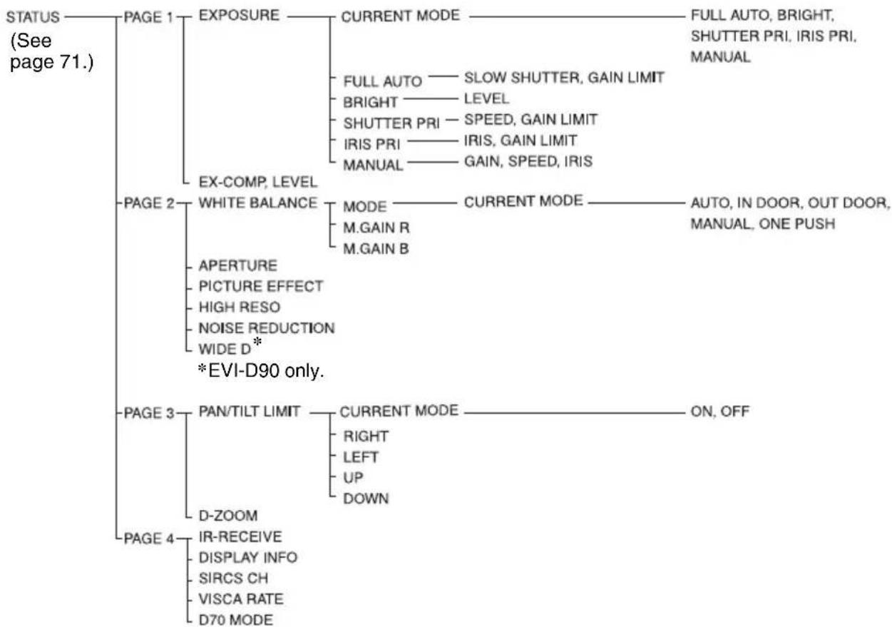
flowchart
graph TD
    A["STATUS (See page 71.)"] --> B["PAGE 1"]
    B --> C["EXPOSURE"]
    C --> D["CURRENT MODE"]
    D --> E["FULL AUTO, BRIGHT, SHUTTER PRI, IRIS PRI, MANUAL"]
    B --> F["EX-COMP, LEVEL"]
    F --> G["EXPOSURE"]
    G --> H["BRIGHT —— LEVEL"]
    G --> I["SHUTTER PRI —— SPEED, GAIN LIMIT"]
    G --> J["IRIS PRI —— IRIS, GAIN LIMIT"]
    G --> K["MANUAL —— GAIN, SPEED, IRIS"]
    B --> L["PAGE 2"]
    L --> M["WHITE BALANCE"]
    M --> N["MODE —— CURRENT MODE —— AUTO, IN DOOR, OUT DOOR, MANUAL, ONE PUSH"]
    M --> O["M.GAIN R"]
    M --> P["M.GAIN B"]
    L --> Q["APERTURE"]
    L --> R["PICTURE EFFECT"]
    L --> S["HIGH RESO"]
    L --> T["NOISE REDUCTION"]
    L --> U["WIDE D*"]
    L --> V["*EVI-D90 only."]
    B --> W["PAGE 3"]
    W --> X["PAN/TILT LIMIT"]
    X --> Y["CURRENT MODE —— ON, OFF"]
    X --> Z["D-ZOOM"]
    W --> AA["IR-RECEIVE"]
    AA --> AB["DISPLAY INFO"]
    AA --> AC["SIRCS CH"]
    AA --> AD["VISCA RATE"]
    AA --> AE["D70 MODE"]
Preset Items
The following items set by using the remote commander and menu items can be stored in the memory of the camera.
Items adjusted with the remote commander
*WIDE D is available on EVI-D90 only.
- :Setting items retained in memory when the power is turned off and then on again. The camera starts with these settings stored in POSITION 1.
○ :Setting items retained in memory when the power is turned off and then on again.
- :Setting items cleared from the memory when the power is turned off and then on and reset to the initial settings.
For detailed information on POSITION 1, see “Storing the Camera Settings in Memory — the Presetting Feature” (page 76).
You can store the following items in the memory (POSITION 1), but you can set them only by using the appropriate VISCA command.
- Focus Near Limit
- IR Receive
- IR Receive Return
For detailed information on the VISCA command list, refer to the Technical Manual of the camera. For details on obtaining a Technical Manual, consult your Sony dealer.
Specifications
System
Video signal EVI-D80N/ EVI-D90N: NTSC
EVI-D80P/EVI-D90P:PAL
Synchronization
Internal synchronization
Image device EVI-D80N/EVI-D80P: 1/4 type CCD
EVI-D90N/EVI-D90P: 1/4 type EXview HAD CCD
Lens EVI-D80N/EVI-D80P: 18×
(optical), 12× (digital)
f = 4.1 - 73.8 ~mm, F1.4 - F3.0
Horizontal angle: 2.8 (TELE end) to 48.0 degrees (WIDE end)
EVI-D90N/EVI-D90P: 28× (optical), 12× (digital)
f = 3.5 - 98.0mm, F1.35-F3.7
Horizontal angle: 2.1 (TELE end) to 55.8 degrees (WIDE end)
Minimum object distance
EVI-D80N/P: 10 mm (0.4 inches) (WIDE end) to 800 mm (31 1/2 inches) (TELE end) 290 mm (11 27/64 inches) (Default)
EVI-D90N/P: 10 mm (0.4 inches) (WIDE end) to 1500 mm (59 1/16 inches) (TELE end) 300 mm (11 13/16 inches) (Default)
Minimum illumination
EVI-D80N/EVI-D80P: less or equal to 0.4 lux (F1.4) with 50 IRE
EVI-D90N/EVI-D90P: less or equal to 0.65 lux (F1.35) with 50 IRE
Shutter speed 1 to 10,000 sec.
Video S/N More or equal to 50 dB
Pan/tilt action Horizontal: ±170 degrees Maximum panning speed: 100 degrees/sec.
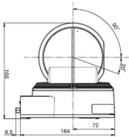
Vertical: +90, -20 degrees Maximum tilting speed: 90 degrees/sec.
Input/output connectors
Video output
COMPOSITE(VBS VIDEO
OUT): RCA phono jack (1), 75 ohm unbalanced, 1Vpp (at 75-ohm termination)
Synchronization: negative
S VIDEO output (Y/C VIDEO
OUT): Mini DIN 4-pin type
Control input/output
VISCA IN: Mini DIN 8-pin type, RS-232C
VISCA OUT: Mini DIN 8-pin type, RS-232C
VISCA RS-422: 9-pin
Power connector
JEITA type4 (DC 12 V)
General
Input voltage 12 V DC (10.8 to 13.2 V DC)
Current consumption
EVI-D80N/EVI-D80P: 0.5 A max. (at 12 V DC)
EVI-D90N/EVI-D90P: 0.67 A max. (at 12 V DC)
Operating temperature
0^ to 40^ (32°F to 104°F)
Storage temperature
-20^ to +60^ (-4^ to 140^)
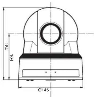
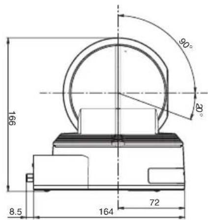
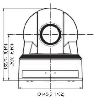
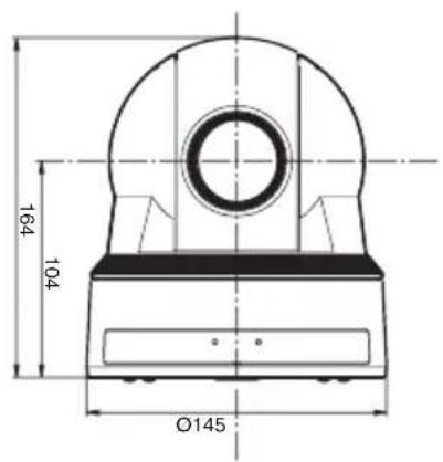
Dimensions Video camera: 145 × 164 ×
164 mm (5 1/32 × 6 15/32 ×
6 15/32 inches) (w/h/d, excluding protruding parts)
Remote Commander: 56 × 26 × 210 mm (2 1/4 × 1 1/16 × 8 3 inches) (w/h/d)
Mass Video camera:
EVI-D80N/EVI-D80P: 1440 g (3 lb 2 3/4 oz)
EVI-D90N/EVI-D90P: 1460 g (3 lb 3 1/2 oz)
Remote Commander: 110 g (37/8 oz)
Installation angle
Less than ±15 degrees to the horizontal surface
Supplied accessories
AC power adaptor (MPA-AC1)
(AC 100 V to 240 V, 50/60 Hz) (1)
AC power cord (1)
Remote Commander (RM-EV100) (1)
Ceiling bracket (A) (1)
Ceiling bracket (B) (1)
Wire rope (1)
Screw M 3 × 8 (8)
VISCA RS-422 connector plug (1)
Operating Instructions (1)
Design and specifications are subject to change without notice.
Note
Always verify that the unit is operating properly before use. SONY WILL NOT BE LIABLE FOR DAMAGES OF ANY KIND INCLUDING, BUT NOT LIMITED TO, COMPENSATION OR REIMBURSEMENT ON ACCOUNT OF THE LOSS OF PRESENT OR PROSPECTIVE PROFITS DUE TO FAILURE OF THIS UNIT, EITHER DURING THE WARRANTY PERIOD OR AFTER EXPIRATION OF THE WARRANTY, OR FOR ANY OTHER REASON WHATSOEVER.
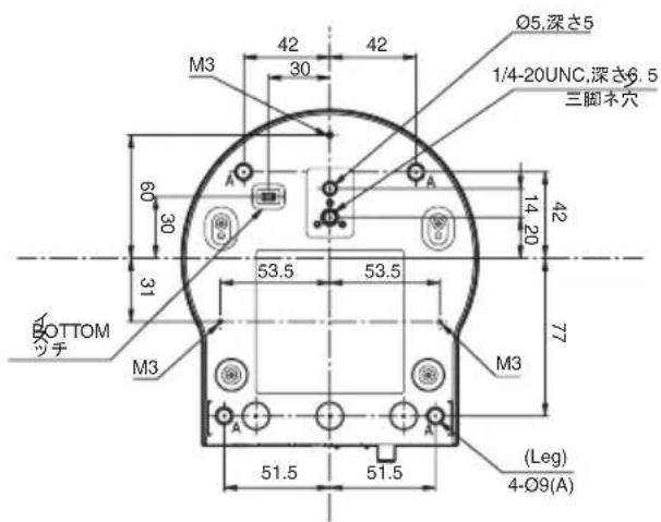
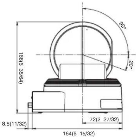
Dimensions
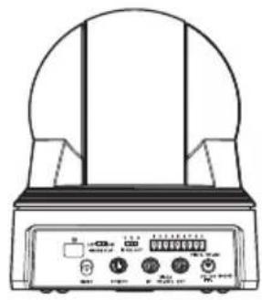
Top Back
natural_image
Line drawing of a portable electronic device with control buttons and a dome-shaped top (no text or symbols visible)Front
Side
Bottom
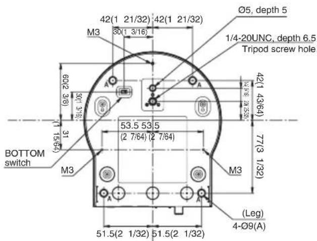
Unit: mm (inches)
Pin assignments
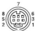
VISCA IN connector (mini-DIN 8-pin, female)
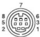
VISCA IN
| Pin No. Function | |||
| 1 | D | T | R |
| 2 | D | S | R |
| 3 | T | X | D |
| 4 GND | |||
| 5 | R | X | D |
| 6 GND | |||
| 7 IR OUT* | |||
| 8 | N | o | t |
* The IR OUT function of pins 7 is selectable with the BOTTOM switch on the bottom of the camera.
VISCA OUT connector (mini DIN 8-pin, female)
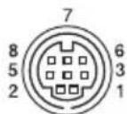
VISCA OUT
| Pin No. Function | |||
| 1 | D | T | R |
| 2 DSR OUT | |||
| 3 TXD OUT | |||
| 4 GND | |||
| 5 RXD OUT | |||
| 6 GND | |||
| 7 No connection | |||
| 8 No connection | |||
Using the VISCA RS-422 connector pin assignments
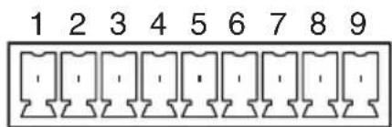
The VISCA RS-422 connector pin assignments
VISCA RS-422
| Pin No. Function | |
| 1 TXD IN+ | N |
| 2 TXD IN- | N |
| 3 RXD IN+ | N |
| 4 RXD IN- | |
| 5 I | GND |
| 6 TXD OUT+ | |
| 7 TXD OUT- | |
| 8tRXD OUT+s | c d |
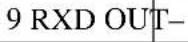 | |
O U T
Using the VISCA RS-422 connector plug
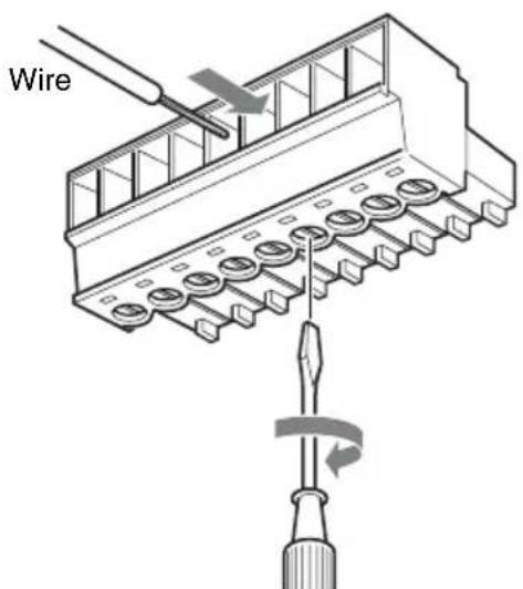
1 Insert a wire (AW G Nos. 28 to 18) into the desired wire opening on the supplied VISCA RS-422 connector plug, and tighten the screw for that wire using a flat-head screwdriver.
Flat-head screwdriver
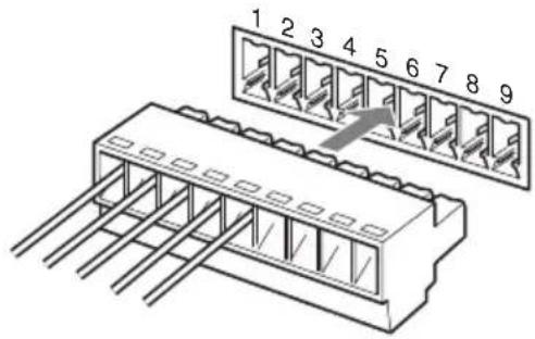
2 Insert the VISCA RS-422 connector plug into the VISCA RS-422 connector on the rear of the camera.
Notes
- In order to stabilize the voltage level of the signal, connect both ends to GND.
- Do not make a VISCA RS-232C connection when there is already an existing VISCA RS-422 connection.
警告
EXPOSURE 菜单 .....109
WHITE BALANCE 菜单 .....110
PICTURE 菜单 .....111
PAN TILT ZOOM 菜单 ..... 111
SYSTEM 菜单 112
STATUS 菜单 113
使用附送的遥控器操作
操作以前 114
打开电源 114
跟拍/倾斜和变焦操作 115
跟拍和倾斜 115
变焦 116
natural_image
Technical line drawing of a mechanical component with a spherical top and flanged base (no text or symbols)natural_image
Line drawing of a rectangular electronic device with coiled cable and connector (no text or symbols)交流电源线 (1)
natural_image
Line drawing of a cord with three leads, no text or symbols present遥控器 (RM-EV100) (1)
natural_image
Line drawing of a remote control with buttons and dials (no text or symbols)天花板托架 (A)(1)
natural_image
Technical line drawing of a mechanical component with mounting holes and internal cavity (no text or symbols)天花板托架 (B)(1)
natural_image
Technical line drawing of a mechanical component with circular and rectangular features (no text or symbols)钢丝绳 (1)
natural_image
Line drawing of a coiled cable or wire with two connectors (no text or symbols)螺丝 +M 3×8 (8)
natural_image
Technical line drawing of a bolt and nut assembly (no text or symbols)VISCA RS-422 连接器插头 (1)
natural_image
Isometric line drawing of a 3-pin electrical connector (no text or symbols)使用说明书 (1)
部件和控制器的位置和功能
摄像机
正面
1镜头
EVI-D80N/D80P: 18 倍光学变焦镜头
EVI-D90N/D90P: 28 倍光学变焦镜头
2 遥控感应器
这些感应器用于配合附送的遥控器使用。
3 POWER 指示灯
1 CAMERA SELECT 按钮
两节 R6 (AA) 电池 (未附送)
安装电池
附送两节 R6 (AA) 遥控器电池
(RM-EV100)。
(IMAGE FLIP : OFF)
CENTER (±0°)
注意
注意
natural_image
Technical line drawing of a mechanical component with a circular top and textured base (no text or symbols)STANDBY 指示灯闪烁。
natural_image
Line drawing of a desktop computer setup with monitor, keyboard, mouse, and globe (no text or symbols)注意
将摄像机安装到三脚架
natural_image
Technical line drawing of a mechanical component with mounting holes and a central square hole (no text or symbols)连接
连接到交流电源插座
- Focus Near Limit
- IR Receive
- IR Receive Return
于 0.65lx (F1.35, 50 IRE,
AGC MAX)
快门速度 1 到 10000 秒
视频信噪比 大于或等于 50 dB
跟拍 / 倾斜操作
水平:±170度
最大跟拍速度:100度/秒
垂直:+90、-20度
最大倾斜速度:90度 /秒
输入 / 输出连接器
natural_image
Line drawing of a portable electronic device with a dome-shaped top and control buttons (no text or symbols)正面
侧面
底部
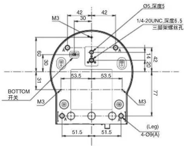
单位:mm
针脚指定
- 安全のために
- 各部の名称と働き
- 電池の使用について
- ご注意
- 三脚に取り付ける
- 入出力端子
- 端子のピン配列
- VISCA IN 端子
- WARNING
- IMPORTANT
- For the customers in the U.S.A.
- For the customers in Canada
- For the customers in Europe, Australia and New Zealand
- For the customers in Europe
- AVERTISSEMENT
- Overview
- Adjusting and Setting with Menus
- Operation Using the Supplied Remote Commander
- Installation and Connection
- Appendix
- Precautions
- Operating or storage location
- Ventilation
- Transportation
- Cleaning the main unit
- Replacing the batteries of the Remote Commander
- Maintenance
- Note on laser beams
- Phenomena Specific to CCD Image Sensors
- White flecks
- Aliasing
- Features
- Supplied Accessories
- Location and Functions of Parts and Controls
- Lens
- Remote sensors
- POWER lamp
- STANDBY lamp
- Remote sensors
- IMAGE FLIP switch
- Setting of the BOTTOM switches
- ①D70 mode switch
- ②IR OUT switch
- ③RS-232C/RS-422 select switch
- ④Baud rate select switch
- ⑤Switch 5 (Not used)
- Remote Commander (supplied)
- CAMERA SELECT buttons
- Note
- 2FOCUS buttons
- DATA SCREEN button
- PAN-TILT buttons
- L/R DIRECTION SET button
- POWER switch
- BACK LIGHT button
- POSITION buttons
- PAN-TILT RESET button
- ZOOM buttons
- Installing batteries
- CAUTION
- ATTENTION
- Notes
- Main Menu
- ①Selected item
- ②Menu items
- Setting Menus
- ①Setting menu
- ②Selected item
- ③Setting items
- ④ Set value
- Control Button Display Section
- Setting menu
- Operating the Camera Using Menus
- To return to the main menu
- To return to the normal display
- EXPOSURE Menu
- MODE (exposure mode)
- EVI-D80N/D90N:
- EVI-D80P/D90P:
- EX-COMP (exposure compensation)
- SLOW SHUTTER
- WHITE BALANCE Menu
- MODE (white balance mode)
- When you select the ONE PUSH mode
- PICTURE Menu
- APERTURE (aperture compensation)
- PICTURE EFFECT
- HIGH RESOLUTION (High-resolution mode)
- NOISE REDUCTION
- WIDE D (Wide dynamic range mode) (EVI-D90N/D90P)
- PAN TILT ZOOM Menu
- PAN/TILT LIMIT
- Setting the range of LEFT/RIGHT movement
- Setting the range of UP/DOWN movement
- D-ZOOM (digital zoom)
- SYSTEM Menu
- IR-RECEIVE (infrared signal reception)
- DISPLAY INFO
- STATUS Menu
- Before Operating
- Turning on the Power
- To turn on/off the camera using the remote commander
- Pan/Tilt and Zoom Operation
- Panning and Tilting
- To face the camera back to the front
- If the camera moves in a different direction from the one you intended
- To face the camera toward the opposite direction:
- To reset the setting
- When the STANDBY lamp is blinking
- Zooming
- Operating Multiple Cameras with the Remote Commander
- Adjusting the Camera
- Focusing on a Subject
- Focusing the camera on a subject automatically
- Focusing the camera on a subject manually
- Shooting with Back Lighting
- Storing the Camera Settings in Memory — the Presetting Feature
- Recalling the stored settings
- Cancelling the preset memory
- Installing the Camera
- Installing the Camera on a Desk
- Attaching the Camera to a Tripod
- Installing the unit on the ceiling
- Before installation
- Installation
- Removing the camera
- Installing the Camera Using the M3 Fixing Screw Holes
- Connections
- Connecting to an AC Outlet
- Connecting a Computer
- Connecting a video monitor or VTR equipped with a composite or S video input connector
- Message List
- Troubleshooting
- Menu Configuration
- Preset Items
- Specifications
- System
- Input/output connectors
- General
- Dimensions
- Pin assignments
- Using the VISCA RS-422 connector pin assignments
- Using the VISCA RS-422 connector plug
- 警告
- 使用附送的遥控器操作
- 部件和控制器的位置和功能
- 摄像机
- 1镜头
- 遥控感应器
- POWER 指示灯
- CAMERA SELECT 按钮
- 安装电池
- 注意
- 将摄像机安装到三脚架
- 连接
- 连接到交流电源插座
- 输入 / 输出连接器
- 针脚指定
Brand : SONY
Model : EVI-D90N
Category : Security Camera