
SRG-280SHE - Security Camera SONY - Free user manual and instructions
Find the device manual for free SRG-280SHE SONY in PDF.


| Product Type | PTZ Security Camera |
| Model | SRG-280SHE |
| Brand | Sony |
| Image Sensor | 1/2.8-type Exmor CMOS |
| Resolution | Full HD 1080p (1920x1080) |
| Optical Zoom | 20x |
| Digital Zoom | 12x |
| Horizontal Viewing Angle | 55.4° (wide end) |
| Minimum Illumination | 0.5 lux (typical) |
| Pan/Tilt Range | Pan: 340°, Tilt: +90° to -90° |
| Video Output | 3G-SDI, HDMI, IP (streaming) |
| Network Interface | 10/100BASE-TX Ethernet |
| Power Supply | DC 12V or PoE+ (IEEE 802.3at) |
| Power Consumption | 12W (typical) |
| Dimensions (W x H x D) | 153 x 160 x 153 mm |
| Weight | 2.1 kg |
| Operating Temperature | 0°C to 40°C (32°F to 104°F) |
| Mounting Type | Ceiling or wall mount (optional bracket) |
| Maintenance | Clean lens with soft, dry cloth; avoid liquid cleaners |
| Safety | Use certified power supply; ensure proper ventilation |
| Spare Parts & Repairability | Contact Sony authorized service center for genuine parts |
Frequently Asked Questions - SRG-280SHE SONY
User questions about SRG-280SHE SONY
0 question about this device. Answer the ones you know or ask your own.
Ask a new question about this device
Download the instructions for your Security Camera in PDF format for free! Find your manual SRG-280SHE - SONY and take your electronic device back in hand. On this page are published all the documents necessary for the use of your device. SRG-280SHE by SONY.
USER MANUAL SRG-280SHE SONY
HD Color Video Camera
Technical Manual
natural_image
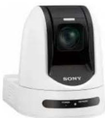
White Sony camera with black lens and control buttons (no visible text or symbols on device body)SRG-360SHE
SRG-280SHE
Table of Contents
Basic Functions .... 3
Overview of Functions ....3
Initial Settings and Preset 10
Mode Condition 11
Command List ....16
VISCA RS-422 Commands 16
IP Related Setting Command 26
SRG-360SHE/SRG-280SHE Commands 28
Basic Functions
Overview of Functions
Zoom
SRG-360SHE
Employs 30× optical zoom lens. Up to ×360 zoom is allowed when you use digital zoom.
•Optical ×30, f=4.3 mm to 129 mm
(F1.6 to F4.7)
SRG-280SHE
Employs 26× optical zoom lens. Up to ×312 zoom is allowed when you use digital zoom.
•Optical ×26, f=4.3 mm to 111.8 mm (F1.6 to F4.5)
Digital Zoom enlarges the center of the subject by expanding each image in both the vertical and horizontal directions. When the digital zoom is used, the resolution deteriorates.
You can activate the zoom in the following modes, all of which can be set using VISCA command.
Standard Mode
Variable Mode
There are eight levels of zoom speed.
In these standard and variable modes, it is necessary to send Stop Command to stop the zoom operation.
Direct Mode
Setting the zoom position enables quick movement to the designated position.
Digital Zoom ON/OFF
Focus
Focus has the following modes, all of which can be set using VISCA Commands.
- Auto Focus Mode
The Auto Focus (AF) function automatically adjusts the focus position to maximise the high frequency content of the picture in a center measurement area, taking into consideration the high luminance and strong contrast components. The minimum focus distance is 10 mm at the optical wide end and 1200 mm at the optical tele end.
- Normal AF Mode
This is the normal mode for AF operations.
- Interval AF Mode
The mode used for AF movements carried out at particular intervals. The time intervals for AF movements and for the timing of the stops can be set in one-second increments using the Set Time Command. The initial value for both is set to five seconds.
- Zoom Trigger Mode
When the zoom is changed, the AF mode activates for the pre-set time. Then, it stops. The initial value is set to 5 seconds.
AF sensitivity can be set to either Normal or Low.
- Normal
Reaches the highest focus speed quickly. Use this when shooting a subject that moves frequently.
Usually, this is the most appropriate mode.
- Low
Improves the stability of the focus. When the lighting level is low, the AF function does not take effect, even though the brightness varies, contributing to a stable image.
- Manual Focus Mode
Manual Focus has both a Standard Mode and a Variable Mode. Standard Mode focuses at a fixed rate of speed. Variable Mode has eight speed levels that can be set using a VISCA Command.
In these standard and variable modes, it is necessary to send Stop Command to stop the zoom operation.
- One Push Trigger Mode
When a Trigger Command is sent, the lens moves to adjust the focus for the subject. The focus lens then holds that position until the next Trigger Command is input.
- Infinity Mode
The lens is forcibly moved to a position suitable for an unlimited distance.
- Near Limit Mode
Can be set in a range from 1000 ( ∞ ) to F000 (1 cm). Default setting: D000h (30 cm)
White Balance
White Balance has the following modes.
• Auto White Balance
This mode computes the white balance value output using color information from the entire screen. It outputs the proper value using the color temperature radiating from a black subject based on a range of values from 2500K to 7500K. This mode is the factory setting.
• ATW
Auto Tracing White balance (2000K to 10000K)
- Indoor
3200K Base Mode
- Outdoor
5800K Base Mode
- One Push WB
One Push White Balance is a function that forcibly captures the white color once the lighting conditions to illuminate the subject are set, enabling you to shoot the image in the conditions as they are set. By using this function, the natural color of the subject can be obtained without being affected by the surrounding lighting conditions. To set this mode, shoot the subject that you want to capture the white color and send the One Push White Balance Trigger. The One Push White Balance data is lost when the power is turned off. If the power is turned off, set One Push White Balance again.
- Manual WB
Manual control of R and B gain, 256 steps each
Automatic Exposure Mode
A variety of AE functions are available for optimal output of subjects in lighting conditions that range from low to high.
• Full Auto
Iris, Gain and Shutter Speed can be set automatically.
- Gain Limit Setting
The gain limit can be set at the Full Auto, Shutter Priority, Iris Priority, Bright and Manual in the AE mode. Use this setting when image signal-to-noise ratio is particularly important.
- Shutter Priority 1)
Variable Shutter Speed, Auto Iris and Gain (1/1 to 1/10,000 sec., 16 high-speed shutter speeds plus 6 low-speed shutter speeds)
1) Flicker can be eliminated by setting shutter to
→ 1/100s for NTSC models used in countries with a 50 Hz power supply frequency
→ 1/120s for PAL models used in countries with a 60 Hz power supply frequency
- Iris Priority
Variable Iris (F1.6 to Close, 14 steps), Auto Gain and Shutter speed
- Manual
Variable Shutter, Iris and Gain
- Bright
Variable Iris and Gain (Close to F1.6, 14 steps and F1.6 at 15 steps)
AE – Shutter priority
The shutter speed can be set freely by the user to a total of 22 steps - 16 high speeds and 6 low speeds. When the slow shutter is set, the speed can be adjusted the slow shutter according to subject brightness. The picture output is read at a low rate from the memory. AF capability is low. In high speed mode, the shutter speed can be set up to 1/10,000s . The iris and gain are set automatically, according to the brightness of the subject.
| Parameter 59.94/29.97 mode | 50/25 mode | |
| 15 | 1/10000 | 1/10000 |
| 14 | 1/6000 | 1/6000 |
| 13 | 1/4000 | 1/3500 |
| 12 | 1/3000 | 1/2500 |
| 11 | 1/2000 | 1/1750 |
| 10 | 1/1500 | 1/1250 |
| 0F | 1/1000 1/1000 | |
| 0E | 1/725 | 1/600 |
| 0D | 1/500 | 1/425 |
| 0C | 1/350 | 1/300 |
| 0B | 1/250 | 1/215 |
| 0A | 1/180 | 1/150 |
| 09 | 1/125 | 1/120 |
| 08 | 1/100 | 1/100 |
| 07 | 1/90 | 1/75 |
| 06 | 1/60 | 1/50 |
| 05 | 1/30 | 1/25 |
| 04 | 1/15 | 1/12 |
| 03 | 1/8 | 1/6 |
| 02 | 1/4 | 1/3 |
| 01 | 1/2 | 1/2 |
| 00 | 1/1 | 1/1 |
AE – Iris priority
The iris can be set freely by the user to 14 steps between F1.6 and Close.
The gain and shutter speed are set automatically, according to the brightness of the subject.
| Parameter | Setting value | Parameter | Setting value |
| 11 | F1.6 | 0A | F5.6 |
| 10 | F2 | 09 | F6.8 |
| 0F | F2.4 | 08 | F8 |
| 0E | F2.8 | 07 | F9.6 |
| 0D | F3.4 | 06 | F11 |
| 0C | F4 | 05 | F14 |
| 0B | F4.8 | 00 | CLOSE |
AE - Manual
The shutter speed (22 steps), iris (14 steps) and gain (15 steps) can be set freely by the user.
AE - Bright
The bright control function adjusts both gain and iris using an internal algorithm, according to a brightness level freely set by the user. Exposure is controlled by gain when dark, and by iris when bright.
As both gain and iris are fixed, this mode is used when exposing at a fixed camera sensitivity. When switching from Full Auto or Shutter Priority Mode to Bright Mode, the current status will be retained for a short period of time.
Only when the AE mode is set to “Full Auto” or “Shutter Priority,” you can switch it to “Bright.”

| Parameter | Iris Gain | Parameter | Iris Gain | ||
| 1F F1.6 | +43 dB | 11 F1.6 | 0 dB | ||
| 1E F1.6 | +39 dB | 10 F2 | 0 dB | ||
| 1D F1.6 | +36 dB | 0F F2.4 | 0 dB | ||
| 1C F1.6 | +33 dB | 0E F2.8 | 0 dB | ||
| 1B F1.6 | +30 dB | 0D F3.4 | 0 dB | ||
| 1A F1.6 | +27 dB | 0C F4 | 0 dB | ||
| 19 F1.6 | +24 dB | 0B F4.8 | 0 dB | ||
| 18 F1.6 | +21 dB | 0A F5.6 | 0 dB | ||
| 17 F1.6 | +18 dB | 09 F6.8 | 0 dB | ||
| 16 F1.6 | +15 dB | 08 F8 | 0 dB | ||
| 15 F1.6 | +12 dB | 07 F9.6 | 0 dB | ||
| 14 F1.6 | +9 dB | 06 F11 | 0 dB | ||
| 13 F1.6 | +6 dB | 05 F14 | 0 dB | ||
| 12 F1.6 | +3 dB | 00 CLOSE | 0 dB |
When switching from the Shutter Priority mode to the Bright mode, the shutter speed set in the Shutter Priority mode is maintained.
Defog mode
When the surrounding area of the subject is foggy and low contrast, the defog mode will make the subject appear clearer.
Wide Dynamic Range Mode (WD)
The Wide Dynamic Range mode is a function for dividing an image into several blocks and correcting blocked-up shadows and blown-out highlights in accordance with the intensity difference. It enables you to obtain images in which portions ranging from dark to light can be recognized, even when capturing a subject with a large intensity difference that is backlit or includes extremely light portions.
Images with wide dynamic range are produced by combining long-exposure signals (normal shutter) with the signals of the high-intensity portions obtained with a short exposure (high-speed shutter).
- About WD Set Parameter
(Command: 8x 01 7E 04 00 0p FF)
p: WIDE D (Wide dynamic range mode)
When MODE (exposure mode) is set to FULL AUTO, the camera distinguishes light and dark areas in the same scene, adjusts the brightness for dark areas, and also controls the blown out highlights.
You can select the wide dynamic range mode from among OFF, LOW, MID and HIGH.
(0: OFF, 1: LOW, 2: MID, 3: HIGH.)
Notes
- You can set the wide dynamic range mode when the WIDE D is set to FULL AUTO only.
- When the WIDE D is not set to OFF, the MODE setting is fixed at FULL AUTO.
- When changing the WIDE D, the luminance change of the screen occurs for a moment.
- When the change of exposure is big, the screen may stop for a moment.
- When the wide dynamic range mode is ON, false colors may appear in some parts of the image. This phenomenon is unique to wide dynamic range mode, and is not an indication of a camera malfunction.
- When switching wide dynamic range mode, images are shown at a maximum of 8 frames at the same time.
- When the intensity difference of the image is small, there is no difference in effect between MID and HIGH.
Exposure Compensation
Exposure compensation is a function which offsets the internal reference brightness level used in the AE mode, by steps of 1.5 dB.
The reference brightness is 0.
| Parameter Step | Setting value |
| 0E +7 +1 0.5 dB | |
| 0D +6 +9 dB | |
| 0C +5 +7.5 dB | |
| 0B +4 +6 dB | |
| 0A +3 +4.5 dB | |
| 09 +2 +3 dB | |
| 08 +1 +1.5 dB | |
| 07 0 0 dB | |
| 06 -1 -1.5 dB | |
| 05 -2 -3 dB | |
| 04 -3 -4.5 dB | |
| 03 -4 -6 dB | |
| 02 -5 -7.5 dB | |
| 01 -6 -9 dB | |
| 00 -7 -10.5 dB |
High Resolution Mode
This mode enhances edges and produces higher definition images.
Aperture Control
Aperture control is a function which adjusts the enhancement of the edges of objects in the picture. There are 16 levels of adjustment, starting from “no enhancement.” When shooting text, this control may help by making them sharper.
Back Light Compensation
When the background of the subject is too bright, or when the subject is too dark due to shooting in the AE mode, back light compensation will make the subject appear clearer.
Noise Reduction
The NR (Noise Reduction) function removes noise (both random and non-random) to provide clearer images.
This function has six steps: levels 1 to 5, plus off. The NR effect is applied in levels based on the gain, and this setting value determines the limit of the effect. In bright conditions, changing the NR level will not have an effect.
High Sensitivity Mode
In this mode, higher sensitivity gain is applied as standard gain increases, reaching a gain level at MAX gain of up to 4x the standard gain. In such cases, however, there will be a high volume noise in the image.
Gamma Mode
In this mode, the gamma can be set to ON/OFF.
0: Standard
1: OFF
Image Stabilizer
You can set this function to ON or OFF. When set to ON, you can obtain steadier images if vibration is present. This stabilizer is effective for vibration frequencies around 10 Hz. This function utilizes digital zoom; therefore, the angle of view and resolution of images may be affected. However, image sensitivity is retained.
OFF: The image stabilizer function is not effective operations.
ON: The image stabilizer function is effective operations.
Notes
- The image stabilizer function is not effective during pan/tilt operations. It may take some time for the image to stabilize after performing pan/tilt operations.
- If the image stabilizer function is enabled, it may take some time for the image to stabilize after turning on the power of the camera.
- Depending on the installation conditions, the image stabilizer may not be effective.
- The image stabilizer may not be effective in an installation environment where high frequency vibration is present. In this case, set the image stabilizer function to OFF.
Auto Slow Shutter On/Off
When set to “On,” the slow shutter functions automatically when the light darkens. This setting is available only when the AE mode is set to “Full Auto.” The default setting is “Auto Slow Shutter Off.”
Low-Illumination Chroma Suppress Mode
You can configure a chroma suppress mode for low-illumination conditions. This can be useful when color noise is particularly noticeable in such conditions.
Four levels (disabled and three levels) are available for the low-illumination chroma suppress mode.
ICR (IR Cut-Removable) Mode
The IR Cut-Filter can be disengaged, by which the sensitivity in the infrared range is increased, allowing the camera to capture the image in darker area.
When the auto ICR mode is set to ON, the image becomes black and white.
Color Gain
You can configure the color gain. Use this setting when bright color is particularly important.
The initial setting 100% (4h) can be set to range from approx. 60% (0h) to 200% (Eh) with 15 stages.
Color Phase
You can configure green, yellow, red, magenta, blue and cyan individually.
The initial setting 0 degrees (7h) is adjustable between approx. -14 degrees (0h) to +14 degrees (Eh), in 15 increments.
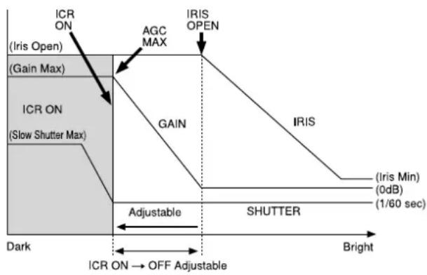
Auto ICR Mode
Auto ICR Mode automatically switches the settings needed for attaching or removing the IR Cut Filter.
With a set level of darkness, the IR Cut Filter is automatically disabled (ICR ON), and the infrared sensitivity is increased. With a set level of brightness, the IR Cut Filter is automatically enabled (ICR OFF).
Also, on systems equipped with an IR light, the internal data of the camera is used to make the proper decisions to avoid malfunctions.
Auto ICR Mode operates with the AE Full Auto setting.
When Auto Slow Shutter is Off (initial setting)

flowchart
graph TD
    A["ICR ON"] --> B["AGC MAX"]
    B --> C["IRIS OPEN"]
    C --> D["IRIS SHUTTER"]
    D --> E["Dark Bright"]
    F["ICR OFF → ON"] --> G["Shutter 1/60 sec"]
When Auto Slow Shutter is On
flowchart
graph TD
    A["ICR ON (Iris Open)"] --> B["IGC MAX"]
    B --> C["AGC MAX"]
    C --> D["IRIS OPEN"]
    D --> E["IRIS"]
    E --> F["(Iris Min) (0dB) (1/60 sec)"]
    F --> G["Adjustable"]
    G --> H["SHUTTER"]
    H --> I["Bright"]
    J["ICR ON (Slow Shutter Max)"] --> K["Dark"]
    L["IGC MAX"] --> M["Gain"]
    N["IGC MAX"] --> O["GAIN"]
    P["IGC MAX"] --> Q["IRIS"]
    R["IGC MAX"] --> S["Adjustable"]
    T["IGC MAX"] --> U["SHUTTER"]
    V["IGC MAX"] --> W["Bright"]
    X["IGC MAX"] --> Y["Adjustable"]
    Z["IGC MAX"] --> AA["Bright"]
Note
Depending on the information such as brightness, etc., in the ON/OFF settings condition, a malfunction may occur when the subjects largely consisting of blue and green colors are taken.
Camera ID
The ID can be set up to 65,536 (0000 to FFFF). As this will be memorized in the nonvolatile memory inside, data will be saved.
Picture Effect
It consists of the following functions.
• Neg. Art: Negative/Positive Reversal
- Black & White: Monochrome Image
PAN/TILT SLOW mode
When this function is set to ON, the PAN/TILT movement slows down, allowing you to easily shoot the subject that moves slowly.
Note
The low-speed motion image may appear to be shaking depending on the zoom factor.
Check for influence of installation environment on infrared remote commander operation
The supplied infrared remote commander may not operate, only occasionally, in the vicinity of the inverter lighting device. In this case, it is possible that the camera is installed in a place where the infrared remote commander cannot stably receive light due to the emission of light from the lighting device.
If the installation environment is judged to be unstable for operating the infrared remote commander, try to take such measures as to install this unit in a place away from the lighting device having the influence, and so on.
Others
STANDBY
Sends the power off command. Or when the power is turned off using the infrared remote commander, the camera becomes STANDBY state.
In the STANDBY state, the camera can accept only the VISCA Commands and the POWER ON of the infrared remote commander, and the video signal output and other operations are stopped.
I/F Clear
Clears the Command buffer of the camera. The buffer is cleared even during the power on state using the control software.
Memory (Preset)
Using the preset function, 256 sets of camera shooting conditions can be stored and recalled.
This function allows you to achieve the desired status instantly, even without adjusting the following items each time.
- Pan/Tilt Position
- Zoom Position
• Digital Zoom On/Off - Focus Auto/Manual
- Focus Position
- AE Mode
- Shutter control parameters
- Bright Control
- Iris control parameters
• Gain control parameters - Exposure Compensation On/Off
- Exposure Level
- Backlight Compensation On/Off
• Auto Slow Shutter On/Off - White Balance Mode
• R/B Gain - Aperture Control
- ICR On/Off
- WD Parameter
- Defog On/Off
The settings stored using this function are recalled when the power is turned on.
For setting items, see the "Initial Settings and Preset" section on page 10.
Note
Rewriting of memory is not unlimited. Be careful to avoid using the memory area for such as unnecessary tasks as rewriting the contents of the memory for every operation.
Initial Settings and Preset
- The initial values are the factory settings.
- When the power is turned on, this unit starts operation with the settings stored in preset 1.
- In “Preset 1 to 256”, the items that are preserved even after the power from the camera is turned off are indicated by a circle (O), and the items that are not preserved are indicated by a cross (×).
- When you send the CAM Memory Reset command, or select and press a position from POSITION1 to 6 while pressing the RESET button using the infrared remote commander, setting of the selected number will be initialized.
- The preset 1 is the CAM Memory number “0” in the VISCA command. The preset 2 to 16 are the CAM Memory number “1 to 15” in the VISCA command.
| Mode/Position setting Initial | settings Preset 1 Preset 2 to 256 | ||
| Pan/Tilt Position Home position | ○ | ○ | |
| Pan/Tilt Limit Position Maximum range of movement | ○ | × | |
| Zoom Position Wide end | ○ | ○ | |
| D-Zoom On/Off On | ○ | ○ | |
| Focus Position — | ○ | ○ | |
| Focus Auto/Manual Auto | ○ | ○ | |
| Near Limit Setting D000h (30 cm) | ○ | × | |
| AF Sensitivity | Normal | ○ | × |
| AF Mode | Normal | ○ | × |
| AF Run Time | 5 sec | ○ | × |
| AF Interval | 5 sec | ○ | × |
| WB Mode | Auto | ○ | ○ |
| WB Data (Rgain, Bgain) | — | ○ | ○ |
| One Push WB Data | — | ○ | × |
| AE Mode | Full Auto | ○ | ○ |
| WD Mode | Off | ○ | ○ |
| Auto Slow Shutter Mode | Off | ○ | ○ |
| Shutter Position | — | ○ | ○ |
| Iris Position | — | ○ | ○ |
| Gain Position | — | ○ | ○ |
| Bright Position | — | ○ | ○ |
| Exposure Compensation On/Off | Off | ○ | ○ |
| Exposure Compensation Amount | ±0 | ○ | ○ |
| BackLight On/Off Off | ○ | ○ | |
| Aperture Level | 0Ah | ○ | ○ |
| High Resolution Mode On/Off | Off | ○ | × |
| Picture Effect | Off | ○ | × |
| ICR On/Off | Off | ○ | ○ |
| Auto ICR On/Off | Off | ○ | × |
| Auto ICR Threshold Level | 0Eh | ○ | × |
| Image Stabilizer On/Off | Off | ○ | × |
| High Sensitivity Mode On/Off | Off | ○ | × |
| Gamma | 0:standard | ○ | × |
| Defog On/Off | Off | ○ | ○ |
| NR Level | 3 | ○ | × |
| Gain Limit | — | ○ | × |
| Low-Illumination Chroma Suppress | 2h (Middle) | ○ | × |
| Color Gain | 4h (100%) | ○ | × |
| Color Hue | 7h (0degrees) | ○ | × |
Notes
- The execution of memory to the preset is limited.
- When turning the power off and on again, if you want to reflect the camera conditions and pan/tilt position that are set before the power is turned off, store the settings in POSITION1.
- The setting or deleting of memory to/from preset 1 takes approx. 2 seconds longer than other channels.
- In CameraID, the data is stored regardless of the preset.
- When ImageFlip is executed, all presets are reset to the initial value.
- The CAM_Memory command is enabled only for presets 1 to 16.
Mode Condition
Basic settings
| Command\Mode | Power Off1) | Power On | ||||||
| IFC2) | Initializing3) | During displaying the menu | Memory Command | OnePushWB VideoFormatChange Pan-TiltReset | ||||
| Address Set Yes Yes Yes Yes Yes Yes Yes | ||||||||
| IF_Clear Yes | 6) | Yes6) | Yes6) | Yes6) | Yes6) | Yes6) | Yes6) | Yes6) |
| CAM_Power On Yes No No Yes | No Yes | No Yes | ||||||
| CAM_Power Off | Yes | No | No | Yes | No | Yes | No | Yes |
| CAM_VersionInq | Yes Yes | Yes 4) | Yes Yes Yes Yes Yes | |||||
| CAM_PowerInq | Yes Yes | Yes Yes Yes | Yes Yes Yes | |||||
| InquiryCommand | No No | No | Yes | 5) | No | No | No Yes | |
1) DC power is being supplied, but the camera has been turned off by a VISCA command.
2) The period from the time IF Clear is sent, until the Reply Packet is returned.
3) The period from the time DC power is turned on or the camera is turned on via a VISCA command, and the camera subsequently finishes the pan/tilt reset operation
and stops at the Home position, until the video signal is output. Or the period from the time the CAM Power ON command is sent, until Completion is returned.
4) Commands can be executed after the pan/tilt movement has be
5) When the menu display is updating, operation is not p
6) Although the command is received, it is not executed.
Output settings
| Command\Mode | Power Off | Power On | |||||||||
| IFC | Initializing | PanTilt | PanTilt ABS | PanTilt Rel | ZoomDirect | Focus Direct | Recall | During displaying the menu | OnePush WB | ||
| CAM_VideoFormatChange (Execution of the VISCA command from user during the VISCA mode) | No | No | No | No | No | No | No | No | No | Yes 1) | No |
1) The Video Format state of MENU is not updated. Close MENU once, and then display it again. Other commands are not received while executing Format Change.
Zoom/Focus
| Command\Mode | Power Off1) | Power On | |||||||
| IFC2) | Initializing3) | Zoom Direct Focus Direct AF ON | During displaying the menu | Memory Recall | Memory FormatChange | ||||
| CAM_Zoom Tele/Wide/Stop [VISCA] No | No No No Yes Yes Yes | 4) | No No | ||||||
| CAM_Zoom Tele/Wide/Stop [Infrared Remote Commander] | No No No Yes Yes Yes | 4) | No No | ||||||
| CAM_Zoom Direct No No No Yes Yes Yes Yes | 4) | No No | |||||||
| D-Zoom Limit No No No Yes Yes Yes | 4) | No No | |||||||
| CAM_Focus Far/Near/Stop [VISCA] | No No No Yes No | No Yes | 4) | No No | |||||
| CAM_Focus Far/Near/Stop [Infrared Remote Commander] | No No No Yes No | No Yes | 4) | No No | |||||
| CAM_Focus Direct | No No No Yes Yes No | Yes | 4) | No No | |||||
| CAM_Focus Mode (Auto/Manual) | No | No | No | Yes | No | Yes | Yes4) | No No | |
| CAM_Focus One Push Trigger | No | No | No | Yes | No | No | Yes4) | No No | |
| CAM_Focus Infinity | No No No Yes No | Yes Yes | 4) | No No | |||||
| CAM_Focus Near Limit | No | No | No | Yes | No | Yes | Yes4) | No No | |
| AF Sensitivity Normal/Low | No No No Yes Yes Yes | 4) | No No | ||||||
| AF Mode Norm/Interval/Zoom | No | No | No | Yes | Yes | Yes | Yes4) | No No | |
| AF Activation Time/Interval Setting | No No No Yes Yes Yes Yes | 4) | No No | ||||||
1) DC power is being supplied, but the camera has been turned off by a VISCA command.
2) The period from the time IF Clear is sent, until the Reply Packet is returned.
3) The period from the time DC power is turned on or the camera is turned on via a VISCA command, and the camera subsequently finishes the pan/tilt reset operation and stops at the Home position, until the video signal is
output. Or the period from the time the CAM Power ON command is sent, until Completion is returned.
4) When the menu display is updating, operation is not possible.
White Balance
| Command\Mode | Power Off1) | Power On | |||||||||
| IFC2) | Initializing3) | White balance mode | During displaying the menu | Memory Recall | |||||||
| Auto | Indoor | Outdoor | One Push | Manual | ATW | ||||||
| CAM_WB Auto/Indoor/Outdoor/OnePhshWB/Manual/ATW | No | No | No | Yes | Yes | Yes | Yes | Yes | Yes | Yes4) | No |
| CAM_WB One Push Trigger | No | No | No | No | No | No | Yes5) | No | No | Yes4) | No |
| CAM_WB R(B) Gain Reset/Up/Down/Direct | No | No | No | No | No | No | No | Yes | No | Yes4) | No |
1) DC power is being supplied, but the camera has been turned off by a VISCA command.
2) The period from the time IF Clear is sent, until the Reply Packet is returned.
3) The period from the time DC power is turned on or the camera is turned on via a VISCA command, and the camera subsequently finishes the pan/tilt reset operation and stops at the Home position, until the video signal is output. Or the period from the time the CAM Power ON command is sent, until Completion is returned.
4) When the menu display is updating, operation is not possible.
5) Commands are ignored during a One Push AWB operation.
Exposure
| Command\Mode | Power Off 1) | Power On | |||||||||
| IFC 2) | Initializing 3) | Exposure mode | During displaying the menu | Memory Recall | |||||||
| Full Auto WIDE D Off | Full Auto WIDE D Low/ Mid/High | Bright | Shutter Pri | Iris Pri Manual | |||||||
| CAM_AE Full Auto/Manual/Shutter Pri/ Iris Pri | No No No Yes No Yes | 4) | Yes Yes | Yes Yes | 5) | No | |||||
| CAM_AE Bright No No No Yes No Yes | Yes No No Yes | 5) | No | ||||||||
| CAM_Slow Shutter ON/OFF No No No | Yes No Yes Yes Yes Yes Yes | 5) | No | ||||||||
| CAM_Shutter Reset/Up/Down/Direct | No No No No No Yes Yes Yes | 5) | No | ||||||||
| CAM_Iris Reset/Up/Down/Direct No | No No No No Yes Yes | 5) | No | ||||||||
| CAM_Gain Reset/Up/Down/Direct No | No No No No No Yes Yes | 5) | No | ||||||||
| CAM_Bright/Up/Down/Direct | No No No No Yes No Yes | 5) | No | ||||||||
| CAM_ExComp On/Off | No No No Yes | Yes Yes Yes Yes Yes Yes | 5) | No | |||||||
| CAM_ExComp Reset/Up/Down/ Direct 6) | No No No Yes | Yes Yes Yes Yes Yes Yes | 5) | No | |||||||
| CAM_Backlight On/Off | No | No | Yes | Yes | Yes | No | No | No | No | Yes 5) | No |
| CAM_WIDE_D Off/Low/Mid/High | No | No | Yes | Yes | Yes | No | No | No | No | Yes 5)(7) | No |
| CAM_Defog | No No No Yes | Yes Yes Yes Yes Yes Yes | 7) | No | |||||||
1) DC power is being supplied, but the camera has been turned off by a VISCA command.
2) The period from the time IF Clear is sent, until the Reply Packet is returned.
3) The period from the time DC power is turned on or the camera is turned on via a VISCA command, and the camera subsequently finishes the pan/tilt reset operation and stops at the Home position, until the video signal is output. Or the period from the time the CAM Power ON command is sent, until Completion is returned.
4) Yes: Only when the camera changes to BRIGHT mode from Full Auto or SHUTTER Pri mode.
5) When the menu display is updating, operation is not possible.
6) No: This is not allowed when EX-COMP is set to OFF.
7) This can be changed only when the exposure control mode is Full Auto.
Effect
1) DC power is being supplied, but the camera has been turned off by a VISCA command.
2) The period from the time IF Clear is sent, until the Reply Packet is returned.
3) The period from the time DC power is turned on or the camera is turned on via a VISCA command, and the camera subsequently finishes the pan/tilt reset operation and stops at the Home position, until the video signal is output. Or the period from the time the CAM Power ON command is sent, until Completion is returned.
4) When the menu display is updating, operation is not possible.
Pan/Tilt
| Command | Mode | Power Off1) | Power On | |||||||||||||||
| IFC2) | Initia-lizing3) | Zoom (Direct) | Focus (Direct) | Pan/tilt movement according to the command4) | Absolute Position execution | Relative Position execution | Home execution | Reset execution M | Memory Recall | During displaying the menu | Position detection error | |||||||
| Transmit device | Common | Common | VISCA | Infrare Remote Commander | VISCA | VISCA VISCA | VISA | Infrare Remote Commander | VISCA | Infrare Remote Commander | VISCA | Infrare Remote Commander | ||||||
| Pan-tiltDrive Up/Down/Left/Right/UpLeft/UpRight/DownLeft/DownRight | VISCA No | No No | Yes Yes | Yes Yes | No No No | No No No | No No No | Yes | 10) | Yes8) | ||||||||
| Infrare Remote Commander | No No | No Yes | Yes Yes | No No No | No No No | No No No | No No Yes | 8) | ||||||||||
| Pan-tiltDrive Stop | VISCA | No | No | No | Yes | Yes | Yes | Yes | No | No | No | No | No | No | No | No | No | Yes |
| Pan-tiltDrive AbsolutePosition | VISCA | No | No | No | Yes | Yes | No | No | Yes | No | No | No | No | No | No | No | Yes5) | No |
| Pan-tiltDrive RelativePosition | VISCA No | No No | Yes Yes | No | No No No | No No No | No No No | No Yes | 5) | Yes | ||||||||
| Pan-tiltDrive Home | VISCA No | No No | Yes Yes | No | No No No | Yes No No | No No No | No Yes | No | |||||||||
| Infrare Remote Commander | No No | No Yes | Yes | No No No | No No No | Yes No | No No No | No No | ||||||||||
| Pan-tiltDrive Reset | VISCA No | No No | Yes Yes | No | No No No | No No No | No No No | No Yes | 5) | Yes | ||||||||
| Infrare Remote Commander | No No | No Yes | Yes | No No No | No No No | No No No | No Yes | 5) | Yes | |||||||||
| Pan-tiltLimitSet LimitSet | VISCA No | No No | Yes Yes | Yes | 9) | Yes 9) | No No No No | No No No | No No | Yes | 5) | No | ||||||
| Pan-tiltLimitSet LimitClear | VISCA No | No No | Yes Yes | Yes | 9) | Yes 9) | No No No No | No No No | No No | Yes | 5) | No | ||||||
| Memory Set | Common | No | No | No | No | No | No | No | No | No | No | No | No | No | No | No | No | No |
| Memory Reset | Common | No | No | No | No | No | Yes | Yes | No | No | No | No | No | No | No | No | No | No |
| Memory Recall | VISCA No | No No | No | 6) | No 7) | No No No No No | No No No Yes | Yes | No Yes | Yes | ||||||||
| Infrare Remote Commander | No No | No | No | 6) | No 7) | No No No No No | No No No Yes | Yes | No Yes | Yes | ||||||||
| Pan-tiltSetSlowPanTilt | VISCA No | No No | Yes Yes | Yes | 9) | Yes 9) | No No No No | No No No | No No | Yes | No | |||||||
1) DC power is being supplied, but the camera has been turned off by a VISCA command.
2) The period from the time IF Clear is sent, until the Reply Packet is returned.
The period from the time DC power is turned on or the camera is turned on via a VISCA command, and the camera subsequently finishes the pan/tilt reset operation and stops at the Home position, until the video signal is output.
4) The pan/tilt operation works by Pan-tiltDrive Up/Down/Left/Right/UpLeft/UpRight/DownLeft/DownRight commands.
5) When the menu display is updating, operation is not possible.
6) Yes: while the camera operates in Tele/Wide zoom mode.
7) Yes: while the camera operates in Far/Near focus mode.
8) Yes: only for movements away from the direction where a position detection error has been recognized.
9) The setting is reflected after the drive has stopped.
10) Although Ack/Comp is returned, the pan/tilt operation is not performed.
Command List
VISCA 1) RS-422
Commands
Use of RS-422 control software based upon this command list may cause malfunction or damage to hardware and software. Sony Corporation is not liable for any such damage.
Overview of VISCA
In VISCA, the device outputting the commands, for example, a computer, is called the controller, while the device receiving the commands, such as this unit, is called the peripheral device. In VISCA, up to seven peripheral devices can be connected to one controller using communication conforming to the RS-422 standard. The parameters of RS-422 are as follows.
- Communication speed: 9600 bps/38400 bps
- Data bits : 8
- Start bit : 1
- Stop bit : 1
- Non parity
Flow control using XON/XOFF and RTS/CTS, etc., is not supported.
Note
For this camera, one controller can be connected to one SRG-360SHE/SRG-280SHE. To connect multiple SRG-360SHE/SRG-280SHE devices, use VISCA over IP. For the use of VISCA over IP, refer to “VISCA over IP” (page 22).
VISCA Communication Specifications
VISCA packet structure
The basic unit of VISCA communication is called a packet (Fig. 2). The first byte of the packet is called the header and comprises the sender's and receiver's addresses. The value of the header is fixed as 81h, as only one camera can be operated from the controller via the RS-422 connection for this camera. In the command list, this is indicated as 8X. Replace this "X" with the SRG address appropriately (for this camera, this is locked to 1). The header of reply packet is 90h.
When the terminator is FFh, it signifies the end of the packet.

Fig. 2 Packet structure
1) The maximum length of the message is 15 bytes (the maximum length of the packet is 17 bytes) only for commands to set the camera position.
Note
Fig. 2 shows the packet structure, while Fig. 3 shows the actual waveform. Data flow will take place with the LSB first.

Fig. 3 Actual waveform for 1 byte.
Timing Chart
If two or more commands are to be sent successively, wait for a reply command (an Acknowledge or error message for a general command, and an inquiry packet for an inquiry command) of the previous command to be received before sending the next command.
Controller Peripheral devices

flowchart
graph TD
    A["Command1"] --> B["Acknowledge of Command1"]
    A --> C["Completion of Command1"]
    A --> D["Acknowledge of Command2"]
    A --> E["Completion of Command2"]
    F["Command2"] --> A
    G["Be sure to wait for Acknowledge of Command1 before issuing Command2."] --> A
Command and inquiry
- Command
Sends operational commands to this unit.
- Inquiry
Used for inquiring about the current state of this unit.
Command Packet Note
| Inquiry 8X QQ RR ... FF QQRR | 1) = Command/Inquiry, 2) = category code |
| 1) QQ = 01 (Command), 09 (Inquiry) | |
| 2) RR = 00 (Interface), 04 (camera 1), 06 (Pan/Tilter) | |
| Locked to X=1 for this camera. | |
For actual values to be sent, see Command Lists or Inquiry Command Lists.
Responses for commands and inquiries
● Acknowledge message
A message returned by this unit when it receives a command. No Acknowledge message is returned for an inquiry, cancel, or device setting command.
● Completion message
A message returned by this unit when the execution of command or inquiry is completed. In the case of inquiry commands, reply data for the inquiry is contained after the 3rd byte of the packet. If the Acknowledge message is omitted, the socket number will contain 0.
Reply Packet Note
Acknowledge X0 4Y FF Y = socket number
Completion (Commands) X0 5Y FF Y = socket number
Completion (Inquiries) X0 5Y ... FF Y = socket number
Locked to X=9 for this camera.
- Error message
When a command could not be executed or failed, an error message is returned instead of an Acknowledge message. In some commands (such as zoom) in which the process is not completed immediately after the Acknowledge message, an error message may be returned after an Acknowledge message. When an inquiry command could not be executed or failed, an error message is returned instead of a completion message.
Error Packet
Description
| X0 6Y 01 FF | Message length error |
| X0 60 02 FF | Syntax Error |
| X0 60 03 FF | Command buffer full |
| X0 6Y 04 FF | Command canceled |
| X0 6Y 05 FF | No socket (to be canceled) |
| X0 6Y 41 FF | Command not executable |
| Locked to X=9 for this camera. | |
Socket number
This unit has two sets of sockets (buffers) for commands, so that up to two commands including the commands currently being executed can be received. When this unit receives commands, it notifies the sender which socket was used, using the socket number of the Acknowledge message. As each of the completion message and error message also has a socket number, you can identify which command has ended.
When sending the commands continuously, be sure to wait until an Acknowledge message or error message of the first command is returned, then send the next command. (Otherwise, it is impossible to identify to which command the socket number belongs.)
Even when two sockets are being used, the device setting commands and some inquiry messages can be executed.
The Acknowledge message is not returned for these commands and inquiries, and only the completion message of socket number 0 is returned.
Command execution cancel
To cancel a command which has already been sent, send a Cancel command as the next command.
Cancel Packet Note
Cancel 8X 2Y FF Y = socket number
Locked to X=1 for this camera.
Error message “Command canceled” will be returned for this command, but this is not a fault. It indicates that the command has been canceled.
VISCA Device Setting Command
Before starting control of this unit, be sure to send the Address command and the IF_Clear command using the broadcast function.
For VISCA network administration
- Address\*
Sets an address of a peripheral device. Use when initializing the network, and receiving the following network change message.
* Not available for VISCA over IP.
● Network Change\*
Sent from the peripheral device to the controller when a device is removed from or added to the network. The address must be re-set when this message is received.
* Not available for VISCA over IP.
Packet Note
Address 88 30 01 FF Always broadcasted.
Network Change X0 38 FF
Locked to X=9 for this camera.
VISCA interface command
- IF\_Clear
Clears the socket in the SRG. When cleared, the operation currently being executed is not guaranteed.
| Command Packet | Reply Packet | Note |
| IF_Clear | 8X 01 00 01 FF | Z0 50 FF |
| IF_Clear (broadcast)1) | 88 01 00 01 FF | 88 01 00 01 FF |
Locked to X=1 for this camera.
Locked to Z=9 for this camera.
1) The broadcast function is not available for VISCA over IP.
VISCA interface and inquiry
● CAM\_VersionInq
Returns information on the VISCA interface.
Inquiry Inquiry Packet Reply Packet Description
CAM_VersionInq 8X 09 00 02 FF Y0 50 GG GG HH HH JJ JJ KK FF GGGG = Vender ID
(0001: Sony)
HHHH = Model ID
(0604: SRG-360SHE)
(0605: SRG-280SHE)
JJJJ = ROM revision
KK = Maximum socket # (02)
Locked to X=1 for this camera.
Locked to Y=9 for this camera.
VISCA Command/Acknowledge Protocol
| Command Command | Message Reply Message Comments | ||
| General Command | 81 01 04 38 02 FF (Example) | 90 41 FF (Acknowledge)+90 51 FF (Completion)90 42 FF 90 52 FF | Returns Acknowledge when a command has been accepted, or Completion when a command has been executed. |
| 81 01 04 38 FF (Example) | 90 60 02 FF (Syntax Error) | Accepted a command which is not supported or a command lacking parameters. | |
| 81 01 04 38 02 FF (Example) | 90 60 03 FF(Command Buffer Full) | Could not accept the command as there are two commands currently being executed. | |
| 81 01 04 08 02 FF (Example) | 90 61 41 FF(Command Not Executable)90 62 41 FF | Could not execute the command in the current mode. | |
| Inquiry Command | 81 09 04 38 FF (Example) | 90 50 02 FF (Completion) | Does not return Acknowledge. |
| 81 09 05 38 FF (Example) | 90 60 02 FF (Syntax Error) | Accepted an incompatible command. | |
| Command Cancel | 81 22 FF(Example) | 90 62 04 FF(Command Canceled) | Returned when the command of the socket specified is canceled. Completion for the command canceled is not returned. |
| 90 62 05 FF (No Socket) | Returned when the command of the specified socket has already been completed or when the socket number specified is wrong. | ||
| Address Set 1) | 88 30 01 FF | 88 30 02 FF | The device address number plus 1 is returned. |
| IF_Clear (Broadcast) 1) | 88 01 00 01 FF | 88 01 00 01 FF | The same command is returned. |
| IF Clear(for device address 1) | 81 01 00 01 FF(Example) | 90 50 FF (Completion) | Acknowledge is not returned for this command. |
1) Not available for VISCA over IP.
Acknowledge/Completion Messages
| Command Command Message Comments | ||
| Acknowledge z0 4y FF | (y: Socket No.) | Returned when the command is accepted. |
| Completion z0 5y FF | (y: Socket No.) | Returned when the command has been executed. |
Locked to Z=9 for this camera
Error Messages
| Command Command Message Comments | ||
| Syntax Error z0 60 02 FF Returned when the format is different or | when a command with illegal parameters is accepted. | |
| Command Buffer Full z0 60 03 FF Could not accept a command that is received while two commands are currently being executed (two sockets have been used). | ||
| Command Canceled z0 6y 04 FF(y: Socket No.) | Returned when a command which is being executed in a socket specified by the cancel command is canceled. The completion message for the command is not returned. | |
| No Socket z0 6y 05 FF(y: Socket No.) | Returned when no command is executed in a socket specified by the cancel command, or when an invalid socket number is specified. | |
| Command Not Executable z0 6y 41 FF(y: Socket No.) | Returned when a command cannot be executed due to current conditions. For example, when a command for controlling the manual focus is received during the auto focus mode. | |
Locked to Z=9 for this camera
Network Change Message*
| Command Command Message Comments | |
| Network Change z0 38 FF Issued when power is supplied to the camera. | |
Locked to Z=9 for this camera
* Not available for VISCA over IP.
VISCA over IP
Overview of VISCA over IP
VISCA over IP allows you to control this unit from the controller with the IP communication function via the LAN by using VISCA.
You can connect up to 5 controllers simultaneously on the network.
The communication specifications of VISCA over IP are as follows:
- Interface
RJ-45 10Base-T/100Base-TX (automatically discrimination)
- Internet protocol
IPv4
- Transport protocol
UDP
- IP address
Set by the IP card setting command
- Port address
52381
- Delivery confirmation/Retransmission control
Depends on the application
In this section, the device outputting commands, for example, a computer, is called the controller, and this unit and the devices connected to the same LAN are called the peripheral device. In the connection using RS-232/RS-422, the controllers and peripheral devices are connected to a one-direction ring. On the IP communication connection, the controllers and peripheral devices are connected by star type through a LAN.
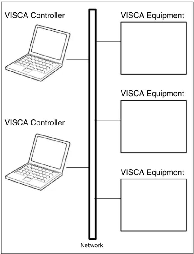
IP communication connection
While the IP communication connection, the address of each device cannot be set in the VISCA message as it is because the controllers and peripheral devices that are connected simultaneously are increased. In this case, addresses of the controllers and peripheral devices that are set in the VISCA message are locked to 0 (for the controller) or 1 (for the peripheral device).
For details of the IP address setting procedure, see “IP Related Setting Command” (page 26).
Communication method of VISCA over IP
Communication method
VISCA over IP can process the VISCA communication between the controllers and peripheral devices using the messages that can be identified on the LAN, and sends/receives them. Because of this, VISCA over IP is not concerned about the contents of the communication between the controllers and peripheral devices. However, the VISCA communication sequence is different, depending on the types, as follows.
VISCA command
This is a command from the controller to the peripheral device.
When the peripheral device receives this command, Acknowledge is returned. After completing command processing, a completion notice is returned. This command uses the socket of VISCA. The order of completion notices may be changed if the multiple commands are sent to the same peripheral device.
VISCA inquiry
This is an inquiry from the controller to the peripheral device.
When the peripheral device receives this type of command, the reply for the inquiry is returned. This command does not use the socket of VISCA. The order of the replies is not changed if a multiple commands are sent.
VISCA reply
This is an Acknowledge, completion notice, reply, or error reply from the peripheral device to the controller. The classification for sending messages from the peripheral device to the controller is common.
VISCA device setting command
This is the device setting command from the controller to the peripheral device.
When the peripheral device receives this classifications command, the peripheral device performs the function depend on the command.
- Address
Sets the address of the peripheral device, and does not return a reply to the controller. While using VISCA over IP, the address command is not sent from the controller because a Network Change command from the peripheral device that triggers sending command is not issued.
- IF\_Clear
Sends the reply message to the controller after clearing, without using VISCA socket.
- CAM\_VersionInq
Sends the reply message to the controller, without using VISCA socket.
Format
These are the specifications of the message header (8 bytes) and payload (1 to 16 bytes).

Message structure
Note
The actual LAN out method is big-endian, LSB first.
Payload type
Stores the value (Byte 0 and Byte 1) of the following table on the payload division.
| Name Value (Byte 0) Value (Byte 1) Description | ||
| VISCA command 01h 00h Stores the VISCA command. | ||
| VISCA inquiry 01h 10h Stores the VISCA inquiry. | ||
| VISCA reply 01h 11h Stores the reply for the VISCA command and VISCA inquiry,or VISCA device setting command. | ||
| VISCA device setting command | 01h 20h Stores the VISCA device setting command. | |
| Control command 02h 00h Stores the control command. | ||
| Control reply 02h 01h Stores the reply for the control command. | ||
Payload length
Stores the number of bytes (1 to 16) of data is stored on the payload.
Example: When the payload length is 16 bytes.
Byte 2:00h
Byte 3:10h
Sequence number
The controller stores the sequence number that is added every time a message is sent. If the sequence number reaches the limit, next value will be 0. The peripheral device saves the sequence number in the message from the controller, and stores the sequence number of the received message corresponding to the message sent to the controller.
Payload
Depending on the payload type, the following are stored.
• VISCA command
Stores the packet of the VISCA command.
• VISCA inquiry
Stores the packet of VISCA message.
• VISCA reply
Stores the reply for the command or inquiry (Acknowledge message, completion message, or error message).
• VISCA device setting command
Stores the packet of the VISCA device setting command.
- Control command
The following are stored on the payload division of the control command.
| Name Value Description | ||
| RESET 01h Resets | the sequence number to 0. The value that was set as the sequence number is ignored. | |
| ERROR 0Fyyh yy=01: Abnormality in the sequence number. | ||
- Controlled reply
The following are stored on the payload division of the reply for the control command.
| Message | Value Description | |
| Acknowledge | 01h Reply for | RESET. |
Delivery confirmation
VISCA over IP uses UDP as a communications protocol of the transport layer. Delivery of messages is not guaranteed for the UDP communication. Delivery confirmation and retransmission should be performed on the application.
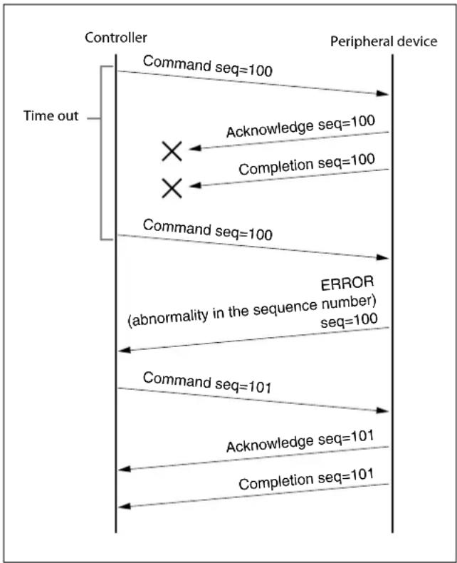
When the controller sends a message to the peripheral device, wait until a reply for the message is received before sending the next message. You can confirm delivery of messages by managing the time-out waiting for a reply message sent.
If time out occurs on the controller, loss of one of the following messages is considered:
- Command
- Acknowledge message
•Completion message for the command
•Inquiry
• Reply message for the inquiry
- Error message
- Inquiry of the VISCA device setting command
- Reply message of the VISCA device setting command
If time out occurs on the controller, you can infer the lost message and state of the peripheral device by retransmitting the message using the same sequence number. The following table shows the received message and status by retransmission of the lost message, and the reference of correspondence after retransmission for each case. (Except for the case that a time out occurs for reasons other than loss of message.)
| Lost message Received message for retransmission | Status after retransmission Correspondence after retransmission | ||
| Command Acknowledge message | Command is performed by retransmission. | Continue processing. | |
| Acknowledge message ERROR | (Abnormality in the sequence number.) | Command has been performed.If only the Acknowledgement message is lost, the completion message returns. | If the result by the completion message is needed,retransmit by updating the sequence number. |
| Completion message for the command | ERROR (Abnormality in the sequence number.) | Command has been performed. | If the result by the completion message is needed,retransmit by updating the sequence number. |
| Inquiry Reply message Inquiry | is performed by retransmission. | Continue processing. | |
| Reply message for the inquiry | ERROR (Abnormality in the sequence number.) | Inquiry has been performed. If there result by the reply message is needed,retransmit by updating the sequence number. | |
| Error message Error message | Command is not performed. If the error cause eliminates, normal reply is returned.(Acknowledge, reply message). | Eliminate the error cause. If normal reply returns, continue processing. | |
| Inquiry of the VISCA device setting command | Reply message of the VISCA device setting command | Inquiry has been performed by retransmission. | Continue processing. |
| Reply message of the VISCA device setting command | ERROR (Abnormality in the sequence number.) | Inquiry has been performed. If there result by the reply message is needed,retransmit by updating the sequence number. | |
This unit has 2 sockets for the command to deal with advanced uses. When using VISCA over IP, up to 2 commands (including the current command) can be received. Depending on the message from the controller to the peripheral device, there are some messages that do not need to guarantee delivery. However, the peripheral device receives commands from multiple controllers while connected to VISCA over IP. If the multiple commands are sent without waiting for the reply, the possibility of non-execution of the command and errors due to socket overflow become high, because of limitations of order to receive commands or execution interval of command. It may reduce the substantial efficiency.
Timing chart

flowchart
graph TD
    A["Time out"] --> B["Controller"]
    B --> C["Peripheral device"]
    B --> D["Command seq=100"]
    D --> E["X"]
    B --> F["Command seq=100"]
    F --> G
    B --> H["Acknowledge seq=100"]
    H --> I
    B --> J["Completion seq=100"]
    J --> K
Timing chart (loss of command)
flowchart
graph TD
    A["Controller"] -->|Command seq=100| B["Peripheral device"]
    B -->|Acknowledge seq=100| A
    A -->|Completion seq=100| B
    B -->|Command seq=100| A
    A -->|ERROR (abnormality in the sequence number) seq=100| B
    B -->|Command seq=101| A
    A -->|Acknowledge seq=101| B
    B -->|Completion seq=101| A
    A -->|Time out| A
Timing chart (loss of Acknowledge or completion message)
IP Related Setting Command
The following commands are provided for setting the IP address and name of this unit.
| No. Name Description | ||
| 1 Setting | Protocol:Inquiry | The controller inquires the network setting for the camera. |
| 2 Setting | Protocol:Inquiry reply | The camera replies according to the inquiry from the controller. |
| 3 Setting | Protocol:Network setting | The controller sets the network setting of the camera. |
| 4 Setting | Protocol:Network setting reply | The camera replies according to the network setting of the controller. |
The network setting of the IP card is performed as communication sequence in the following.
1 Inquiry
The controller sends the inquiry packet to the broadcast address (255.255.255.255), specified port number (52380) of UDP. The IP card replies as the inquiry reply packet.
2 Network setting
The controller sends the network setting packet to the broadcast address (255.255.255.255), specified port number (52380) of UDP. The receiving side sees the MAC address unit in the packet, and returns Acknowledge as the network setting reply if it is the request for the receiving side.
Note
This camera requires up to 30 sec. to reflect the settings, after sending the network setting responses. Make sure to send the next network setting command after 30 sec. passes. If this camera receives network command during this 30 sec from controller, this camera returns the setting response data with NAK set.
| Command Data | |
| Inquiry | 02ENQ:network1) |
| UDP | FF |
| Broadcast address(255.255.255.255) | 03 |
| Specified port number(52380) | |
| Inquiry reply | 02MAC:**-**-**-**-**-**1) |
| UDP | FF |
| Broadcast address(255.255.255.255) | MODEL:IPCARD1) |
| Specified port number(52380) | FFSOFTVERSION:**.**.**1) |
| FFIPADR:***.***.***.***1) | |
| FFMASK:***.***.***.***1) | |
| FFGATEWAY:***.***.***.***1) | |
| FFNAME:xxxxxxxxx1) | |
| FFWRITE:on1) | |
| FF03 | |
| Network setting | 02MAC:**-**-**-**-**-**1) |
| UDP | FF |
| Broadcast address(255.255.255.255) | IPADR:***.***.***.***1) |
| Specified port number(52380) | FFMASK:***.***.***.***1) |
| FFGATEWAY:***.***.***.***1)4) | |
| FFNAME:xxxxxxxxx1) | |
| FF03 | |
| Network setting reply | 02ACK:**-**-**-**-**-**2) |
| UDP | “xxxx”3) |
| Broadcast address(255.255.255.255) | FF |
| Specified port number(52380) | 03 |
1) Uses the ASCII code.
2) Uses the ASCII code. When the network setting has failed, returns as "NAK:**-**-**-**-**-**".
3) Uses the ASCII code. Returns by adding the detail message, if necessary. There may not be it.
4) When GATEWAY is not used, sends as “GATEWAY:0.0.0.0 FF”.
Note
A maximum of 8 characters including alphanumeric characters and blanks can be used for the name.
SRG-360SHE/SRG-280SHE Commands
Execution Command List (1/4)
| Command Set Command | Command Packet Comments | ||
| AddressSet Broadcast 88 30 | 01 FF Address setting | ||
| IF_Clear Broadcast 88 01 00 | 01 FF I/F Clear | ||
| CommandCancel — 8x 2p FF p: Socket No. (=1or2) | |||
| CAM_Power On 8x 01 04 00 | 02 FF Power ON/OFF | ||
| Off 8x 01 04 00 03 FF | |||
| CAM_Zoom | Stop | 8x 01 04 07 00 FF Zoom Control | |
| Tele (Standard) | 8x 01 04 07 02 FF | ||
| Wide (Standard) | 8x 01 04 07 03 FF | ||
| Tele (Variable) | 8x 01 04 07 2p FF | p=0 (Low) to 7 (High) | |
| Wide (Variable) | 8x 01 04 07 3p FF | ||
| Direct | 8x 01 04 47 0p 0q 0r 0s FF | pqrs: Zoom Position | |
| CAM_DZoom | On 8x 01 04 06 02 FF Digital zoom ON/OFF | 3) | |
| Off 8x 01 04 06 03 FF | |||
| CAM_Focus | Stop | 8x 01 04 08 00 FF Focus Control | |
| Far (Standard) | 8x 01 04 08 02 FF | ||
| Near (Standard) | 8x 01 04 08 03 FF | ||
| Far (Variable) | 8x 01 04 08 2p FF | p=0 (Low) to 7 (High) | |
| Near (Variable) | 8x 01 04 08 3p FF | ||
| Direct | 8x 01 04 48 0p 0q 0r 0s FF | pqrs: Focus Position | |
| Auto Focus 8x 01 04 38 02 FF AF ON/OFF | |||
| Manual Focus | 8x 01 04 38 03 FF | ||
| Auto/Manual | 8x 01 04 38 10 FF | ||
| One Push 'Trigger | 8x 01 04 18 01 FF | One Push AF Trigger | |
| Infinity | 8x 01 04 18 02 FF Forced infinity | ||
| Near Limit | 8x 01 04 28 0p 0q 0r 0s FF | pqrs: Focus Near Limit Position | |
| AF Sensitivity | Normal | 8x 01 04 58 02 FF AF Sensitivity High/Low | |
| Low | 8x 01 04 58 03 FF | ||
| CAM_AFMode | Normal AF | 8x 01 04 57 00 FF AF Movement Mode | |
| Interval AF 8x 01 04 57 01 FF | |||
| Zoom Trigger AF | 8x 01 04 57 02 FF | ||
| Active/Interval Time | 8x 01 04 27 0p 0q 0r 0s FF | pq: Movement Time, rs: Interval | |
| CAM_IRCorrection | Standard | 8x 01 04 11 00 FF | FOCUS IR Correction setting |
| IR Light | 8x 01 04 11 01 FF | ||
| CAM_ZoomFocus | Direct | 8x 01 04 47 0p 0q 0r 0s0t 0u 0v 0w FF | pqrs: Zoom Positiontuvw: Focus Position |
| CAM_WB | Auto | 8x 01 04 35 00 FF Normal Auto | |
| Indoor | 8x 01 04 35 01 FF Indoor mode | ||
| Outdoor | 8x 01 04 35 02 FF Out door mode | ||
| One Push WB | 8x 01 04 35 03 FF One Push WB mode | ||
| ATW | 8x 01 04 35 04 FF Auto Tracing White Balance | ||
| Manual | 8x 01 04 35 05 FF | Manual Control Mode | |
| One Push 'Trigger1) | 8x 01 04 10 05 FF One Push WB Trigger | ||
| CAM_RGain | Reset | 8x 01 04 03 00 FF Manual Control of RGain | |
| Up | 8x 01 04 03 02 FF | ||
| Down | 8x 01 04 03 03 FF | ||
| Direct | 8x 01 04 43 00 00 0p 0q FF | pq: R Gain | |
| CAM_BGain | Reset | 8x 01 04 04 00 FF Manual Control of BGain | |
| Up | 8x 01 04 04 02 FF | ||
| Down | 8x 01 04 04 03 FF | ||
| Direct | 8x 01 04 44 00 00 0p 0q FF | pq: B Gain | |
Execution Command List (2/4)
| Command Set Command | Command Packet Comments | ||
| CAM_AE Full Auto 8x 01 04 | 39 00 FF Automatic Exposure mode | ||
| Manual 8x 01 04 39 03 FF Manual Control mode | |||
| Shutter Priority 8x 01 04 39 0A FF Shutter priority Exposure mode | |||
| Iris Priority 8x 01 04 39 0B FF Iris priority Exposure mode | |||
| Bright2) | 8x 01 04 39 0D FF Bright Mode(Manual control) | ||
| CAM_SlowShutter Auto 8x | 01 04 5A 02 FF Auto Slow Shutter ON/OFF | ||
| Manual 8x 01 04 5A 03 FF | |||
| CAM_Shutter Reset | 8x 01 04 0A 00 FF Shutter Setting | ||
| Up | 8x 01 04 0A 02 FF | ||
| Down 8x 01 04 0A 03 FF | |||
| Direct | 8x 01 04 4A 00 00 0p 0q FF | pq: Shutter Position | |
| CAM_Iris | Reset | 8x 01 04 0B 00 FF Iris Setting | |
| Up | 8x 01 04 0B 02 FF | ||
| Down 8x 01 04 0B 03 FF | |||
| Direct | 8x 01 04 4B 00 00 0p 0q FF | pq: Iris Position | |
| CAM_Gain | Reset | 8x 01 04 0C 00 FF Gain Setting | |
| Up | 8x 01 04 0C 02 FF | ||
| Down 8x 01 04 0C 03 FF | |||
| Direct | 8x 01 04 4C 00 00 0p 0q FF | pq: Gain Position | |
| AE Gain Limit 8x 01 04 2C 0p FF p: Gain Position (4 to F) | |||
| CAM_Bright | Up | 8x 01 04 0D 02 FF — | |
| Down 8x 01 04 0D 03 FF | |||
| Direct | 8x 01 04 4D 00 00 0p 0q FF | pq: Bright Position | |
| CAM_ExpComp | On | 8x 01 04 3E 02 FF | Exposure Compensation ON/OFF |
| Off | 8x 01 04 3E 03 FF | ||
| Reset | 8x 01 04 0E 00 FF Exposure Comp Amount Setting | ||
| Up | 8x 01 04 0E 02 FF | ||
| Down 8x 01 04 0E 03 FF | |||
| Direct | 8x 01 04 4E 00 00 0p 0q FF | pq: ExpComp Position | |
| CAM_BackLight | On | 8x 01 04 33 02 FF | Back Light Comp ON/OFF |
| Off | 8x 01 04 33 03 FF | ||
| CAM_WD | Off | 8x 01 7E 04 00 00 FF | Wide Dynamic Range Mode |
| Low | 8x 01 7E 04 00 01 FF | ||
| Mid 8x 01 7E 04 00 02 FF | |||
| High | 8x 01 7E 04 00 03 FF | ||
| CAM_Defog | On | 8x 01 04 37 02 00 FF | Defog Mode |
| Off | 8x 01 04 37 03 00 FF | ||
| CAM_Aperture | Reset | 8x 01 04 02 00 FF Aperture Setting | |
| Up | 8x 01 04 02 02 FF | ||
| Down 8x 01 04 02 03 FF | |||
| Direct | 8x 01 04 42 00 00 0p 0q FF pq: Aperture | Gain | |
| CAM_HR On | 8x 01 04 52 02 FF | High-Resolution Mode ON/OFF | |
| Off | 8x 01 04 52 03 FF | ||
| CAM_NR | — | 8x 01 04 53 0p FF | p: NR Setting (0:OFF, Level1 to 5) |
| CAM_Gamma | — | 8x 01 04 5B 0p FF p: Gamma setting | 0: Standard1: OFF |
| CAM_HighSensitivity | On | 8x 01 04 5E 02 FF | High Sensitivity mode ON/OFF |
| Off | 8x 01 04 5E 03 FF | ||
| CAM_PictureEffect | Off | 8x 01 04 63 00 FF Picture Effect Setting | |
| Neg.Art | 8x 01 04 63 02 FF | ||
| B&W | 8x 01 04 63 04 FF | ||
Execution Command List (3/4)
| Command Set Command | Command Packet Comments | |||
| CAM_ICR On 8x 01 04 01 02 FF Infrared Mode ON/OFF | ||||
| Off 8x 01 04 01 03 FF | ||||
| CAM_AutoICR On 8x 01 04 51 02 FF Auto Infrared mode ON/OFF | ||||
| Off 8x 01 04 51 03 FF | ||||
| Threshold 8x 01 04 21 00 00 0p 0q FF | pq: ICR ON→OFF threshold level | |||
| CAM_Stabilizer On 8x 01 04 34 02 FF Stabilizer ON/OFF | 5) | |||
| Off 8x 01 04 34 03 FF | ||||
| CAM_Memory Reset 8x 01 04 3F 00 0p FF p: Memory number (=0 to F) | ||||
| Set 8x 01 04 3F 01 0p FF | ||||
| Recall 8x 01 04 3F 02 0p FF | ||||
| CAM_IDWrite | — | 8x 01 04 22 0p 0q 0r 0s FF | pqrs: Camera ID (=0000 to FFFF) | |
| CAM_ChromaSuppress | — | 8x 01 04 5F pp FF | pp: Chroma Suppress setting level00: OFF1 to 3: ON (3 levels).Effect increases as the level number increases. | |
| CAM_ColorGain | Direct | 8x 01 04 49 00 00 0p 0q FF | p: Color specificationq: Gain setting levelThe range of p is from 0 to 6.0 : master, 1 : magenta, 2 : red, 3 : yellow, 4 : green,5 : cyan, 6 : blueThe range of q is from 0 to E.The initial value is 4. Gain Up with 5 or more, GainDown with 3 or less. | |
| CAM_ColorHue | Direct | 8x 01 04 4F 00 00 0p 0q FF | p: Color specificationq: Phase setting levelThe range of p is from 0 to 6.0 : master, 1 : magenta, 2 : red, 3 : yellow, 4 : green,5 : cyan, 6 : blueThe q is setting level of phase and the range is from 0 toE.The initial value is 7. Phase (+ direction) with 8 or more,Phase (- direction) with 6 or less. | |
| SYS_Menu Off 8x 01 06 06 03 FF Erasing menu display | ||||
| Video Format Change4)(Video System RotarySwitch 7: only VISCAControl enabled) | — | 8x 01 7E 01 1E 0p 0q FF | pq | |
| 0 | 1920 × 1080p/59.94 | |||
| 2 | 1920 × 1080p/29.97 | |||
| 3 | 1920 × 1080i/59.94 | |||
| 4 | 1280 × 720p/59.94 | |||
| 5 | 1280 × 720p/29.97 | |||
| 8 | 1920 × 1080p/50 | |||
| A | 1920 × 1080p/25 | |||
| B | 1920 × 1080i/50 | |||
| C | 1280 × 720p/50 | |||
| D | 1280 × 720p/25 | |||
Execution Command List (4/4)
| Command Set Command | Command Packet Comments | |
| Pan-tiltDrive Up | 3) | 8x 01 06 01 VV WW 03 01 FF VV: Pan speed setting 0x01 (low speed) to 0x18(high speed)WW: Tilt speed setting 0x01 (low speed) to 0x18(high speed)YYYYY:Pan Position EAC00 to 15400 (CENTER 00000)ZZZZZ: Tilt Position FC400 to 0B400(Image Flip: OFF) (CENTER 00000)Tilt Position F4C00 to 03C00(Image Flip: ON) (CENTER 00000) |
| Down 3) | 8x 01 06 01 VV WW 03 02 FF | |
| Left 3) | 8x 01 06 01 VV WW 01 03 FF | |
| Right 3) | 8x 01 06 01 VV WW 02 03 FF | |
| UpLeft 3) | 8x 01 06 01 VV WW 01 01 FF | |
| UpRight 3) | 8x 01 06 01 VV WW 02 01 FF | |
| DownLeft 3) | 8x 01 06 01 VV WW 01 02 FF | |
| DownRight 3) | 8x 01 06 01 VV WW 02 02 FF | |
| Stop 3) | 8x 01 06 01 VV WW 03 03 FF | |
| AbsolutePosition 6) | 8x 01 06 02 VV 000Y 0Y 0Y 0Y 0Y 0Z 0Z 0Z 0Z 0Z FF | |
| RelativePosition 6) | 8x 01 06 03 VV 000Y 0Y 0Y 0Y 0Y 0Z 0Z 0Z 0Z 0Z FF | |
| Home 8x 01 06 04 FF | ||
| Reset 8x 01 06 05 FF | ||
| Pan-tiltLimitSet LimitSet | 6) | 8x 01 06 07 00 0W0Y 0Y 0Y 0Y 0Z 0Z 0Z 0Z 0Z FF |
| LimitClear 6) | 8x 01 06 07 01 0W07 0F 0F 0F 0F 07 0F 0F 0F 0F FF | |
| Pan-tiltSet SlowPanTilt On 8x | 01 06 44 02 FF Pan/Tilt | Slow Mode On/Off |
| Off 8x 01 06 44 03 FF | ||
| Tally Lamp | ON | 8x 01 7E 01 0A 00 02 FF |
| OFF | 8x 01 7E 01 0A 00 03 FF |
1) After the ACK for One Push WB Trigger is issued, "Not Executable" is returned to all commands until the operation is completed.
2) Bright is set only in the mode of Full Auto or Shutter Priority.
3) Does not operate when the menu is displayed.
4) Do not turn off the power of this unit before the response to the command is returned.
In case that the power is turned off, the image may not be output correctly.
In such case, try to execute the operation using the different setting value once, and then execute the operation using the correct setting value.
5) Do not turn off the power of this unit before the response to the command is returned.
In case that the power is turned off, the setting may not be reflected correctly.
In such case, try to execute the operation using the different setting value once, and then execute the operation using the correct setting value.
6) To specify the position of pan/tilt, 15-byte message length data (17 bytes including header and terminator) is required.
Inquiry Command List (1/2)
| Inquiry Command Command Packet Inquiry Packet Comments | |||
| CAM_PowerInq 8x 09 04 00 FF y0 50 02 FF On | |||
| y0 50 03 FF Off | |||
| CAM_ZoomPosInq 8x 09 04 47 FF y0 50 0p 0q 0r 0s FF pqrs: Zoom Position | |||
| CAM_DZoomModeInq 8x 09 04 06 FF y0 50 02 FF | 1) | D-Zoom On | |
| y0 50 03 FF D-Zoom Off | |||
| CAM_FocusModeInq 8x 09 04 38 FF y0 50 02 FF Auto Focus | |||
| y0 50 03 FF Manual Focus | |||
| CAM_FocusPosInq 8x 09 04 48 FF y0 50 0p 0q 0r 0s FF pqrs: Focus Position | |||
| CAM_FocusNearLimitInq 8x 09 04 28 FF y0 50 0p 0q 0r 0s FF | pqrs: Focus Near Limit Position | ||
| CAM_AFSensitivityInq 8x 09 04 58 FF y0 50 02 FF AF Sensitivity Normal | |||
| y0 50 03 FF AF Sensitivity Low | |||
| CAM_AFModeInq 8x 09 04 57 FF y0 50 00 FF Normal AF | |||
| y0 50 01 FF Interval AF | |||
| y0 50 02 FF Zoom Trigger AF | |||
| CAM_AFTimeSettingInq | 8x 09 04 27 FF | y0 50 0p 0q 0r 0s FF | pq: Movement Time, rs: Interval |
| CAM_IRCorrectionInq 8x 09 04 11 FF y0 50 00 FF Standard | |||
| y0 50 01 FF IR Light | |||
| CAM_WBModeInq 8x 09 04 35 FF y0 50 00 FF Auto | |||
| y0 50 01 FF In Door | |||
| y0 50 02 FF Out Door | |||
| y0 50 03 FF One Push WB | |||
| y0 50 04 FF ATW | |||
| y0 50 05 FF Manual | |||
| CAM_RGainInq | 8x 09 04 43 FF y0 50 00 00 | 0p 0q FF | pq: R Gain |
| CAM_BGainInq | 8x 09 04 44 FF y0 50 00 00 | 0p 0q FF | pq: B Gain |
| CAM_AEModeInq | 8x 09 04 39 FF y0 50 00 FF | Full Auto | |
| y0 50 03 FF Manual | |||
| y0 50 0A FF | Shutter Priority | ||
| y0 50 0B FF | Iris Priority | ||
| y0 50 0D FF | Bright | ||
| CAM_SlowShutterModeInq | 8x 09 04 5A FF | y0 50 02 FF | Auto |
| y0 50 03 FF Manual | |||
| CAM_ShutterPosInq | 8x 09 04 4A FF | y0 50 00 00 p 0q FF | pq: Shutter Position |
| CAM_IrisPosInq | 8x 09 04 4B FF | y0 50 00 00 p 0q FF | pq: Iris Position |
| CAM_GainPosInq | 8x 09 04 4C FF | y0 50 00 00 p 0q FF | pq: Gain Position |
| CAM_GainLimitInq | 8x 09 04 2C FF | y0 50 q FF p: Gain Limit | |
| CAM_BrightPosInq | 8x 09 04 4D FF | y0 50 00 00 p 0q FF | pq: Bright Position |
| CAM_ExpCompModeInq | 8x 09 04 3E FF | y0 50 02 FF On | |
| y0 50 03 FF Off | |||
| CAM_ExpCompPosInq | 8x 09 04 4E FF | y0 50 00 00 p 0q FF | pq: ExpComp Position |
| CAM_BackLightModeInq | 8x 09 04 33 FF y0 50 02 FF | On | |
| y0 50 03 FF Off | |||
| CAM_WDModeInq | 8x 09 7E 04 00 FF | y0 50 00 FF | Wide Dynamic Range Mode |
| y0 50 01 FF | 00 FF : OFF | ||
| y0 50 02 FF | 01 FF : LOW | ||
| y0 50 03 FF | 02 FF : MID | ||
| 03 FF : HIGH | |||
| CAM_DefogInq | 8x 09 04 37 FF y0 50 02 00 | FF Defog Mode | On |
| y0 50 03 00 FF | Defog Mode Off | ||
| CAM_ApertureInq | 8x 09 04 42 FF | y0 50 00 00 p 0q FF | pq: Aperture Gain |
| CAM_HRModeInq | 8x 09 04 52 FF y0 50 02 FF | On | |
| y0 50 03 FF Off | |||
| CAM_NRInq | 8x 09 04 53 FF y0 50 0p FF | p: NR Level | |
| CAM_GammaInq | 8x 09 04 5B FF | y0 50 p FF | p: Gamma |
Inquiry Command List (2/2)
| Inquiry Command Command Packet Inquiry Packet Comments | |||
| CAM_HighSensitivityInq 8x 09 04 | 5E FF y0 50 02 FF On | ||
| y0 50 03 FF Off | |||
| CAM_PictureEffectModeInq 8x 09 | 04 63 FF y0 50 00 FF Off | ||
| y0 50 02 FF Neg.Art | |||
| y0 50 04 FF B&W | |||
| CAM_ICRModeInq 8x 09 04 01 FF | y0 50 02 FF On | ||
| y0 50 03 FF Off | |||
| CAM_AutoICRModeInq 8x 09 04 | 51 FF y0 50 02 FF On | ||
| y0 50 03 FF Off | |||
| CAM_AutoICRThresholdInq 8x 09 | 04 21 FF y0 50 00 00 0p 0q | FF | pq: ICR ON→OFF Threshold level |
| CAM_IDInq 8x 09 04 22 FF y0 50 | 0p 0q 0r 0s FF pqr: Camera ID | ||
| CAM_VersionInq | 8x 09 00 02 FF y0 50 00 01 | mn pq rs tu vw FF | mnpq: Model ID (0604) SRG-360SHE mnpq: Model ID (0605) SRG-280SHE rstu: ROM version vw: Socket Number (=02) see page 19. |
| CAM_Stabilizer ModeInq | 8x 09 04 34 FF y0 50 02 FF On | ||
| y0 50 03 FF Off | |||
| CAM_ChromaSuppressInq | 8x 09 04 5F FF | y0 50 pp FF | pp: Chroma Suppress setting level |
| CAM_ColorGainInq | 8x 09 04 49 FF | y0 50 00 00 00 0p FF | p: ColorGain setting 0h (60%) to Eh (200%) |
| CAM_ColorHueInq | 8x 09 04 4F FF | y0 50 00 00 00 0p FF | p: ColorHue setting 0h (-14 degrees) to Eh (+14 degrees) |
| SYS_MenuModeInq | 8x 09 06 06 FF y0 50 02 FF ON | ||
| y0 50 03 FF OFF | |||
| Information Display | 8x 09 7E 01 18 FF | y0 50 02 FF ON | |
| y0 50 03 FF OFF | |||
| VIDEO SystemInq | 8x 09 06 23 FF y0 50 00 FF | 1920 × 1080p/59.94 | |
| y0 50 02 FF | 1920 × 1080p/29.97 | ||
| y0 50 03 FF | 1920 × 1080i/59.94 | ||
| y0 50 04 FF | 1280 × 720p/59.94 | ||
| y0 50 05 FF | 1280 × 720p/29.97 | ||
| y0 50 08 FF | 1920 × 1080p/50 | ||
| y0 50 0A FF | 1920 × 1080p/25 | ||
| y0 50 0B FF | 1920 × 1080i/50 | ||
| y0 50 0C FF | 1280 × 720p/50 | ||
| y0 50 0D FF | 1280 × 720p/25 | ||
| SlowPanTiltInq | 8x 09 06 44 FF y0 50 02 FF On | ||
| y0 50 03 FF Off | |||
| Tally Lamp | 8x 09 7E 01 0A FF | y0 50 02 FF ON | |
| y0 50 03 FF OFF | |||
| Pan-tiltMaxSpeedInq | 8x 09 06 11 FF | y0 50 ww zz FF | ww = Pan Max Speed zz = Tilt Max Speed |
| Pan-tiltPosInq | 8x 09 06 12 FF y0 50 0w 0w | 0w 0w 0w | wwwww = Pan Position zzzzz = Tilt Position |
| 0z 0z 0z 0z 0z FF | |||
| Pan-tiltModeInq | 8x 09 06 10 FF | y0 50 pq rs FF | pqrs: Pan-tilt Status |
Lens Control System Inquiry Commands ....Command Packet 8x 09 7E 7E 00 FF
Inquiry Packet
| Byte | Bit | Comments |
| 0 | 7 | Destination Address |
| 6 | ||
| 5 | ||
| 4 | ||
| 3 | Source Address | |
| 2 | ||
| 1 | ||
| 0 | ||
| 1 | 7 0 | Completion Message (50h) |
| 6 | 1 | |
| 5 | 0 | |
| 4 | 1 | |
| 3 | 0 | |
| 2 | 0 | |
| 1 | 0 | |
| 0 | 0 | |
| 2 | 7 | 0 |
| 6 | 0 | |
| 5 | 0 | |
| 4 | 0 | |
| 3 | Zoom Position (HH) | |
| 2 | ||
| 1 | ||
| 0 | ||
| 3 | 7 | 0 |
| 6 | 0 | |
| 5 | 0 | |
| 4 | 0 | |
| 3 | Zoom Position (HL) | |
| 2 | ||
| 1 | ||
| 0 | ||
| 4 | 7 | 0 |
| 6 | 0 | |
| 5 | 0 | |
| 4 | 0 | |
| 3 | Zoom Position (LH) | |
| 2 | ||
| 1 | ||
| 0 | ||
| 5 | 7 | 0 |
| 6 | 0 | |
| 5 | 0 | |
| 4 | 0 | |
| 3 | Zoom Position (LL) | |
| 2 | ||
| 1 | ||
| 0 |
| Byte | Bit | Comments |
| 6 | 7 | 0 |
| 6 | 0 | |
| 5 | 0 | |
| 4 | 0 | |
| 3 | Focus Near Limit (H) | |
| 2 | ||
| 1 | ||
| 0 | ||
| 7 | 7 | 0 |
| 6 | 0 | |
| 5 | 0 | |
| 4 | 0 | |
| 3 | Focus Near Limit (L) | |
| 2 | ||
| 1 | ||
| 0 | ||
| 8 | 7 | 0 |
| 6 | 0 | |
| 5 | 0 | |
| 4 | 0 | |
| 3 | Focus Position (HH) | |
| 2 | ||
| 1 | ||
| 0 | ||
| 9 | 7 | 0 |
| 6 | 0 | |
| 5 | 0 | |
| 4 | 0 | |
| 3 | Focus Position (HL) | |
| 2 | ||
| 1 | ||
| 0 | ||
| 10 | 7 | 0 |
| 6 | 0 | |
| 5 | 0 | |
| 4 | 0 | |
| 3 | Focus Position (LH) | |
| 2 | ||
| 1 | ||
| 0 | ||
| 11 | 7 | 0 |
| 6 | 0 | |
| 5 | 0 | |
| 4 | 0 | |
| 3 | Focus Position (LL) | |
| 2 | ||
| 1 | ||
| 0 |
| Byte | Bit | Comments |
| 12 | 7 | 0 |
| 6 | 0 | |
| 5 | 0 | |
| 4 | 0 | |
| 3 | 0 | |
| 2 | 0 | |
| 1 | 0 | |
| 0 | 0 | |
| 13 | 7 | 0 |
| 6 | 0 | |
| 5 | 0 | |
| 4 AF Mode (0:Normal, 1:Interval, 3:Zoom Trigger) | ||
| 2 AF Sensitivity (1:Normal, 0:Low) | ||
| 1 Digital Zoom (1:On, 0:Off) | ||
| 0 Focus Mode (1:Auto, 0:Manual) | ||
| 14 | 7 | 0 |
| 6 | 0 | |
| 5 | 0 | |
| 4 | 0 | |
| 3 Low Contrast Detection (1:Yes, 0:No) | ||
| 2 Camera Memory Recall (1: Executing, 0: Stopped) | ||
| 1 Focus Command (1: Executing 0: Stopped) | ||
| 0 Zoom Command (1: Executing 0: Stopped) | ||
| 15 | 7 1 Terminator (FFh) | |
| 6 | 1 | |
| 5 | 1 | |
| 4 | 1 | |
| 3 | 1 | |
| 2 | 1 | |
| 1 | 1 | |
| 0 | 1 | |
Camera Control System Inquiry Commands ....Command Packet 8x 09 7E 7E 01 FF
Inquiry Packet
| Byte | Bit | Comments |
| 0 | 7 | Destination Address |
| 6 | ||
| 5 | ||
| 4 | ||
| 3 | Source Address | |
| 2 | ||
| 1 | ||
| 0 | ||
| 1 | 7 0 | Completion Message (50h) |
| 6 | 1 | |
| 5 | 0 | |
| 4 | 1 | |
| 3 | 0 | |
| 2 | 0 | |
| 1 | 0 | |
| 0 | 0 | |
| 2 | 7 | 0 |
| 6 | 0 | |
| 5 | 0 | |
| 4 | 0 | |
| 3 | R Gain (H) | |
| 2 | ||
| 1 | ||
| 0 | ||
| 3 | 7 | 0 |
| 6 | 0 | |
| 5 | 0 | |
| 4 | 0 | |
| 3 | R Gain (L.) | |
| 2 | ||
| 1 | ||
| 0 | ||
| 4 | 7 | 0 |
| 6 | 0 | |
| 5 | 0 | |
| 4 | 0 | |
| 3 | B Gain (H) | |
| 2 | ||
| 1 | ||
| 0 | ||
| 5 | 7 | 0 |
| 6 | 0 | |
| 5 | 0 | |
| 4 | 0 | |
| 3 | B Gain (L) | |
| 2 | ||
| 1 | ||
| 0 |
| Byte | Bit | Comments |
| 6 | 7 | 0 |
| 6 | 0 | |
| 5 | 0 | |
| 4 | 0 | |
| 3 | WB Mode | |
| 2 | ||
| 1 | ||
| 0 | ||
| 7 | 7 | 0 |
| 6 | 0 | |
| 5 | 0 | |
| 4 | 0 | |
| 3 | Aperture Gain | |
| 2 | ||
| 1 | ||
| 0 | ||
| 8 | 7 | 0 |
| 6 | 0 | |
| 5 | 0 | |
| 4 | Exposure Mode | |
| 3 | ||
| 2 | ||
| 1 | ||
| 0 | ||
| 9 | 7 | 0 |
| 6 | 0 | |
| 5 HighResolution (1:On, 0:Off) | ||
| 4 Wide D (1: Other than Off, 0: Off) | ||
| 3 | 0 | |
| 2 Back Light (1:On, 0:Off) | ||
| 1 Exposure Comp. (1:On, 0:Off) | ||
| 0 Slow Shutter (1:Auto, 0:Manual) | ||
| 10 | 7 | 0 |
| 6 | 0 | |
| 5 | 0 | |
| 4 | Shutter Position | |
| 3 | ||
| 2 | ||
| 1 | ||
| 0 | ||
| Byte | Bit | Comments |
| 11 | 7 | 0 |
| 6 | 0 | |
| 5 | 0 | |
| 4 | Iris Position | |
| 3 | ||
| 2 | ||
| 1 | ||
| 0 | ||
| 12 | 7 | 0 |
| 6 | 0 | |
| 5 | 0 | |
| 4 | 0 | |
| 3 | Gain Position | |
| 2 | ||
| 1 | ||
| 0 | ||
| 13 | 7 | 0 |
| 6 | 0 | |
| 5 | 0 | |
| 4 | Bright Position | |
| 3 | ||
| 2 | ||
| 1 | ||
| 0 | ||
| 14 | 7 | 0 |
| 6 | 0 | |
| 5 | 0 | |
| 4 | 0 | |
| 3 | Exposure Comp. Position | |
| 2 | ||
| 1 | ||
| 0 | ||
| 15 | 7 1 | Terminator (FFh) |
| 6 | 1 | |
| 5 | 1 | |
| 4 | 1 | |
| 3 | 1 | |
| 2 | 1 | |
| 1 | 1 | |
| 0 | 1 |
Other Inquiry Commands ....Command Packet 8x 09 7E 7E 02 FF
Inquiry Packet
| Byte | Bit | Comments |
| 0 | 7 | Destination Address |
| 6 | ||
| 5 | ||
| 4 | ||
| 3 | Source Address | |
| 2 | ||
| 1 | ||
| 0 | ||
| 1 | 7 0 | Completion Message (50h) |
| 6 | 1 | |
| 5 | 0 | |
| 4 | 1 | |
| 3 | 0 | |
| 2 | 0 | |
| 1 | 0 | |
| 0 | 0 | |
| 2 | 7 | 0 |
| 6 | 0 | |
| 5 | 0 | |
| 4 | 0 | |
| 3 | 0 | |
| 2 Auto ICR (1:On, 0:Off) | ||
| 1 | 0 | |
| 0 Power (1:On, 0:Off) | ||
| 3 | 7 | 0 |
| 6 Stabilizer (1:On, 0:Off) | ||
| 5 Stabilizer Hold (1:Hold, 0:Off) | ||
| 4 ICR (1:On, 0:Off) | ||
| 3 | 0 | |
| 2 | 0 | |
| 1 | 0 | |
| 0 | 0 | |
| 4 | 7 | 0 |
| 6 | 0 | |
| 5 | 0 | |
| 4 Reserved | ||
| 3 | 0 | |
| 2 | 0 | |
| 1 | 0 | |
| 0 | 0 | |
| 5 | 7 | 0 |
| 6 | 0 | |
| 5 | 0 | |
| 4 | 0 | |
| 3 | Picture Effect Mode | |
| 2 | ||
| 1 | ||
| 0 | ||
| Byte | Bit | Comments |
| 6 | 7 | 0 |
| 6 | 0 | |
| 5 | 0 | |
| 4 | 0 | |
| 3 | 0 | |
| 2 | 0 | |
| 1 | 0 | |
| 0 | 0 | |
| 7 | 7 | 0 |
| 6 | 0 | |
| 5 | 0 | |
| 4 | 0 | |
| 3 | 0 | |
| 2 | 0 | |
| 1 | 0 | |
| 0 | 0 | |
| 8 | 7 | 0 |
| 6 | 0 | |
| 5 | 0 | |
| 4 | 0 | |
| 3 | Camera ID (HH) | |
| 2 | ||
| 1 | ||
| 0 | ||
| 9 | 7 | 0 |
| 6 | 0 | |
| 5 | 0 | |
| 4 | 0 | |
| 3 | Camera ID (HL) | |
| 2 | ||
| 1 | ||
| 0 | ||
| 10 | 7 | 0 |
| 6 | 0 | |
| 5 | 0 | |
| 4 | 0 | |
| 3 | Camera ID (LH) | |
| 2 | ||
| 1 | ||
| 0 | ||
| 11 | 7 | 0 |
| 6 | 0 | |
| 5 | 0 | |
| 4 | 0 | |
| 3 | Camera ID (LL.) | |
| 2 | ||
| 1 | ||
| 0 |
| Byte | Bit | Comments |
| 12 | 7 | 0 |
| 6 | 0 | |
| 5 | 0 | |
| 4 | 1 | |
| 3 | 0 | |
| 2 | 1 | |
| 1 | 1 | |
| 0 System (1:1/50, 1/25, 0:1/59.94, 1/29.97) | ||
| 13 | 7 | 0 |
| 6 | 0 | |
| 5 | 0 | |
| 4 | 0 | |
| 3 | 0 | |
| 2 | 0 | |
| 1 | 0 | |
| 0 | 0 | |
| 14 | 7 | 0 |
| 6 | 0 | |
| 5 | 0 | |
| 4 | 0 | |
| 3 | 0 | |
| 2 | 0 | |
| 1 | 0 | |
| 0 | 0 | |
| 15 | 7 1 | Terminator (FFh) |
| 6 | 1 | |
| 5 | 1 | |
| 4 | 1 | |
| 3 | 1 | |
| 2 | 1 | |
| 1 | 1 | |
| 0 | 1 | |
Enlargement Function Query Command ....Command Packet 8x 09 7E 7E 03 FF
Inquiry Packet
| Byte | Bit | Comments |
| 0 | 7 | Destination Address |
| 6 | ||
| 5 | ||
| 4 | ||
| 3 | Source Address | |
| 2 | ||
| 1 | ||
| 0 | ||
| 1 | 7 0 | Completion Message (50h) |
| 6 | 1 | |
| 5 | 0 | |
| 4 | 1 | |
| 3 | 0 | |
| 2 | 0 | |
| 1 | 0 | |
| 0 | 0 | |
| 2 | 7 | 0 |
| 6 | 0 | |
| 5 | 0 | |
| 4 | 0 | |
| 3 | 0 | |
| 2 | 0 | |
| 1 | 0 | |
| 0 | 0 | |
| 3 | 7 | 0 |
| 6 | 0 | |
| 5 | 0 | |
| 4 | 0 | |
| 3 | 0 | |
| 2 | 0 | |
| 1 | 0 | |
| 0 | 0 | |
| 4 | 7 | 0 |
| 6 | 0 | |
| 5 | 0 | |
| 4 | 0 | |
| 3 | 0 | |
| 2 | 0 | |
| 1 | 0 | |
| 0 | 0 | |
| 5 | 7 | 0 |
| 6 | 0 | |
| 5 | 0 | |
| 4 | 0 | |
| 3 | 0 | |
| 2 | 0 | |
| 1 | 0 | |
| 0 | 0 |
| Byte | Bit | Comments |
| 6 | 7 | 0 |
| 6 | 0 | |
| 5 | 0 | |
| 4 | 0 | |
| 3 | 0 | |
| 2 | 0 | |
| 1 | 0 | |
| 0 | 0 | |
| 7 | 7 | 0 |
| 6 | 0 | |
| 5 | 0 | |
| 4 | 0 | |
| 3 | 0 | |
| 2 | 0 | |
| 1 | 0 | |
| 0 | 0 | |
| 8 | 7 | 0 |
| 6 | 0 | |
| 5 | 0 | |
| 4 | 0 | |
| 3 | 1 | |
| 2 | 0 | |
| 1 | 0 | |
| 0 | 0 | |
| 9 | 7 | 0 |
| 6 | 0 | |
| 5 | 0 | |
| 4 | 0 | |
| 3 | 1 | |
| 2 | 0 | |
| 1 | 0 | |
| 0 | 0 | |
| 10 | 7 | 0 |
| 6 | 0 | |
| 5 | 0 | |
| 4 | 0 | |
| 3 | 0 | |
| 2 | 0 | |
| 1 | 0 | |
| 0 | 0 | |
| 11 | 7 | 0 |
| 6 | Color Gain (Master) | |
| 5 | ||
| 4 | ||
| 3 | ||
| 2 | 1 | |
| 1 | 1 | |
| 0 | 1 |
| Byte | Bit | Comments |
| 12 | 7 | 0 |
| 6 | 0 | |
| 5 | 0 | |
| 4 | 0 | |
| 3 | 0 | |
| 2 | 0 | |
| 1 | 0 | |
| 0 | 1 | |
| 13 | 7 | 0 |
| 6 | Gamma | |
| 5 | ||
| 4 | ||
| 3 H | high Sensitivity mode (1: ON, 0: OFF) | |
| 2 | NR Level | |
| 1 | ||
| 0 | ||
| 14 | 7 | 0 |
| 6 | Chroma Suppress | |
| 5 | ||
| 4 | ||
| 3 | Gain Limit | |
| 2 | ||
| 1 | ||
| 0 | ||
| 15 | 7 1 | Terminator (FFh) |
| 6 | 1 | |
| 5 | 1 | |
| 4 | 1 | |
| 3 | 1 | |
| 2 | 1 | |
| 1 | 1 | |
| 0 | 1 |
VISCA Command Setting Values
Exposure control (1/2)
| 59.94/29.97 mode | 50/25 mode | ||
| Shutter Speed 15 1/1000 | 0 1/10000 | ||
| 14 1/6000 1/6000 | |||
| 13 1/4000 1/3500 | |||
| 12 1/3000 1/2500 | |||
| 11 1/2000 1/1750 | |||
| 10 1/1500 1/1250 | |||
| 0F 1/1000 1/1000 | |||
| 0E 1/725 1/600 | |||
| 0D 1/500 1/425 | |||
| 0C 1/350 1/300 | |||
| 0B 1/250 1/215 | |||
| 0A 1/180 1/150 | |||
| 09 1/125 1/120 | |||
| 08 1/100 1/100 | |||
| 07 1/90 1/75 | |||
| 06 1/60 1/50 | |||
| 05 1/30 1/25 | |||
| 04 1/15 1/12 | |||
| 03 1/8 1/6 | |||
| 02 1/4 1/3 | |||
| 01 1/2 1/2 | |||
| 00 1/1 1/1 | |||
| Iris 11 F1.6 | ||
| 10 F2 | ||
| 0F F2.4 | ||
| 0E F2.8 | ||
| 0D F3.4 | ||
| 0C F4 | ||
| 0B F4.8 | ||
| 0A F5.6 | ||
| 09 F6.8 | ||
| 08 F8 | ||
| 07 F9.6 | ||
| 06 F11 | ||
| 05 F14 | ||
| 00 CLOSE |
| Gain 0F +43dB | ||
| 0E +39dB | ||
| 0D +36dB | ||
| 0C +33dB | ||
| 0B +30dB | ||
| 0A +27dB | ||
| 09 +24dB | ||
| 08 +21dB | ||
| 07 +18dB | ||
| 06 +15dB | ||
| 05 +12dB | ||
| 04 +9dB | ||
| 03 +6dB | ||
| 02 +3dB | ||
| 01 0dB |
| Gain Limit 0F +43dB | ||
| 0E +39dB | ||
| 0D +36dB | ||
| 0C +33dB | ||
| 0B +30dB | ||
| 0A +27dB | ||
| 09 +24dB | ||
| 08 +21dB | ||
| 07 +18dB | ||
| 06 +15dB | ||
| 05 +12dB | ||
| 04 +9dB |
Exposure control (2/2)
| IRIS GAIN | |||
| Bright 1F F1.6 +43dB | |||
| 1E F1.6 | +39dB | ||
| 1D F1.6 | +36dB | ||
| 1C F1.6 | +33dB | ||
| 1B F1.6 | +30dB | ||
| 1A F1.6 | +27dB | ||
| 19 F1.6 | +24dB | ||
| 18 F1.6 | +21dB | ||
| 17 F1.6 | +18dB | ||
| 16 F1.6 | +15dB | ||
| 15 F1.6 | +12dB | ||
| 14 F1.6 | +9dB | ||
| 13 F1.6 | +6dB | ||
| 12 F1.6 | +3dB | ||
| 11 F1.6 | 0dB | ||
| 10 F2.0 | dB | ||
| 0F F2.4 | 0dB | ||
| 0E F2.8 | 0dB | ||
| 0D F3.4 | 0dB | ||
| 0C F4.0 | dB | ||
| 0B F4.8 | 0dB | ||
| 0A F5.6 | 0dB | ||
| 09 F6.8 | 0dB | ||
| 08 F8.0 | dB | ||
| 07 F9.6 | 0dB | ||
| 06 F11.0 | dB | ||
| 05 F14.0 | dB | ||
| 00 CLO | SE.0 | ||
| Display | Compensation Amount | ||
| Exposure Comp. 0E +7 | +10.5dB | ||
| 0D +6 +9dB | |||
| 0C +5 +7.5dB | |||
| 0B +4 +6dB | |||
| 0A +3 +4.5dB | |||
| 09 +2 +3dB | |||
| 08 +1 +1.5dB | |||
| 07 0 0dB | |||
| 06 -1 -1.5dB | |||
| 05 -2 -3dB | |||
| 04 -3 -4.5dB | |||
| 03 -4 -6dB | |||
| 02 -5 -7.5dB | |||
| 01 -6 -9dB | |||
| 00 -7 -10.5dB | |||
Optical Zoom Ratio and Zoom Position (for SRG-360SHE reference)
Zoom Position: 0000 (Wide end) to 4000 (Tele end)
| Optical Zoom Ratio | Optical Zoom Position Data |
| ×1 | 0000 |
| ×2 16A1 | |
| ×3 | 2063 |
| ×4 | 2628 |
| ×5 | 2A1D |
| ×6 2D13 | |
| ×7 2F6D | |
| ×8 | 3161 |
| ×9 330D | |
| ×10 | 3486 |
| ×11 | 35D7 |
| ×12 | 3709 |
| ×13 | 3820 |
| ×14 | 3920 |
| ×15 | 3A0A |
| ×16 | 3ADD |
| ×17 | 3B9C |
| ×18 | 3C46 |
| ×19 | 3CDC |
| ×20 | 3D60 |
| ×21 | 3DD4 |
| ×22 | 3E39 |
| ×23 | 3E90 |
| ×24 | 3FDC |
| ×25 | 3F1E |
| ×26 | 3F57 |
| ×27 | 3F8A |
| ×28 | 3FB6 |
| ×29 | 3FDC |
| ×30 | 4000 |
Optical Zoom Ratio and Zoom Position (for SRG-280SHE reference)
Zoom Position: 0000 (Wide) to 4000 (Tele)
| Optical Zoom Ratio | Optical Zoom Position Data |
| ×1 0000 | |
| ×2 16DD | |
| ×3 20B9 | |
| ×4 268D | |
| ×5 2A8D | |
| ×6 2D8B | |
| ×7 2FEB | |
| ×8 31E4 | |
| ×9 3395 | |
| ×10 3512 | |
| ×11 3666 | |
| ×12 379B | |
| ×13 38B5 | |
| ×14 39B8 | |
| ×15 3AA4 | |
| ×16 3B7A | |
| ×17 3C3B | |
| ×18 3CE6 | |
| ×19 3D7E | |
| ×20 3E03 | |
| ×21 3E78 | |
| ×22 3EDF | |
| ×23 3F36 | |
| ×24 3F83 | |
| ×25 3FC6 | |
| ×26 4000 |
Digital Zoom
| Digital Zoom Ratio | Digital Zoom Position Data |
| ×1 4000 | |
| ×2 6000 | |
| ×3 6A80 | |
| ×4 7000 | |
| ×5 7300 | |
| ×6 7540 | |
| ×7 76C0 | |
| ×8 7800 | |
| ×9 78C0 | |
| ×10 7980 | |
| ×11 7A00 | |
| ×12 7AC0 |
Focus NEAR limit and focus distance
Focus position: 1000 (Far end) to F000 (Near end)
| NEAR Limit Focus Distance | |
| 1000 | Over Inf |
| 2000 20m | |
| 3000 10m | |
| 4000 | 6m |
| 5000 4.2m | |
| 6000 3.1m | |
| 7000 2.5m | |
| 8000 | 2m |
| 9000 | 1.65m |
| A000 1.4m | |
| B000 1.2m | |
| C000 | 80cm |
| D000 | 30cm |
| E000 11cm | |
| F000 1cm | |
Lens control
| Zoom Position | 0000 to 4000 to 7AC0Wide end Optical DigitalTele end Tele end | |
| Focus Position | 1000 to F000Far end Near end | |
| Focus Near Limit | 1000: Over Inf2000: 20 m3000: 10 m4000: 6 m5000: 4.2 m6000: 3.1 m7000: 2.5 m8000: 2.0 m9000: 1.65 mA000: 1.4 mB000: 1.2 mC000: 0.8 mD000: 30 cm(initial setting)E000: 11 cmF000: 1 cm | As the distance on the left will differ due to temperature characteristics, etc., use as approximate values.*The lower 1 byte is fixed at 00. |
Others
| AF Active Time 1) | 00 to FF |
| AF Interval 'Time 1) | 00 to FF |
| R Gain 00 to FF | |
| B Gain 00 to FF | |
| Aperture Level 00 to 0F | |
| AE Response 01 to 30 | |
| AutoICR ON →OFF Threshold Level | 00 to 1C |
| Chroma Suppress setting level 00 to 03 | |
| Color Gain setting level 00 to 0E | |
| Color Hue setting level 00 to 0E |
1) Unit: One second
Pan/Tilt Speed (Pan/Tilt Slow Mode= Off)
| Parameter | Speed (deg/sec) | |
| Pan Tilt | ||
| 01h 0.30 | 0.30 | |
| 02h 0.40 | 0.40 | |
| 03h 0.50 | 0.50 | |
| 04h 0.60 | 0.60 | |
| 05h 0.70 | 0.70 | |
| 06h 0.90 | 0.90 | |
| 07h | 1.2 | 1.2 |
| 08h | 1.5 | 1.5 |
| 09h | 1.9 | 1.9 |
| 0Ah | 2.4 | 2.4 |
| 0Bh | 3.0 | 3.0 |
| 0Ch | 3.6 | 3.8 |
| 0Dh | 4.2 | 4.7 |
| 0Eh | 6.6 | 5.9 |
| 0Fh | 7.8 | 7.5 |
| 10h | 8.9 | 8.9 |
| 11h | 13 | 12 |
| 12h | 16 | 15 |
| 13h | 20 | 19 |
| 14h | 24 | 24 |
| 15h | 30 | 30 |
| 16h | 38 | 38 |
| 17h | 47 | 47 |
| 18h | 60 | 60 |
Pan/Tilt Speed (Pan/Tilt Slow Mode= On)
| Parameter | Speed (deg/sec) | |
| Pan Tilt | ||
| 01h 0.30 | 0.30 | |
| 02h 0.50 | 0.50 | |
| 03h 0.70 | 0.70 | |
| 04h 0.80 | 0.80 | |
| 05h 0.90 | 0.90 | |
| 06h | 1.0 | 1.0 |
| 07h | 1.1 | 1.1 |
| 08h | 1.3 | 1.3 |
| 09h | 1.6 | 1.6 |
| 0Ah | 2.0 | 2.0 |
| 0Bh | 2.5 | 2.5 |
| 0Ch | 3.1 | 3.1 |
| 0Dh | 3.6 | 3.7 |
| 0Eh | 4.2 | 4.8 |
| 0Fh | 6.6 | 5.7 |
| 10h | 7.7 | 7.3 |
| 11h | 9.0 | 9.0 |
| 12h | 13 | 12 |
| 13h | 14 | 14 |
| 14h | 17 | 17 |
| 15h | 21 | 22 |
| 16h | 26 | 26 |
| 17h | 32 | 32 |
| 18h | 40 | 40 |
Pan/Tilt Status Code List
| P Q R S | ||||
| ---- | ----0----1 | A Pan movement all the way to the left | ||
| ---- | ----0----1- | A Pan movement all the way to the right | ||
| ---- | ----0----1-- | A Tilt movement all the way up | ||
| ---- | ----0----1---- | A Tilt movement all the way down | ||
| ---- | ----00---- | Pan movement is correct | ||
| ---- | ----01---- | Abnormal pan position detected | ||
| ---- | --000---- | The Tilt movement is correct | ||
| ---- | --010---- | Abnormal tilt position detected | ||
| ---- | 00--0---- | No move request received | ||
| ---- | 01--0---- | In the midst of a Pan/Tilt | ||
| ---- | 10--0---- | Pan/Tilt completed | ||
| ---- | 11--0---- | Pan/Tilt failed | ||
| --00 | ----0---- | Not initialized | ||
| --01 | ----0---- | Initializing | ||
| --10 | ----0---- | Initialization completed | ||
| --11 | ----0---- | Initialization failed | ||
(-:optional)
Pan/Tilt Position (for reference)
| Parameter (position) | |
| PAN EAC00 (-170 degree) to 15400 (+170 degree) | |
| TILT FC400 (-30 degree) to 0B400 (+90 degree) (Image Flip: OFF)F4C00 (-90 degree) to 03C00 (+30 degree) (Image Flip: ON) | |
LED Status
| POWER (green) NETWORK (green) | ||
| Normal operation | On On | |
| Power On | On Off | |
| Power Off | Off Off | |
| Hardware Error | Blinking Blinking | |


- HD Color Video Camera
- Table of Contents
- Basic Functions .... 3
- Command List ....16
- Basic Functions
- Overview of Functions
- Zoom
- SRG-360SHE
- SRG-280SHE
- Standard Mode
- Variable Mode
- Direct Mode
- Focus
- - Auto Focus Mode
- - Normal AF Mode
- - Interval AF Mode
- - Zoom Trigger Mode
- - Normal
- - Low
- - Manual Focus Mode
- - One Push Trigger Mode
- - Infinity Mode
- - Near Limit Mode
- White Balance
- • Auto White Balance
- • ATW
- - Indoor
- - Outdoor
- - One Push WB
- - Manual WB
- Automatic Exposure Mode
- • Full Auto
- - Gain Limit Setting
- - Shutter Priority 1)
- - Iris Priority
- - Manual
- - Bright
- AE – Shutter priority
- AE – Iris priority
- AE - Manual
- AE - Bright
- Defog mode
- Wide Dynamic Range Mode (WD)
- - About WD Set Parameter
- Notes
- Exposure Compensation
- High Resolution Mode
- Aperture Control
- Back Light Compensation
- Noise Reduction
- High Sensitivity Mode
- Gamma Mode
- Image Stabilizer
- Auto Slow Shutter On/Off
- Low-Illumination Chroma Suppress Mode
- ICR (IR Cut-Removable) Mode
- Color Gain
- Color Phase
- Auto ICR Mode
- Note
- Camera ID
- Picture Effect
- PAN/TILT SLOW mode
- Check for influence of installation environment on infrared remote commander operation
- Others
- STANDBY
- I/F Clear
- Memory (Preset)
- Initial Settings and Preset
- Mode Condition
- Command List
- VISCA 1) RS-422
- Commands
- Overview of VISCA
- VISCA Communication Specifications
- VISCA packet structure
- Timing Chart
- Command and inquiry
- - Command
- - Inquiry
- Responses for commands and inquiries
- ● Acknowledge message
- ● Completion message
- Reply Packet Note
- - Error message
- Socket number
- Command execution cancel
- Cancel Packet Note
- VISCA Device Setting Command
- For VISCA network administration
- - Address\*
- ● Network Change\*
- Packet Note
- VISCA interface command
- - IF\_Clear
- VISCA interface and inquiry
- ● CAM\_VersionInq
- Inquiry Inquiry Packet Reply Packet Description
- VISCA over IP
- Overview of VISCA over IP
- Communication method of VISCA over IP
- Communication method
- VISCA command
- VISCA inquiry
- VISCA reply
- - Address
- - CAM\_VersionInq
- Format
- Payload type
- Payload length
- Sequence number
- Payload
- - Control command
- - Controlled reply
- Delivery confirmation
- IP Related Setting Command
- Inquiry
- Network setting
- SRG-360SHE/SRG-280SHE Commands
- Lens Control System Inquiry Commands ....Command Packet 8x 09 7E 7E 00 FF
- Camera Control System Inquiry Commands ....Command Packet 8x 09 7E 7E 01 FF
- Other Inquiry Commands ....Command Packet 8x 09 7E 7E 02 FF
- Enlargement Function Query Command ....Command Packet 8x 09 7E 7E 03 FF
- VISCA Command Setting Values
- Optical Zoom Ratio and Zoom Position (for SRG-280SHE reference)
- Focus NEAR limit and focus distance
Brand : SONY
Model : SRG-280SHE
Category : Security Camera