
SNC-DF50N - Security Camera SONY - Free user manual and instructions
Find the device manual for free SNC-DF50N SONY in PDF.


| Product Type | Network Security Camera |
| Model | SNC-DF50N |
| Brand | Sony |
| Image Sensor | 1/3-type Progressive Scan CCD |
| Effective Pixels | Approx. 380,000 (NTSC) / 440,000 (PAL) |
| Minimum Illumination | 0.8 lx (F1.2, 50 IRE) |
| Lens | Built-in fixed, 3.6mm (F1.2) |
| Angle of View | Horizontal: 70°, Vertical: 53° |
| Video Compression | JPEG |
| Maximum Frame Rate | 15 fps (NTSC) / 12.5 fps (PAL) |
| Network Protocol | TCP/IP, HTTP, ARP, ICMP, FTP, SMTP, DHCP, DNS, NTP |
| Power Supply | DC 12V or PoE (IEEE 802.3af) |
| Power Consumption | Approx. 4.5W |
| Dimensions (W x H x D) | 130 x 105 x 150 mm |
| Weight | Approx. 500 g |
| Operating Temperature | 0°C to +50°C |
| Storage Temperature | -20°C to +60°C |
| Humidity | 20% to 80% (non-condensing) |
| Security | IP filtering, password protection |
| Maintenance | Clean lens with soft dry cloth; avoid solvents |
| Spare Parts and Repairability | Contact Sony service center; no user-serviceable parts |
| General Information | Indoor use only; includes mounting bracket |
Frequently Asked Questions - SNC-DF50N SONY
User questions about SNC-DF50N SONY
0 question about this device. Answer the ones you know or ask your own.
Ask a new question about this device
Download the instructions for your Security Camera in PDF format for free! Find your manual SNC-DF50N - SONY and take your electronic device back in hand. On this page are published all the documents necessary for the use of your device. SNC-DF50N by SONY.
USER MANUAL SNC-DF50N SONY
Before operating the unit, please read this manual thoroughly and retain it for future reference.
IPELA DynaView
SNC-DF50N/DF50P
© 2007 Sony Corporation Printed in China
http://www.sony.net/
Owner's Record
The model and serial numbers are located on the bottom. Record these numbers in the spaces provided below. Refer to these numbers whenever you call upon your Sony dealer regarding this product.
Model No.
Serial No.
WARNING
To reduce a risk of fire or electric shock, do not expose this product to rain or moisture.
To avoid electrical shock, do not open the cabinet. Refer servicing to qualified personnel only.
WARNING
This installation should be made by a qualified service person and should conform to all local codes.
WARNING
A readily accessible disconnect device shall be incorporated in the building installation wiring.
WARNING (for Installers only)
Instructions for installing the equipment on the ceiling or the wall: After the installation, ensure the connection is capable of supporting at least a force of 50 Newtons (N) downwards.
CAUTION
The rating label is located on the bottom.
CAUTION for LAN port
For safety reason, do not connect the LAN port to any network devices that might have excessive voltage.
The LAN port of this unit is to be connected only to the devices whose power feeding meets the requirements for SELV (Safety Extra Low Voltage) and complies with Limited Power Source according to IEC 60950-1.
Power Supply
Caution for U.S.A. and Canada
The SNC-DF50N operates on 24 V AC or 12 V DC. The SNC DF50N automatically detects the power
Use a Class 2 power supply which is UL Listed (in the U.S.A) or CSA-certified (in Canada).
Caution for other countries
The SNC-DF50N/DF50P operates on 24 V AC or 12 V DC.
Use a power supply rated 24 V AC or 12 V DC which meets the requirements for SELV (Safety Extra Low Voltage) and complies with Limited Power Source according to IEC 60950-1.
For customers in the U.S.A. (SNC-DF50N only)
This device complies with Part 15 of the FCC Rules. Operation is subject to the following two conditions: (1) This device may not cause harmful interference, and (2) this device must accept any interference received, including interference that may cause undesired operation.
NOTE: This equipment has been tested and found to comply with the limits for a Class A digital device, pursuant to part 15 of the FCC Rules. These limits are designed to provide reasonable protection against harmful interference when the equipment is operated in a commercial environment. This equipment generates, uses, and can radiate radio frequency energy and, if not installed and used in accordance with the instruction manual, may cause harmful interference to radio communications. Operation of this equipment in a residential area is likely to cause harmful interference in which case the user will be required to correct the interference at his own expense.
You are cautioned that any changes or modifications not expressly approved in this manual could void your authority to operate this equipment.
All interface cables used to connect peripherals must be shielded in order to comply with the limits for a digital device pursuant to Subpart B of Part 15 of FCC Rules.
For Customers in Canada (SNC-DF50N only)
For customers in other countries
WARNING
This is a Class A product. In a domestic environment, this product may cause radio interference in which case the user may be required to take adequate measures.
In the case that interference should occur, consult your nearest authorized Sony service facility.
ATTENTION
The electromagnetic fields at specific frequencies may influence the picture of the unit.
- You should keep in mind that the images or audio you are monitoring may be protected by privacy and other legal rights, and the responsibility for making sure you are complying with applicable laws is yours alone. - Access to the images and audio is protected only by a user name and the password you set up. No further authentication is provided nor should you presume that any other protective filtering is done by the service. Since the service is Internet-based, there is a risk that the image or audio you are monitoring can be viewed or used by a third-party via the network. - SONY IS NOT RESPONSIBLE, AND ASSUMES ABSOLUTELY NO LIABILITY TO YOU OR ANYONE ELSE, FOR SERVICE INTERRUPTIONS, IN VIATIONS OR EVEN SERVICE CANCELLATION. THE SERVICE IS PROVIDED AS-IS, AND SONY DISCLAIMS AND EXCLUDES ALL WARRANTIES, EXPRESS OR IMPLIED, WITH RESPECT TO THE SERVICE INCLUDING, BUT NOT LIMITED TO, ANY OR ALL IMPLIED WARRANTIES OF MERCHANTABILITY, FITNESS FOR A PARTICULAR PURPOSE, OR THAT IT WILL OPERATE ERROR-FREE OR CONTINUOUSLY.
Features
This product is a network camera adopting the 1/3 type CCD. The camera has the following features: - High sensitivity (minimum illumination: 0.7x, F1.3): - Automatic white balance tracking and adjustment (ATW/ATW-PRO) - Manual setting of the camera direction – panning, tilting and rotating - Vari-focal auto iris lens as standard equipment. The focal length of the lens is from 2.8 mm to 10 mm. - High quality CCD and clear dome cover enable high sensitivity. - Wide dynamic range (128 times wider than normal) using DynaView technology - 24 V AC / 12 V DC power supply system - 3 video compression formats (video codes) available: JPEG, MPEG4 and H.264 - Single codec mode and dual codec mode switchable - Up to 20 users can access an image of a camera simultaneously. - An image monitor at the high-quality live image of 30 frames per second maximum (SNC-DF50N) and 25 frames per second maximum (SNC-DF50P). - Date/time can be superimposed on the image.
Notes on Use
Operating or storage location
Do not shoot an extremely bright object (an illumination, the sun, etc.). Also avoid operating or storing the camera in the following locations, as these can be a cause of a malfunction.
- Extremely hot or cold places (Operating temperature: -10ircC to +50ircC [14 °F to 123 °F])
- Exposed to direct sunlight for a long time, or close to heating equipment (e.g., near heaters)
- Close to sources of strong magnetism
- Close to sources of powerful electromagnetic radiation, such as radios or TV transmitters
- Locations subject to strong vibration or shock
• Humid or dusty locations
- Locations exposed to rain - Locations under the influence of fluorescent light or reflection of a window - Under an unsteady light (the image will flicker.)
Ventilation
To prevent heat buildup, do not block air circulation around the camera.
Transportation
When transporting the camera, repack it as originally packed at the factory or in materials of equal quality.
Cleaning
- Use a blower to remove dust from the lens.
- Use a soft, dry cloth to clean the external surfaces of the camera. Stubborn stains can be removed using a soft cloth dampened with a small quantity of detergent solution, then wipe dry.
- Do not use volatile solvents such as alcohol, benzene or thinners as they may damage the surface finishes.
Note on laser beams
Laser beams may damage a CCD. You are cautioned that the surface of a CCD should not be exposed to laser beam radiation in an environment when a laser beam device is used.
Typical CCD Phenomena
The following phenomena may appear on the monitor screen while you are using a CCD color video camera. These phenomena stem from the high sensitivity of the CCD image sensors, and do not indicate a fault within the camera.
Vertical smear
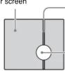
A "smear" may appear to extend vertically from very bright subjects, as shown below.
Video monitor screen
Pale vertical smear
Very bright subject (such as an electric lamp, fluorescent lamp, sunlight, or strong reflected light)
This phenomenon is common to CCD imaging elements using an interline transfer system, and is caused when electric charge induced by infrared radiation deep within the photo sensor is transferred to the resistors.
Aliasing
When shooting fine stripes, straight lines or similar patterns, the lines may become slightly jagged.
Blemishes
A CCD image sensor consists of an array of individual picture elements (pixels). A malfunctioning sensor element will show up as a single pixel blemish in the image. This is generally not a problem.
White speckles
When you shoot a poorly illuminated object at a high temperature, small white dots may appear all over the entire screen image.
About the Supplied Manuals
Names of Manuals
The following manuals are supplied with this unit.
Installation Manual (this document)
The Installation Manual describes the names and functions of the parts of the camera, the installation and connections of the camera, etc. Be sure to read it before operating the camera.
User's Guide (stored in the CD-ROM)
The User's Guide describes the setup of the camera and the operations from the Web browser.
To open the User's Guide, see "Using the CD-ROM Manuals" below
Using the CD-ROM Manuals
The supplied CD-ROM disc includes the User's Guides for this unit (Japanese, English, French, German, Spanish, Italian and Chinese versions) in PDF format.
Preparations
The Adobe Reader Version 6.0 or higher must be installed on your computer in order to use the User's Guide stored in the CD-ROM disc.
Note
If Adobe Reader is not installed, it may be downloaded from the following URL: http://www.adobe.com/
Reading the manual in the CD-ROM
1 Insert the CD-ROM in your CD-ROM drive.
A cover page appears automatically in your Web browser.
If it does not appear automatically in the Web browser, double-click on the index.htm file on the CD-ROM.
2 Select and click on the manual that you want to read.
This opens the PDF file of the manual.
Clicking an item in the Table of Contents allows you jump to the relevant
Notes
- The files may not be displayed properly, depending on the version of
Adobe Reader. In this case, install the latest version, which you can download from the URL mentioned in "Preparations" above.
you have lost or damaged the CD-ROM, you can purchase
replacement. Contact your Sony service representative.
Adobe, Acrobat and Acrobat Reader are trademarks of Adobe Systems Incorporated in the United States and/or other countries.
Location and Function of Part
The figure shows the camera without the dome casing and the slit cover.
Side
①Indoor wiring slit (knockout type)
When you wire indoors, cut this part with a nipper or similar and feed the cable through it.
Note
Take care not to trap the cable between the camera and the ceiling or the wall. If the cable is trapped, it may cause a fire or electric shock due to breaking.
②Camera head holder
③Lens
④ Lens ring fixing screw
Loosen this screw before adjusting the zoom and focus, then tighten it to fix the lens position. The screw can be inserted at one of three points.
⑤Zoom ring
Turn this ring to adjust the field of view.
⑥ Focus ring
Turn this ring to adjust the focus.
Inside
⑦Dome casing screw hole
⑧ LAN indicator (green)
This indicator flashes in green when the camera is connected to the network. The indicator goes off when the camera is not connected to the network.
9 POWER indicator (green)
When the power is supplied to the camera, the camera starts checking the system. If the system is normal, this indicator lights up.
⑩ Reset switch
To reset the camera to the factory default settings, hold down this switch with a point and supply the power to the camera.
⑪Camera installation hole (2 positions)
⑫Camera head fixing screw
First loose the screw and face the camera head to the desired direction, then tighten the screw to fix it.
⑬MONITOR output jack
Connect to a video input connector of a monitor. You can adjust the camera while looking at the image on the monitor. After adjusting the camera, disconnect the cable.
Bottom
⑭LAN port (RJ45)
Connect to a hub or computer on the 10BASE-T or 100BASE-TX network using a network cable (UTP, category 5).
⑮I/O (Input/Output) port
This port is provided with a sensor input and two alarm outputs. Pin assignment of I/O port

| Pin No. | Pin name |
| 1 | Sensor In + |
| 2 | Sensor In – (GND) |
| 3 | Alarm Out 1 + |
| 4 | Alarm Out 1 – |
| 5 | Alarm Out 2 + |
| 6 | Alarm Out 2 – |
For details on each function and required settings, see the User's Guide stored in the supplied CD-ROM. For wiring, see "Connecting the I/O port".
1612V DC/ 24V AC (power input) connector
Connect to a 12V DC or 24V AC power supply system with the supplied AC power cord.
⑰ (line output) jack (minijack, monaural)
Connect a commercially available speaker system with the built-in amplifier.
18 (microphone input) jack (minijack, monaural)
Connect a commercially available microphone.
19 (video output) connector (BNC type)
Outputs a composite video signal. Connect to a composite video input connector of a video monitor, VCR, etc. Use the supplied monitor cable for connection.
⑳Screw hole for wire rope
Monitoring the Camera Image
Install and connect the camera properly following the instructions in this manual, then operate the camera referring to the User's Guide contained in the supplied CD-ROM.
(continued on the reverse side)
[Non-Text]
[Non-Text]
A
[Non-Text]
[Non-Text]
[Non-Text]
[Non-Text]
[Non-Text]
[Non-Text]
[Non-Text]
[Non-Text]
[Non-Text]
[Non-Text]
[Non-Text]
[Non-Text]
[Non-Text]
[Non-Text]
[Non-Text]
B
[Non-Text]
[Non-Text]
[Non-Text]
[Non-Text]
[Non-Text]
[Non-Text]
[Non-Text]
[Non-Text]
[Non-Text]
[Non-Text]
[Non-Text]
[Non-Text]
[Non-Text]
[Non-Text]
[Non-Text]
[Non-Text]
[Non-Text]
[Non-Text]
A

B

C

D

E

F

G

H

1

J

K
L

M
1

2
N
Bottom
2 - ∅5 (7/32) hole

Side

Unit: mm (inches)
Installation
Before Installation
After deciding the direction in which the camera will shoot, make the required hole ( 40 to 60 mm ( 15/8 to 23/8 inches)) for the connecting cables using the supplied template. Then decide the two mounting hole positions to install the camera. (D)
Mounting screws
The camera is provided with two 5 mm ( 7/32 inch) mounting holes. Install the camera on a ceiling or wall with screws.
The required mounting screws differ depending on the installation location and its material. (Mounting screws are not supplied.)
Steel wall or ceiling: Use M4 bolts and nuts.
Wood wall or ceiling: Use M4 tapping screws. The panel thickness must be 15 mm (\% inch) or more.
Concrete wall: Use appropriate anchors, bolts and plugs for concrete walls Junction box: Use screws to match the holes on the junction box.
WARNING
The required mounting screws differ depending on the installation location and its material. If you do not secure the camera with the appropriate mounting screws, the camera may fall off.
Installing the Camera
1
① Pull out the screw cover and loosen the screw with a Phillips screwdriver.
② Turn the dome casing to the curved mark position on the camera unit, and remove the dome casing from the camera unit. When the screw is caught on the screw hole, pull up the screw.
2 Remove the slit cover.
Remove it expanding the slit cover. (F)
3 When installing on a ceiling or wall, fix the supplied wire rope to the bottom of the camera and the ceiling (or wall). (C)
① Fix the wire rope with the supplied shoulder screw to the hole for the wire rope on the bottom of the camera.
4 Install the camera on the ceiling or wall with the two screws. (G)
WARNING
- If you want to install the camera at a height such as on a ceiling, entrust the installation to an experienced contractor or installer.
- If you install the camera at a height, ensure that the installation location and its material are strong enough to withstand a weight of 10 kg (22 lb 1 oz) or more, and then install the camera securely. If they are not strong enough, the camera may fall and cause serious injury.
• To prevent the camera from falling, be sure to attach the supplied wire rope.
- If you install the camera at a height, check periodically, at least once a year, to ensure that the connection has not loosened. If conditions warrant, perform this periodic check more frequently.
Note
If you cannot use screws on a ceiling or wall, or if you want to hide the camera to be less conspicuous, use the YT-ICB45 in-ceiling bracket (optional) with which you can mount the camera on the ceiling.
Adjusting the Camera Direction and Coverage
1 Loosen the camera head fixing screw.
2 Adjust the camera to turn the lens in the desired direction.
3 Tighten the camera head fixing screw to fix the camera.
4 Loosen the lens ring fixing screw
5 Turn the zoom ring to adjust the angle of view.
6 Turn the focus ring to adjust the focus.
7 Tighten the lens ring fixing screw to fix the zoom and the focus.
8 Repeat steps 1 to 7 until the coverage and the focus are determined.
Notes
- When you adjust the camera head angle without loosening camera head fixing screw, an internal metallic part may be damaged.
- If the camera head is too heavy to be adjusted, loosen the camera head fixing screw until it moves freely.
- When the lens is not put in the slit of the camera head holder, the
moving range of the camera head is limited.
- Do not turn the lens more than 360 degrees. As this may damage the wiring inside.
- There are three screw holes for fixing the lens ring at 120 degree intervals. If the lens ring fixing screw poses a problem for adjusting the camera direction and coverage due to the direction of the camera head, detach the screw and reattach it to another screw hole, then adjust the camera direction and coverage again.
- When adjusting the angle, be sure that the TOP mark on the camera head section faces the ceiling. If the camera is installed with the TOP mark facing the floor, the image appears upside down.
Attaching the Dome Casing
1 Attach the slit cover. (I)
Notes
- The proper position of the slit cover is slightly apart from the camera mount. Do not push in by force.
- If you cannot attach the slit cover because the barrier of the lens ring fixing screw prevents it, attach the lens ring fixing screw to another screw hole. There are three screw holes for the lens ring fixing screw on the concentric circle.
2 Fix the dome casing and the camera unit. (J)
① Align the carved mark on the dome casing with that on the camera unit, and turn the dome casing in the direction of the arrow. ② Secure the screw and put the screw cover.
Connection
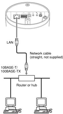
Connecting this unit to a local network
Using a commercially available network cable (straight), connect the LAN port of this unit to a hub in the network.
Connecting this unit to a computer
Using a commercially available network cable (cross), connect the LAN port of this unit to the network connector of a computer.
Connecting the power source
There are three ways to supply the power source to this product, as follows.
• 12 V DC
• 24 V AC
- Power supply equipment pursuant to IEEE802.3af (PoE* system) *PoE means Power over Ethernet.
Note
If the power is supplied from the power input terminal and LAN port at the same time, the power from the LAN port has priority over the other.
Connecting to 12 V DC or 24 V AC source (L)
Connect the AC power cord to the 12 V DC/24 V AC connector on the rear and a 12 V DC or 24 V AC source.
- Use a 12 V DC or 24 V AC source isolated from 100 to 240 V AC. Each usable voltage ranges are as follows.
12 V DC: 10.8 V to 13.2 V
24 V AC: 21.6 V to 26.4 V
- Use UL cable (VW-1 style 1007) for these connections.
Connecting to the power supply equipment pursuant to IEEE802.3af
The power supply equipment pursuant to IEEE802.3af supplies the power through a LAN port. For details, refer to the Instruction Manual of the equipment.
Connecting the I/O port M
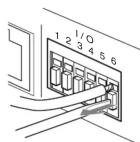
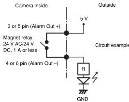
While holding down the button on the slot to which you want to connect the wire (AWG No. 28 to 22) with a small slotted screwdriver, insert the wire into the slot. Then release the screwdriver from the button. Repeat this procedure to connect all required wires.
Wiring diagram for sensor input
Mechanical switch/open collector output device

Wiring diagram for alarm output
Specifications
Network
Protocol TCP/IP, ARP, ICMP, HTTP, FTP (server/
client), SMTP (client), DHCP (client), DNS (client), NTP (client), SNMP (MIB-2), RTP/BTCP
Compression
Video compression format JPEG/MPEG4/H.264
Audio compression format G./11/G./26 (40,32,24,16 kbps)
640 × 480 (VGA), 320 × 240 (QVGA),
160 × 120 (QQVGA)
Maximum frame rate SNC-DF50N: 30 fps
SNC-DF50P: 25 fps
Web browser Internet Explorer Ver. 6.0 (Available OS)
Computer environments CPU: Pentium 4, 1.5 GHz or higher
(Pentium 4.2.4 GHz or higher
recommended)
RAM: 256 MB or more
Display size: 1024 × 768
Maximum user access 20 users
sic authentication), IP
filtering
Homepage customization Starting from a homepage in the built-in
flash memory possible.
Other functions Detection, image trimming, built-in clock
etc.
Camera
Signal system SNC-DF50N: NTSC color system
SNC-DF50P: PAL color system
Image device 1/3 type interline transfer CCD
tal picture elements
SNC-DF50N: Approx. 410,000
SNC-DF50P: Approx. 4
Effective picture elements
SNC-DF50N: Approx. 380,000
SNC-DF50P: Approx. 440,000
Synchronization Internal synchronization
Horizontal resolution 480 TV line (analog video)
Video S/N 50 dB (AGC OFF)
0.7 lx (F1.3)
ON/OFF
Shutter speed Manual
SNC-DF50N: 1/60-1/10000 sec
SNC-DF50P: 1/50-1/10000 sec.
White balance
Lens (standard equipment)
Focal length 2.8 to 10 mm
Maximum relative aperture F1.3
View angle Vertical 73.9° to 20.8°
Horizontal 100.8 to 27.7 Minimum chest distance 300 mm
Minimal: object distance = 0.5 mm
Interface
LAN port TOBASE-T/100BASE-TX, auto negotiation (RJ-15)
I/O port
Sensor input: x 1, make contact, break
contact
Alarm output: × 2, 24 V AC/DC, 1 A
(mechanical relay outputs electrically
isolated from the camera)
Video output
VIDEO OUT: BNC, 1.0 Vp-p, 75 ohms,
Microphone input
Minjiack (monaural)
Plug-in-power supported (rated voltage:
2.5 V DC)
Recommended load impedance 2.2
Line output
Minijack (monaural), Maximum output
level: 1 Vrms
Others
Power supply
12 V DC ±10%
24 V AC ± 10%, 50/60 Hz
[Non-Text]
PoE
Power consumption
9 w max.
Operating temperature
-10 °C to +50 °C (14 °F to 122 °F)
Storage temperature
-20 ℃ to +60 ℃ (→ F to +140 ℃)
Operating humidity Storage humidity
20 to 60 %
Storage Humidity Dimensions (diar
(1) (N)
2.1.1.1.1.1 (shares
126 × 140.5 mm (5 × 5 5 /a inches)
[Non-Text]
not including the projecting parts
Mass
Approx. 920 g (2 lb), not including cables
Supplied accessories
CD-ROM (User's Guide and supplied
[Non-Text]
programs) (1), Template (1),
Wire rope (1), Shoulder screw M4 (1)
AC power cord (1), Monitor cable (1),
Installation Manual (1)
Optional accessory
In-ceiling bracket YT-ICB45
Design and specifications are subject to change without notice
Always verify that the unit is operating properly before use. SONY WILL NOT BE LIABLE FOR DAMAGES OF ANY KIND INCLUDING, BUT NOT LIMITED TO, COMPENSATION OR REIMBURSEMENT ON ACCOUNT OF THE LOSS OF PRESENT OR PROSPECTIVE PROFITS DUE TO FAILURE OF THIS UNIT, EITHER DURING THE WARRANTY PERIOD OR AFTER EXPIRATION OF THE WARRANTY, OR FOR ANY OTHER REASON WHATSOEVER.
Regular parts replacement
Some of the parts that make up this product (electrolytic condenser, for example) need replacing regularly depending on their life expectancies. The lives of parts differ according to the environment or condition in which this product is used and the length of time it is used, so we recommend regular checks. Consult the dealer from whom you bought it for details.


- IPELA DynaView
- SNC-DF50N/DF50P
- Owner's Record
- WARNING
- WARNING (for Installers only)
- CAUTION
- CAUTION for LAN port
- Power Supply
- Caution for U.S.A. and Canada
- Caution for other countries
- For customers in the U.S.A. (SNC-DF50N only)
- For Customers in Canada (SNC-DF50N only)
- For customers in other countries
- ATTENTION
- Features
- Notes on Use
- Operating or storage location
- Ventilation
- Transportation
- Cleaning
- Note on laser beams
- Typical CCD Phenomena
- Vertical smear
- Aliasing
- Blemishes
- White speckles
- About the Supplied Manuals
- Names of Manuals
- User's Guide (stored in the CD-ROM)
- Using the CD-ROM Manuals
- Preparations
- Note
- Reading the manual in the CD-ROM
- Notes
- Location and Function of Part
- Side
- ①Indoor wiring slit (knockout type)
- ②Camera head holder
- ③Lens
- ④ Lens ring fixing screw
- ⑤Zoom ring
- ⑥ Focus ring
- Inside
- ⑦Dome casing screw hole
- ⑧ LAN indicator (green)
- POWER indicator (green)
- ⑩ Reset switch
- ⑪Camera installation hole (2 positions)
- ⑫Camera head fixing screw
- ⑬MONITOR output jack
- Bottom
- ⑭LAN port (RJ45)
- ⑮I/O (Input/Output) port
- 1612V DC/ 24V AC (power input) connector
- ⑰ (line output) jack (minijack, monaural)
- (microphone input) jack (minijack, monaural)
- (video output) connector (BNC type)
- ⑳Screw hole for wire rope
- Monitoring the Camera Image
- [Non-Text]
- A
- B
- C
- Installation
- Before Installation
- Mounting screws
- Installing the Camera
- Adjusting the Camera Direction and Coverage
- Attaching the Dome Casing
- Attach the slit cover. (I)
- Connection
- Connecting this unit to a local network
- Connecting this unit to a computer
- Connecting the power source
- Connecting to 12 V DC or 24 V AC source (L)
- Connecting to the power supply equipment pursuant to IEEE802.3af
- Connecting the I/O port M
- Wiring diagram for sensor input
- Specifications
- Network
- Compression
- Camera
- White balance
- Lens (standard equipment)
- Interface
- Others
- Optional accessory
- Regular parts replacement
Brand : SONY
Model : SNC-DF50N
Category : Security Camera