
SRG-X400UH - Security Camera SONY - Free user manual and instructions
Find the device manual for free SRG-X400UH SONY in PDF.


| Product Type | PTZ Security Camera |
| Image Sensor | 1/2.5-type Exmor R CMOS |
| Effective Pixels | Approx. 8.5 Megapixels |
| Lens | Integrated 20x optical zoom lens |
| Optical Zoom | 20x |
| Horizontal Viewing Angle | Approx. 61.5° (wide) to 3.2° (tele) |
| Minimum Illumination | 1.6 lux (50 IRE, F2.0, 1/30s, High Sensitivity Off) |
| Video Output | 3G-SDI, HDMI, IP (Streaming) |
| Control Interface | RS-422, RJ-45 (IP), VISCA |
| Power Supply | DC 19.5V (AC adapter included) or PoE+ (IEEE 802.3at) |
| Power Consumption | Approx. 20W (max) |
| Dimensions (W x H x D) | Approx. 170 x 181 x 190 mm (without protrusions) |
| Weight | Approx. 1.7 kg (without mount) |
| Operating Temperature | 0°C to 40°C (32°F to 104°F) |
| Storage Temperature | -20°C to 60°C (-4°F to 140°F) |
| Mount Type | Desktop or ceiling mount (bracket sold separately) |
| Functions | PTZ (Pan/Tilt/Zoom), Auto Tracking, Preset Positions, Image Flip |
| Maintenance | Clean the exterior with a soft dry cloth. Do not use solvents or abrasive cleaners. |
| Safety | Use only the specified power adapter. Avoid exposure to rain or moisture. Do not disassemble. |
| Spare Parts | AC adapter (AC-UES1230), remote commander, mounting bracket (optional) |
| Repairability | Contact Sony authorized service center for repairs. No user-serviceable parts inside. |
| General Info | Manufacturer: Sony; Model: SRG-X400UH |
Frequently Asked Questions - SRG-X400UH SONY
User questions about SRG-X400UH SONY
0 question about this device. Answer the ones you know or ask your own.
Ask a new question about this device
Download the instructions for your Security Camera in PDF format for free! Find your manual SRG-X400UH - SONY and take your electronic device back in hand. On this page are published all the documents necessary for the use of your device. SRG-X400UH by SONY.
USER MANUAL SRG-X400UH SONY
Operating Instructions
Software Version 3.00
Before operating the unit, please read this manual thoroughly and retain it for future reference.
BRC-X400/X401
SRG-X400/X402/201M2
SRG-X120/HD1M2
Table of Contents
Overview
Using This Manual ....5
Precautions for Preventing Access to the
Camera by an Unintended Third Party ...... 6
Features 6
Location and Function of Parts
Camera 8
Infrared Remote Commander (supplied) ....11
System Configuration
Operating a Single Camera Using the
Supplied Remote Commander 13
Operating a Single Camera Using the
Optional Remote Controller 14
Operating Multiple Cameras Using the
Optional Remote Controller 15
Installation and Connection
Installing the Camera 16
Installing the camera on a desk 16
Attaching the Camera to a Tripod ..... 16
Installing the Camera Using the M3 Fixing
Screw Holes 16
Installing the camera on the ceiling ..... 16
Connecting the Camera 19
Connecting to an AC power supply ..... 19
Connecting the camera to a PoE+ (Power over Ethernet Plus) power supply device 20
Connecting a single camera to a switcher, recorder, or monitor 21
Connecting a single camera to a single remote controller (not supplied) ...... 21
Connecting multiple cameras to a single remote controller (not supplied) .....22
Connecting a commercially available video switcher 23
External synchronization (BRC-X400/X401) 24
Connecting to commercially-available microphones etc. 25
Operations Using the Supplied Infrared Remote Commander
Before Starting Operations 26
Turning on the Power 26
Operating Multiple Cameras Using the
Infrared Remote Commander 26
Pan/Tilt Operation 27
Zoom Operation 28
Adjusting the Camera 28
Focusing on a subject 28
Shooting with back lighting 28
Storing the Camera Settings in Memory-
Preset Feature 29
Storing the camera status 29
Recalling the stored status 29
Clearing the preset memory 29
Storing Camera Pan/Tilt and Zoom Operations
- PTZ TRACE function (BRC-X400/X401) .... 30
Recording pan/tilt and zoom operations 30
Playing pan/tilt and zoom operations 30
Deleting recorded pan/tilt and zoom operations 30
Operating Menus 31
Displaying a menu 31
Returning to the main menu ....31
Canceling a menu 31
Adjusting and Configuring the Camera through On-Screen Menus
About On-Screen Menus 32
Confirming selection of menu items and settings/Executing operations .... 32
Main menu 32
Setting menu 33
Status 33
EXPOSURE Menu 33
COLOR Menu 35
DETAIL Menu 37
KNEE Menu (BRC-X400/X401) 38
GAMMA/VISIBILITY ENHANCER Menu (BRC-
X400/X401) 38
GAMMA 38
VISIBILITY ENHANCER 39
VISIBILITY ENHANCER Menu (SRG-X400/
FOCUS Menu (SRG-X120/HD1M2) .....41
PICTURE/OPTICAL FILTER Menu ....41
PICTURE 41
OPTICAL FILTER 42
PAN TILT/PRESET RECALL Menu ....43
PAN TILT 43
PRESET RECALL 44
PICTURE PROFILE Menu (BRC-X400/X401) 44
VIDEO OUT Menu 45
HDMI 45
H PHASE (BRC-X400/X401) 45
SYSTEM Menu 46
PTZ TRACE Menu (BRC-X400/X401) .....47
Recording pan/tilt and zoom operations 48
Playing pan/tilt and zoom operations 48
Deleting recorded pan/tilt and zoom operations 48
STATUS Menu 49
DEVICE INFO (Device information of the camera and setting status of switches on the back of the camera) 49
NETWORK 50
Menu Configuration 51
Accessing the Camera from a Web Browser
Enabling HTTP/RTSP in the Camera .....57
Setting-up the Computer ....57
OS/Web browser 57
CPU 57
Memory 57
Display 57
Accessing the Camera from a Web Browser 58
Changing the Initial Password 58
Displaying the Viewer Screen Properly ..... 58
When You Use Antivirus Software on Your Computer 58
When the SSL Function is Used ....59
Operating the Camera from a Web Browser
About Authentication 60
Operating the Camera 60
Main Menu 60
Control Panel Section 61
Monitor Screen 63
Configuring the Camera from a Web Browser
Basic Operations of the Administrator Menu 64
How to set up the Administrator menu 64
Common buttons in each menu .....64
Notes for all aspects of the menu ..... 64
Configuration of the Administrator Menu 65
System menu 65
Video menu 65
Audio menu 65
Network menu 65
Security menu 65
PTZF control menu 65
Streaming menu 65
Configuring the System
— System Menu 65
Information tab 65
Date & time tab 65
Installation tab 66
Initialize tab 68
System log tab 68
Access log tab 69
Service tab 69
Option tab (SRG-X400/X402/201M2/X120/HD1M2) 69
Setting the Camera Image
— Video Menu 70
Picture tab 70
Video codec tab 74
Superimpose tab 75
Day/Night ICR tab 76
Setting the Audio
— Audio Menu ....77
Audio tab 77
Configuring the Network
— Network Menu 78
Network tab 78
QoS tab 79
UPnP tab 80
CNS tab (BRC-X400/X401) 80
Tracking data output tab (BRC-X400/X401) 80
Setting the Security
— Security Menu ....81
Administrator and User 81
User tab 82
Access limit tab 82
SSL tab (BRC-X400, SRG-X400/X120) ... 83
802.1X tab 85
System configuration of the 802.1X network ....85
Referer check tab 87
Brute force attack protection tab .....87
Setting the PTZF Control
— PTZF control Menu 88
PTZF control tab 88
Preset position tab 90
PTZ TRACE (BRC-X400/X401) 91
Setting the Streaming
— Streaming Menu ....92
Streaming tab 92
Using NDI|HX 94
Appendix
Message List 95
Camera Lamp Display 95
Camera Screen Display (Main Menu) ... 95
List of error codes for RTMP streaming 95
List of error codes for SRT streaming 96
Troubleshooting 97
Preset Items and Image Setting File Items 98
Pan/Tilt/Zoom/Focus Settings 98
Camera Settings 99
Specifications 101
Dimensions 103
SYSTEM SELECT switch settings .....104
Pin array of the VISCA RS-422 terminal and
how to use it 104
Overview
Safety Regulations (Supplied)
The important points for safe use of the camera are described.
Be sure to read the Safety Regulations.
Operating Instructions (This document/Web)
This document describes the names of the camera parts and how to install, connect, and operate the camera.
Some models on this document are not sold depending on the region.
Using This Manual
This manual is designed to be read on a computer display. The content you need to know in order to use the camera is described here. Read this manual before operation.
Jumping to a related page
When you read the instructions on a computer display, click the part displayed the relevant page to jump to the page. Relevant pages can be searched easily.
Software display examples
The software displays described in this manual are explanatory examples. Note that some displays may be different from the ones that actually appear. The menu displays and illustrations of the camera BRC-X400 are shown in the instructions as examples. Only supported functions are displayed
Printing the Operating Instructions
When you print this document, note that the displays or illustrations printed on a paper may differ from those that appear on the screen depending on your system.
About the description in this document
Resolution and frame rate are described as follows.
| 4K 3840×2160/23.98p |
| 3840×2160/25p |
| 3840×2160/29.97p |
| HD 1280×720/50p 1920×1080/50i |
| 1280×720/59.94p 1920×1080/50p |
| 1920×1080/23.98p 1920×1080/59.94i |
| 1920×1080/25p 1920×1080/59.94p |
| 1920×1080/29.97p |
In the description of HTTP/RTSP communication, RTSP communication refers to the IP streaming function.
This manual or the software described herein, in whole or in part, may not be reproduced, translated or reduced to any machine readable form without prior written approval from Sony Corporation © 2019 Sony Corporation
SONY CORPORATION PROVIDES NO WARRANTY WITH REGARD TO THIS MANUAL, THE SOFTWARE OR OTHER INFORMATION CONTAINED HEREIN AND HEREBY EXPRESSLY DISCLAIMS ANY IMPLIED WARRANTIES OF MERCHANTABILITY OR FITNESS FOR ANY PARTICULAR PURPOSE WITH REGARD TO THIS MANUAL, THE SOFTWARE OR SUCH OTHER INFORMATION. IN NO EVENT SHALL SONY CORPORATION BE LIABLE FOR ANY INCIDENTAL, CONSEQUENTIAL OR SPECIAL DAMAGES, WHETHER BASED ON TORT, CONTRACT, OR OTHERWISE, ARISING OUT OF OR IN CONNECTION WITH THIS MANUAL, THE SOFTWARE OR OTHER INFORMATION CONTAINED HEREIN OR THE USE THEREOF.
Sony Corporation reserves the right to make any modification to this manual or the information contained herein at any time without notice. The software described herein may also be governed by the terms of a separate user license agreement.
• is trademark of Sony Corporation.
• HDademark of Sony Corporation.
- "Exmor R" and Exmor R TM are trademarks of Sony Corporation.
- The terms HDMI and HDMI High-Definition Multimedia Interface, and the HDMI Logo are trademarks or registered trademarks of HDMI Licensing Administrator, Inc. in the United States and other countries.
- Microsoft, Windows, and Internet Explorer are registered trademarks of United States Microsoft Corporation in the United States and/or other countries.
- JavaScript is a trademark or registered trademark of Oracle Corporation, its affiliates or subsidiaries in the United States and other countries.
- NewTek™ and NDI® are registered trademarks of NewTek, Inc.
• macOS is a trademark of Apple Inc., registered in the U.S. and other countries.
- Google Chrome is a trademark or registered trademark of Google LLC.
- Intel, Intel logo, and Intel Core are trademarks of Intel Corporation or its subsidiaries in the United States and/or other countries.
Other system names, product names appearing in this document are trademarks or registered trademarks of their respective manufacturers. Trademarked items are not indicated by ® or TM symbols in this document.
Precautions for Preventing Access to the Camera by an Unintended Third Party
The camera settings may be changed by an unintended third party on the network, depending on the usage environment. The camera can be fraudulently accessed in a network environment where a device is connected or connectable to the network without the administrator's permission, or where a computer or other network device connected to the network can be used without any permission.
After configuring the camera, immediately change the password you use for upgrading the firmware on the camera, from a Web browser on your computer, and for changing settings. For how to change password, see "Changing the Initial Password" (page 58).
Features
Pan/Tilt/Zoom CMOS video camera equipped with a small built-in pan-tilt head
- The camera unit is equipped with a 1/2.5-type Exmor R CMOS sensor and an optical zoom lens *1 with pan/tilt/zoom features integrated into a small built-in pan-tilt head. This versatile camera can be used for various applications.
- The pan-tilt head can pan to the right or left by 170 degrees and tilt upward to 90 degrees and downward to 20 degrees, which allows the camera to remotely shoot wide areas.
- The camera pans and tilts at a speed of between 0.5 and 101 degrees (maximum speed) per second, and it also pans and tilts at a maximum speed of 300 degrees per second in the preset operation.
Zoom performance for capturing distant subjects
For BRC-X400/X401 and SRG-X402, in addition to 20 × 1 optical zoom, it uses Sony's 2 × 2 Clear Image Zoom function and 2 × Tele Convert mode *2 to achieve the equivalent of up to 80x optical telephoto performance. Moreover, using digital zoom together achieves the equivalent of up to 480x telephoto performance.
Audio output
The camera is equipped with 2ch audio which is applicable for microphone/line input. Input audio signal is transmitted to HDMI/SDI simultaneously. Additionally, the signal is transmitted to the IP network by with the streaming function.
Video output
In addition to HDMI/SDI output, IP network transmission can be performed simultaneously by IP streaming function (SDI output does not support 4K).
For IP streaming function, ITU-T H.264/H.265 is applied to video compression mode (video codec) and it achieves high compression rate while keeping the image quality. Also, it decreases the network bandwidth load.
The network bandwidth load required for video transmission decreases.
Moreover, the camera supports multi-streaming output. Up to 3 codec modes can be selected.
Preset function
Up to 100 preset data can be stored in the VISCA command and up to 256 preset data in the CGI command.
On the PTZ Motion Sync function *3 , pan, tilt, and zoom work together to enable smooth preset operations.
Equipped with RS-422 interface
The camera is equipped with RS-422 interface which is the industry standard VISCA camera protocol in external communication.
Equipped with PoE+ (Power over Ethernet Plus)
The camera supports IEEE802.3at-compatible PoE+ (Power over Ethernet Plus) and a single LAN cable is used for power supply and control.
Compatible with VISCA over IP protocol
An IP connection can be established between the camera and the remote controller.
Equipped with external video sync function (BRC-X400/X401)
The camera is equipped with an external video sync function to synchronize the camera images on multiple cameras.
Equipped with tally lamp (BRC-X400/X401)
The camera is equipped with a tally lamp that instantly distinguishes cameras in use.
Supports network connection with RCP/MSU (BRC-X400/X401)
Network connection to an optional remote control panel (RCP) or master setup unit (MSU) is supported.
Picture profile preset function (BRC-X400/X401)
Picture profile presets from PP1 to PP6 can be loaded. By using these presets, an image texture gets close to the one shot with other cameras with the picture profile function, and the camera creates an image texture similar to the one of cinematic film.
Extensibility
4K Option (SRGL-4K)
SRG-X400/X402/201M2/X120/HD1M2 (HD model) supports 4K video output via HDMI and 4K IP streaming by installing the optional 4K Option license. (page 69) 3
NDI|HX
This camera is compatible with NDI|HX of NewTek, Inc.
To use NDI|HX, you are required to purchase the license key (page 94).
*1 20× optical zoom for the BRC-X400/X401 and SRG-X400/X402/201M2
12× optical zoom for the SRG-X120/HD1M2
*2 When shooting at 1920×1080 only.
*3 Enabled by Software version 2.00
Location and Function of Parts
Camera
Front

1 Tally lamp (BRC-X400/X401)
Lights up in red when a tally command is received or the camera is selected by an optional remote controller (depending on the setting mode). The brightness can be selected from [HIGH], [LOW], or [OFF] (the tally lamp does not light up) in [TALLY LEVEL] in the SYSTEM menu.
2 Lens
This is a 20× (BRC-X400/X401, SRG-X400/X402/201M2) or 12× (SRG-X120/HD1M2) magnification-optical zoom lens. When [CLEAR IMAGE ZOOM] (Clear Image Zoom) is set to [ON] in the PAN TILT ZOOM menu, the camera can zoom up to 30× for 4K and 40× for HD. CLEAR IMAGE ZOOM is not available for SRG-X120/HD1M2.
Note
Do not touch the part around the lens when energized.
3 Remote commander sensors
These are sensors for the supplied remote commander.
4 POWER lamp
Flashes in green when the camera is connected to an outlet using the supplied AC adapter and power cord, or when power is being supplied by connecting the camera
and PoE+ power supply device with a LAN cable. The green lamp stops flashing and lights up when start-up is complete.
The green lamp flashes when the camera receives an operation command from the supplied remote commander.
The lamp lights up in orange when the POWER button on the supplied remote commander is pressed and the camera enters in the standby mode.
The yellow lamp flashes while upgrading the firm ware.
The orange lamp flashes when there are defects in the camera (for instance, when rotations of fan motor slow down or stop etc.).
5 NETWORK lamp
Flashes during initialization when the camera is connected to the PoE+ power supply device with a LAN cable and power is being supplied. The lamp lights up when it is connected to the network once start-up is complete.
Lights up after start-up is complete if network is connected, when power is supplied to the camera from outlet using AC adapter and power cord. The lamp is unlit when not connected to the network.
The lamp turns off while upgrading the firmware.
The lamp flashes when there are defects in the camera (for instance, when rotations of fan motor slow down or stop etc.).
Back

6 VSCA RS-422 IN terminal
Connect with an remote controller (not supplied).
When you connect multiple cameras, connect it to the VISCA RS-422 OUT terminal of the previous camera in the daisy chain connection.
7 VISCA RS-422 OUT terminal
When you connect multiple cameras, connect it to the VISCA RS-422 IN terminal of the next camera in the daisy chain connection.
8 IRSELECT switch
Select the camera number when you operate multiple cameras with the same remote commander.
9 Remote commander sensor
This is for the supplied remote commander.
10 SYSTEM SELECT switch
Used for selecting the video signal format to be output from the HDMI OUT and SDI OUT terminals. When the SYSTEM SELECT switch is set to 6, the value set on [VIDEO FORMAT] or [Format] under [Video out] on the Administrator menu is applied.
For details, see "SYSTEM SELECT switch settings" (page 104).
11 Reset switch
Press the switch for 5 seconds or longer to return to the factory default.
12 (earth) terminal
13 AC adapter cord clamper
Fix the cord of an AC adapter with the cord clamper so that it does not come out.
14 MIC terminal (audio input terminal)
Input for commercially-available MIC or LINE to connect an audio device.
* Switch between MIC and LINE input, as indicated on "Connecting to commercially-available microphones etc." (page 25).
15 CAMERA SETUP switches
Perform settings for the following 4 cameras.
CAMERA SETUP switch settings

| Switch No. Setting items | |
| 1 Setting up 3G-SDI level | |
| 2 Termination setting of external synchronization | |
| 3 HTTP/RTSP communication usage setting | |
| 4 Baud Rate settings of RS-422 for VISCA communication |
① SDI format/level settings
This setting is enabled when the signal format is 1920 × 1080/50p or 1920 × 1080/59.94p .
When the SYSTEM SELECT switch is set to 6, the setting set on [VIDEO FORMAT] on the OSD menu or [Format] under [Video out] on the Administrator menu is applied.
| Switch state SDI format/level | |
| ON Level-B | |
| OFF Level-A | |
* Turn the power off or to standby, then turn the power on to reflect the changes after setting.
② Termination setting of external synchronization
Use this setting during external synchronization (page 24).
When you use the external synchronization while multiple cameras are connected, turn OFF when this camera is in the middle of a daisy chain connection and turn ON when this camera is at the end.
When nothing is connected to the EXT SYNC terminal, turn ON.
| Switch state TERMINATION | |
| ON TERMINATE | |
| OFF OPEN | |
* The setting is applied instantly.
3 HTTP/RTSP communication usage setting Use this setting when you set the HTTP/RTSP protocol setting.
Turn ON to forcibly enable the setting. Turn OFF to configure the setting according to the OSD menu.
| Switch state | HTTP/RTSP CONNECTION |
| ON FORCED ON | |
| OFF MENU | |
* Turn the power off and on to reflect the changes after setting.
④ Baud Rate settings of VISCA RS-422 communication
| Switch state Baud Rate | |
| ON 38400 bps | |
| OFF 9600 bps |
* Turn the power off and on to reflect the changes after setting.
16 HDMI OUT terminal
Supplies the images as an HDMI video signal.
Note
Under the following cases, VGA output is applied to the image output through the HDMI OUT terminal and the image quality is degraded.
- When the SYSTEM SELECT switch is set to 7
- When you choose [720/59.94p VGA] for [VIDEO FORMAT] on the OSD menu
- When you choose [1280×720/59.94p (HDMI:VGA)] for [Format] on the Administrator menu
17 SDI OUT terminal
Outputs the image from the camera as an HD signal.
* Images are not output when 4K output is set.
18 EXT SYNC IN (only BRC-X400/X401)
Accepts an external sync signal.
19 LAN (network) terminal (RJ-45)
Network communication and PoE+ power supply are provided using the network cable (category 5e or higher, shielded twist pair).
For more information on the connection, refer to the instruction manual of the PoE+ power supply device.
It lights up or flashes in orange when the network is connected by 1000BASE-TX. It lights up or flashes in green when the network is connected by 100BASE-TX.
It is turned off when the network is connected by 10BASE-T or the network is disconnected. When it is turned off and the NETWORK lamp on the front of the camera is lighting up, the network is connected by 10BASE-T.
Factory settings for network
IP address: 192.168.0.100
Subnet mask: 255.255.255.0
Default gateway: 192.168.0.254
Name: CAM1
User name: admin
Password: Admin_1234
When connecting this product to a network, connect via a system that provides a protection function, such as a router or firewall. If connected without such protection, security issues may occur.
20 --- 12 V ◇C◆ (DC power input) terminal
Connect the AC adapter (supplied).
Note
Do not use any AC adapter other than the supplied AC adapter. Otherwise, a fire or malfunction may occur.
Bottom
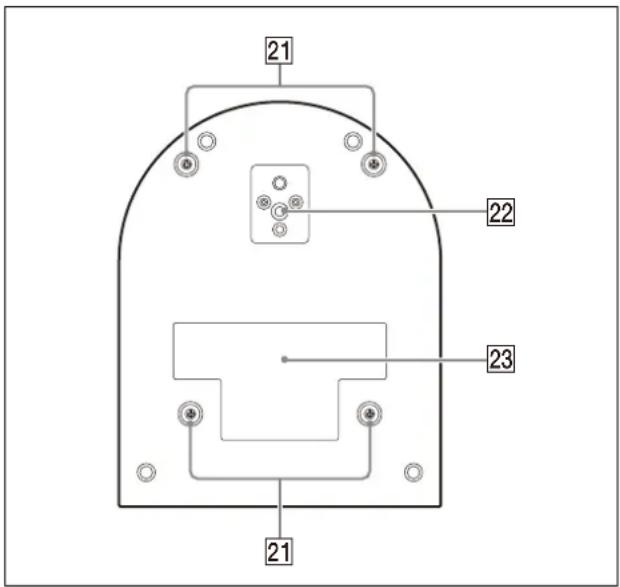
21 Ceiling bracket mounting screw holes
When installing on the ceiling, use the screw holes to attach the supplied ceiling bracket (A). For details, see "Installing the Camera" (page 16).
22 Tipod socket hole
Use this to attach the tripod, etc.
For details, see "Attaching the Camera to a Tripod" (page 16).
23 Rating label
This label shows the name of device and its electric rating.
Important
The product name and electric rating are located at the bottom of the unit.
Infrared Remote Commander (supplied)

1 CAMERA SELECT buttons
Press the button corresponding to the camera you want to operate with the remote commander. The camera number can be set using the IR SELECT switch on the back of the camera.
Note
If two or more cameras are adjacent and have the same camera number, they are operated simultaneously with the supplied remote commander. When you install the cameras close to each other, set different camera numbers.
For setting of camera number, see "Operating Multiple Cameras Using the Infrared Remote Commander" (page 26).
2 FOCUS buttons
Used for focus adjustment.
Press the AUTO button to adjust the focus automatically. To adjust the focus manually, press the MANUAL button, and adjust it with the FAR and NEAR buttons.
Note
Press the MANUAL button and adjust the focus manually when shooting the following objects.
- White walls and other objects without contrast
- Objects behind glass
- Objects with horizontal stripes
- Objects on which bright lights are cast or reflected
• Nightscapes and other dark objects with blinking lights - Lit objects shot with darkened exposure adjustment or exposure compensation settings
3 DATA SCREEN button
Press this button to display the main menu PAGE. Press it again to close the menu. If you press the button when a lower-level menu is selected, the display goes back to a higher-level menu.
Notes
- You cannot perform pan/tilt/zoom operations while the menu is displayed.
- The menu is not displayed on the SDI output image when the [Menu overlay (SDI)] check box on the Administrator menu is not selected.
- The menu is not displayed on the HDMI output image when the [Menu overlay (HDMI)] check box on the Administrator menu is not selected.
4 PAN-TILT button
Press the arrow buttons to pan or tilt the camera. Press the HOME button to face the camera back to the front.
When the menu is displayed, use ↑ or ↓ to select the menu items and ← or → to change the set values.
The selected setting menu is displayed by pressing the HOME button when the main menu is displayed.
5 VR DIRECTION SET button
Hold down this button and press the REV button to change the direction of the camera movement to be opposite the direction of the arrows on the ⇔ and ⇒ buttons. To reset the direction of the camera movement, press the STD button while holding down this button.
6 POWER button
Press this button to turn on power or to put the camera in the standby mode.
7 BACK LIGHT button
Press this button to enable backlight compensation. Press it again to disable backlight compensation.
Note
The BACK LIGHT button is enabled when MODE (Exposure mode) on the EXPOSURE menu is set to [FULL AUTO] (Full auto), [SHUTTER Pri] (Shutter priority), or [IRIS Pri] (Iris priority).
8 POSITION buttons
Hold down the PRESET button and press button 1 to 6 to store the current camera direction, zoom, focus adjustment and backlight compensation in the memory of the pressed number button. To erase the memory contents, hold down the RESET button and press button 1 to 6.
Notes
• These buttons do not function when the menu is displayed.
- Some memory contents may not be erased even if you use the RESET button.
For details on items that can be stored by the PRESET button and erased by the RESET button, see "Preset Items and Image Setting File Items" (page 98).
9 AN-TILT RESET button
Press this button to reset the pan/tilt position.
10 ZOOM buttons
Use the SLOW button to zoom slowly, and the FAST button to zoom quickly. Press the T (telephoto) side of the button to zoom in, and the W (wide angle) side to zoom out.
Installing batteries in the remote commander

Required batteries
Two R6 (size AA) batteries are required for the remote commander. To avoid the risk of explosion, use R6 (size AA) manganese or alkaline batteries.
Note
Danger of explosion if the batteries are incorrectly replaced. Replace only with the same or equivalent type recommended by the manufacturer. When you dispose of the batteries, you must obey the laws of your area or country.
R6 (size AA) batteries are not supplied.
System Configuration
This camera can be arranged into various system configurations with other products (not supplied). This section describes typical system examples, with the required components and the main usage of each system.
Operating a Single Camera Using the Supplied Remote Commander
What you can do with this system
Operate the camera readily from a short distance.
System Configuration
![graph LR A["Remote commander (supplied)"] --> B["Video monitor"] C["Video signal"] --> B D["Signal flow"] --> B](/content/2026/05/1130412/images/bf6043f39c87bcf0ac6283b826ed39810fc4dc9003ede878f282b5889561a177.jpg)
Operating a Single Camera Using the Optional Remote Controller
What you can do with this system
Perform pan/tilt and zoom operations using the joystick of the remote controller.
System Configuration
![graph TD A["Radio System"] --> B["Video monitor"] B --> C["Remote controller"] C --> D["Signal flow"] style A fill:#f9f,stroke:#333 style B fill:#ccf,stroke:#333 style C fill:#cfc,stroke:#333 style D fill:#fcc,stroke:#333](/content/2026/05/1130412/images/c93f7fe198a87741e7bd34d71b2f57517911c97f92ee6dd6fb8b44d840a2bada.jpg)
Operating Multiple Cameras Using the Optional Remote Controller
What you can do with this system
- For the RS-422 connection, you can remotely operate up to seven cameras with a single remote controller.
- Perform pan/tilt and zoom operations using the joystick.
System Configuration
![graph TD A["Device 1"] -->|Video signal| B["Video monitor"] C["Device 2"] -->|Remote Control (VISCA) signal| B D["Device 3"] -->|Tally/contact signal| B B --> E["Video switcher"] E --> F["Remote controller"] F --> G["Signal flow"] style A fill:#f9f,stroke:#333 style C fill:#f9f,stroke:#333 style D f…](/content/2026/05/1130412/images/e2e8e92cefb01cf2cea918368e0081a17f459880fee600376db28299df836d78.jpg)
Installation and Connection
Installing the Camera
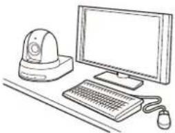
Installing the camera on a desk
Place the camera on a flat surface.
If you place the camera on an inclined surface, make sure that the inclination is less than ±15 degrees to guarantee pan/tilt performance, and take measures to prevent it from falling.
Notes
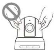
- Do not grasp the camera head when carrying the camera.
- Do not turn the camera head by hand. Doing so may result in a camera malfunction.


Attaching the Camera to a Tripod
Attach a tripod to the screw hole used for attaching a tripod on the bottom of the camera. The tripod must be set up on a flat surface and its screws tightened firmly by hand.
Use a tripod with screws of the following specifications.
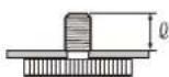
= 4.5 to 7 mm
= 0.18 to 0.27 inches
CAUTION
Installation of the camera using the tripod screws and screw holes should not be done for installation on a ceiling or a shelf, etc., in a high position.
Installing the Camera Using the M3 Fixing Screw Holes
Attach the camera using 4 M3 fixing screw holes located on the bottom of the camera.
Attach the camera to a fitting with a flat surface using M3 screws with the following specifications.

= 3 to 8 mm
= 0.12 to 0.31 inches
Installing the camera on the ceiling
Using the supplied ceiling bracket (A)/(B), wire rope, and screws, you can attach the camera to the ceiling. When you install the camera, always install it on a level ceiling. If you install it on a sloping or uneven ceiling, make sure that the place where you install it is within ±15 degrees of the horizontal.
CAUTION
- Entrust installation to an experienced contractor or installer when installing the camera on ceilings or other high locations.
- When installing the camera in a high location, be sure that the location and installation components (excluding the supplied accessories) are strong enough to support the camera and the mounting bracket, and install the camera securely. If the components are not strong enough, the camera may fall and cause serious injury.
• Always install the supplied wire rope to prevent the camera from falling. - If you install the camera in a high location, check periodically, at least once a year, to ensure that the connection has not loosened. If conditions warrant, make this periodic check more frequently.
Before installing the camera
Determine the shooting direction of the camera, and then make the holes for the ceiling bracket (B) and the connecting cables on the ceiling.
Notes
- The connecting cables cannot be passed through ceiling bracket (B). A hole for the wiring is required in the ceiling at the back of the camera where it is attached to the ceiling.
- The recommended tightening torque for each screw are described in below. M3: 0.6 N·m (6.1 kgf·cm) M2.6: 0.4 N·m (4.1 kgf·cm)
How to install the camera
1 Attach the wire rope to the ceiling.

1-2 In the case that a wire cannot be attached on the ceiling, attach the wire on the ceiling bracket (B) as illustrated below with the supplied screws (M3×8).

WARNING
Use the supplied screw. Otherwise, the wire rope may not function properly.
2 Attach the ceiling bracket (B) to the ceiling. When attaching the ceiling bracket (B) to the ceiling, it is recommended to fix at the 4 positions illustrated below. There are elongated holes for the screws along the rounded edges of the ceiling bracket (B). Later, the front of the camera will be positioned along this edge. Face the camera to the front, adjust the aim, and attach it securely.

3 Attach the ceiling bracket (A) to the bottom of the camera using the 4 screws (M 3 × 8) supplied.
Align the bracket holes with the screw holes on the camera, and attach the bracket to the camera.

Lightly tighten screws temporarily in the order indicated in the figure. Afterwards, screw each of them firmly.
CAUTION
Use the supplied screws. Otherwise, you may break the internal parts of the camera.
4 Insert the protrusions raised on the ceiling bracket (A) into the spaces prepared in the ceiling bracket (B), and temporarily attach them by pushing the ceiling bracket (A) to the rear.
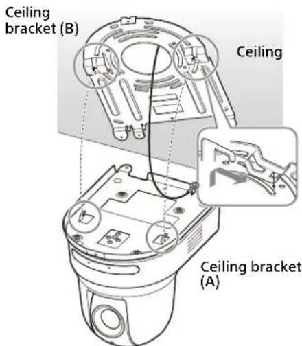
5 While pushing up the entire camera, attach it to the ceiling bracket (B) using the 3 screws (M3 × 8) supplied.

Lightly tighten screws temporarily in the order indicated in the figure. Afterwards, screw each of them firmly.
6-1 Connect the cables to the terminals at the back of the camera.

Notes
- Make sure no load is applied to the connectors of the cables.
- For measures that prevent the HDMI cable from being pulled out, proceed to "6-2" after connecting the HDMI cable. Then, connect all the other cables.
6-2 To prevent the HDMI cable from coming off, mount the HDMI cable fixing plate with the supplied screw (single, M2.6 × 6, black) on the back of the camera, then fix the HDMI cable with a banding band etc.

Note
Do not attach the HDMI cable on the camera, if you do not use it.
7 Adjust the image flip function to optimize the ceiling mounting status.
Note
All preset settings will return to their default settings when changing the setting of the image flip function. When setting, make sure to set the image flip function before the preset settings.
How to remove the camera
1 Remove the 3 screws used to attach the camera in step 5 of "How to install the camera".
2 While pushing the entire camera up towards the ceiling, move the camera to the front.
The hooks will disengage, and you can remove the camera.
Connecting the Camera
Connecting to an AC power supply
Connect the camera to an AC outlet using the supplied AC adapter and power cord.
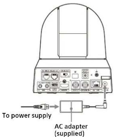
1 Connect the supplied AC adapter and power cord.

2 Fix the cord of an AC adapter with the cord clamper so that it does not come out. Unlock the cord clamper and put the cord through it.
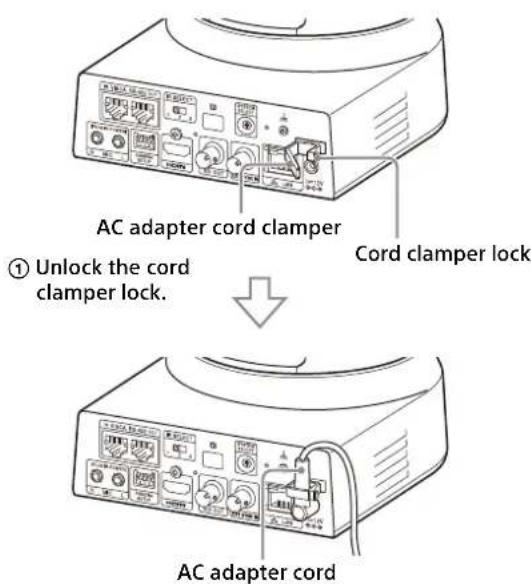
② Put the AC adapter cord through the cord clamper and lock the cord clamper.
Note
Do not use any AC adapter other than the supplied AC adapter. Otherwise, a fire or malfunction may occur.
Connecting the camera to a PoE+ (Power over Ethernet Plus) power supply device
A PoE+ (IEEE802.3at compliant) power supply device supplies power through a commercially available network cable. For details, see the operating instructions of the power supply device.
![graph TD A["Device with Internet cable"] -->|Commercially available| B["Network cable"] B --> C["Hub with PoE+ power supply feature"] D["Laptop"] --> C E["Laptop"] --> C](/content/2026/05/1130412/images/05ab0f6844d3abc5332e2c2cf491fe437bc7c529503fd04a32ff800f1faf002d.jpg)
Notes
- When you supply power from a PoE+ power source, use a network cable of Category 5e or higher.
- When both the AC adapter and PoE+ power supply are connected, power is supplied through the AC adapter.
- When power is supplied from PoE+, both the POWER lamp (green) and NETWORK lamp (green) flash until the initial verification process is complete (approximately 1 minute, depending on the power supply device).
- When the network camera is powered by a PoE+ power supply, do not route the wiring outdoors.
- If a non PoE+ compatible device is connected, both the POWER lamp (green) and NETWORK lamp (green) flash, and the camera won't start.
- When you turn the power off, wait at least 10 seconds before you turn it on again.
- Use an STP (shielded) network cable.
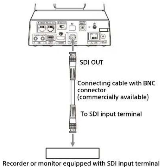
Connecting a single camera to a switcher, recorder, or monitor
Devices equipped with an HDMI input terminal

Devices equipped with an SDI input terminal (HD output):
BRC-X400/X401
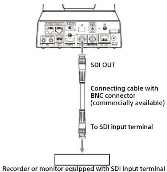
Devices equipped with an SDI input terminal (HD output):
SRG-X400/X402/201M2/X120/HD1M2
Connecting a single camera to a single remote controller (not supplied)
You cannot switch between VISCA over IP and VISCA RS-422 with the camera. Communication with the remote controller is possible by connecting a network cable. Select either VISCA over IP or VISCA RS-422 with the remote controller. For details, see the operating instructions of the remote controller.
Using VISCA over IP (LAN terminal)

Connecting a single camera to a remote controller directly
* Use a cross network cable.
Using the VISCA RS-422 terminal
A remote controller can be connected via the VISCA RS-422 terminal. The VISCA RS-422 allows connections of up to 1.2 km in length.

* Use straight network cable.
Note
When RM-IP10 is used, make a connecting cable using the camera and the RS-422 terminal board connectors supplied with the remote controller. When you make the connecting cable, refer to the pin array of the VISCA RS-422 terminal (page 104) and the VISCA RS-422 connection diagram (page 104).
Connecting multiple cameras to a single remote controller (not supplied)
You cannot switch between VISCA over IP and VISCA RS-422 with the camera. Communication with the remote controller is possible by connecting a network cable. Select either VISCA over IP or VISCA RS-422 with the remote controller. For details, see the operating instructions of the remote controller.
Using the VISCA RS-422 terminal
Up to 7 cameras can be connected via the VISCA RS-422 terminal. The VISCA RS-422 allows connections of up to 1.2 km in length.
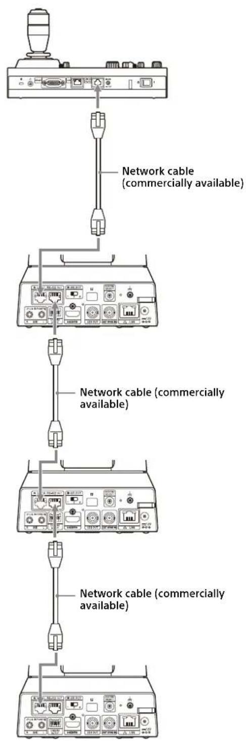
* Use straight network cables.
Note
When RM-IP10 is used, make a connecting cable using the camera and the RS-422 terminal board connectors supplied with the remote controller. When you make the connecting cable, refer to the pin array of the VISCA RS-422 terminal (page 104) and the VISCA RS-422 connection diagram (page 104).
Connecting multiple cameras using VISCA over IP
When you connect multiple cameras to a single remote controller or when you connect multiple cameras to multiple remote controllers with a computer, use a switching hub for the connection.
![graph TD A["User"] --> B["Network cable (commercially available)"] B --> C["HUB (commercially available)"] C --> D["Network cable (commercially available)"] D --> E["Device 1"] D --> F["Device 2"] D --> G["Device 3"] D --> H["Device 4"] D --> I["Device 5"] D --> J["Device 6"] D --> K["Device 7"] D -…](/content/2026/05/1130412/images/9f1e59851f7cf8e47e1be5d74b94928305b387f937ca1b3d824e9d6dfcfb3b1b.jpg)
* Use straight network cables.
Connecting a commercially available video switcher
For 4K output (HDMI output only)
When you want to switch cameras, connect a commercially available video switcher. For the connection to the video switcher, refer to the operating instructions of the switcher.
![graph TD A["TV Switcher"] --> B["Connecting control signals"] B --> C["Video switcher"] D["Commercial Cable"] --> E["Network cable (commercially available)"] E --> F["Network cable (commercially available)"] F --> G["Network cable (commercially available)"] G --> H["HDMI cable (not supplied)"] H -->…](/content/2026/05/1130412/images/9ac5671f56fe3c309df4c8684fcf9fbc9c6dd542f5b23700560b3747fff0bfab.jpg)
* Use straight network cables.
For HD output
When you want to switch cameras, connect a commercially available video switcher. For the connection to the video switcher, refer to the operating instructions of the switcher.
![graph TD A["Video monitor"] --> B["Network cable (commercially available)"] B --> C["Connecting cable with BNC connector (commercially available)"] C --> D["HDMI cable (not supplied)"] D --> E["Video switcher"] E --> F["Connecting control signals"] F --> G["Network cable (commercially available)"] G…](/content/2026/05/1130412/images/7846785e0c1757655a4675fd00275b3c0bde86c67ddf0c0728dd1ef75fa96318.jpg)
* Use straight network cables.
External synchronization (BRC-X400/X401)

For a single camera
Multiple cameras can be synchronized to a specific reference signal. Providing a reference signal to the EXT SYNC IN terminal (page 10) allows the camera to be synchronized in phase with the video signal. Depending on the video output format the compatible reference signal varies.
| Video output format Compatible reference signals | |
| 1920×1080/59.94p | 1920×1080/59.94i |
| 1920×1080/59.94i | 720×486/59.94i (NTSC) |
| 1920×1080/29.97p | |
| 1280×720/59.94p 1920×1080/59.94i | |
| 1280×720/59.94p | |
| 720×486/59.94i (NTSC) | |
| 1920×1080/50p | 1920×1080/50i |
| 1920×1080/50i | 720×576/50i (PAL) |
| 1920×1080/25p | |
| 1280×720/50p 1920×1080/50i | |
| 1280×720/50p | |
| 720×576/50i (PAL) | |
| 1920×1080/23.98p 1920×1080/47.95i (23.98PsF) | |
Notes
- When the reference signal is unstable, the camera cannot be externally synchronized.
- Sub-carriers cannot be synchronized.
- 3840×2160 cannot be synchronized.
For multiple cameras
Up to 7 cameras can be connected.
![graph TD A["Industrial Device"] -->|TERMINATION switch: ON| B["Switch"] B --> C["Commercially available Y-shaped divider"] C --> D["To SYNC OUT terminal"] A --> E["Switch"] E --> F["Commercially available Y-shaped divider"] F --> G["To SYNC OUT terminal"] style A fill:#f9f,stroke:#333 style B fill:#…](/content/2026/05/1130412/images/c94d3a2796bee5efcea81d9bc9104bead35a62978ffd6c368b546cac5abcee1d.jpg)
Note
Star connection is recommended to connect 8 cameras or more.
Connecting to commercially-available microphones etc.
Connect a commercially-available microphone, mixer, etc.
Input audio will be transmitted to the HDMI OUT and SDI OUT output and IP network streaming in stereo format.
Switch between the microphone input and line input from the Administrator menu on the web browser.
Connect a commercially-available microphone when using the microphone input.
Connect a commercially-available mixer when using the line input.

Notes
- Do not place the camera near devices that may generate noise.
- If you place a microphone near this camera, it may pick up the sound from the camera. Check the audio of the microphone input in advance when installing.
- When microphone input is selected, the camera supplies 2.5 VDC Plug-in-power. Do not connect a non-supported microphone when the microphone input is selected.
Operations Using the Supplied Infrared Remote Commander
Before Starting Operations
Before operating, check that the camera and peripheral devices are properly installed and connected.
For details, see "Installing the Camera" (page 16) and "Connecting the Camera" (page 19).
Turning on the Power

To the AC adapter (supplied)
1 Connect the camera to an AC outlet using the supplied AC adapter and power cord. Or, connect the powered PoE+ power supply device and the camera with a LAN cable.
The power is turned on and the POWER lamp turns green. The camera will automatically pan and tilt and then stop to the position stored as PRESET 1 (pan/tilt reset).
2 Turn on the peripheral devices. If the POWER button on the remote commander is pressed while the camera is turned on, the camera goes into the standby mode. The POWER lamp turns from green to orange.
Note
Wait at least 10 seconds if you want to turn on the camera again after putting it in the standby mode.
Operating Multiple Cameras Using the Infrared Remote Commander
1 Set the IR SELECT switch on the back of the camera you want to operate to 1, 2, or 3.
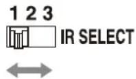
2 Press the CAMERA SELECT button on the remote commander that corresponds to the number set in step 1.

You can then operate the specified camera(s). Every time you operate the camera(s) using the remote commander, the CAMERA SELECT button pressed in step 2 lights up.
Pan/Tilt Operation

1 Press the POWER button.
The camera will turn on and perform the pan/tilt reset action automatically.
2 Press an arrow button to pan or tilt the camera.
While checking the picture on the screen, press the appropriate arrow button.
To move the camera little by little, press the button just for a moment.
To move the camera in a wide range, press and hold the button.
To move the camera diagonally, press the or button while holding down the or button.
To face the camera back to the front
Press the HOME button.
If you accidentally move the camera with your hand
Press the PAN-TILT RESET button to perform the pan/tilt reset action.
When the camera moves in a different direction from what you intended
The camera is preset to face toward the right whenever the ➤ button is pressed. You might wish to reverse the direction in which the camera moves, for example, when you change the direction of the camera while checking the picture on the screen. In such cases, press the 2 (REV) button while holding down the L/R DIRECTION SET button. To reset the setting, press the 1 (STD) button while holding down the L/R DIRECTION SET button.

Note
The above setting changes only the signal emitted from the remote commander, and does not change the setting of the camera itself. Therefore, repeat the setting process for each remote commander if you are using more than one remote commander.
If the POWER lamp and NETWORK lamp on the camera flash simultaneously, and "PAN-TILT ERROR!" is displayed on the menu screen
If the camera is moved by external shock, or objects or your fingers are caught in the camera, the microcomputer inside the camera may not be able to store the pan/tilt position properly, in which case the motion automatically stops. To reset the pan/tilt position, press the PAN-TILT RESET button or turn off the camera and turn it on again.
Zoom Operation
Press either of the ZOOM buttons.
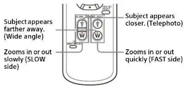
Note
When you perform pan/tilt operations while the camera is in telephoto mode, the moving speed of the image on the screen may be a little jerky.
Adjusting the Camera

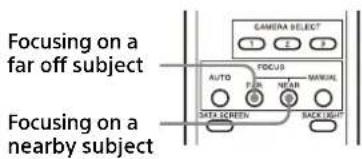
Focusing on a subject
To adjust the focus automatically
Press the AUTO button.
The camera focuses on the subject in the center of the screen automatically.
To adjust the focus manually
After pressing the MANUAL button, press either the FAR or the NEAR button to adjust the focus.
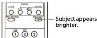
Shooting with back lighting
When you shoot a subject with a light source behind it, the subject becomes dark. In such cases, press the BACK LIGHT button.
To cancel the function, press the BACK LIGHT button again.
Note
The BACK LIGHT button is enabled when MODE (Exposure mode) on the EXPOSURE menu is set to [FULL AUTO] (Full auto), [SHUTTER Pri] (Shutter priority), or [IRIS Pri] (Iris priority).
Storing the Camera Settings in Memory– Preset Feature
Settings, including the camera position, zoom, focus, and backlighting, can be stored in a preset.
You can also store presets from the Administrator menu on a web browser. For details, see "Preset position tab" (page 90).
Notes
The camera supports up to 256 presets. The number of presets that are supported will vary depending on the device used.
- For the RM-IP500 (sold separately), up to 100.
- For the RM-IP10 (sold separately), up to 16.
- For the remote commander (supplied), up to 6.
- For a web browser, up to 256 positions.
For details on the camera settings that can be preset, see "Preset Items and Image Setting File Items" (page 98).
Storing the camera status

1 Press the PAN-TILT RESET button to reset the pan/ tilt position.
2 Adjust the position, zoom, and focus of the camera (See pages 28 and 28).
3 Hold down the PRESET button and press any of the POSITION buttons, 1 to 6, in which you want to store the settings.

Note
Before you store the position, zoom, focus, etc. of the camera, make sure to install and secure the camera in place to use it properly.
Recalling the stored status
Press any of the POSITION 1 to 6 buttons in which you have stored the settings.
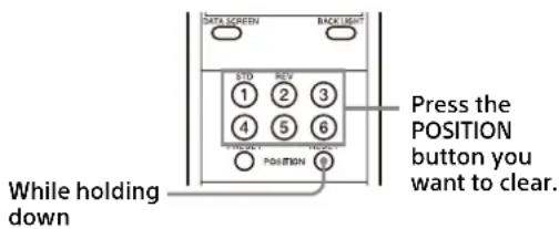
Clearing the preset memory
Hold down the RESET button and press the desired POSITION button 1 to 6 for which you want to clear the settings.
Notes
- If you want to retain the previous pan and tilt positions when the power is turned off and turned on again, store those positions in PRESET 1.
- Storing or clearing the settings in PRESET 1 takes about 2 seconds longer than for other preset operations.
- When you are storing or clearing the settings in one PRESET, you cannot restore, store or clear the settings in another PRESET.
- For details on the items that can be cleared from the memory, see "Preset Items and Image Setting File Items" (page 98).
- When [PRESET MODE] is set to [MODE2] in the SYSTEM menu, only the pan/tilt, zoom, and focus positions of the camera are recalled (BRC-X400/X401).
- You can register or delete the preset even while the menu is being displayed. However, you cannot perform the pan/tilt operation.
- When [PRESET MODE] is set to [TRACE] in the SYSTEM menu, the PTZ trace function works (BRC-X400/X401). For details, see "Storing Camera Pan/Tilt and Zoom Operations – PTZ TRACE function (BRC-X400/X401)" (page 30).
- Note that if you change the image flip setting, the set preset will be cleared.
Storing Camera Pan/Tilt and Zoom Operations
- PTZ TRACE function (BRC-X400/X401)
Up to 16 pan/tilt/zoom operation patterns can be stored for up to 180 seconds.
This allows you to perform quick operations using the remote commander, without displaying the menu. In this case, up to 6 patterns can be stored.
To perform an operation without displaying the menu, set PRESET MODE in the SYSTEM menu (page 46) to TRACE.
To display the menu and perform an operation, see "PTZ TRACE Menu" (page 47).
Notes
- If using the remote commander, pan/tilt and zoom operations cannot be performed simultaneously.
- The menu and camera status are not displayed on the screen.
- All records will be erased if the IMG FLIP setting is changed.
- All PTZ trace records may be erased if you change the video output format.
- Playing a recording will restore CLEAR IMAGE ZOOM and PAN TILT SLOW to their states held during recording.
Recording pan/tilt and zoom operations

1 Adjust the operation start position of the camera.
2 Hold down the PRESET button and press any of the POSITION1 to 6 buttons in which you want to store the settings.
Recording starts.
3 Perform the pan/tilt and zoom operations you want to record.
4 To stop recording, hold down the PRESET button, and press the POSITION button selected in step 2.
Playing pan/tilt and zoom operations
1 Press one of the POSITION1 to 6 buttons. The camera moves the pan/tilt and zoom positions to the playback start position.
2 Press the same POSITION button again. Playback starts.
Note
Playback stops if a pan, tilt, or zoom operation is performed during playback.
Deleting recorded pan/tilt and zoom operations
Hold down the RESET button and press the desired POSITION1 to 6 button for which you want to clear the registered recording.
Operating Menus
This section explains how to configure the camera using the supplied remote commander.
For details on the menu items, refer to page 33 through page 50.
Displaying a menu
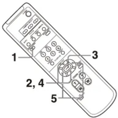
1 Press the DATA SCREEN button. The main menu is displayed.
2 Use the ↑ or ↓ button to move the cursor to the menu item you want to change.
3 Press the HOME button.
The selected menu is displayed.
4 Use the ↑ or ↓ button to move the cursor to the setting item you want to change.
5 Use the ← or → button to change the set value.
Notes
- [IR RECEIVE] cannot be set to [OFF] in the SYSTEM menu when you operate the menu with the supplied remote commander. Set [IR RECEIVE] to [OFF] either using the remote controller or from the Administrator menu on the web browser.
- The menu is not displayed on the SDI output image when the [Menu overlay (SDI)] check box on the Administrator menu is not selected.
- The menu is not displayed on the HDMI output image when the [Menu overlay (HDMI)] check box on the Administrator menu is not selected.
Returning to the main menu
Press the DATA SCREEN button.
Canceling a menu
When the main menu is displayed, press the DATA SCREEN button once. When a setting menu is displayed, press the DATA SCREEN button twice.
Adjusting and Configuring the Camera through On-Screen Menus
About On-Screen Menus
You can configure the shooting conditions and system setup of the camera from the menus displayed on an external monitor. Display settings menus are described as OSD menus in this document.
Menu operations can be performed using the supplied remote commander or a remote controller (sold separately).
For details, refer to the operating instructions of the remote controller.

This section explains how to read the on-screen menus before starting menu operations.
For the overall menu configurations, see page 51.
You can configure the camera from both the OSD menu and the Administrator menu. Bracketed text on the right of the setting item indicates the setting item name of the web browser.
Values to be selected in the OSD menu are noted in square brackets [ ].
Notes
- You cannot perform pan/tilt/zoom operations while the menu is displayed.
- The menus are output through SDI OUT and HDMI OUT.
Confirming selection of menu items and settings/Executing operations
Icons for buttons used for setup operations are displayed along the bottom of the currently displayed menu screen.
▼SELECT or ▲▼▼▼ SELECT: Indicates use of the ↑/↓/◄/→ buttons to select menu items and settings. These correspond to the joystick directions on a remote controller.
ENTERNEXT: Indicates use of the HOME button (equivalent to ENTER) to confirm the menu item or setting selection, or to advance to the next screen or next operation. This corresponds to the joystick button on a remote controller.
MENU EXIT: Indicates use of the DATA SCREEN button (equivalent to MENU) to show/hide the menu screen.
MENUBACK: Indicates that you can return to the main menu by pressing the DATA SCREEN button.
The method used to display the menu will vary depending on the remote controller model. Refer to the operating instructions of the remote controller (sold separately).
Main menu
Press the DATA SCREEN button on the remote commander to display the main menu.

① Cusor
The cursor selects a setting menu. Press the ↑ or ↓ button of the remote commander to move the cursor up or down.
② Menu items
Press the ↑ or ↓ button of the remote commander to select a setting menu, and then press the HOME button to display the selected setting menu.
③ 6ntrol button display section
Setting menu
The setting menu selected on the main menu is displayed.

1 Setting menu
The name of the setting menu currently selected is displayed.
② Cursor
The cursor selects a setting item.
Press the ↑ or ↓ button of the remote commander to move the cursor up or down.
③ Setting items
The setting items for this setting menu are displayed.
Press the or button of the remote commander to select a setting item. Press the ← or → button to change the set value.
4 Se value
The current set values are displayed. Press the ← or → button of the remote commander to change the set value.
⑤ Control button display section
For the default value of each setting item, see "Menu Configuration" (page 51).
Status
Display the items selected in the menu and device information.
EXPOSURE Menu
The EXPOSURE menu is used to set the items regarding the exposure.
You can set the menu from the Administrator menu on a web browser.
For details, see "Picture tab" (page 70).
| <EXPOSURE>MODE | FULL AUTO |
| AE SPEED | 1 |
| EX-COMP | ON |
| LEVEL | -1 |
| GAIN LIMIT | 24dB |
| GAIN POINT | ON |
| POINT POSITION | 6dB |
| MAX SPEED | 1/2000 |
| MIN SPEED | 1/60 |
| BACKLIGHT | OFF |
| SPOTLIGHT | OFF |
| SLOW SHUTTER | ON |
Note
When the high-sensitivity mode is set to ON, the available setting range differs. High-sensitivity mode is set to OFF at the factory settings. To turn it ON, use the VISCA command.
MODE (Exposure - Mode)
[FULL AUTO]: The exposure is adjusted automatically using the gain, electronic shutter speed, and iris setting.
[MANUAL]: You can manually adjust the gain, electronic shutter speed, and iris setting individually.
[SHUTTER Pri]: You can adjust the electronic shutter speed manually. Automatically adjusts the exposure using the gain and iris.
[IRIS Pri]: You can adjust the iris setting manually. Automatically adjusts the exposure using the gain and electronic shutter speed.
When you select any of the above modes, you will see available options for the selected mode among the following setting items.
GAIN (Exposure - Gain)
Select the gain.
When [MODE] is [MANUAL], you can choose a value from 0 to 36 dB (in 3 dB increments). When high-sensitivity mode is set to ON, the available range is expanded from 0 to 48 dB (in 3 dB increments).
SPEED (Exposure - Shutter speed)
When [MODE] is either [MANUAL] or [SHUTTER Pri], select the electronic shutter speed.
When the signal format is 59.94 or 29.97
You can choose from [1/1], [2/3], [1/2], [1/3], [1/4], [1/6], [1/8], [1/10], [1/15], [1/20], [1/30], [1/50], [1/60], [1/90], [1/100], [1/125], [1/180], [1/250], [1/350], [1/500], [1/725], [1/1000], [1/1500], [1/2000], [1/3000], [1/4000], [1/6000], [1/10000].
When the signal format is 50 or 25
You can choose from [1/1], [2/3], [1/2], [1/3], [1/4], [1/6], [1/8], [1/12], [1/15], [1/20], [1/25], [1/30], [1/50], [1/60], [1/100], [1/120], [1/150], [1/215], [1/300], [1/425], [1/600], [1/1000], [1/1250], [1/1750], [1/2500], [1/3500], [1/6000], [1/10000].
When the signal format is 23.98
You can choose from [1/1], [2/3], [1/2], [1/3], [1/4], [1/6], [1/8], [1/12], [1/20], [1/24], [1/25], [1/40], [1/48], [1/50], [1/60], [1/96], [1/100], [1/120], [1/144], [1/192], [1/200], [1/288], [1/400], [1/576], [1/1200], [1/2400], [1/4800], [1/10000].
IRIS (Exposure - Iris)
When [MODE] is either [MANUAL] or [IRIS Pri], you can change the iris setting. You can choose from [F2.0], [F2.2], [F2.4], [F2.6], [F2.8], [F3.1], [F3.4], [F3.7], [F4.0], [F4.4], [F4.8], [F5.2], [F5.6], [F6.2], [F6.8], [F7.3], [F8.0], [F8.7], [F9.6], [F10], [F11], [CLOSE].
AE SPEED (Exposure - AE speed)
Select the adjustment speed for exposure adjustment.
You can adjust the speed at which the camera reaches the optimum exposure setting from [1] (standard) to [48] (slow). Adjust this when the brightness of the object changes instantaneously.
This setting is available when [MODE] is [FULL AUTO], [SHUTTER Pri], or [IRIS Pri].
EX-COMP (Exposure - Exposure compensation)
Turn this [ON] when you want to correct brightness of a picture whose exposure is already automatically adjusted. This setting is available when [MODE] is [FULL AUTO], [SHUTTER Pri], or [IRIS Pri]. The [LEVEL] setting is displayed when this is turned [ON].
LEVEL (Exposure - Exposure compensation)
Set a level to adjust the brightness of a picture whose exposure is already automatically adjusted. Choose a value from [-7] to [+7] for the level.
This is not displayed when [EX-COMP] is turned [OFF].
GAIN LIMIT (Exposure - Auto gain Max. value)
Set the maximum gain when exposure is automatically adjusted using gain. Choose a value from [9dB] to [36dB] (in 3 dB increments). When high-sensitivity mode is set to ON, the available range is expanded from [21dB] to [48dB] (in 3 dB increments).
This setting is available when [MODE] is [FULL AUTO], [SHUTTER Pri], or [IRIS Pri]. You cannot choose a value smaller than the [POINT POSITION] setting.
GAIN POINT (Exposure - Gain point)
When you set [MIN SPEED] to be slower than the output image frame rate, the shutter speed controls exposure based on the [GAIN POINT] setting. Normally, when exposure is controlled with gain, noise becomes prominent if gain is increased to make the image brighter. You can decrease noise by adjusting the exposure with lower shutter speeds after canceling gain adjustments. When you do this, set [GAIN POINT] to [ON] and set the [POINT POSITION] to the gain at which you want the shutter speed to change. When the shutter speed reaches [MIN SPEED] for exposure adjustment, the gain will increase to adjust exposure. This setting is available when [MODE] is either [FULL AUTO] or [IRIS Pri].
POINT POSITION (Exposure - Gain point level)
This is enabled when [GAIN POINT] is turned [ON]. When gain during exposure adjustment reaches the value for [POINT POSITION], exposure is adjusted through a slower shutter speed. This setting is available when [MODE] is either [FULL AUTO] or [IRIS Pri]. You cannot choose a value smaller than the [GAIN] setting.
MAX SPEED (Exposure - Fastest)
Set the maximum (fastest) shutter speed when exposure is automatically adjusted with the electronic shutter.
This setting is available when [MODE] is either [FULL AUTO] or [IRIS Pri]. You cannot choose a value slower than [MIN SPEED].
When the signal format is 59.94 or 29.97
You can choose from [1/30], [1/50], [1/60], [1/90], [1/100], [1/125], [1/180], [1/250], [1/350], [1/500], [1/725], [1/1000], [1/1500], [1/2000], [1/3000], [1/4000], [1/6000], [1/10000].
When the signal format is 50 or 25
You can choose from [1/25], [1/30], [1/50], [1/60], [1/100], [1/120], [1/150], [1/215], [1/300], [1/425], [1/600], [1/1000], [1/1250], [1/1750], [1/2500], [1/3500], [1/6000], [1/10000].
When the signal format is 23.98
You can choose from [1/24], [1/25], [1/40], [1/48], [1/50], [1/60], [1/96], [1/100], [1/120], [1/144], [1/192], [1/200], [1/288], [1/400], [1/576], [1/1200], [1/2400], [1/4800], [1/10000].
MIN SPEED (Exposure - Slowest)
Set the minimum (slowest) shutter speed when exposure is adjusted with the electronic shutter. This setting is available when [MODE] is either [FULL AUTO] or [IRIS Pri]. You cannot choose a value faster than [MAX SPEED].
When the signal format is 59.94 or 29.97
You can choose from [1/1], [2/3], [1/2], [1/3], [1/4], [1/6], [1/8], [1/10], [1/15], [1/20], [1/30], [1/50], [1/60], [1/90], [1/100], [1/125], [1/180], [1/250], [1/350], [1/500], [1/725], [1/1000], [1/1500], [1/2000], [1/3000], [1/4000], [1/6000], [1/10000].
When the signal format is 50 or 25
You can choose from [1/1], [2/3], [1/2], [1/3], [1/4], [1/6], [1/8], [1/12], [1/15], [1/20], [1/25], [1/30], [1/50], [1/60], [1/100], [1/120], [1/150], [1/215], [1/300], [1/425], [1/600], [1/1000], [1/1250], [1/1750], [1/2500], [1/3500], [1/6000], [1/10000].
When the signal format is 23.98
You can choose from [1/1], [2/3], [1/2], [1/3], [1/4], [1/6], [1/8], [1/12], [1/20], [1/24], [1/25], [1/40], [1/48], [1/50], [1/60], [1/96], [1/100], [1/120], [1/144], [1/192], [1/200], [1/288], [1/400], [1/576], [1/1200], [1/2400], [1/4800], [1/10000].
BACKLIGHT (Exposure - Backlight compensation)
This menu allows you to enable/disable backlight compensation so that exposure is optimized for backlight. You can choose either [ON] or [OFF]. This setting is available when [MODE] is [FULL AUTO], [SHUTTER Pri], or [IRIS Pri].
SPOTLIGHT (Exposure - Spotlight compensation)
This menu allows you to enable/disable spotlight compensation by adjusting the exposure darker when a part of the object is bright, such as a person's face in spotlight. You can choose either [ON] or [OFF]. This setting is available when [MODE] is [FULL AUTO], [SHUTTER Pri], or [IRIS Pri]. [SPOTLIGHT] becomes disabled when [BACKLIGHT] is [ON].
SLOW SHUTTER (Exposure - Auto slow shutter)
When you set the mode to [ON], the camera automatically uses slow shutter speed for exposure as the illumination of the object to be shot decreases. This menu is available when [MODE] is [FULL AUTO] or [IRIS Pri].
COLOR Menu
The COLOR menu is used to adjust the white balance and the color.
You can set the menu from the Administrator menu on a web browser.
For details, see "Picture tab" (page 70).
| >WHITE BALANCE MODE | MANUAL |
| R. GAIN | +81 |
| B. GAIN | +47 |
| MATRIX | ON |
| SELECT | STD |
| LEVEL | 4 |
| PHASE | 0 |
| R-G | 0 |
| R-B | 0 |
| G-R | 0 |
| G-B | 0 |
| B-R | 0 |
| B-G | 0 |
WHITE BALANCE MODE (White balance - Mode)
Select a white balance mode.
You can choose from [AUTO1], [AUTO2], [INDOOR], [OUTDOOR], [ONE PUSH], and [MANUAL].
[AUTO1]: Automatically adjusts the color to be closest to the image you are viewing.
[AUTO2]: Automatically adjusts the white balance to reproduce the original colors of the objects, eliminating the influences of ambient illumination.
[INDOOR]: Fixes R/B GAIN when the color temperature is 3200 K.
[OUTDOOR]: Fixes R/B GAIN when the color temperature is 5800 K.
[ONE PUSH]: White balance is adjusted when the ONE PUSH trigger command is received. When you operate from the remote controller, press the O.P.AWB button on RM-IP500 or the ONE PUSH AWB button on RM-IP10. Shoot a large white object in the center of the screen before adjustment. White balance is adjusted when you press the HOME button on the supplied remote commander or the joystick top button on the remote controller while [ONE PUSH] is selected in [WHITE BALANCE MODE] on the menu screen.
[MANUAL]: Allows you to manually adjust the white balance.
When you select any of the above modes, you will see available options for the selected mode among the following setting items.
SPEED (White balance - Speed)
Adjust the speed at which the camera reaches the white convergence point when [AUTO1] or [AUTO2] is chosen. Choose a value from [1], [2], [3], [4], and [5]. [5] is the fastest and [1] is the slowest.
OFFSET (White balance - Offset)
The shift amount of the white convergence point can be adjusted when [WHITE BALANCE MODE] is [AUTO1], [AUTO2], or [ONE PUSH]. The range is from [-7] to [0] to [+7]. White balance is shifted toward blue when a negative value is chosen, and it is shifted toward red when a positive value is chosen.
R.GAIN (White balance - R gain) B.GAIN (White balance - B gain)
Displayed when [MANUAL] is chosen. White balance can be manually adjusted within the range from [-128] to [+127].
MATRIX (Color matrix - Enable) (BRC-X400/X401)
You can emphasize or weaken a specific color region while keeping the white convergence point unchanged. When you turn this [ON], the following items are displayed for adjustment.
SELECT (Color matrix - Matrix) (BRC-X400/X401)
You can choose an internal preset matrix for matrix calculation. You can choose from [STD], [HIGH SAT], [FL LIGHT], [MOVIE], [STILL], [CINEMA], [PRO], [ITU709], and [B&W]. This becomes disabled when [MATRIX] is turned [OFF].
LEVEL (Color matrix - Saturation) (BRC-X400/X401)
You can adjust the color density of the picture. Choose a value in the range from [0] to [14]. The greater the number, the denser the colors, and vice versa. This becomes disabled when [MATRIX] is turned [OFF].
PHASE (Color matrix - Hue) (BRC-X400/X401)
You can adjust the color tone of the entire picture. Choose a value from [-7] to [0] to [+7]. This becomes disabled when [MATRIX] is turned [OFF].
R-G, R-B, G-R, G-B, B-R, B-G (Color matrix - R-G, R-B, G-R, G-B, B-R, B-G) (BRC-X400/X401)
You can set a coefficient for each combination of RGB individually, to adjust the hue of the entire picture.
Choose a value from [-99] to [0] to [+99]. This becomes disabled when [MATRIX] is turned [OFF].
DETAIL Menu
The DETAIL menu is used to adjust the image enhancer function.
You can set the menu from the Administrator menu on a web browser.
For details, see "Picture tab" (page 70).
| <DETAIL> | |
| >MODE | MANUAL |
| LEVEL | 0 |
| BAND WIDTH | DEFAULT |
| CRISPENING | 0 |
| HV BALANCE | 0 |
| BW BALANCE | TYPE2 |
| LIMIT | 3 |
| HIGHLIGHT DETAIL | 0 |
| SUPER LOW | 3 |
MODE (Detail - Mode)
When you choose [AUTO], contour correction signal is automatically added.
When you want to make adjustment by yourself, choose [MANUAL].
Only [LEVEL] will be displayed when you choose [AUTO].
LEVEL (Detail - Level)
You can set the volume of the contour correction signal. Choose a value from [-7] to [0] to [+8] . The greater the value, the stronger the contour correction signal.
BAND WIDTH (Detail - Bandwidth)
You can set the bandwidth for signals undergoing contour emphasis. Choose a bandwidth from [DEFAULT], [LOW], [MIDDLE], [HIGH], and [WIDE]. For example, when you choose [MIDDLE], the middle range of the signals is elevated, and contours in that middle range are emphasized.
CRISPENING (Detail - Crispening)
You can choose the fineness for the objects to which contour correction signals are added.
Choose a value from [0] to [7]. When you choose a higher value, minute contour correction signal elements are removed, and only the high level contour correction signals are left, which reduces noise. When you choose a lower value, minute contour correction signal elements are added to the picture, which increases noise.
HV BALANCE (Detail - HV balance)
You can choose the ratio for horizontal and vertical contour correction signal elements.
Choose a value from [-2] to [0] to [+2] . When you choose a higher value, the horizontal contour
correction elements become greater compared to the vertical elements.
BW BALANCE (Detail - BW balance)
You can adjust the balance between contours in black on the low brightness side of the spectrum and contours in white on the high brightness side. Choose from [TYPE0] to [TYPE4]. The ratio of contours in black is higher for [TYPE0] while the ratio of contours in white is higher for [TYPE4].
LIMIT (Detail - Limit)
You can set the maximum value for the amount of contour emphasis in black on the low brightness side of the spectrum and in white on the high brightness side. Choose a value from [0] to [7].
HIGHLIGHT DETAIL (Detail - Highlight detail)
You can adjust the level of contour added to brightly-lit objects. Choose a value from [0] to [4]. The higher the value, the greater the contour emphasis. Adjust this when you want to emphasize the contour of a brightly-lit object in a bright background.
SUPER LOW (Detail - Super low)
Emphasizes contours in the super low range. Choose a value from [0] to [7]. The greater the value, the greater the contour emphasis. Contrast and resolution increase.
KNEE Menu (BRC-X400/X401)
The KNEE menu is used to adjust the KNEE. You can set the menu from the Administrator menu on a web browser. For details, see "Picture tab" (page 70).
| >SETTING | ON |
| KNEE MODE | MANUAL |
| KNEE SLOPE | +7 |
| KNEE POINT | 5 |
SETTING (Knee - Knee setting)
When you turn this [ON], the following [KNEE MODE] setting items are displayed for adjustment.
KNEE MODE (Knee - Knee mode)
When you choose [AUTO], the KNEE level is automatically calculated based on the brightness level of the picture being shot. When you choose [MANUAL], you can manually adjust the KNEE level irrespective of the brightness level of the picture.
KNEE SLOPE (Knee - Knee slope)
When [KNEE MODE] is [MANUAL], you can adjust the gradient of KNEE (compression rate). Choose a value from [-7] to [0] to [+7]. This is disabled when [KNEE MODE] is [AUTO].
KNEE POINT (Knee - Knee point)
When [KNEE MODE] is [MANUAL], you can adjust the knee point. Choose a value from [0] to [12]. This is disabled when [KNEE MODE] is [AUTO].
GAMMA/VISIBILITY ENHANCER Menu (BRC-X400/X401)
The GAMMA/VISIBILITY ENHANCER menu is used to adjust GAMMA correction and VISIBILITY ENHANCER function.
You can set the menu from the Administrator menu on a web browser.
For details, see "Picture tab" (page 70).
| GAMMA | |
| >SELECT | PATTERN |
| PATTERN | 25 |
| PATTERN FINE | 6 |
| OFFSET | 0 |
| LEVEL | 0 |
| BLACK GAMMA | 0 |
| BLACK GAMMA RANGE | LOW |
| BLACK LEVEL | -48 |
| VISIBILITY ENHANCER | |
| SETTING | ON |
| EFFECT | 0 |
GAMMA
SELECT (Gamma - Gamma)
You can choose the type of basic curve for GAMMA correction.
[STD]: Standard setting (same as the [MOVIE] setting on the camera).
[STRAIGHT]: Set a straight gamma curve.
[PATTERN]: Choose a gamma curve from 512 patterns stored in the camera. You can specify the pattern out of 512 patterns using the following [PATTERN] and [PATTERN FINE]. [PATTERN] defines the upper two digits of the pattern, and [PATTERN FINE] defines the last digit.
[MOVIE]: Use a standard gamma curve for movies.
[STILL]: Use a gamma curve for the tone of a still image.
[CINE1]: Softens the contrast in darker regions and emphasizes gradation changes in lighter regions, producing a subdued tone overall.
[CINE2]: Similar to [CINE1] but optimized for editing with up to 100% video signal.
[CINE3]: Stronger contrast between dark and light regions and greater emphasis on black gradation changes (compared to [CINE1] and [CINE2]).
[CINE4]: Stronger contrast than [CINE3] in darker regions. Compared to the [STD] curve, has
less contrast in darker regions and more contrast in lighter regions.
[ITU709]: Gamma curve equivalent to ITU-709.
PATTERN (Gamma - Pattern)
Choose a value from [0] to [51]. This can be chosen when [SELECT] is set to [PATTERN].
PATTERN FINE
Choose a value from [0] to [9]. When [PATTERN] is [0], [0] cannot be chosen for [PATTERN FINE]. When [PATTERN] is [51], a value larger than [3] cannot be chosen for [PATTERN FINE]. This can be chosen when [SELECT] is set to [PATTERN].
OFFSET (Gamma - Offset)
You can adjust the offset of the output level of gamma curves. Choose a value from [-64] to [0] to [+64].
LEVEL (Gamma - Level)
You can adjust the correction level of the gamma curve. Choose a value from [-7] to [0] to [+7].
BLACK GAMMA (Gamma - Black gamma level)
You can adjust the black gamma level to recreate gradation in the dark areas of the picture or to suppress noise with black-out. Choose a value from [-7] to [0] to [+7] .
BLACK GAMMA RANGE (Gamma - Black gamma range)
You can adjust the brightness range for which the black gamma becomes effective. Choose from [LOW], [MIDDLE], and [HIGH]. The range becomes small when [LOW] is chosen, and it becomes large when [HIGH] is chosen.
BLACK LEVEL (Gamma - Black level)
You can adjust the master black level. Choose a value from [-48] to [0] to [+48].
VISIBILITY ENHANCER
SETTING (Exposure - Visibility Enhancer)
When this is turned [ON], gradation correction is adaptively performed according to the scene being shot.
EFFECT (Exposure - Effect)
You can adjust the brightness of the shadows on the screen. Choose a value from [-3] to [0] to [+3] .
VISIBILITY ENHANCER Menu (SRG-X400/X402/201M2/X120/HD1M2)
You can set the menu from the Administrator menu on a web browser.
For details, see "Picture tab" (page 70).
SETTING
EFFECT
ON
0
SETTING (Exposure - Visibility Enhancer)
When this is turned [ON], gradation correction is adaptively performed according to the scene being shot.
EFFECT (Exposure - Effect)
You can adjust the brightness of the shadows on the screen. Choose a value from [-3] to [0] to [+3] .
ZOOM/FOCUS Menu (BRC-X400/X401, SRG-X400/X402/201M2)
The ZOOM/FOCUS menu is used to select the zoom/focus mode.
You can set the menu from the Administrator menu on a web browser.
For details, see "PTZF control tab" (page 88).
| ZOOM | ||
| >MODE | CLEAR IMAGE ZOOM | |
| FOCUS | ||
| MODE | AUTO | |
ZOOM
MODE (Zoom - Zoom mode)
Select the zoom mode.
[OPTICAL]: Zooms objects within the optical zoom range (up to 20x) of the camera.
[CLEAR IMAGE ZOOM] (Clear Image Zoom): An image is zoomed with less deterioration of image quality over the optical region. Zooming is up to 1.5× when the video output format is 3840×2160, and up to 2× for other formats.
[DIGITAL]: An image can be zoomed up to 20× optical zoom and 12× digital zoom (including Clear Image Zoom) with up to a total of 240× zoom.
FOCUS
MODE (Focus - Focus mode)
Select the focus mode.
[AUTO]: The camera focuses automatically.
[MANUAL]: You can focus manually. Adjust using the supplied remote commander or optional remote controller.
Notes
Select [MANUAL] and adjust the focus manually when shooting the following objects.
- White walls and other objects without contrast
- Objects behind glass
- Objects with horizontal stripes
- Objects on which bright lights are cast or reflected
- Nightscapes and other dark objects with blinking lights
- Lit objects shot with darkened exposure adjustment or exposure compensation settings
FOCUS Menu (SRG-X120/HD1M2)
The FOCUS menu is used to select the focus mode.
You can set the menu from the Administrator menu on a web browser.
For details, see "PTZF control tab" (page 88).
AUTO
MODE (Focus - Focus mode)
Select the focus mode.
[AUTO]: The camera focuses automatically.
[MANUAL]: You can focus manually. Adjust using the supplied remote commander or optional remote controller.
Notes
Select [MANUAL] and adjust the focus manually when shooting the following objects.
- White walls and other objects without contrast
- Objects behind glass
- Objects with horizontal stripes
- Objects on which bright lights are cast or reflected
- Nightscapes and other dark objects with blinking lights
- Lit objects shot with darkened exposure adjustment or exposure compensation settings
PICTURE/OPTICAL FILTER Menu
The PICTURE/OPTICAL FILTER menu is used to adjust picture quality improvement features and optical filters.
You can set the menu from the Administrator menu on a web browser.
For details, see "Picture tab" (page 70).
| PICTURE | |
| HIGH RESOLUTION | OFF |
| >NOISE REDUCTION | ADVANCED |
| 2D NR LEVEL | 3 |
| 3D NR LEVEL | 3 |
| FLICKER CANCEL | ON |
| IMAGE STABILIZER | ON |
| OPTICAL FILTER | |
| IR CUT FILTER | NIGHT |
PICTURE
HIGH RESOLUTION (Picture - High resolution mode)
You can set [HIGH RESOLUTION] (High resolution mode) to [ON] or [OFF]. When set to [ON], you can enjoy emphasized edge and high-resolution images.
Notes
- When set to [ON], image noise may increase more than when set to [OFF].
- When [MODE] is set to [MANUAL] in [DETAIL], the function is not available.
NOISE REDUCTION (Picture - NR mode)
You can obtain clearer images by removing unnecessary noise (fixed pattern and randomized noise) with [NOISE REDUCTION]. Choose from [OFF] or level 1 through level 5. When you select [ADVANCED], you can set up [2D NR LEVEL] and [3D NR LEVEL] independently.
2D NR LEVEL (Picture - 2D NR level)
This is enabled when [NOISE REDUCTION] is [ADVANCED]. Choose from [OFF] or level [1] through level [5] for noise reduction.
3D NR LEVEL (Picture - 3D NR level)
This is enabled when [NOISE REDUCTION] is [ADVANCED]. Choose from [OFF] or level [1] through level [5] for noise reduction.
FLICKER CANCEL (Picture - Flicker cancel)
When this is turned [ON], the flicker correction feature becomes enabled. When this is turned [OFF], the flicker correction feature becomes disabled.
Note
Depending on conditions such as the type of illumination and shutter speed, the flicker correction feature may not be effective. If the frame rate is close to the power supply frequency, the flicker correction feature may not be able to fully remove flickers, even if it is enabled. If this happens, use the electronic shutter.
We recommend to set [FLICKER CANCEL] to [OFF] under lights where no flicker is generated, such as outdoors.
IMAGE STABILIZER (Picture - Image stabilizer)
You can select this function according to the shooting conditions.
[OFF]: The image stabilization feature becomes disabled.
[ON]: The image stabilization feature becomes enabled.
When set to [ON], you can obtain steadier images if vibration is present.
Notes
- The image stabilizer function is not effective during pan/tilt operations. It may take some time for the image to stabilize after performing pan/tilt operations.
- If the image stabilizer function is already enabled, it may take some time for the image to stabilize after turning on the power of the camera.
- Depending on the installation conditions, the image stabilizer may not be effective.
OPTICAL FILTER
IR CUT FILTER (Day/Night ICR - mode)
You can choose either to enable or disable the IR cut filter feature.
By disabling the IR cut filter feature, the gain in the IR region is increased allowing the camera to capture images in shadow.
[DAY]: IR cut filter feature is enabled to remove unnecessary IR.
[NIGHT]: IR cut filter feature is disabled. The picture becomes monochrome.
[AUTO]: The mode is automatically switched to [DAY] or [NIGHT].
Note
When this setting is set to [AUTO], set [EXPOSURE MODE] to [FULL AUTO].
ICR THRESHOLD (Day/Night ICR - Switching level)
When [IR CUT FILTER] is set to [AUTO], choose a level to switch from [NIGHT] to [DAY] in the range from 0 to 255.
The mode is subject to change from [NIGHT] to [DAY] the smaller the chosen value is.
Note
If the larger value is chosen, the mode may not be switched to the DAY mode even when the object is bright. In this case, choose the smaller value.
PAN TILT/PRESET RECALL Menu
The PAN TILT/PRESET RECALL menu is used to select the pan/tilt/preset recall mode.
You can set the menu from the Administrator menu on a web browser.
For details, see "PTZF control tab" (page 88).
| <PAN TILT/PRESET RECALL> | |
| PAN TILT | |
| PAN LIMIT | ON |
| LEFT | +170° |
| RIGHT | -170° |
| TILT LIMIT | ON |
| DOWN | -20° |
| UP | +90° |
| RAMP CURVE | MODE1 |
| PAN TILT SLOW | OFF |
| PRESET RECALL | |
| RECALL SPEED | COMMON |
| COMMON SPEED | 24 |
| PICT FREEZE PRESET | OFF |
PAN TILT
PAN LIMIT (Pan-Tilt - Pan limit)
Set whether to limit the pan rotation range.
[OFF]: Do not apply range limit.
[ON]: Apply range limit.
LEFT (Pan-Tilt - Left)
-170 degrees to +169 degrees, adjustable in 1 degree increment.
RIGHT (Pan-Tilt - Right)
-169 degrees to +170 degrees, adjustable in 1 degree increment.
TILT LIMIT (Pan-Tilt - Tilt limit)
Set whether to limit the tilt rotation range.
[OFF]: Do not apply range limit.
[ON]: Apply range limit.
DOWN (Pan-Tilt - Down)
-20 degrees to +89 degrees when [IMG FLIP] is set to [OFF], and -90 degrees to +19 degrees when [IMG FLIP] is set to [ON], adjustable in 1 degree increment.
UP (Pan-Tilt - Up)
-19 degrees to +90 degrees when [IMG FLIP] is set to [OFF], and -89 degrees to +20 degrees when [IMG FLIP] is set to [ON], adjustable in 1 degree increment.
Setting range of LEFT/RIGHT
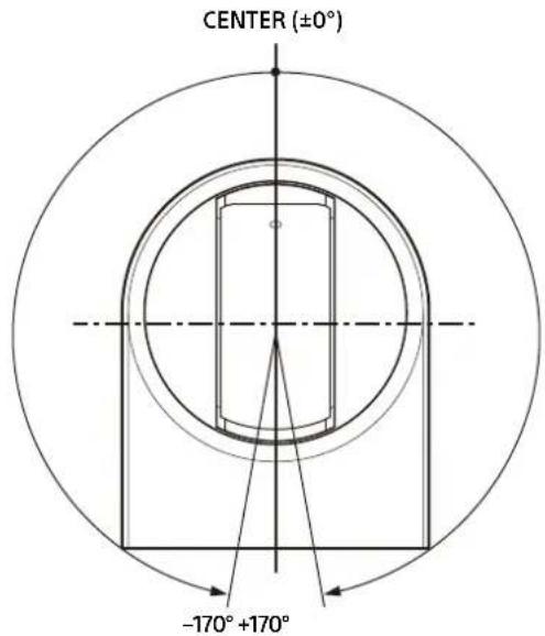
Setting range of DOWN/UP

Notes
- Configure [PAN LIMIT] and [TILT LIMIT] before storing the camera position in a preset memory. If the camera position is out of the range of the [PAN LIMIT] and [TILT LIMIT] settings, you cannot store the camera position in the preset memory.
- When you change the [IMG FLIP] setting in the SYSTEM menu, the [PAN LIMIT] and [TILT LIMIT] settings are reset to the factory settings.
RAMP CURVE (Pan-Tilt - Ramp curve)
Acceleration/deceleration curve for pan and tilt.
Note
This is fixed to [MODE1] for this camera.
PAN TILT SLOW (Pan-Tilt - Slow Pan-Tilt mode)
You can select slow speed panning/tilting.
[OFF]: The camera pans/tilts at the standard speed.
[ON]: The camera pans/tilt speed is slower.
PRESET RECALL
You can select preset recall settings.
RECALL SPEED (Preset - Speed select)
You can select preset recall speed.
[COMPATIBLE]: Wok differently depending on the commands for preset recall.
- For VISCA command: Pan/tilt work with the speed set by each preset.
- For CGI command: P an/tilt work with the speed specified by the CGI command of preset recall.
[SEPARATE]: Pan/tilt work with the speed set by each preset.
[COMMON]: Pan/tilt work with the common speed to all preset.
COMMON SPEED (Preset - Common speed)
This is enabled when [RECALL SPEED] is [COMMON]. Pan/tilt speed for preset recall, which is common to all preset.
PICT FREEZE PRESET (Preset - Pict freeze preset)
You can select output image for preset recall.
[OFF]: Output image directly from the camera.
[ON]: Output frozen image during preset recalling.
PICTURE PROFILE Menu (BRC-X400/X401)
PROFILE NUMBER RECALL: EXECUTE
PP1
*ENTER TO RECALL*
PROFILE NUMBER
Select the picture profile number.
The camera is equipped with 6 types of picture profiles.
You can match the image texture with other types of camcorders that support the picture profile function, or create an image texture that is similar to that of cinematic film.
[PP1]: Set to image quality that uses MOVIE gamma.
[PP2]: Set to image quality that uses STILL gamma.
[PP3]: Set to image quality that uses ITU-709 gamma for natural color tones.
[PP4]: Set to image quality for ITU-709 standard color tones.
[PP5]: Set to image quality that uses CINE1 gamma.
[PP6]: Set to image quality that uses CINE2 gamma.
RECALL: EXECUTE
Recall the selected picture profile.
The following settings are changed when PP1 to PP6 are recalled.
• GAMMA/VISIBILITY ENHANCER SELECT
OFFSET
LEVEL
BLACK GAMMA
BLACK GAMMA RANGE
BLACK LEVEL
VISIBILITY ENHANCER SETTING
• KNEE
SETTING
KNEE MODE
• COLOR
MATRIX
SELECT
LEVEL
PHASE
R-G
R-B
G-R
G-B
B-R
B-G
- DETAIL
LEVEL
MODE
Settings can be adjusted individually after recalling a picture profile.
To save settings, save to a preset.
Notes
- The settings for a picture profile cannot be changed.
- To load preferred settings at startup, recall the picture profile and save it in PRESET 1.
- A picture profile cannot be set from the Administrator menu on the web browser.
VIDEO OUT Menu
You can set [COLOR SPACE] from the
Administrator menu on a web browser.
For details, see "Installation tab" (page 66).
| HDMI | |
| COLOR SPACE | YCbCr |
| H PHASE | |
| H PHASE | 31 |
| H PHASE FINE | 0 |
HDMI
COLOR SPACE (Video out - Color space)
Set the color space of HDMI output.
H PHASE (BRC-X400/X401)
This feature allows you to regulate phase differences between the external sync signal input to the EXT SYNC IN terminal of the camera and the video signal of the camera, when a device which generates the synchronizing signal is connected. The adjustment range is from 0 to 959.
The video signal is advanced in the + direction and delayed in the - direction for the external sync signal.
1 STEP time for [H PHASE] is 0.0135 µ s.
H PHASE
This allows you to adjust by 10 STEP increments.
Choose a value from [0] to [3] to [95].
H PHASE FINE
This allows you to adjust by 1 STEP increment.
Choose a value from [0] to [9].
If you increase the value beyond 9, the tens digit automatically increases (+1 to [H PHASE]).
If you decrease the value beyond 0, the tens digit automatically decreases (-1 to [H PHASE]).
Notes
- [H PHASE] regulates phase differences only for SDI OUT.
- [H PHASE] is not displayed when the SYSTEM SELECT switch, the [VIDEO FORMAT] setting, or [Format] on the Administrator menu is set to 4K.
- [H PHASE] cannot be set from the Administrator menu on the web browser.
SYSTEM Menu
You can set the menu from the Administrator menu on a web browser.
For details, see "Installation tab" (page 66) or "PTZF control tab" (page 88).
| <SYSTEM> | |
| >IMG FLIP | OFF |
| IR RECEIVE | ON |
| TALLY LEVEL | HIGH |
| TELE CONVERT MODE | 2x |
| HTTP/RTSP | OFF |
| PRESET MODE | MODE1 |
IMG FLIP (System - Image flip)
When [IMG FLIP] is set to [ON], the picture is flipped vertically and picture shift direction by the pan/tilt operation is also reversed.
After the [IMG FLIP] setting is changed, turn off the camera and turn it on again to activate the change.
Note
When the [IMG FLIP] setting is changed, the coordinates for pan and tilt are flipped and the following are reset.
- Pan-Tilt limit (PAN-TILT LIMIT)
- Preset
IR RECEIVE (System - IR receive)
If this is turned [OFF], the camera does not receive signals from the supplied remote commander.
Be sure to turn this [ON] when you use the supplied remote commander.
Note
You cannot set [IR RECEIVE] to [OFF] when using the supplied remote commander. Set [IR RECEIVE] to [OFF] using the remote controller (not supplied) or from the Administrator menu on the web browser.
TALLY LEVEL (System - Tally level) (BRC-X400/X401)
This allows you to configure the settings related to the tally lamp on the front of the camera. Choose from [HIGH], [LOW], and [OFF].
[HIGH]: When the tally lamp is turned on, it comes on bright.
[LOW]: When the tally lamp is turned on, it comes on dim.
[OFF]: Even when the tally-lamp-ON command is received, the tally lamp does not light up.
Note
When [TALLY LEVEL] is set to [OFF], the tally lamp does not light up.
TELE CONVERT MODE (System - Tele convert) (BRC-X400/X401, SRG-X402)
You can shoot using 2× magnification.
[OFF]: Does not use the magnification function.
[2x]: Uses the magnification function.
Notes
- This is enabled only when the SYSTEM SELECT switch or the [VIDEO FORMAT] setting is set to 1920×1080.
- The angle of view when [TELE CONVERT MODE] is set to [2x] is narrower than when set to [OFF].
- When used with the image stabilizer function, image quality may be degraded. Set [IMAGE STABILIZER] (Image stabilizer) to [OFF] if desired.
HTTP/RTSP
When the setting of the CAMERA SETUP (camera setup) switch 3 (HTTP/RTSP communication use setting) on the back of the camera is "OFF" (MENU), use this setting to turn ON/OFF the HTTP/RTSP communication. Turn ON the HTTP/RTSP communication to set the camera with the web browser or acquire streaming.
[OFF]: Turn OFF the HTTP/RTSP communication function of the camera.
[ON]: Turn ON the HTTP/RTSP communication function of the camera.
After the [HTTP/RTSP] setting is changed, turn off the camera and turn it on again to activate the change.
Note
[HTTP/RTSP] cannot be set on the web browser.
PRESET MODE (Preset - Preset mode) (BRC-X400/X401)
Set preset mode.
[MODE1]: Recall all saved settings when recalling a preset.
[MODE2]: Recall only the pan, tilt, zoom, and focus positions when recalling a preset.
[TRACE]: You can use the PTZ TRACE function while the OSD menu is hidden.
STANDBY MODE (System - Standby mode)
This is the function to move the pan position to the end automatically when the camera enters in the standby mode.
[NEUTRAL]: The pan position is not moved automatically.
[SIDE]: The pan position is moved to the end automatically.
Notes
- When the mode is set to [SIDE], the pan position is moved to the end, exceeding the limit even if [PAN LIMIT] is specified.
- After the camera is turned on from the standby mode, the camera position moves to the position recorded on PRESET1.
COLOR BAR OVERLAY NAME (BRC-X400/X401)
Select whether to display the camera name when the video signal output from the HDMI OUT or SDI OUT terminal is set to color bar.
[ON]: Display the camera name.
[OFF]: Do not display the camera name.
The camera name to display can be changed from [Camera name] on [Common setting] under the Network tab in the Administrator menu, or from [Name] on RM-IP Setup Tool.
VIDEO FORMAT (System - Video output)
Select the video format of the signal to be output from the HDMI OUT and SDI OUT terminals.
The video format can be changed from this menu when the SYSTEM SELECT switch is set to 6.
When the SYSTEM SELECT switch is set to a value other than 6, the setting status of the SYSTEM SELECT switch and the SDI format level of the CAMERA SETUP switch are displayed.
After the setting is changed, turn off the camera and turn it on again, put the camera in the standby mode and turn it on again, or execute [REBOOT] to reflect the changes.
Select the setting from [2160/29.97p], [1080/59.94p A], [1080/59.94p B], [1080/59.94i], [1080/29.97p], [720/59.94p], [720/59.94p VGA], [2160/25p], [1080/50p A], [1080/50p B], [1080/50i], [1080/25p], [720/50p], [2160/23.98p], or [1080/23.98p].
Notes
- The video format cannot be changed when the SYSTEM SELECT switch is set to a value other than 6.
- For SRG-X400/X402/201M2/X120/HD1M2, you can select 4K only when the 4K Option is installed.
REBOOT
Reboot the camera.
PTZ TRACE Menu (BRC-X400/X401)
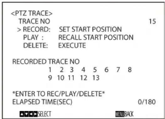
PTZ TRACE is a function used to record pan/tilt/zoom operations, controlled by the remote commander or a remote controller, and then to play back the operations as required. Up to 16 operations can be recorded for up to 180 seconds.
You can set the menu from the Administrator menu on a web browser.
For details, see "PTZ TRACE (BRC-X400/X401)" (page 91).
Notes
- If pan and tilt limits are configured in the PAN TILT/ZOOM menu after recording operations, the pan and tilt limits are not applied upon playback. To use the pan/tilt limit function together, first configure the PAN and TILT settings in the PAN TILT/ZOOM menu and then perform recording operation.
- All records will be erased if the IMG FLIP setting is changed.
- All PTZ trace records may be erased if you change the video output format.
- Playing operations will restore CLEAR IMAGE ZOOM and PAN TILT SLOW to their states held during recording.
TRACE NO: Select the TRACE number to record, play back, or delete.
RECORD: Record operations.
PLAY: Play back the recorded operations.
DELETE: Delete the recorded operations.
RECORDED TRACE NO: Displays the recorded TRACE numbers.
ELAPSED TIME (SEC): Displays the elapsed time during recording or playback in seconds.
The HOME button (equivalent to ENTER) on the supplied remote commander corresponds to the joystick button on an optional remote controller. For details, refer to the operating instructions of the remote controller.
Recording pan/tilt and zoom operations
1 Select the trace number you want to record in TRACE NO.
2 Move the cursor to RECORD, and press the HOME button.
*SETTING (ENTER TO START REC)* is displayed at the bottom of the screen.
3 Move to the record start position, and press the HOME button.
*RECORDING (ENTER TO STOP)* is displayed at the bottom of the screen.
4 Perform the pan/tilt and zoom operations you want to record.
During recording, the ELAPSED TIME (SEC) number at the bottom of the screen increases in increments of 1. During recording, the menu screen display continues.
Note
If using the remote commander, pan/tilt and zoom operations cannot be performed simultaneously.
5 Press the HOME button to stop recording.
The recorded trace number is displayed under RECORDED TRACE NO.
Note
The recording automatically stops after the maximum recording time has elapsed.
Playing pan/tilt and zoom operations
1 Select the recorded trace number you want to play in TRACE NO.
The recorded traces numbers are displayed under RECORDED TRACE NO.
2 Move the cursor to PLAY, and press the HOME button.
*READY FOR PLAY (ENTER)* is displayed at the bottom of the screen, and the camera moves position to the recorded pan/tilt/zoom start position.
3 Press the HOME button to begin playback.
The recorded pan/tilt/zoom operations are played back, and the ELAPSED TIME (SEC) number increases in increments of 1.
During playback, the menu screen display continues, with *PLAYING* displayed at the bottom of the screen.
Note
Playback stops if a pan, tilt, or zoom operation is performed during playback using the remote commander or a remote controller.
Deleting recorded pan/tilt and zoom operations
1 Select the trace number you want to delete in TRACE NO.
2 Move the cursor to DELETE, and press the HOME button.
The recording is deleted, and the corresponding trace number is removed from RECORDED TRACE NO.
STATUS Menu
| PAGE1 | |
| MODE | FULL AUTO |
| AE SPEED | 1 |
| EX-COMP | ON |
| LEVEL | -1 |
| GAIN LIMIT | 24dB |
| GAIN POINT | ON |
| POINT POSITION | 6dB |
| MAX SPEED | 1/2000 |
| MIN SPEED | 1/60 |
| BACKLIGHT | OFF |
| SPOTLIGHT | OFF |
| SLOW SHUTTER | ON |
The STATUS menu is used to display the settings selected with the menus. This menu only displays the current menu settings, and you cannot change them with this menu.
The current menu settings will vary depending on the camera model. Press the ◀ or ➤ button of the remote commander to switch PAGE.
For BRC-X400/X401
PAGE1: It ems in the EXPOSURE menu
PAGE2: Items in the COLOR menu
PAGE3: Items in the DETAIL menu
PAGE4: Items in the KNEE menu
PAGE5: Items in the GAMMA/VE menu
PAGE6: Items in the ZOOM/FOCUS menu
PAGE7: Items in the PICTURE/OPT.FILTER menu
PAGE8: Items in the PAN TILT/PRESET menu
PAGE9: Items in the VIDEO OUT menu
PAGE10: Items in the SYSTEM menu
PAGE11: Device information of the camera and status of switch settings on the back of the camera
PAGE12: Network settings
For SRG-X400/X402/201M2
PAGE1: Items in the EXPOSURE menu
PAGE2: Items in the COLOR menu
PAGE3: Items in the DETAIL menu
PAGE4: Items in the VE menu
PAGE5: Items in the ZOOM/FOCUS menu
PAGE6: Items in the PICTURE/OPT.FILTER menu
PAGE7: Items in the PAN TILT/PRESET menu
PAGE8: Items in the VIDEO OUT menu
PAGE9: Items in the SYSTEM menu
PAGE10: Device information of the camera and status of switch settings on the back of the camera
PAGE11: Network settings
For SRG-X120/HD1M2
PAGE1: Items in the EXPOSURE menu
PAGE2: Items in the COLOR menu
PAGE3: Items in the DETAIL menu
PAGE4: Items in the VE menu
PAGE5: Items in the FOCUS menu
PAGE6: Items in the PICTURE/OPT.FILTER menu
PAGE7: Items in the PAN TILT/PRESET menu
PAGE8: Items in the VIDEO OUT menu
PAGE9: Items in the SYSTEM menu
PAGE10: Dev ice information of the camera and status of switch settings on the back of the camera
PAGE11: Network settings
The [DEVICE INFO] and [NETWORK] screens are only in the STATUS menu.
DEVICE INFO (Device information of the camera and setting status of switches on the back of the camera)
Displays the device information. The Administrator menu is not available for this display.
MODEL NAME (Information - Model Name)
Displays the model name of the camera.
SERIAL NUMBER (Information - Serial number)
Displays the serial number of the camera.
VERSION (Information - Software version)
Displays the software version of the camera.
NAME (Common setting - Camera name)
Displays the name applied to the camera. You can change the name from the Administrator menu on the web browser or RM-IP Setup Tool.
SYSTEM MODE (Video out - Format)
Displays the video output format of the camera.
IR SELECT
Displays the number of the IR SELECT switch on the back of the camera.
SDI LEVEL
Displays the status of SDI LEVEL.
VISCA RATE
Displays the rate of the BAUD RATE SELECT switch on the back of the camera.
4K OPTION (Option - 4K Option) (SRG-X400/X402/201M2/SRG-X120/HD1M2)
Displays installation status of 4K option.
NETWORK
The NETWORK menu is used to configure Network settings.
MAC ADDRESS (Status - MAC address)
Displays the MAC address of the camera.
IP ADDRESS (Status - IP address)
Displays the IP address set up on the camera.
SUBNET MASK (Status - Subnet mask)
Displays the subnet mask currently set up for the camera.
GATEWAY (Status - Default gateway)
Displays the default gateway address currently set up for the camera.
Note
You should set up the IP address, subnet mask, and default gateway before you first use the Network features. Configure these settings using the setup application "RM-IP Setup Tool" on your computer.
For details on the settings, refer to the "RM-IP Setup Tool Guide."
Menu Configuration
The camera menu is configured as described below. For more details, refer to the pages in parentheses. The initial settings of each item are in bold. Only supported functions are displayed.
| EXPOSURE(page 33) | MODE | FULL AUTO, SHUTTER Pri, IRIS Pri, MANUAL |
| GAIN | 0dB, 3dB, 6dB, 9dB, 12dB, 15dB, 18dB, 21dB, 24dB, 27dB, 30dB, 33dB, 36dB (When high-sensitivity mode is set to OFF)0dB, 3dB, 6dB, 9dB, 12dB, 15dB, 18dB, 21dB, 24dB, 27dB, 30dB, 33dB, 36dB, 39dB, 42dB, 45dB, 48dB (When high-sensitivity mode is set to ON) (Adjustable only when MODE in the EXPOSURE menu is set to MANUAL.) | |
| SPEED | For the 59.94 or 29.97 frame rate of video output: 1/1, 2/3, 1/2, 1/3, 1/4, 1/6, 1/8, 1/10, 1/15, 1/20, 1/30, 1/50, 1/60, 1/90, 1/100, 1/125, 1/180, 1/250, 1/350, 1/500, 1/725, 1/1000, 1/1500, 1/2000, 1/3000, 1/4000, 1/6000, 1/10000For the 50 or 25 frame rate of video output: 1/1, 2/3, 1/2, 1/3, 1/4, 1/6, 1/8, 1/12, 1/15, 1/20, 1/25, 1/30, 1/50, 1/60, 1/100, 1/120, 1/150, 1/215, 1/300, 1/425, 1/600, 1/1000, 1/1250, 1/1750, 1/2500, 1/3500, 1/6000, 1/10000For the 23.98 frame rate of video output: 1/1, 2/3, 1/2, 1/3, 1/4, 1/6, 1/8, 1/12, 1/20, 1/24, 1/25, 1/40, 1/48, 1/50, 1/60, 1/96, 1/100, 1/120, 1/144, 1/192, 1/200, 1/288, 1/400, 1/576, 1/1200, 1/2400, 1/4800, 1/10000 (Adjustable only when MODE in the EXPOSURE menu is set to MANUAL or SHUTTER Pri.) | |
| IRIS | F2.0/F2.2/F2.4/F2.6/F2.8/F3.1/F3.4/F3.7/F4.0/F4.4/F4.8/F5.2/F5.6/F6.2/F6.8/F7.3/F8.0/F8.7/F9.6/F10/F11/CLOSE (Adjustable only when MODE in the EXPOSURE menu is set to MANUAL or IRIS Pri.) | |
| AE SPEED | 1 ~ 48 (Adjustable only when MODE in the EXPOSURE menu is set to FULL AUTO, SHUTTER Pri, or IRIS Pri.) | |
| EX-COMP | OFF, ON (Adjustable only when MODE in the EXPOSURE menu is set to FULL AUTO, SHUTTER Pri, or IRIS Pri.) | |
| LEVEL | -7, -6, -5, -4, -3, -2, -1, 0, +1, +2, +3, +4, +5, +6, +7(Adjustable when MODE in the EXPOSURE menu is set to FULL AUTO, SHUTTER Pri, or IRIS Pri, and EX COMP is set to ON.) | |
| GAIN LIMIT | 9dB, 12dB, 15dB, 18dB, 21dB, 24dB, 27dB, 30dB, 33dB, 36dB (When high-sensitivity mode is set to OFF)21dB, 24dB, 27dB, 30dB, 33dB, 36dB, 39dB, 42dB, 45dB, 48dB (When high-sensitivity mode is set to ON)(Adjustable only when MODE in the EXPOSURE menu is set to FULL AUTO, SHUTTER Pri, or IRIS Pri.) | |
| GAIN POINT | OFF, ON (Adjustable only when MODE in the EXPOSURE menu is set to FULL AUTO or IRIS Pri.) | |
| POINT POSITION | 0dB, 3dB, 6dB, 9dB, 12dB, 15dB, 18dB, 21dB, 24dB, 27dB, 30dB, 33dB, 36dB (When high-sensitivity mode is set to OFF)0dB, 3dB, 6dB, 9dB, 12dB, 15dB, 18 dB, 21dB, 24dB, 27dB, 30dB, 33dB, 36dB, 39dB, 42dB, 45dB, 48dB (When high-sensitivity mode is set to ON)(Adjustable when MODE in the EXPOSURE menu is set to FULL AUTO or IRIS Pri, and GAIN POINT is set to ON.) |
| MAX SPEED | For the 59.94 or 29.97 frame rate of video output: 1/30, 1/50, 1/60, 1/90, 1/100, 1/125, 1/180, 1/250, 1/350, 1/500, 1/725, 1/1000, 1/1500, 1/2000, 1/3000, 1/4000, 1/6000, 1/10000For the 50 or 25 frame rate of video output: 1/25, 1/30, 1/50, 1/60, 1/100, 1/120, 1/150, 1/215, 1/300, 1/425, 1/600, 1/1000, 1/1250, 1/1750, 1/2500, 1/3500, 1/6000, 1/10000For the 23.98 frame rate of video output: 1/24, 1/25, 1/40, 1/48, 1/50, 1/60, 1/96, 1/100, 1/120, 1/144, 1/192, 1/200, 1/288, 1/400, 1/576, 1/1200, 1/2400, 1/4800, 1/10000(Adjustable only when MODE in the EXPOSURE menu is set to FULL AUTO or IRIS Pri.) |
| MIN SPEED | For the 59.94 or 29.97 frame rate of video output: 1/1, 2/3, 1/2, 1/3, 1/4, 1/6, 1/8, 1/10, 1/15, 1/20, 1/30, 1/50, 1/60, 1/90, 1/100, 1/125, 1/180, 1/250, 1/350, 1/500, 1/725, 1/1000, 1/1500, 1/2000, 1,3000, 1/4000, 1/6000, 1/10000For the 50 or 25 frame rate of video output: 1/1, 2/3, 1/2, 1/3, 1/4, 1/6, 1/8, 1/12, 1/15, 1/20, 1/25, 1/30, 1/50, 1/60, 1/100, 1/120, 1/150, 1/215, 1/300, 1/425, 1/600, 1/1000, 1/1250, 1/1750, 1,2500, 1/3500, 1/6000, 1/10000For the 23.98 frame rate of video output: 1/1, 2/3, 1/2, 1/3, 1/4, 1/6, 1/8, 1/12, 1/20, 1/24, 1/25, 1/40, 1/48, 1/50, 1/60, 1/96, 1/100, 1/120, 1/144, 1/192, 1/200, 1/288, 1/400, 1/576, 2/1200, 1/2400, 1/4800, 1/10000(Adjustable only when MODE in the EXPOSURE menu is set to FULL AUTO or IRIS Pri.) |
| BACKLIGHT | OFF, ON (Adjustable only when MODE in the EXPOSURE menu is set to FULL AUTO, SHUTTER Pri, or IRIS Pri.) |
| SPOTLIGHT | OFF, ON (Adjustable only when MODE in the EXPOSURE menu is set to FULL AUTO, SHUTTER Pri, or IRIS Pri.) |
| SLOW SHUTTER | OFF, ON (Adjustable only when MODE in the EXPOSURE menu is set to FULL AUTO or IRIS Pri.) |
| COLOR(BRC-X400/X401)(page 35) | WHITE BALANCE | |
| MODE | AUTO1, AUTO2, INDOOR, OUTDOOR, ONE PUSH, MANUAL | |
| SPEED | 1, 2, 3, 4, 5 (Adjustable only when WHITE BALANCE MODE is set to AUTO1 or AUTO2.) | |
| OFFSET | -7, -6, -5, -4, -3, -2, -1, 0, +1, +2, +3, +4, +5, +6, +7(Adjustable only when WHITE BALANCE MODE is set to AUTO1, AUTO2, or ONE PUSH.) | |
| R.GAIN | -128~0~+127 (Adjustable only when WHITE BALANCE MODE is set to MANUAL.) | |
| B.GAIN | -128~0~+127 (Adjustable only when WHITE BALANCE MODE is set to MANUAL.) | |
| MATRIX | OFF, ON | |
| SELECT | STD, HIGH SAT, FL LIGHT, MOVIE, STILL, CINEMA, PRO, ITU709, B&W(Adjustable only when MATRIX is set to ON.) | |
| LEVEL | 0, 1, 2, 3, 4, 5, 6, 7, 8, 9, 10, 11, 12, 13, 14 (Adjustable only when MATRIX is set to ON.) | |
| PHASE | -7, -6, -5, -4, -3, -2, -1, 0, +1, +2, +3, +4, +5, +6, +7 (Adjustable only when MATRIX is set to ON.) | |
| R-G | -99~0~+99 (Adjustable only when MATRIX is set to ON.) | |
| R-B | -99~0~+99 (Adjustable only when MATRIX is set to ON.) | |
| G-R | -99~0~+99 (Adjustable only when MATRIX is set to ON.) | |
| G-B | -99~0~+99 (Adjustable only when MATRIX is set to ON.) | |
| B-R | -99~0~+99 (Adjustable only when MATRIX is set to ON.) | |
| B-G | -99~0~+99 (Adjustable only when MATRIX is set to ON.) | |

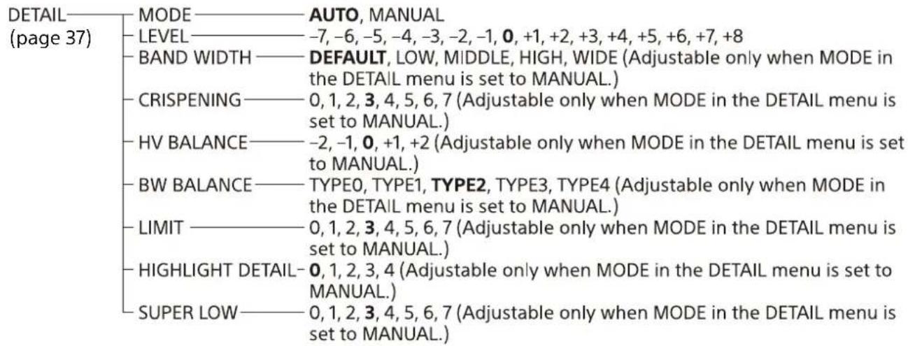

![graph TD A["GAMMA / VISIBILITY ENHANCER (BRC-X400/X401) (page 38)"] --> B["SELECT"] B --> C["STD, STRAIGHT, PATTERN, MOVIE, STILL, CINE1, CINE2, CINE3, CINE4, ITU709"] B --> D["PATTERN"] D --> E["0~25~51 (Adjustable only when SELECT is set to PATTERN.)"] D --> F["PATTERN FINE"] F --> G["0~6~9 (Adjus…](/content/2026/05/1130412/images/15014f8e0ccd7c894e594d5d172917fedf3a274ef4d2be5544320a58ab0b81ec.jpg)

ZOOM/FOCUS ZOOM MODE — OPTICAL, CLEAR IMAGE ZOOM, DIGITAL
(BRC-X400/ FOCUS MODE — AUTO, MANUAL
X401,
SRG-X400/
X402/201M2)
(page 40)
FOCUS——MODE——AUTO, MANUAL
(SRG-X120/
HD1M2)
(page 41)
PICTURE / OPTICAL FILTER (page 41)
PICTURE
HIGH RESOLUTION - OFF, ON
NOISE REDUCTION - OFF, 1, 2, 3, 4, 5, ADVANCED
2D NR LEVEL —OFF, 1, 2, 3, 4, 5 (Adjustable only when NOISE REDUCTION is set to ADVANCED.)
3D NR LEVEL —OFF, 1, 2, 3, 4, 5 (Adjustable only when NOISE REDUCTION is set to ADVANCED.)
FLICKER CANCEL —OFF, ON
IMAGE STABILIZER —OFF, ON
OPTICAL FILTER
IR CUT FILTER —NIGHT, DAY, AUTO
ICR THRESHOLD —0~14~255 (Adjustable only when IR CUT FILTER is set to AUTO.)
PAN TILT / PAN TILT
PRESET — PAN LIMIT — OFF, ON
RECALL (page 43) — LEFT — -170°~+169° (Adjustable only when PAN LIMIT is set to ON.)
RIGHT — -169°~+170° (Adjustable only when PAN LIMIT is set to ON.)
TILT LIMIT — OFF, ON
DOWN — when IMG FLIP is OFF: -20°~+89°
when IMF FLIP is ON: -90°~+19°
(Adjustable only when TILT LIMIT is set to ON)
UP — when IMG FLIP is OFF: -19°~+90°
when IMF FLIP is ON: -89°~+20°
(Adjustable only when TILT LIMIT is set to ON)
RAMP CURVE — MODE1
PAN TILT SLOW — OFF, ON
PRESET RECALL
RECALL SPEED — COMPATIBLE, SEPARATE, COMMON
COMMON SPEED — 1~25 (Adjustable only when RECALL SPEED is set to COMMON.)
PICT FREEZE PRESET — OFF, ON
PICTURE
PROFILE NUMBER—PP1, PP2, PP3, PP4, PP5, PP6
RECALL: EXECUTE
(BRC-X400/
X401)
(page 44)
VIDEO OUT
(BRC-X400/
X401)
(page 45)
HDMI
COLOR SPACE —— YCbCr, RGB
H PHASE
H PHASE —— 0~3~95
H PHASE FINE —— 0~9 (Adjustable when the video format of the camera is set to other than 3840×2160.)

![graph TD A["SYSTEM (BRC-X400/X401) (page 46)"] --> B["IMG FLIP"] B --> C["ON, OFF"] B --> D["IR RECEIVE"] D --> E["ON, OFF"] B --> F["TALLY LEVEL"] F --> G["OFF, LOW, HIGH"] B --> H["TELE CONVERT MODE"] H --> I["OFF, 2x (Only OFF is available when the video output format setting switch is set to oth…](/content/2026/05/1130412/images/7a946642105c8e867dc40c2934198ecdb97856e9fcdcc1fa673b8534624950ef.jpg)
![graph TD A["SYSTEM"] --> B["(SRG-X400/201M2/X120/HD1M2) (page 46)"] B --> C["IMG FLIP"] C --> D["ON, OFF"] B --> E["IR RECEIVE"] E --> F["ON, OFF"] B --> G["HTTP/RTSP"] G --> H["OFF, ON"] B --> I["STANDBY MODE"] I --> J["NEUTRAL, SIDE"] B --> K["VIDEO FORMAT"] K --> L["2160/29.97p*, 1080/59.94p A, 1…](/content/2026/05/1130412/images/26adfd71a39ca5e101e1d9ced4960ac2eeb7095d8c9539db21dd85c2c3c91040.jpg)
![graph TD A["SYSTEM (SRG-X402) (page 46)"] --> B["IMG FLIP"] B --> C["ON, OFF"] B --> D["IR RECEIVE"] D --> E["ON, OFF"] B --> F["TELE CONVERT MODE"] F --> G["OFF, 2x (Only OFF is available when the video output format setting is set to other than 1920x1080.)"] A --> H["HTTP/RTSP"] H --> I["OFF, ON"]…](/content/2026/05/1130412/images/59dbdff37553c78dda94f3dcfb73aa6e1212cfab9f988040e9bdf28b28f7f0a9.jpg)
![graph TD A["PTZ TRACE (BRC-X400/X401) (page 47)"] --> B["TRACE NO"] B --> C["1~16"] B --> D["RECORD: SET START POSITION"] B --> E["PLAY: RECALL START POSITION"] B --> F["DELETE: EXECUTE"] B --> G["RECORDED TRACE NO"] G --> H["1~16"] G --> I["ELASPED TIME(SEC)"] I --> J["0~180"]](/content/2026/05/1130412/images/687490ac79468c0fb7bc178ee5730b476b5ce5a548ce43167a4dd4bfaa3e7751.jpg)
![graph TD A["STATUS (page 49)"] --> B["EXPOSURE"] A --> C["COLOR"] A --> D["DETAIL"] A --> E["KNEE (BRC-X400/X401)"] A --> F["GAMMA/VE (BRC-X400/X401) or VE (SRG-X400/X402/201M2/X120/HD1M2)"] A --> G["ZOOM/FOCUS (BRC-X400/X401, SRG-X400/X402/201M2) or FOCUS (SRG-X120/HD1M2)"] A --> H["PICTURE/OPT.FIL…](/content/2026/05/1130412/images/f30fcfb2407ef487735924d8d4f80590c8ec0ea7c63547aa53889efa45b93f45.jpg)
* When 4K Option is installed
Accessing the Camera from a Web Browser
You can access the camera from a web browser on a computer to upgrade the firmware and to change settings.
An IP address must be set on the camera for access from a web browser. For details on IP address settings, refer to "RM-IP Setup Tool Guide."
Enabling HTTP/RTSP in the Camera
HTTP/RTSP in the camera must be enabled to access the camera from a web browser. To enable/disable the HTTP/RTSP communication, use the CAMERA SETUP (camera setup) switch 3 (HTTP/RTSP communication use setting) on the back of the camera and the OSD menu (SYSTEM - HTTP/RTSP).
| HTTP/RTSP communication use setting | OSD menu (SYSTEM - HTTP/RTSP) | HTTP/RTSP communication |
| ON (FORCED ON) | Enable | |
| OFF (MENU) ON Enable | ||
Notes
- After the CAMERA SETUP (camera setup) switch 3 (HTTP/RTSP communication use setting) on the back of the camera is changed, turn off the camera and turn it on again.
- After the SYSTEM - HTTP/RTSP setting is changed in the OSD menu, restart the camera.
Setting-up the Computer
System configurations required for the Computer are shown in the following (as of May 2021).
OS/Web browser
Windows
OS version Windows 8.1 (64-bit version) Windows 10 (64-bit version) Web browser Google Chrome (Recommended) Microsoft Internet Explorer Ver.11.0
macOS
OS version macOS 10.15
Web browser Google Chrome (Recommended)
CPU
Intel® Core™ 7th generation (Kaby Lake) or later (Recommended)
Memory
8 GB (Recommended)
Display
1920×1080 (Recommended)
Notes
- If the required system configurations are not implemented, or depending on the computer usage status, it may affect video-play operation on a web browser.
- For Internet Explorer used on Windows 8.1, use the Internet Explorer desktop user interface (desktop UI) version.
- For Windows 10, turn off the tablet mode.
- Every page is optimized when the zoom percentage is [100%] and font size is [Medium] on a web browser.
- If an image does not fit to the screen, set the display setting (zoom percentage) of your computer to 100% .
- If you use a display with high pixel density, the zoom percentage may change automatically.
- Web pages displayed when you access the camera are JavaScript. Web pages may not be displayed correctly if some antivirus softwares are used on your computer.
- When you make an SSL connection to the camera with Internet Explorer, you may not be able to access the camera with an IPv6 address. In that case, access the camera with an IPv4 address or consider using Google Chrome.
Accessing the Camera from a Web Browser
Start a web browser on the computer and enter the IP address of the camera in the address bar.
Address
http://192.168.0.100
Authentication by user ID and password is required to access the camera.
Changing the Initial Password
Accessing the camera from a web browser for the first time requires to change the administrator password. The default administrator name and password are as follows. Administrator name: admin Password: Admin_1234
Administrator name should be between 5 and 16 characters and the password should be between 8 and 64 alphanumeric characters. The password must contain alphanumeric characters.
You can turn off the RTSP authentication for H.264/H.265 streaming. When the authentication for viewing H.264 streaming on a web browser is not necessary, uncheck the [RTSP Authentication].
Note
The RTSP authentication setting affects getting the RTSP streaming on programs other than a web browser. When you want to prevent unset users from getting the streaming, turn on the [RTSP Authentication].
Displaying the Viewer Screen Properly
To operate the viewer screen correctly, set the security level of Internet Explorer to [Medium] or lower as follows.
1 Select [Tools] from the menu bar for Internet Explorer, then select [Internet Options] and click the [Security] tab.
2 Click the [Internet] icon (when using the camera via the Internet), or [Local intranet] icon (when using the camera via a local network).
3 Set the security level to [Medium] or lower by the slider (If the slider is not displayed, click [Default Level]).
Note
Up to 5 users can simultaneously access the viewer screen.
When You Use Antivirus Software on Your Computer
- When you use antivirus software, security software, personal firewall, or pop-up blocker on your computer, the camera performance may be reduced, for example, the frame rate for displaying the image may be lower.
- Web pages displayed when you access the camera are JavaScript. Web pages may not be displayed correctly if some antivirus softwares are used on your computer.
When the SSL Function is Used
When Internet Explorer is used
When you enter the camera IP address,
"Certificate Error" may appear according to the status of the certificate set on the camera.
In this case, click [Continue to this website (not recommended)] to continue.
The live viewer window appears (in the SSL communication).
When [Enable (Allow HTTP connection for some clients)] (page 83) is selected
To access the HTTP or SSL connection, enter the following in the address box of the web browser.
For HTTP connection
http://192.168.0.100/index.html
For SSL connection
https://192.168.0.100/index.html
Note
BRC-X401 and SRG-X402/201M2/HD1M2 do not support the SSL function.
Operating the Camera from a Web Browser
This section explains how to monitor the image from the camera using a web browser.
Camera settings should be set by administrator. For details on the camera settings, see "Configuring the Camera from a Web Browser" (page 63).
When you operate pan, tilt, zoom, etc with the remote controller, see "Operations Using the Supplied Infrared Remote Commander" (page 26).
Notes
- Do not operate the camera from a network and with a remote controller simultaneously.
- About 2 minutes after turning on the power, the camera will be automatically reset to the pan/tilt position and the camera settings stored in Preset 1 (Pan/tilt reset). For details on the setting items applied for start-up, see "Preset Items and Image Setting File Items" (page 98).
- If the camera settings are not stored in Preset 1, the camera settings are not stored in the memory and reset to the default settings when the power is turned on.
About Authentication
To access the camera from a web browser, two authentication types are required. Therefore, the authentication screen is displayed twice when you access the camera from a web browser.
HTTP authentication: Sends/receives CGI commands that controls the camera settings.
RTSP authentication: Displays H.264 streaming on a web browser.
When video codec H.265 is applied, One Shot JPEG image is displayed on a web browser and RTSP authentication is not required. RTSP authentication can be turned off in [RTSP Authentication] of the User tab on the Administrator menu.
Note
The RTSP authentication setting affects getting the RTSP streaming on programs other than a web browser. When you want to prevent unset users from getting the streaming, turn on the [RTSP Authentication].
Operating the Camera
This section explains the names and functions of the parts of the live viewer. For details, see the specified pages.
Live viewer
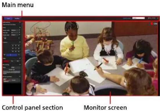
Main Menu
Live
Displays the live viewer window.
Setting
Displays the administrator setting menu (page 64).
You need to log in as an administrator to operate this function.
License notice
Displays the software license agreements, etc.
Language
Set the language to be used in the viewer display.
You can select from [Japanese], [English], [French], [Spanish], [German], [Italian], [Chinese], [Traditional Chinese], [Korean], [Portuguese], [Russian], [Polish], [Hindi], [Vietnamese], [Thai], or [Turkish].
Standby / On
Click to turn on the camera or put it in the standby mode.
1 is displayed when the camera is on standby. Clicking 1 changes the display to ⏻, 1 starts flashing, and then stops flashing when the camera turns on.
Clicking ☐uts the camera in the standby mode and turns the display to ☐
Notes
- Only the administrator can perform this operation.
- You cannot perform this operation if the initial administrator password is not changed.
Control Panel Section
Click to hide the detailed setting screen. Click it again to show the screen.
Information panel

Current date & time
It displays the current date and time set on the camera.
View panel

The screen mode, view size of the image, and image codec can be changed. Still images and videos can be stored (storing video can also be stopped) and audio output volume can be adjusted.
Screen mode
Select the display mode of the live viewer from [Window] or [Full Screen].
View size
Select the image view size on the monitor screen.
Select [ × 1/4 ] to display in one-quarter of the image size.
Select [×1/2] to display in one-half of the image size.
Select [×1] to display the image size selected in [Size] (page 74) of the Video menu.
Select [Full] to display images according to the display size.
Select [Fit] to display images with fixed aspect ratio according to the display size.
Image codec
Select the video mode of the image displayed on the monitor screen from [Image 1], [Image 2], or [Image 3].
You can select [Image 2] or [Image 3] when the codec setting is set to other than Off.
Still image capture
Click to capture a still image shot by the camera and to store it in the computer.
- Start storing Video/ Stop storing Video
Click to start or stop storing the video.
The camera stops storing the video automatically when the storing time exceeds the limit. If you would like to continue storing the video click again.
Notes
- The maximum storing time varies depending on the specifications of the web browser or video codec setting of the camera. Lowering the bit rate setting value of the video codec increases the storing time. Be sure to perform recording tests beforehand and make sure the video is recorded properly.
- While One Shot JPEG image is displayed, you cannot store the video. You cannot start/stop storing video.
- Still images cannot be captured and videos cannot be stored if the protection mode is enabled in Internet Options > Security properties in Control Panel of Windows.
Volume control
This is displayed when you check [Enable] in the Audio tab of the Audio menu.

Use the slide bar to adjust the volume for audio output.
When you click 📄 the icon is changed to 🎩 and audio does not output from the speaker. To output audio again, click 🎩
Notes
- While One Shot JPEG image is displayed, audio is not output. Volume control is not displayed.
- When you open the live screen, audio output is stopped in the default setting. To output audio, click fore use.
Camera panel

By using the control panel, you can operate the pan/tilt, moving to the home position, zoom, and focus of the camera for the monitor image currently displayed.
Pan/Tilt control
Click the arrow button of the direction you want to turn the camera. To turn the camera continuously, click and hold the arrow button. Click ▶ to return to the front.
Zoom control
Click to zoom out and click to zoom in.
Zoom continues while the button is being clicked.
BRC-X400/X401, SRG-X400/X402/201M2

SRG-X120/HD1M2
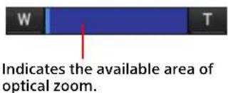
Focus control
This function is displayed when [Focus mode] is set to [Manual] in the PTZF control menu (page 88).
Tally panel (BRC-X400/X401)

Tally lamp control
Clicking the [On]/[Off] button controls the tally lamp on the camera. The indicator lights up when the tally lamp is [On]. It does not light up when the tally lamp is [Off].
Streaming panel
Mode
The streaming mode currently selected is displayed.
When the mode is RTMP or SRT-Caller, the start and stop buttons for control streaming and the streaming URL are displayed.
Preset position panel
For BRC-X400/X401, the panel is displayed when [Mode1] or [Mode2] is selected for the preset mode on the PTZF operation tab.

Preset control
This is displayed only when preset positions for the camera are stored in memory.
Stored preset positions are displayed. If you select a thumbnail when storing a preset position, it will be displayed with a thumbnail. When you select the preset position name from the list, the camera will turn to the position that you have stored in memory in the Preset position menu.
PTZ trace panel (BRC-X400/X401)
Displayed when [Trace] is selected for the preset mode in the PTZF control tab.

PTZ Trace control
Display only the PTZ traces with pan/tilt/zoom operations recorded. The PTZ traces are displayed with the thumbnail if it is registered. You can play back the pan/tilt/zoom operations recorded in PTZ trace from the list. Playback operation is prepared on the first selection and playback starts on the second.
Monitor Screen
Streaming video from the camera is displayed.
- Video mode image selected in [Image codec] is displayed.
For H.264, the video is displayed. However, when the RTSP streaming is not enabled, the image is displayed after obtaining One Shot JPEG.
For H.265, the image is displayed after obtaining One Shot JPEG.
- The video is displayed in size selected in [View size].
- When the streaming mode is RTMP or SRT-Caller, "● Live" is displayed in the upper right of the video image with the red frame on the entire image while streaming.
Configuring the Camera from a Web Browser
This section explains how to set the functions of the camera by an administrator.
For details on monitoring of the camera image, see "Operating the Camera from a Web Browser" (page 60).
To configure the camera with the remote commander, see "Operations Using the Supplied Infrared Remote Commander" (page 26).
This section explains the basic operations for setting the Administrator menu, then explains each option in the menu.
Note on the display of menu options
Only the current available options in the setting menus of the camera are clearly displayed.
Grayed out options are not available.
Only supported functions are displayed.
Basic Operations of the Administrator Menu
You can set all functions of the camera in the Administrator menu according to the user's usage. Click [Setting] on the viewer screen to display the Administrator menu.
How to set up the Administrator menu
1 Access the camera to display the viewer screen. For details, see "Accessing the Camera from a Web Browser" (page 58).
2 Click [Setting] on the main menu. The authentication dialog appears when you do not perform the viewer screen authentication procedure as an administrator. When you enter the user name and password for administrator, the Administrator menu appears.
3 Click the menu (example: System) on the left of the Administrator menu. The selected menu is displayed.
Example: [System] menu

4 Select the desired tab above the menu and set each option in the tab.
Example: [Date & time] tab of the [System] menu

For details on the menu tabs and setting options, see page 65.
5 After the settings are completed, click [OK]. The settings you have made become active.
Click [Cancel] to nullify the settings and return to the previous settings.
Common buttons in each menu
The following common buttons are displayed in the tab of each menu as required.
OK
Click to enable the settings in each tab. The settings are not applied to the camera until you click this button.
Cancel
Click to nullify the settings and return to the previous settings.
Reload
Click to cancel the operation changed on a web browser and update the display on a web browser after obtaining the information from the camera.
Notes for all aspects of the menu
- After changing a setting on a menu, wait at least 2 minutes before powering off the camera. If you power off the camera immediately, the changed setting may not be stored correctly.
- Even though the camera settings are changed while viewing on the live viewer, some settings are not applied. To apply the changes to the opening live viewer, click [Refresh] on a web browser.
- You can configure the camera from both the OSD menu and the Administrator menu on the web browser. Bracketed text on the right of the setting item indicates the setting item name of the OSD menu.
- Values to be selected in the Administrator menu are noted in square brackets [ ].
Configuration of the Administrator Menu
System menu
Displays the System menu ("Configuring the System — System Menu" (page 65)).
Video menu
Displays the Video menu for setting the camera image ("Setting the Camera Image — Video Menu" (page 70)).
Audio menu
Displays the Audio menu for setting the camera audio ("Setting the Audio — Audio Menu" (page 77)).
Network menu
Displays the Network menu for setting the network connection ("Configuring the Network — Network Menu" (page 78)).
Security menu
Displays the Security menu for setting the login user and specifying the computer(s) connected to the camera ("Setting the Security — Security Menu" (page 81)).
PTZF control menu
Displays the PTZF control menu for pan, tilt, zoom, and focus operations and serial communication setting ("Setting the PTZF Control — PTZF control Menu" (page 88)).
Streaming menu
Displays the Streaming menu for distribution settings ("Setting the Streaming — Streaming Menu" (page 92)).
Configuring the System — System Menu
When you click 📋 Systeme Administrator menu, the System menu appears.
Use this menu to set the basic settings of the camera.
The System menu consists of the [Information], [Date & time], [Installation], [Initialize], [System log], and [Access log] tabs.
Information tab
You can also refer from the OSD menu. For details, see "DEVICE INFO (Device information of the camera and setting status of switches on the back of the camera)" (page 49).

Information
Model Name (DEVICE INFO - MODEL NAME)
Displays the model name of the camera.
Serial number (DEVICE INFO - SERIAL NUMBER)
Displays the serial number of the camera.
Software version (DEVICE INFO - VERSION)
Displays the software version of the camera.
Date & time tab

Date & time
Current date & time
Displays the date and time set on the camera.
Notes
- Time may not be set correctly at the time of purchase. Be sure to check the date and time of the camera and set as necessary.
- Time setting is initialized at factory default settings.
PC clock
Displays the date and time set on your computer.
Date & time format
Select the date and time format to be displayed on the viewer from the drop-down list. You can select the format from [yyyy-mm-dd hh:mm:ss] (year-month-day hours:minutes:seconds), [mm-dd-yyyy hh:mm:ss] (month-day-year hours:minutes:seconds), and [dd-mm-yyyy hh:mm:ss] (day-month-year hours:minutes:seconds).
Time setting
Select how to set the date and time.
[Keep current setting]: Select when you do not set the date and time of the camera.
[Synchronize with PC]: Select when you synchronize the date and time between the camera and the computer.
[Manual setting]: Select when you set the date and time of the camera manually.
Select the year, month, day, hours, minutes, and seconds from each drop-down list.
[Synchronize with NTP]: Select when you synchronize the date and time between the camera and the time server called NTP (Network Time Protocol) server. Set the NTP server when [Synchronize with NTP] is selected.
NTP Auto
Select the checkbox when you obtain the NTP server information from the DHCP server.
Clear the checkbox when you specify the NTP server directly.
NTP server
When [NTP Auto] is not selected, specify the NTP server for synchronization.
NTP interval
Specify the interval for time synchronization with the NTP server.
You can set from 100 to 86,400 seconds.
Time zone
Set the time difference from Greenwich Mean Time according to the area where the camera is installed. Select the time zone of the area where the camera is installed from the drop-down list.
Automatically adjust clock for daylight saving time changes
The clock time is automatically adjusted according to the daylight saving time of the selected time zone.
Note
If the time zone selected in [Time zone] is different from that set on the computer, the date and time applied the time zone difference to are set on the camera.
Installation tab

Use this tab to perform settings related to installation.
You can configure the settings from the OSD menu. For details, see "SYSTEM Menu" (page 46) or "VIDEO OUT Menu" (page 45).
System
Image flip (SYSTEM - IMG FLIP)
Flip an image vertically. Normally clear the checkbox before use. Select the checkbox when installing the camera on the ceiling.
Note
When the [Image flip] setting is changed, the coordinates for pan and tilt are flipped and the following are reset.
-Pan-Tilt limit (PAN-TILT LIMIT)
-Preset
IR receive (SYSTEM - IR RECEIVE)
If you clear the checkbox, the camera does not receive signals from the supplied remote commander. Be sure to select the checkbox when you use the supplied remote commander.
Tally level (SYSTEM - TALLY LEVEL) (BRC-X400/X401)
This is the setting related to the tally lamp.
[High]: Brightens the tally lamp.
[Low]: Darkens the tally lamp.
[Off]: Even when the tally-lamp-ON command is issued, the tally lamp does not light up.
Tele convert (SYSTEM - TELE CONVERT MODE) (BRC-X400/X401, SRG-X402)
When this is selected, you can shoot using 2× magnification.
Notes
- This is enabled only when the SYSTEM SELECT switch or format setting of video output is set to 1920×1080.
- Selecting the checkbox of [Tele convert] narrows the angle of view.
Menu overlay (SDI)
Clearing the checkbox does not display the OSD menu or message on the SDI output screen.
Menu overlay (HDMI)
Clearing the checkbox does not display the OSD menu or message on the HDMI output screen.
Standby mode (SYSTEM - STANDBY MODE)
This is the function to move the pan position to the end automatically when the camera enters in the standby mode.
[Neutral]: The pan position is not moved automatically.
[Side]: The pan position is moved to the end automatically.
Notes
- When the mode is set to [Side], the pan position is moved to the end exceeding the limit even if the Pan-Tilt limit is specified.
• After the camera is turned on from the standby mode, the camera position moves to the position recorded on PRESET1.
Video out
Format (DEVICE INFO - SYSTEM MODE)
Select the video output format of the signal to be output from the HDMI OUT and SDI OUT terminals. You can change the video format from this menu when the SYSTEM SELECT switch is set to 6. When the SYSTEM SELECT switch is set to a value other than 6, the setting status of the SYSTEM SELECT switch and the format level of the CAMERA SETUP switch are displayed.
| Video output format | |
| 59.94 Hz system 3 | 840×2160/29.97p |
| 1920×1080/59.94p (Level A) | |
| 1920×1080/59.94p (Level B) | |
| 1920×1080/59.94i | |
| 1920×1080/29.97p | |
| 1280×720/59.94p | |
| 1280×720/59.94p (HDMI: VGA) | |
| 50 Hz system 3840 | 0×2160/25p |
| 1920×1080/50p (Level A) | |
| 1920×1080/50p (Level B) | |
| 1920×1080/50i | |
| 1920×1080/25p | |
| 1280×720/50p | |
| 24 Hz system 3840 | 0×2160/23.98p |
| 1920×1080/23.98p |
Notes
- [3840×2160/29.97p], [3840×2160/25p], and [3840×2160/23.98p] are output only from HDMI. They are not output from SDI.
- When [1280 × 720 / 59.94p (HDMI:VGA)] is displayed, [1280 × 720 / 59.94p] is output only from SDI, and HDMI output at this time is VGA.
- You cannot change the video format when the SYSTEM SELECT switch is set to a value other than 6.
- For SRG-X400/X402/201M2/X120/HD1M2, you can select 4K only when the 4K option is installed.
Color space (VIDEO OUT - COLOR SPACE)
You can set the color space of HDMI output.
Initialize tab

Initialize
Reboot
Used when forcibly rebooting the system.
When you click [Reboot], the message "This System will be rebooted. Are you sure?" appears. Click [OK] to reboot the camera. It takes about 2 minutes to reboot.
Factory default
Resets the camera to the default settings.
Retain current network settings
When this is selected, the current network and security settings can be retained even when the camera is reset to the factory default settings. When you click [Factory default], the message "This System will be rebooted. Are you sure?" appears. When you click [OK], the network indicator on the camera starts to flash. When the default settings are completed, the camera reboots automatically. Do not turn off the camera before the camera reboots.
Tip
The camera can be reset to the factory default settings by pressing the reset switch for 5 seconds or longer.
Delete superimpose logo
Click [Delete] to delete the superimpose logo, specified at [Position] in the Superimpose tab of the Video menu, from the camera.
To set whether to show or hide the superimpose logo, configure the setting in the Superimpose tab.
Export/Import
Export setting file
Used when you export the setting data of the camera in a file.
To export the setting data of the camera to the computer as a file, click [Export] and specify the destination folder according to the instructions on a web browser.
Import setting file
Used when you import the stored setting data of the camera.
Click [Choose File] to select the setting file. The camera is configured according to the setting data.
Notes
- The following items cannot be exported or imported in [Export setting file] or [Import setting file].
- Network settings
- QoS settings
- User settings
- Access limit settings
- 802.1X function settings/certificate
- SSL function settings/certificate
- Referer check settings
- Brute force attack protection settings
- Superimpose logo
- Preset settings
– Preset items (page 98) - PTZ trace settings
- NDI|HX settings
- The Video codec setting is not restored if there is an image size or frame rate that the stored setting by changing the SYSTEM SELECT switch or format setting of video output cannot be applied on.
Version up
Firmware upgrade
Use this to upgrade the firmware. Click [Choose File] to select the desired firmware file.
The confirmation dialog is displayed. Follow the online instructions.
System log tab
System log
Software performance data of the camera is recorded in the log. It includes useful data for troubleshooting.
Click [Reload] to reload the latest data.
Log level
Set the range of data recorded in the camera.
Log size
Set the maximum number of data recorded in the camera.
Download as file
Logs recorded in the camera can be stored as files.
Access log tab
Access log
Displays the access history of the camera.
Click [Reload] to reload the latest data.
Log level
Set the range of data recorded in the camera.
Log size
Set the maximum number of data recorded in the camera.
Download as file
Logs recorded in the camera can be stored as files.
Service tab
Consent
I agree to download device information.
Download the device information data to use for service.
Select the checkbox of [I agree to download device information.] and click [OK] for download.
Device information
Select the checkbox of [I agree to download device information.] and click [OK] for display. To save the device information, click [Device information] and specify the destination folder according to the instructions on a web browser.
Data file will be saved in binary format.
Option tab (SRG-X400/X402/201M2/X120/HD1M2)
Perform license settings to enable optional functions of the camera.
Device unique ID
Display the ID used when purchasing a license.
4K option
Display the 4K option status.
[Enable]: The 4K option is installed.
[Disable]: The 4K option is not installed.
License file
Select the license file to install and upload on the camera.
Note
When the camera is reset to the factory default settings, the uploaded license will be deleted.
Reinstall the license to enable the 4K option again.
To Enable the Optional Function by Purchasing a License
You can use optional functions by purchasing a license and installing the license file. Before performing this operation, purchase a license in advance and obtain the purchase code.
Note
For details on how to purchase a license, contact a distributor.
Perform operations of steps 1 and 3 on the Administrator menu of the camera. For step 2, access the designated website using a web browser and follow on screen instructions.
1 Access the device on which you use optional functions, and check the Device unique ID on the [Option] tab in the [System] under the Administrator setting menu.
2 Access "Upgrade and License Management Suite" using a web browser. URL:https://ulms.sony.net
2-1 Following on screen instructions, register the license purchase code and enter the Device unique ID you checked in step 1.
2-2 Download the issued license file. (installation key: RQ_LIC.DAT)
3 Perform the following operations on the [Option] tab in the [System] under the Administrator setting menu.
3-1 Click [Choose File] on [License file] and select the license file downloaded in step 2-2. (installation key: RQ_LIC.DAT)
3-2 When the dialog pops up, click [OK], and upload the license file.
3-3 Confirm that the [4K option] status is displayed as [Enable].
Note
You cannot install the license file if the Device unique ID used to issue the file does not match the one of the devices in which you install the license file. Be sure to enter the Device unique ID of the device on which you use optional functions.
Setting the Camera Image — Video Menu
Picture tab
You can configure the settings from the OSD menu. For details, see "EXPOSURE Menu" (page 33), "COLOR Menu" (page 35), "DETAIL Menu" (page 37), "KNEE Menu (BRC-X400/X401)" (page 38), "GAMMA/VISIBILITY ENHANCER Menu (BRC-X400/X401)" (page 38), "VISIBILITY ENHANCER Menu (SRG-X400/X402/201M2/X120/HD1M2)" (page 39), or "PICTURE/OPTICAL FILTER Menu" (page 41).
Export/Import (Picture setting file)
You can export the picture settings of the camera as a picture setting file, or import picture setting files saved in the computer to reflect them on the camera. See "Preset Items and Image Setting File Items" (page 98) for items you can export or import by picture setting files.
Export picture setting file
Export the current picture setting information as a picture setting file to the computer. The dialog to select the destination appears by clicking [Export]. Select the destination to export the picture setting file.
Import picture setting file
Reflect the picture setting file on the camera by importing the file saved in the computer. The dialog appears by clicking [Choose File]. Select the file. After selecting the file, click [OK] on the pop-up screen to reflect the settings on the camera, and then the Picture tab will be reloaded.
Keep current picture settings after reboot
Save to Preset 1
The picture setting registered to Preset 1 is applied to the camera when you turn it on. After importing the picture setting file, or after changing the picture setting on the Menu, click [Save] to register the setting to Preset 1.
Notes
- The items to be saved are the contents of picture setting files imported in advance and the items changed on the Picture tab afterward.
- You cannot import/export picture setting files from the OSD menu.
- The other setting items registered to Preset 1 in advance are not changed. See "Preset Items and Image Setting File Items" (page 98) for the other setting items.
Exposure
Mode (EXPOSURE - MODE)
Adjust the exposure settings.
[Full auto]: The camera performs gain, iris, and shutter speed adjustments automatically.
[Shutter priority]: The camera performs gain and iris adjustments automatically, and you can select shutter speed.
[Iris priority]: The camera performs gain and shutter speed adjustments automatically, and you can select iris (aperture).
[Manual]: You can manually adjust gain, iris, and shutter speed.
Note
Depending on the setting options, the range set by turning On/Off the high-sensitivity mode may differ. You cannot set the high-sensitivity mode from the menu. With reference to the Command List, change the setting from the VISCA/CGI command.
Visibility Enhancer (VISIBILITY ENHANCER - SETTING)
In high-contrast scenes such as against a back light, this function reduces overexposure and underexposure. Selecting the checkbox enables the function.
Effect (VISIBILITY ENHANCER - EFFECT)
Set the level of Visibility Enhancer.
Iris (EXPOSURE - IRIS)
Select the iris value from the drop-down list. This function can be selected only when [Mode] is set to [Iris priority] or [Manual].
Gain (EXPOSURE - GAIN)
Select the gain from the drop-down list. This function can be selected only when [Mode] is set to [Manual].
Auto gain Max. value (EXPOSURE - GAIN LIMIT)
Select the maximum gain value of automatic exposure control from the drop-down list. This function can be selected only when [Mode] is set to [Full auto], [Shutter priority], or [Iris priority]. You cannot set the value lower than [Gain point level].
Gain point (EXPOSURE - GAIN POINT)
When you set [Slowest] (lower limit of the shutter speed) to be lower than the output image frame rate, the shutter speed controls exposure based on the [Gain point] setting. Normally, when exposure is adjusted with sensitivity, noise is prominent when sensitivity is increased to brighten the image. You can decrease noise by adjusting the exposure through lower shutter speeds instead of adjusting with sensitivity. When the exposure is adjusted, select the checkbox of [Gain point] and set [Gain point level] to the value of sensitivity position that exposure is adjusted through shutter speeds. When shutter speeds reaches [Slowest] for exposure adjustment, sensitivity will increase again to adjust exposure. This setting is available when [Mode] is set to [Full auto] or [Iris priority].
Gain point level (EXPOSURE - POINT POSITION)
This is enabled when the checkbox of [Gain point] is selected. When sensitivity during exposure adjustment reaches the value of [Gain point level], exposure will be adjusted through a lower shutter speed.
You cannot select a value that exceeds [Auto gain Max. value].
This setting is available when [Mode] is set to [Full auto] or [Iris priority] and the checkbox of [Gain point] is selected.
Shutter speed (EXPOSURE - SPEED)
Select shutter speed from the drop-down list. This function can be selected only when [Mode] is set to [Shutter priority] or [Manual].
Note
When you switch to the shutter speed value with a great change, it may take some time to apply the setting value.
During that time, the setting value on the display does not match with the actual setting value. By reloading the web browser, the correct setting value is displayed.
Fastest (EXPOSURE - MAX SPEED)
Set the maximum shutter speed.
This setting is available when [Mode] is set to [Full auto] or [Iris priority].
Slowest (EXPOSURE - MIN SPEED)
Set the minimum shutter speed.
This setting is available when [Mode] is set to [Full auto] or [Iris priority].
Auto slow shutter (EXPOSURE - SLOW SHUTTER)
Select the checkbox to enable the auto slow shutter function. This function can be selected only when [Mode] is set to [Full auto].
Exposure compensation (EXPOSURE - EX-COMP, LEVEL)
Select the exposure correction value from the drop-down list to adjust the target brightness for the automatic exposure setting. Selecting higher value brightens the image and lower value darkens the image. This function can be selected only when [Mode] is set to [Full auto], [Shutter priority], or [Iris priority].
Backlight compensation (EXPOSURE - BACKLIGHT)
Select the checkbox to enable the backlight compensation function. This function can be selected only when [Mode] is set to [Full auto], [Shutter priority], or [Iris priority].
Spotlight compensation (EXPOSURE - SPOTLIGHT)
It darkens the exposure when a part of the object is bright, such as a spotlighted face. Spotlight compensation function is disabled when the checkbox of [Backlight compensation] is selected. This setting is available when [Mode] is set to [Full auto], [Shutter priority], or [Iris priority].
AE speed (EXPOSURE - AE SPEED)
Select the adjustment speed for exposure adjustment.
You can select the speed at which the camera reaches the optimum exposure setting from 1 (standard) to 48 (slow). Select when the brightness of the object changes instantaneously.
This setting is available when [Mode] is set to [Full auto], [Shutter priority], or [Iris priority].
White balance
Mode (COLOR - WHITE BALANCE MODE)
Select a white balance mode.
[Auto1]: Automatically adjusts the color reproduction closer to the image you are viewing (approximately 2500 K to 7500 K).
[Auto2]: Eliminating the influences caused by environmental illumination or lights, automatically adjusts the color reproduction closer to the original color of the object (approximately 2000 K to 10000 K).
[Indoor]: Set a white balance suitable for indoor photography.
[Outdoor]: Seta white balance suitable for outdoor photography.
[One push WB]: Select to enable [Offset] and [One push trigger].
[Manual]: Set [R gain] and [B gain]. Select gain values from 0 to 255.
Speed (COLOR - SPEED)
When [Mode] is set to [Auto1] or [Auto2], you can adjust the speed at which the camera reaches the white convergence point. Select a value from [1], [2], [3], [4], or [5]. [5] is the fastest and [1] is the slowest.
Offset (COLOR - OFFSET)
When [Mode] is set to [Auto1], [Auto2], or [One push WB], you can adjust the shift amount of the white convergence point in a range from 0 to 14. White balance is shifted toward blue when a lower value is selected, and it is shifted toward red when a higher value is selected.
One push trigger (COLOR - ONE PUSH TRIGGER)
Click [On] to adjust the white balance. Shoot and zoom a large white object in the center of the screen before adjustment.
R gain (COLOR - R.GAIN)
White balance can be manually adjusted in a range from 0 to 255.
This setting is enabled only when [Mode] is set to [Manual].
B gain (COLOR - B.GAIN)
White balance can be manually adjusted in a range from 0 to 255.
This setting is enabled only when [Mode] is set to [Manual].
Color matrix (BRC-X400/X401)
Enable (COLOR - MATRIX)
Enables the color matrix setting.
Matrix (COLOR - SELECT)
Select an internal preset matrix for matrix calculation. You can select from [STD], [HIGH SAT], [FL LIGHT], [MOVIE], [STILL], [CINEMA], [PRO], [ITU709], or [B&W]. This setting is available when the checkbox of [Enable] is selected.
Saturation (COLOR - LEVEL)
Adjust the color density of the image. Select a value from [0] to [14]. The higher the value, the darker the color and the smaller the value, the lighter the color. This setting is available when the checkbox of [Enable] is selected.
Hue (COLOR - PHASE)
Adjust the color tone of the entire video. Select a value from [-7] to [0] to [+7]. This setting is available when the checkbox of [Enable] is selected.
R-G, R-B, G-R, G-B, B-R, B-G (COLOR - R-G, R-B, G-R, G-B, B-R, B-G)
Adjusts the hue in the range of [-99] to [99]. This setting is available when the checkbox of [Enable] is selected.
Detail
Select the sharpness.
Mode (DETAIL - MODE)
When you select [Auto], contour correction signal is automatically added.
When you make adjustment manually, select [Manual].
Only [Level] is displayed when you select [Auto].
Level (DETAIL - LEVEL)
The higher the value, the sharper the image. The lower the value, the softer the image.
You can select from [-7] (MIN) to [0] to [+8] (MAX).
Bandwidth (DETAIL - BAND WIDTH)
You can set the bandwidth for signals undergoing contour emphasis. Select from [Standard], [Low], [Middle], [High], or [Wide]. For example, when you select [Middle], the middle range of the signals is elevated, and contours in that middle range are emphasized.
Crispening (DETAIL - CRISPENING)
You can set the fineness for the objects to which contour correction signals are added. Select a value from [0] to [7]. When you select a higher value, minute contour correction signal elements are removed, and only the high level contour correction signals are left, which reduces noise. When you select a lower value, minute contour correction signal elements are added to the video, which increases noise.
HV balance (DETAIL - HV BALANCE)
You can set the aspect ratio for contour correction signal elements. Select a value from [-2] to [0] to [+2] . When you select a higher value, the horizontal contour correction elements become greater compared to the vertical elements.
BW balance (DETAIL - BW BALANCE)
You can adjust the balance between contours in black on the low brightness side and contours in white on the high brightness side. Select a value from [Type 0] to [Type 4]. The ratio of contours in black is higher for [Type 0] while the ratio of contours in white is higher for [Type 4].
Limit (DETAIL - LIMIT)
You can set the maximum value for the amount of contour emphasis in black on the low brightness side and in white on the high brightness side. Select a value from [0] to [7].
Highlight detail (DETAIL - HIGHLIGHT DETAIL)
You can adjust the contour level added to brightly-lit objects. Select a value from [0] to [4]. The higher the value, the greater the contour emphasis. Set when you want to emphasize the contour of a brightly-lit object in a bright background.
Super low (DETAIL - SUPER LOW)
Emphasizes contours in the super low range. Select a value from [0] to [7]. The higher the value, the greater the contour emphasis. Contrast and resolution increase.
Gamma (BRC-X400/X401)
Gamma (GAMMA - SELECT)
You can select the type of basic curve for GAMMA correction.
[STD]: Standard setting (same as the [MOVIE] setting on the camera).
[STRAIGHT]: Set a straight gamma curve.
[PATTERN]: Select a gamma curve from 512 patterns stored in the camera.
[MOVIE]: Use a standard gamma curve for movies.
[STILL]: Use a gamma curve for the tone of a still image.
[CINE1]: Softens the contrast in darker areas and emphasizes gradation changes in lighter areas, producing a subdued tone overall.
[CINE2]: Almost the same effect as [CINE1] can be obtained. Select to optimize editing with up to 100% video signal.
[CINE3]: Compared to [CINE1] and [CINE2], this enhances the contrast between dark and light areas and emphasizes black gradation changes.
[CINE4]: Compared to [CINE3], this enhances contrast in dark areas. Compared to the standard curve, this has less contrast in dark areas and more contrast in light areas.
[ITU709]: Gamma curve equivalent to ITU-709.
Pattern (GAMMA - PATTERN)
You can select one of gamma curve settings from 512 patterns stored in the camera. This setting is available when [Pattern] is selected in [Gamma].
Offset (GAMMA - OFFSET)
You can select the offset of the output level of gamma curves. Select a value from [-64] to [0] to [+64].
Level (GAMMA - LEVEL)
You can adjust the correction level of the gamma curve. Select a value from [-7] to [0] to [+7] .
Black gamma level (GAMMA - BLACK GAMMA)
You can adjust the black gamma level to enhance gradation only in dark areas of the video or to suppress noise with black-out. Select a value from [-7] to [0] to [+7] .
Black gamma range (GAMMA - BLACK GAMMA RANGE)
You can adjust the brightness range that black gamma works. Select from [Low], [Middle], and [High]. The brightness range becomes narrow when you select [Low], and it becomes large when you select [High].
Black level (GAMMA - BLACK LEVEL)
You can adjust the master black level. Select a value from [-48] to [0] to [+48].
Knee (BRC-X400/X401)
Knee setting (KNEE - SETTING)
Select the checkbox to set the Knee.
Knee mode (KNEE - KNEE MODE)
When you select [Auto], the knee level is automatically optimized based on the brightness level of the video being shot. When you select [Manual], you can manually adjust the knee level irrespective of the brightness level of the video being shot. This setting is available when the checkbox of [Knee setting] is selected.
Knee slope (KNEE - KNEE SLOPE)
When [Knee mode] is set to [Manual], you can adjust the gradient of knee (compression rate).
Select a value from [-7] to [0] to [+7] .
This setting is available when the checkbox of [Knee setting] is selected and [Knee mode] is set to [Manual].
Knee point (KNEE - KNEE POINT)
When [Knee mode] is set to [Manual], you can adjust the knee point. Select a value from [0] to [12].
This setting is available when the checkbox of [Knee setting] is selected and [Knee mode] is set to [Manual].
Picture
High resolution mode (PICTURE - HIGH RESOLUTION)
Select the checkbox to emphasize edges for higher-resolution images.
Notes
- When you select the checkbox, image noise may increase.
- When [Mode] is set to [Manual] in [Detail], the function is not available.
NR mode (PICTURE - NOISE REDUCTION)
Select the noise reduction setting.
[Simple]: Setthe noise reduction strength of 2D/3D at the same level and removes noise simultaneously.
[Advanced]: Set the noise reduction strength of 2D/3D individually and removes noise simultaneously.
NR (XDNR)
This setting is available when [NR mode] is set to [Simple].
Select from Off (minimum) or level [1] through level [5] (maximum) for noise reduction.
2D NR level (PICTURE - 2D NR LEVEL)
This setting is available when [NR mode] is set to [Advanced].
Select from [0] to [5] for noise reduction.
3D NR level (PICTURE - 3D NR LEVEL)
This setting is available when [NR mode] is set to [Advanced].
Select from [0] to [5] for noise reduction.
Image stabilizer (PICTURE - IMAGE STABILIZER)
Select the checkbox to display steadier images when the camera is installed in a place subject to vibration.
Notes
- When the Image stabilizer function is set, the angle of view of the image will be smaller than usual.
- Depending on the vibration frequency, Image stabilizer may not work even when it is set.
- Select the checkbox of [Image stabilizer] when installing the camera.
Flicker cancel (PICTURE - FLICKER CANCEL)
When you select the checkbox, the flicker correction feature is enabled.
Note
Depending on conditions such as the type of illumination and shutter speed, the flicker correction feature may not be effective.
If the shooting frame rate is close to the power supply frequency, the flicker correction feature may not be able to fully remove flickers even when it is enabled. If this happens, adjust the shutter speed. We recommend you to clear the checkbox of [Flicker cancel] when shooting under lights where no flicker is generated, such as outdoors.
Video codec tab

Use this tab to perform settings related to video codec. Up to 5 users can simultaneously view images of a single camera. However, when multiple users view images, the images may be corrupted depending on the codec setting.
Image 1, Image 2, Image 3
Up to three video codec modes can be set. Configure the following setting for each image mode.
Codec
Select [H.264], [H.265], or [Off]. However, you cannot select [Off] for [Image 1].
Notes
- The following symptoms may occur depending on combinations of various settings such as the Size, Frame rate, Bit rate, etc. for Image 1, 2, and 3.
- Image delay increases.
- A frame skip occurs when playing an image.
- Audio is interrupted.
- Camera response to commands is slow.
– Camera response to operation from the remote controller is slow. - Displaying the monitor screen and configuring camera settings are slow.
In this case, adjust by lowering the parameter values of the Size, Frame rate, and Bit rate, or changing other setting parameter values. - When selecting [RTMP], [SRT-Caller], or [SRT-Listener] for [Streaming mode] in the [Streaming] tab, [Codec 1] is fixed to [H.264], and [Codec 2] and [Codec 3] are fixed to [Off].
Size
Select the image size transmitted from the camera. Selectable image size is changed depending on the video output format which is selected by the SYSTEM SELECT switch on the back of the camera or format setting of video output.
Frame rate
Set the frame rate of the image.
"fps" is a unit indicating the number of frames transmitted per second.
Selectable frame rate is changed depending on the video output format which is selected by the SYSTEM SELECT switch on the back of the camera or format setting of video output.
I-picture mode
Select from [Time] or [Frame] to specify the insertion interval of H.264/H.265 I-picture.
[Time]: Set I-picture insertion interval by time.
[Frame]: Set I-picture insertion interval by number of frames.
I-picture interval
Set the l-picture insertion interval in seconds.
I-picture ratio
Set the insertion interval of H.264/H.265 I-picture by number of frames.
H264 profile
Select the profile for H.264 video codec from [high], [main], or [baseline]. The video compression efficiency is high in the sequence of [high], [main], and [baseline]. Select the suitable profile for your program.
Bit rate compression mode
Select [CBR] or [VBR].
When you want to maintain the constant bit rate, select [CBR] and to stabilize the image quality, select [VBR].
Notes
- The frame rate or bit rate that is actually transmitted may be different from the setting value depending on image size, scene, and network environment.
- When selecting [RTMP], [SRT-Caller], or [SRT-Listener] for [Streaming mode] in the [Streaming] tab, [Bit rate compression mode 1] is fixed to [CBR].
Bit rate
When [Bit rate compression mode] is set to [CBR], you can set the bit rate for each line of image distribution. When the bit rate is set to a higher value, higher-quality images can be distributed.
H264 quality
Set the image quality when [Bit rate compression mode] is set to [VBR] and [Codec] is set to [H.264]. Select a value from [1] to [10].
Selecting [10] provides the maximum image quality.
H265 quality
Set the image quality when [Bit rate compression mode] is set to [VBR] and [Codec] is set to [H.265]. Select a value from [1] to [10]. Selecting [10] provides the maximum image quality.
Note
When selecting [RTMP], [SRT-Caller], or [SRT-Listener] for [Streaming mode] in the [Streaming] tab, some settings (Codec, Size, Frame rate, and Bit rate compression mode) of Image 1, Image 2, Image 3 return to the default value.
Superimpose tab

Select whether to superimpose the custom string on the image.
Three strings and one logo (still image) can be superimposed simultaneously.
Notes
- Before setting the superimposition, set the maximum value for [Size 1] in the Video codec tab of the Video menu.
- Clear the checkbox when [Image stabilizer] is selected in the Picture tab of the Video menu. After setting the superimposition, select the checkbox.
Image
Select the video codec number for which you want to set the superimposition.
To set the superimposition, select the checkbox next to the list box.
For details on the video codec number, see the Video codec tab in the Video menu.
Position
Select the display position number or logo on the preview screen. When Logo is selected, the screen prompts you to select a logo file.
Note
Only the following logo files can be used.
File format: PNG8 with alpha channel
Image size: 16 × 8 (minimum) to 640 × 120 (maximum)
You can cancel the logo file in the Initialize tab.
When you select [1], [2], or [3] in [Position], the following setting menus appear.
Type
Set [Date & time], [Text], [Zoom ratio], and [Camera name] for the display information type.
[Date & time]: Disp lays the date and time set on the camera.
[Text]: Displays the custom string.
[Zoom ratio]: Displays the zoom ratio information.
[Camera name]: Displays the camera name set for the camera.
Custom string
The superimposed content for each position is described.
Text color
Select the font color of the superimposed text.
Background color
Select the background color of the superimposed text.
Alignment
Set the horizontal position of the superimposed text.
Transparent
Select the background color transparency of the supe rimposed text. When you select [Off], transparent is not available. Background color is not displayed when [Full] is selected.
Font size
Set the font size. The higher the number, the bigger the font.
File select
Select a file to display for a logo.
Day/Night ICR tab

Use this tab to set the Day/Night ICR function of the camera.
You can set [Night mode] from the OSD menu. For details, see "PICTURE/OPTICAL FILTER Menu" (page 41).
Day/Night ICR
Mode (OPTICAL FILTER - IR CUT FILTER)
Select Day/Night ICR mode. In Day mode, the IR cut filter is enabled to remove unnecessary IRs.
[Day]: Day mode is applied.
[Night]: Night mode is applied. The picture becomes monochrome.
[Auto]: The mode switches automatically between Day/Night ICR.
Note
When [Auto] is selected, set the exposure mode to [Full auto].
Threshold (OPTICAL FILTER - ICR THRESHOLD)
When Day/Night ICR mode is set to [Auto], choose a level to switch from Night mode to Day mode in the range from 0 to 255.
The mode is subject to change from Night mode to Day mode the smaller the chosen value is.
Note
If the larger value is chosen, the mode may not be switched to the DAY mode even when the object is bright. In this case, choose the smaller value.
Status
Displays the Day/Night function status.
Focus
Near-IR correction
Adjust background light when using the IR lamp or where there is much near short infrared ray. Select the checkbox to increase auto-focus accuracy in night mode.
Setting the Audio — Audio Menu
When you click Airline Administrator menu, the Audio menu appears.
Use this menu to set the audio functions of the camera.
The Audio menu consists of the [Audio] tab.
Audio tab

Setting
Make settings for sending audio.
Input selection
Select microphone input or line input.
Mic volume
When [Microphone] is selected in [Input selection], set the volume level of the audio input from the MIC terminal (audio input terminal). Choose a level in the range from [-10] to [+10].
Audio level control
Select the checkbox to control the audio input level to a suitable volume level automatically.
Equalizer
Use to change the frequency response of audio in accordance with its use environment.
[Off]: Disable the Equalizer setting.
[Low cut]: Reduces the noise from air conditioners and a projector, etc., and cuts low-frequency.
[Voice enhancement]: Enhances the voice clearly, cutting low- and high-frequency.
Send
Enable
Select the checkbox to deliver streaming audio from the camera.
Note
When selecting [RTMP], [SRT-Caller], or [SRT-Listener] for [Streaming mode] in the [Streaming] tab, you cannot set [Send] to off.
Audio codec
Select the codec type for sending audio.
[AAC (256kbps)]: Select this type when you prioritize the audio quality.
[AAC (128kbps)]: Select this type when you prioritize the data capacity.
This setting will not effect on the audio signal superimposed on HDMI/SDI.
Configuring the Network — Network Menu
When you click Network Administrator menu, the Network menu appears. Use this menu to configure the network to connect the camera and the computer. The Network menu consists of the [Network] tab.
Network tab

This section provides the menus for connecting the camera through the network cable.
Status
MAC address (NETWORK - MAC ADDRESS) Displays the MAC address of the camera.
Ethernet status
Displays the current transmission rate.
IP address (NETWORK - IP ADDRESS) Displays the current IP address.
Subnet mask (NETWORK - SUBNET MASK) Displays the current subnet mask.
Default gateway (NETWORK - GATEWAY) Displays the current default gateway.
Primary DNS server Displays the current primary DNS server.
Secondary DNS server
Displays the current secondary DNS server.
IPv6 address 1
IPv6 address 2
Displays the current IPv6 address.
IPv6 default gateway
Displays the current IPv6 default gateway.
LinkLocal IPv6 address
Displays the current link-local IP address.
IPv4 setting
Configure the IPv4 network setting.
Obtain an IP address automatically (DHCP)
Select [Obtain an IP address automatically (DHCP)]. The IP address, subnet mask, default gateway are assigned automatically.
Note
When you select [Obtain an IP address automatically (DHCP)], make sure that a DHCP server is operating on the network.
IP address
Enter the IP address of the camera.
Subnet mask
Enter the subnet mask value.
Default gateway
Enter the default gateway.
IPv6 setting
Configure the IPv6 network setting.
Obtain an IP address automatically
Select [Obtain an IP address automatically]. The IP address, prefix length, default gateway are assigned automatically.
Note
If you select [Obtain an IP address automatically], ask the network administrator whether an IPv6 address can be assigned. This function is not available in a multi-prefix environment. The transmission may not work properly.
IP address
Enter the IP address of the camera.
Prefix length
Enter the prefix length value.
Default gateway
Enter the default gateway.
Common setting
Configure the common setting for IPv4 and IPv6 network.
HTTP port number
Enter the HTTP port number. Normally select 80.
Obtain DNS server address automatically
Select [Obtain DNS server address automatically]. The addresses of [Primary DNS server] and [Secondary DNS server] are assigned automatically.
Note
To obtain a DNS server address automatically, first enable [Obtain an IP address automatically (DHCP)] in the IPv4 setting, or [Obtain an IP address automatically] in the IPv6 setting.
Ask the network administrator whether a DNS server address can be obtained automatically.
Primary DNS server
Enter the IP address of the primary DNS server.
Secondary DNS server
Enter the IP address of the secondary DNS server, if necessary.
Camera name (DEVICE INFO - NAME)
Name for the camera.
Up to 8 alphanumeric characters can be used to set the name.
QoS tab
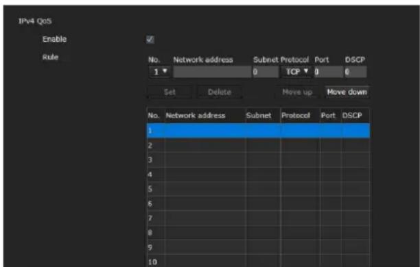
Use this menu to mark the data traffic packets sent from the device and configure the settings for QoS control. Rules for the types of data traffic can be created using IPv4 address, port number, protocol, etc. A maximum of 10 rules can be registered.
IPv4 QoS
Enable
Select the checkbox to configure the QoS setting for IPv4.
Rule
Used to register, edit and delete QoS.
No.
Select the number to use when registering on the QoS table.
When you select a registered number, the registered QoS information is displayed.
Network address
Enter the network address of the target on which to perform QoS.
Subnet
Enter the subnet mask values of the target on which to perform QoS.
Tip
The subnet mask value represents the number of bits from the left side of the network address.
Protocol
Select the protocol.
Port
Enter the port number for the data traffic of the device (e.g. HTTP: 80).
DSCP
Set a value to mark the data traffic (0 to 63).
This value is set in the DSCP field included in the IP header of the data traffic.
Set
Used when registering on the QoS table.
QoS is set according to the following procedure:
1 Select number for registration from [No.] and enter the necessary conditions for [Network address], [Subnet], [Protocol] and/or [Port].
2 Enter values in [DSCP].
3 Click [Set] and configure the QoS.
Delete
Select number from [No.] to delete the setting and click [Delete].
Move up
Increases the priority of the rule.
Select a rule from the QoS table to prioritize and click [Move up].
Move down
Decreases the priority of the rule.
Select a rule from the QoS table to lower its priority and click [Move down].
UPnP tab
Set UPnP (Universal Plug and Play).
Discovery
Enable
When this function is enabled, you can search the camera by using UPnP. Select the checkbox to use NDI|HX.
CNS tab (BRC-X400/X401)
The camera can be connected to an optional remote control panel (RCP) or master setup unit (MSU) for operation. For details about supported devices, contact your Sony sales representative.
Configure the following settings on the CNS tab to connect with an RCP/MSU.
Camera network system
Mode
[Bridge]: Set to Bridge mode to connect directly with an RCP on a LAN.
[MCS]: Set to MCS mode when building a multi-camera system on a LAN.
Master IP address
Set the IP address of the master device when building a multi-camera system on a LAN.
Camera No.
Set the camera number when building a multi-camera system on a LAN. Set so that the number is not duplicated within the system.
Notes
- Configure settings on the RCP/MSU side as required.
- An MSU is required in a multi-camera system.
- If there are multiple MSUs, set one MSU as the master, and set all other MSUs as clients.
Tracking data output tab (BRC-X400/X401)
The unit can output tracking data compliant with the free-d protocol from the LAN connector to work with various systems, such as virtual studio systems.
The tracking data is output using UDP packets in sync with the external sync signal.
Enable
Insert a check mark to enable the output of tracking data.
Destination IP address
When [Transfer mode] is set to [Always], specify the IP address of the client which will receive the tracking data from the camera.
UDP port number
When [Transfer mode] is set to [Always], specify the UDP port of the client which will receive the tracking data from the camera.
When [Transfer mode] is set to [On demand], specify the UDP port number on which the camera will listen for messages from the client.
Transfer mode
Set the output control method for the tracking data.
[Always]: Always output tracking data.
[On demand]: Start/stop output of tracking data in accordance with a "Type D0 (poll/command)" message from the client.
Camera ID
Set the ID for identifying the camera.
When [Transfer mode] is set to [On demand], the unit controls the output of tracking data using messages specified by Type D0 commands of the free-d protocol.
The unit supports the following commands.
00 (Stop stream mode): Stop output.
01 (Start stream mode): Start output.
In addition, the tracking data output from the unit is stored and output as shown below according to the format specified by the Type D1 command of the free-d protocol.
Camera ID: Stores the configured camera ID.
Camera Pan Angle: Stores the pan angle of the unit in a format specified by the free-d protocol.
Camera Tilt Angle: Stores the tilt angle of the unit in a format specified by the free-d protocol.
Camera Roll Angle: Not supported (always 0)
Camera X-Position: Not supported (always 0)
Camera Y-Position: Not supported (always 0)
Camera Height (Z-Position): Not supported (always 0)
Camera Zoom: Store the zoom position of the unit in the same format as VISCA commands.
Camera Focus: Store the focus position in the same format as VISCA commands.
Spare/Undefined Data: Stores the frame count from the upper 4 bits (0h to Fh) and the iris value (F value) of the unit from the lower 12 bits multiplied by 100.
Notes
- When mounted on a ceiling, set [IMG FLIP] in the SYSTEM menu to [ON] so that the Camera Pan Angle and Camera Tilt Angle data is in the correct orientation.
- The [TELE CONVERT MODE] magnification setting has no effect on the Camera Zoom value.
- If the tracking data is delayed or the value update falls behind, change to the following settings.
Do not use the streaming function.
Set a minimum value for [Frame rate 1] of [Image 1] in the Video codec tab.
Select [Off] for [Image 2]/[Image 3] Codec.
Clear the checkbox of [Image] in the Superimpose tab.
Clear the checkbox of [Enable] in the Audio tab.
Setting the Security — Security Menu
When you click security Administrator menu, the Security menu appears.
The Security menu consists of the [User], [Access limit], [SSL], [802.1X], [Referer check] and [Brute force attack protection] tabs.
Administrator and User
This camera identifies those who log in as the "Administrator" or "User".
The "Administrator" can use all the functions of this camera, including camera settings.
"User" can select user sections specified as available functions (access rights) in the [Viewer mode]. User section includes [Administrator] which can set all the functions as well as [Full] and [Light].
Each type of user can use the corresponding functions below.
| Function Administrator | User | |
| Full Light | ||
| Monitor a live image | ○ ○ ○ | |
| View the date and time | ○ ○ ○ | |
| Control the image view size | ○ ○ ○ | |
| Save a still image and movie in the computer | ○ ○ ○ | |
| Perform the pan/tilt/zoom/focus operation | ○ ○ - | |
| Receive audio ○ ○ | ○ | |
| Select the image on the monitor screen (Video 1 to 3) | ○ ○ ○ | |
| Perform the tally control | ○ ○ - | |
| Perform the streaming control (start/stop) | ○ ○ - | |
| Recalling the preset or PTZ trace | ○ ○ - | |
| Setting the preset or PTZ trace | ○ -- | |
| Control the setting menu | ○ -- | |
| Control the power ○ | -- | |
○ Usable function, – Not usable function
User tab
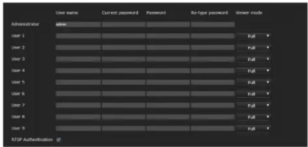
Set the user names and passwords of
Administrator and up to 9 types of user (User 1 to User 9), and the viewer mode of each user.
Enter your password in [Current password] when changing the user name and password or deleting the user.
When adding a new user, it is unnecessary to enter [Current password]. Enter a new user name in [User name] and enter a password in [Password] and [Re-type password].
Administrator
Specify [User name], [Current password], [Password], and [Re-type password] for each user ID.
User name
Enter a user name between 5 and 16 alphanumeric characters.
Current password
Enter the current password.
Password
Enter a password between 8 and 64 alphanumeric characters. Your password should be alphanumeric.
Re-type password
To confirm the password, retype the password that you entered in the [Password] box.
User 1 to 9
Specify [User name], [Current password], [Password], [Re-type password], and [Viewer mode] for each user ID.
User name
Enter a user name between 5 and 16 alphanumeric characters.
Current password
Enter the current password.
Password
Enter a password between 8 and 64 alphanumeric characters. Your password should be alphanumeric.
Re-type password
To confirm the password, retype the password that you entered in the [Password] box.
Viewer mode
You can select the viewer mode to be displayed after authentication when the viewer is displayed.
[Administrator]: The user can operate all functions including the setting menu in this mode.
[Full]: The user can operate all functions other than the setting menu and power.
[Light]: The user can select the image size and image (Video 1 to 3) of the live viewer.
Authentication
RTSP Authentication
Set whether the user is authenticated or not for RTSP streaming.
When the checkbox of [RTSP Authentication] is selected, user name and password specified in the User tab are authenticated.
Make sure to enter the correct user name and password to display the viewer.
As the One Shot JPEG image is displayed on the viewer when the codec is H.265, authentication is not performed.
Notes
- The RTSP authentication setting affects getting the RTSP streaming on programs other than a web browser. To prevent unspecified users from getting the streaming, select the checkbox of [RTSP Authentication] before use.
- When the setting is changed, RTSP streaming is temporarily interrupted. Therefore, while you display the viewer on another web browser, the screen turns black for a moment.
Access limit tab

This allows you to control which computers can have access to the camera.
Likewise, when using IPv6, security settings can be configured for each network.
Access limit
Set an access limit to the camera.
Enable
Select the checkbox to enable the access limit.
Rule
Set rules for the access limit of the camera.
Default policy
Select the basic policy of the limit from [Allow] and [Deny] for the computers with the network address that are not specified in the [Network address/Subnet 1] to [Network address/Subnet 10] menus below.
Network address/Subnet 1 to Network address/Subnet 10
Enter the network addresses and subnet mask values that you want to allow or deny access to the camera. You can specify up to 10 network addresses and subnet mask values.
For a subnet mask, enter 8 to 32.
(For IPv6, enter a value between 8 and 128.)
Select [Allow] or [Deny] from the drop-down list on the right for each network address/subnet mask.
Tip
The subnet mask value represents the number of bits from the left side of the network address.
For example, the subnet mask value for "255.255.255.0" is 24.
If you set "192.168.0.0/24" and [Allow], you can allow access from computers having an IP address between "192.168.0.0" and "192.168.0.255".
Note
You can access the camera even from a computer with an IP address whose access right is set to [Deny], if you enter the user name and password set for the Administrator in the User tab of the Security menu in the authentication screen.
SSL tab (BRC-X400, SRG-X400/X120)

Configure the SSL or TLS function (called "SSL" hereafter). The settings allow the camera to communicate with the client computer by using SSL.
Notes
- When using the SSL function, always configure the settings after setting the date and time of the camera. If the date and time are not correctly set, it may cause web browser connection problems.
- Reload the window when you change the SSL setting. Press the F5 key on the keyboard to reload.
SSL
Function
Select [Enable] to use the SSL function.
When [Enable (Allow HTTP connection for some clients)] is selected, both HTTP and SSL connections are allowed. When [Enable] is selected, only SSL connection is allowed.
When Internet Explorer is used
When SSL session is established, it appears in the right of the address bar on your web browser.
When you use SSL connection for the first time
When you use SSL connection only by setting the SSL function to [Enable], you cannot access the camera if the SSL function does not work properly. In this case, you must reset the camera to the factory settings. (All settings will be initialized.)
To avoid this, check that SSL connection is possible by performing the following steps.
1 Set the SSL function to [Enable (Allow HTTP connection for some clients)].
2 Click [OK] to close the web browser.
3 Display the viewer in SSL connection. For details, see "When the SSL Function is Used" (page 59).
4 After confirming that SSL connection is possible, set the SSL function to [Enable].
Even if the web browser is closed as SSL connection is impossible, HTTP connection will be possible if [Enable (Allow HTTP connection for some clients)] is selected. First check the setting contents of SSL tab in HTTP connection, then check the SSL connection again.
If [Enable (Allow HTTP connection for some clients)] is not selected, you will not be able to access the camera when SSL connection becomes impossible. In this case, press the reset switch on the camera for 5 seconds or longer to return to the factory default settings. For details, see page 9.
Note
SSL connection will load the camera down; therefore, not all images may be downloaded, and the mark may appear when the camera accesses from the web browser. In this case, reload the window. Press the F5 key on the keyboard to reload.
SSL server authentication
Certificate options
Select an installation mode of the certificate.
[Use an external certificate]: Uses the certificate including private key information issued by a CA. The PKCS#12 and PEM formats are supported.
Note
SSL is not available when [Certificate options]-[Use an external certificate] is selected, or certificate and private key password is not set properly even SSL is set to [Enable].
[Use a self-signed certificate (For test use)]: This mode uses the certificate and private key pair generated by "Self-signed certificate generation" (page 84). Private key information corresponding to the certificate is stored in the camera. You do not need to install an external certificate. However, you cannot execute the existence proof that is one of the SSL functions for the following reasons. - The private key generated in the camera is self-signed by the camera. - A prepared value is set for a distinguished name (Common name, etc). - The certificate is not issued by a trusted CA. For reasons of security, we recommend using this mode only when there is no problem even if perfect security is not ensured, such as for operation test.
Notes
- When [Use a self-signed certificate (For test use)] is selected, the [Security Alert] dialog appears on the SSL connection with a web browser. For details, see "When the SSL Function is Used" (page 59).
- SSL connection may be impossible due to the type of certificate installed in the camera. In this case, refer to "To import the CA certificate" on page 87 and install.
- When [Use a self-signed certificate (For test use)] is selected, you may not be able to use SSL connection depending on the web browser or OS you are using.
To import the certificate
Click [Choose File] to select the certificate to be imported. Follow the on-screen instructions to import the certificate to the camera.
Note
The import process becomes invalid if the selected file is not a certificate or the imported certificate is not allowed.
Self-signed certificate generation
A self-signed certificate can be generated in the camera to be used when [Use a self-signed certificate (For test use)] is selected from [Certificate options].
Click [Generate] to generate a self-signed certificate in the camera. Clicking [Generate] again after [Generate] has been clicked once will update the self-signed certificate stored in the camera.
Note
Make sure to set the date and time on the camera correctly before performing this operation. If the date and time are not correctly set, it may cause web browser connection problems. Before selecting [Generate] in [Self-signed certificate generation], click [OK] to select [Use a self-signed certificate (For test use)] in [Certificate options].
To display certificate information
When the certificate has been set in the camera correctly, its information appears on [Status], [Issuer DN], [Subject DN], [Available period] and [Extended key usage].
Status
Shows if the status of the certificate is valid or invalid. The following statuses are recognized.
[Valid]: The certificate is correctly stored and set.
[Invalid]: The certificate is not correctly stored and set.
Possible causes are as follows:
- [Use an external certificate] is selected and the private key password included in the certificate is not specified correctly.
- [Use an external certificate] is selected and the private key password is specified in spite of the fact that the key pair in the certificate is not encrypted.
- [Use an external certificate] is selected and the key pair is not included in the certificate.
- [Use a self-signed certificate (For test use)] is selected without the self-signed certificate being generated.
Note
When the certificate to be imported is of PKCS#12 format and the private key password is not set correctly, "
To delete the imported certificate or self-signed certificate
Click [Delete] to delete the certificate or self-signed certificate imported to the camera.
Private key password
Enter the password for the private key information included in the certificate using up to 50 characters. This text box is active only when [Certificate options] is set to [Use an external certificate].
Leave the text box blank if the private key information included in the certificate is not encrypted.
If no private key password is set in the camera, an active text field is displayed and this allows a password to be entered.
If a private key password is already set, it is displayed as an inactive text field.
Reset
To change the once set private key password, click [Reset] and clear the current password. A new password can be entered.
Note
Click [Cancel] at the bottom of the menu if you want to cancel changing the private key password after clicking [Reset]. Doing so restores the other setting items in the SSL tab to the previous settings.
802.1X tab

Configure the wired port-based authentication in compliance with the 802.1X standard.
Notes
- To use the 802.1X authentication function, you need knowledge of the 802.1X authentication and digital certificate. To establish an 802.1X network, you need to configure the authenticator, authentication server and other elements. For details on these settings, refer to the manual of the corresponding equipment.
- When using the 802.1X authentication function, always configure the settings after setting the date and time of the camera. If the date and time are incorrect, port authentication may not be performed correctly.
System configuration of the 802.1X network
The following figure shows a general system configuration of an 802.1X network.
![graph LR A["Supplicant (camera)"] --> B["Authenticator (hub or router)"] B --> C["Authentication server + CA"]](/content/2026/05/1130412/images/aa80e0f8481434e567036a935d19ab19a6dda3cfd7fbd4fbf73e2e366ca420a7.jpg)
Supplicant
A supplicant is a device that connects to the authentication server to join the network. This camera serves as a supplicant in the 802.1X network. The supplicant can enter the 802.1X network after appropriate authentication by the authentication server.
Authenticator
An authenticator forwards certificate request data or response data that the supplicant or authentication server issues to the other party. Normally a hub, router or access point serves as an authenticator.
Authentication server
An authentication server has a database of connecting users and verifies if the supplicant is a valid user or not. It can also be called RADIUS server.
CA (Certificate Authority)
A CA issues and manages certificates of the authentication server (CA certificates) and user certificates. The CA is essential for certificate-based user authentication. Normally a CA is located inside an authentication server.
Note
This camera supports EAP mode in which the supplicant and the server authenticate using the certificate. This mode requires a CA which issues the certificate.
802.1X
Enable
Select the checkbox to enable the 802.1X authentication function.
Setting
EAP identify
Enter the user name to identify the client in the 802.1X authentication server up to 250 characters.
EAP password
Enter a supplicant EAP password which is required when PEAP is selected with EAP mode. The password can be half-width letters and the length should be within 50 characters.
Reset
To change the once set EAP password, click [Reset] and clear the current password. A new password can be entered.
Note
Click [Cancel] at the bottom of the menu if you want to cancel changing the EAP password after clicking [Reset]. Doing so restores the other setting items to the previous settings.
EAP method
You can select the authentication method used with the authentication server. This camera supports TLS and PEAP.
[TLS]: By this method, the supplicant and the server authenticate each other using a certificate. This enables secure port authentication.
[PEAP]: By this method, an EAP password is used for the supplicant authentication and a certificate is used for server authentication.
Client certificate
When TLS is selected as the EAP method, the client certificate is imported, displayed or deleted for the camera authentication.
To import the client certificate
Click [Choose File] to select the client certificate to be imported. The selected client certificate is imported to the camera.
Note
The import process becomes invalid if the selected file is not a client certificate or the imported client certificate is not allowed.
To display client certificate information
When the client certificate has been set in the camera correctly, its information appears on [Status], [Issuer DN], [Subject DN], [Available period] and [Extended key usage].
Status
Shows if the status of the client certificate is valid or invalid. The following statuses are recognized.
[Valid]: The client certificate is correctly stored and set.
[Invalid]: The client certificate is not correctly stored and set. Possible causes are as follows:
- The private key password included in the client certificate is not specified correctly.
- The private key password is specified in spite of the fact that the key pair in the client certificate is not encrypted.
- The key pair is not included in the client certificate.
Note
When the client certificate to be imported is of PKCS#12 format and the private key password is not set correctly, "
To delete the client certificate
Click [Delete] to delete the client certificate stored in the camera.
Private key password
Enter the password for the private key information included in client certificate using up to 50 characters.
Leave the text box blank if the private key information included in the client certificate is not encrypted.
If a private key password is already set, it is displayed as turned letters.
Reset
To change the once set private key password, click [Reset] and clear the current password. A new password can be entered.
Note
Click a Ctrl bottom of the menu if you want to cancel changing the private key password after clicking [Reset]. Doing so restores the other setting items in the Client certificate tab to the previous settings.
Trusted CA certificate
You can import a trusted CA certificate (server certificate or route certificate) to the camera. Up to 4 certificates from trusted CAs can be imported. Only the PEM format is supported.
To import the CA certificate
Click [Choose File] to select the CA certificate to be imported. The selected CA certificate is imported to the camera.
Note
The import process becomes invalid if the selected file is not a CA certificate.
To display CA certificate information
When the CA certificate has been set in the camera correctly, its information appears on [Issuer DN], [Subject DN], [Available period] and [Extended key usage].
To delete the CA certificate
Click [Delete] to delete the CA certificate stored in the camera.
Referer check tab
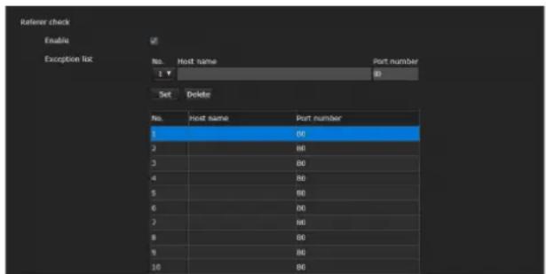
Referer check is the function that checks if the web page which requires access to the camera is authorized. If the web page is not authorized, the camera denies access of the web page. If you want to access from web pages other than the one that the camera provides, register their host names and port numbers in the [Exception list].
Referer check
Enable
Select the checkbox to enable the Referer check.
Exception list
Register the hosts that are not targeted for the Referer check.
No.
Select the registration number for the Exception list.
Host name
Enter the host name or IP address of the computer that supplies the web page you want to register on the Exception list.
Port number
Enter the port number of the computer that supplies the web page you want to register on the Exception list.
Set
Register the values of the [Host name] and [Port number] you entered to the list of the selected number.
Delete
Delete the contents of the list selected with [No.].
Brute force attack protection tab
Brute force attack means an attack method by trying every possible pattern of password in sequence. This camera has a function to prevent the Brute force attack.
- Applies to the HTTP and RTSP accesses.
- Does not monitor the Brute force attack to the RTSP access when the RTSP authentication is off.
Brute force attack protection
Enable
Select the checkbox to enable the Brute force attack protection function.
Setting
Make settings for the Brute force attack protection function.
Count
Set the number of count for the authentication failure of attacker detection.
Release mode
Set the mode to release attacker detection.
[Always]: Once registered in the attacker list, it will not be released.
[Timer]: Release after the time set in [Release time] has passed.
Note
The attacker list is released whenever the camera is rebooted even if the [Release mode] is in either case; [Always] and [Timer].
Release time
Set the time to release the attacker detection. This setting is available when the [Release mode] is set to [Timer].
Attacker list
Confirm the IP address of the user detected as an attacker.
Setting the PTZF Control — PTZF control Menu
When you click PTZF control administrator menu, the PTZF control menu appears. The PTZF control menu consists of the [PTZF control] and [Preset position] tab.
PTZF control tab
Perform the pan/tilt/zoom/focus operation. You can configure the settings from the OSD menu. For details, see "ZOOM/FOCUS Menu (BRC-X400/X401, SRG-X400/X402/201M2)" (page 40), "FOCUS Menu (SRG-X120/HD1M2)" (page 41), or "PAN TILT/PRESET RECALL Menu" (page 43).
Note
You cannot configure Focus near limit, PTZ mode, Pan-Tilt level, and Zoom level from the OSD menu.

Zoom (BRC-X400/X401, SRG-X400/X402/201M2)
Zoom mode (ZOOM - MODE)
Select the range of zooming.
[Optical]: An image can be zoomed up to 20× optical zoom.
[Clear Image Zoom]: An image is zoomed with less deterioration of image quality over the optical region. Zooming is up to 1.5× when the video output format is 3840×2160, and up to 2× for other formats.
[Digital]: An image can be zoomed up to 20× optical zoom and 12× digital zoom (including Clear Image Zoom) with up to a total of 240× zoom.
Focus
This is the setting related to the focus.
Focus mode (FOCUS - MODE)
Select the focus mode.
[Auto]: The focus is automatically adjusted.
[Manual]: The focus can be adjusted by using the

the control panel displayed in the main viewer.
Focus near limit
Set the range at which to automatically focus. If a subject is nearer than the set range, it will not be focused. The value is for reference.
Pan-Tilt
This is the setting related to the pan/tilt.
Pan-Tilt limit (PAN TILT - PAN LIMIT, TILT LIMIT)
Select the checkbox to limit the pan/tilt range. You can select the following values.
Note
Switching Image flip on/off turns Pan-Tilt limit setting to the factory setting. Set the Image flip function in accordance with the installation condition of the camera and select the value.
Left, Right (PAN TILT - LEFT, RIGHT)
Select the panning range.
[Left]: -170 degrees to +169 degrees, adjustable in 1 degree increment.
[Right]: -169 degrees to +170 degrees, adjustable in 1 degree increment.
Down, Up (PAN TILT - DOWN, UP)
Select the tilting range.
[Up]: -19 degrees to +90 degrees (Image flip: OFF) -89 degrees to +20 degrees (Image flip: ON), adjustable in 1 degree increment.
[Down]: -20 degrees to +89 degrees (Image flip: OFF)
-90 degrees to +19 degrees (Image flip: ON), adjustable in 1 degree increment.
Setting the range of the Up/Down movement
(Image flip: OFF)
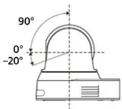
(Image flip: ON)
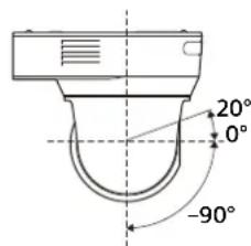
Ramp curve (PAN TILT - RAMP CURVE)
Set the acceleration/deceleration curve for pan/tilt.
Note
It is fixed to [Mode 1] on this camera.
Slow Pan-Tilt mode (PAN TILT - PAN TILT SLOW)
Select the checkbox to set [Pan-Tilt] to [Slow Pan-Tilt mode].
Preset
This is the setting related to the preset.
Speed select (PRESET RECALL - RECALL SPEED)
Select the preset recall speed.
[Compatible]: Work differently depending on the commands for preset recall. For VISCA command: Pan/tilt work with the speed set by each preset. For CGI command: Pan/tilt work with the speed specified by the CGI command of preset recall.
[Separate]: Pan/tilt work with the speed set by each preset.
[Common]: Pan/tilt work with the common speed to all presets.
Common speed (PRESET RECALL - COMMON SPEED)
This is enabled when [Speed select] is [Common]. Pan/tilt speed for preset recall, which is common to all presets.
Pict freeze preset (PRESET RECALL - PICT FREEZE PRESET)
Select output image state for preset recall. When the checkbox is selected, frozen images are output during preset recalling.
Preset mode (SYSTEM - PRESET MODE) (BRC-X400/X401)
Set preset mode.
[Mode 1]: Recall all saved settings when recalling a preset.
[Mode 2]: Recall only the pan, tilt, zoom, and focus positions when recalling a preset.
[Trace]: Function to record the pan/tilt/zoom operations to play them back when necessary.
PTZ mode
Set the pan/tilt control mode using the 8-direction arrow buttons (page 62) and the zoom control mode using the W / T buttons (page 62). Select [Normal] or [Step].
PTZ mode
[Normal]: When you click the mouse, the camera starts panning, tilting or zooming, and the operation continues while you hold down the mouse. To stop the operation, release the mouse.
[Step]: Each time you click the mouse, the camera moves (pans, tilts or zooms) according to the set level. If you keep the mouse held down for 1 second or more, the operation mode is temporarily changed to [Normal]. When you release the mouse, camera operation stops and the [Step] mode is restored.
When you select [Step], [Pan-Tilt level] and [Zoom level] are available.
Pan-Tilt level
Select the camera transition level from [1] to [10] by clicking the 8-direction arrow buttons for panning/tilting. Selecting [10] provides the maximum transition level.
Zoom level
Select the camera transition level from [1] to [10] by clicking /Wfor zooming. Selecting [10] provides the maximum transition level.
Preset position tab

You can store camera pan, tilt, and zoom positions up to 256 positions. For details on the camera settings that can be stored, see "Preset Items and Image Setting File Items" (page 98).
Notes
- All preset settings will return to their default when changing the setting of [Image flip] in the Installation tab.
Preset 1: The camera settings are reset to the default settings.
Preset 2 to 256: The camera settings are cleared from the memory.
Thumbnails are retained in the memory.
- The camera works with the setting registered to Preset 1, when the power of the camera is turned on. Register Preset 1 beforehand for turning on the camera with the specific settings.
- For BRC-X400/X401, when [Trace] is selected for [Preset mode] on the PTZF control tab, you cannot perform any operations on the Preset position tab. Select [Mode 1] or [Mode 2] for [Preset mode] on the PTZF control tab to perform operations.
Preset mode (BRC-X400/X401)
Display the current preset mode.
Preset position list
Display the numbers, names and thumbnails of the registered presets.
Select the preset to operate.
Preview screen
Monitor the images and perform the preset setting.
Set
Store the current pan, tilt, zoom positions and camera settings in the selected preset. For details on the setting items that can be stored, see "Preset Items and Image Setting File Items" (page 98).
Call
Move to the pan, tilt, and zoom positions stored in the selected preset. The stored camera settings are called. For BRC-X400/X401, you can select the setting items to be reflected on the camera by the Preset mode setting.
Add
Store the current pan, tilt, zoom positions and camera settings as a new preset. For details on the setting items that can be stored, see "Preset Items and Image Setting File Items" (page 98).
Remove
Delete the selected preset and return the stored settings to the factory settings. For details on the setting items stored in each preset, see "Preset Items and Image Setting File Items" (page 98).
Rename
Change the name of a selected preset. Up to 32 al phanumeric characters can be used to set the name.
Thumbnail (checkbox)
After selecting the checkbox, register the camera images as thumbnails by clicking [Set].
Thumbnail (file reference box)
Register the arbitrary camera images as thumbnails. Select images in JPEG or PNG format. The available image size is from 64×36 to 1920×1080 (width × height).
Delete
Delete thumbnails in the selected preset.
Speed
Pan/tilt speed when recalling the selected preset. This is available when [Speed select] is set to [Separate].
PTZ TRACE (BRC-X400/X401)
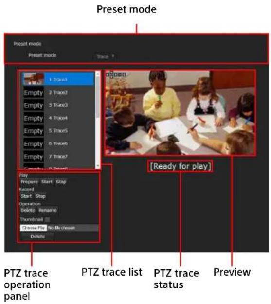
PTZ TRACE is a function used to record pan/tilt/zoom operations, controlled by the remote commander or a remote controller, and then to play back the operations when necessary. Up to 16 pan/tilt/zoom positions can be recorded for up to 180 seconds.
Notes
- If pan and tilt limits are configured in the PTZ control tab after recording operations, the pan and tilt limits are not applied during playback. To use the PTZ trace function and pan/tilt limit function together, first configure the pan/tilt limit settings, and then use the PTZ trace function.
- All recorded PTZ traces will be erased if the image flip setting is changed.
- All recorded PTZ traces may be erased if the video output format is changed.
- Playing preparation will restore the Zoom mode and Slow Pan-Tilt mode to their states held during recording.
Preset mode
Display the current preset mode.
PTZ trace list

Display the PTZ trace number, PTZ trace name, and thumbnail. "Empty" is displayed for the thumbnail of the unrecorded PTZ trace.
Select the PTZ trace you want to play back.
Preview
Monitor the images and perform the preset settings.
PTZ trace status
Display the operation status of the PTZ trace function under the preview screen. [Ready for play], [Playing], or [Recording] is displayed as the status.
PTZ trace operation panel
Perform playback, recording, operations, or setting thumbnail of the selected PTZ trace.
Play

Prepare
Prepare to play back the selected PTZ trace. The camera moves the position to the recorded pan/tilt/zoom start position.
Start
Start playing back the PTZ trace which has been prepared.
Stop
Stop playing back the PTZ trace.
Note
Playback stops if you perform pan/tilt/zoom operations while playback is in progress.
Record

Start
Start recording on the selected PTZ trace number. Perform pan/tilt/zoom operations to record.
Recording stops when the recording time reaches its maximum time.
Stop
Stop PTZ trace recording.
Operation
Delete
Delete pan/tilt/zoom operations recorded on the selected PTZ trace number.
Rename
Change the name of the selected PTZ trace number. Up to 32 alphanumeric characters can be used to set the name.
Thumbnail
Thumbnail (Checkbox)
Register the camera images when the recording is started as thumbnails when PTZ trace recording is started with the Thumbnail checkbox selected.
Thumbnail (File reference box)
Register the arbitrary camera images as thumbnails. Select images in JPEG or PNG format. The available image size is from 64×36 to 1920×1080 (width × height).
Delete
Delete thumbnails in the selected PTZ trace.
Setting the Streaming — Streaming Menu
When you click Streaming Administrator menu, the Streaming menu appears.
Use this menu to select the streaming mode and its setting.
The Streaming menu consists of the [Streaming] tab.
Streaming tab
Note
When Streaming tab settings are changed, RTSP streaming is temporarily interrupted. Therefore, while you display the viewer on another web browser, the screen turns black for a moment.
Streaming mode
When the audio setting is enabled, select the streaming mode from [RTSP], [RTMP], [SRT-Caller], [SRT-Listener], and [Off]. When the audio setting is not enabled, select it from [RTSP] and [Off].
The setting items are displayed according to the selected mode.
When selecting [RTSP]
Unicast streaming
RTSP video port number [1 to 3]
Specify the video transmission port number used for RTSP unicast streaming. The default setting is 51000, 53000 or 55000. Specify an even number from [1024] to [65534]. 2 port numbers (the number specified here and an odd number with 1 added to the specified number) are actually used for video data communication and control. When performing simultaneous multi-transmission, a different port number will be used for every transmission, based on the port number specified here.
The settings for Image 1, Image 2 and Image 3 apply to RTSP video port number 1, 2 and 3 respectively.
RTSP audio port number
Specify the audio transmission port number used for RTSP unicast streaming. The default setting is 57000. Specify an even number from [1024] to [65534]. 2 port numbers (the number specified here and an odd number with 1 added to the specified number) are actually used for audio data communication and control. When performing simultaneous multi-transmission, a different port number will be used for every transmission, based on the port number specified here.
Multicast streaming
Set whether the camera uses multicast streaming with video data and audio data or not. It reduces the transmission load on the camera by having a computer of the same segment network receive the same transmitting data.
Enable
Select the checkbox to allow multicast streaming. When you have selected the checkbox, set [Multicast address], [Video port number], and [Audio port number] properly.
Multicast TTL
Set the TTL (Time To Live) for the multicast packet. Adjust the value when you want to perform the multicast across the router.
Multicast address
Set the multicast address used on the RTSP multicast streaming.
Video port number [1 to 3]
Specify the video transmission port number used for RTSP multicast streaming. The default setting is 61000, 63000 or 65000. Specify an even number from [1024] to [65534]. 2 port numbers (the number specified here and an odd number with 1 added to the specified number) are actually used for video data communication and control. The settings for Image 1, Image 2 and Image 3 apply to video port number 1, 2 and 3 respectively.
Audio port number
Specify the audio transmission port number used for RTSP multicast streaming. The default setting is 59000. Specify an even number from [1024] to [65534]. 2 port numbers (the number specified here and an odd number with 1 added to the specified number) are actually used for audio data communication and control.
RTSP setting
Set the RTSP setting which cannot be set in the Unicast streaming setting and Multicast streaming.
RTSP port number
Set the port number used for RTSP streaming. The default setting is 554. If you change the setting, the RTSP server will be rebooted.
RTSP time out
Specify the time for the time out by the Keep-Alive command from RTSP streaming. You can set the time out from [0] second to [600] seconds. At the [0] setting, time out of the Keep-Alive command is not available.
RTSP streaming authentication can be enabled/disabled from RTSP Authentication (page 82) on the User tab.
Examples of RTSP streaming acquisition
This camera is compatible with RTSP as the streaming protocol. Up to three streams are available for the camera. The URL of each stream is as follows.
- rtsp://
/video1 (Image 1) - rtsp://
/video2 (Image 2) - rtsp://
/video3 (Image 3) : RTSP port number
Note
Playing on media players other than web browsers is not guaranteed.
When selecting [RTMP]
RTMP setting
Perform settings related to RTMP streaming.
Server URL
Set the URL for the upload. Specify a string starting with "rtmp://" or "rtmps://."
Stream key
Enter a stream key acquired from the site to be used.
Note
Be careful when handling the stream key. If the stream key is known by a third party, there may be a risk of spoofed streaming.
Reset
Clear the text box of the stream key.
CA certificate
Import a CA certificate that is required when streamed with the RTMPS protocol. Click the [Browse] button to import a CA certificate, and then select a CA certificate. Click the [OK] button in the file selection dialog to import the selected file into the unit. If the imported CA certificate is already in the unit, it will be updated. Click the [Delete] button in the configuration screen to delete the imported certificate.
Notes
- Import the CA certificate necessary for the streaming service.
- The models for China do not support the RTMPS protocol. Therefore, the import certificate function is not available for Chinese models.
When selecting [SRT-Caller] or [SRT-Listener]
SRT setting
Perform settings related to SRT streaming.
Destination
When the streaming mode is [SRT-Caller], set the destination URL.
Port number
When the streaming mode is [SRT-Listener], set the port number for listening.
Latency
Set the delay amount from [20] ms to [8000] ms.
TTL
Set the TTL value from [1] to [255].
Encryption
Select the encryption method from [Off], [AES128], or [AES256].
Passphrase
Set the passphrase used for encryption.
ARC
Select the checkbox to enable the adaptive rate control function.
When the adaptive rate control function is enabled, it is possible to reduce the image interruption caused by congestion of the communication line.
Note
The models for China do not support encryption and passphrase.
Using NDI|HX
To use NDI|HX, you are required to purchase the license key.
Purchasing the license key
You can purchase the license key from the following URL of NewTek, Inc. http://new.tk/ndi_sony
Notes
- Download the latest driver of NDI|HX and install it in NewTek products.
- For details on settings and operations for NDI|HX, refer to the instructions of NewTek products.
Services and software provided by other companies
- Separate terms and conditions of use may be applied.
- Provision of services and software updates may be interrupted or terminated without notice.
• Services and software content are subject to change without notice. - Separate registration and/or payment may be required.
Please note that Sony Corporation is not responsible for any claim, from customers or third parties, arising from any use of services and software provided by other companies.
Message List
The following messages and indications may appear on this camera. Perform the following as necessary.
Camera Lamp Display
| Lamp status Description and solution | |
| POWER lamp (orange) and NETWORK lamp (green) are flashing. | An error has occurred in the camera. Details of the error are displayed in the main menu. Check the details of the error before solving the problem. |
Camera Screen Display (Main Menu)
| Message Description and solution | |
| ⚠ FAN STOP! | Turn off the device as it may malfunction if used in this state. Contact the Sony Service Center or your licensed Sony dealer. |
| ⚠ PAN-TILT ERROR! | The movement of the camera has stopped due to an error in the pan-tilt driving unit. Reset the pan/tilt position. Or, turn off and on the camera. |
| ⚠ PAN-TILT FAULT! | Turn off the device as it may malfunction if used in this state. Contact the Sony Service Center or your licensed Sony dealer. |
| ⚠ MEMORY FAULT! | The memory of the camera has been damaged. The camera is running on an older version. Turn off the camera and contact the Sony Service Center or your licensed Sony dealer. |
List of error codes for RTMP streaming
The error codes displayed on this unit are as follows. If necessary, take the following actions.
| Error Codes Description Remedy | |||
| RTMP RTMPS | |||
| 1002 | 2002 | Unable to connect to RTMP server Check if the Server URL setting is correct. | |
| 1004 | 2004 | Check the network connection. | |
| 1003 | 2003 | Unable to resolve domain name | Check if the Server URL setting is correct. Check if the DNS Server setting is correct. |
| - 2005 | 2008 | CRL error | Check if the Server URL setting is correct. Check if the destination is a trusted site. |
| - | 2006 | CA certificate error | Check if the time setting is correct. Check if the CA certificate is correct. |
| - | 2007 Not | installed CA certificate. Server certificate validation error. | Install a CA certificate. Check if the destination is a trusted site. |
| 4002 | Disconnected RTMP Session. | It may be disconnected from the RTMP server side. Check if it matches the recommended codec parameters of the service. | |
| 4003 | Poor network line quality. | Check the network connection. | |
| others | Any other error. | ||
List of error codes for SRT streaming
The error codes displayed on this unit are as follows. If necessary, take the following actions.
| Error Codes Description | tion Remedy | ||
| SRT-Caller SRT-Listener | |||
| 1001 | Unexpected error | The unit may not operate properly. Turn off and on the unit. | |
| 1002 Disconnection of communication due to setting change | The communication has been disconnected because the configuration was changed. Connect to communicate again. | ||
| 5001 | Unexpected error | The unit may not operate properly. Turn off and on the unit. | |
| 5002 Unexpected error | |||
| 5003 Unexpected error | |||
| 5004 Unexpected error | |||
| 5005 | Connection failed | Check if the destination setting is correct. | |
| 5006 | Encryption error | Check if the encryption setting is correct. | |
| 5007 | Unexpected error | The unit may not operate properly. Turn off and on the unit. | |
| 5008 Unexpected error | |||
| 5009 | Sending failed | Disconnection occurred during communication. Check the network connection. | |
Troubleshooting
Before sending your camera for service, check the following to troubleshoot the problem. If the problem still persists, consult the Sony Service Center.
| Symptom Cause Remedy | ||
| The power of the camera is not turned on. | The AC adapter is not firmly connected to the DC IN 12 V terminal. | Firmly insert the AC adapter all the way. |
| The power cord is not firmly connected to the AC adapter or the power supply. | Firmly insert the power cord all the way. | |
| The connection cable to the PoE+ power supply device is not firmly connected. | Firmly insert the connection cable all the way. | |
| A non-PoE+ compliant-power supply device is connected. | Connect a PoE+ compliant-power supply device. | |
| The camera does not work, even when buttons on the remote commander are pressed. | [IR RECEIVE] on the SYSTEM menu is turned [OFF], or the [IR receive] checkbox on the Administrator menu is cleared. | Set [IR RECEIVE] to [ON] by operating the menu with the remote controller RM-IP500/IP10 (page 46), or select the [IR receive] checkbox from the Administrator menu on the web browser (page 66). |
| The remote commander's CAMERA SELECT button number and the camera's IR SELECT switch setting are different. | Press the CAMERA SELECT button that matches the IR SELECT switch setting (page 11). | |
| The OSD menu is not displayed. | The [Menu overlay (SDI)] or [Menu overlay (HDMI)] check box on the Administrator menu is not selected. | Select the checkbox of the item corresponding with video output to display the OSD menu. |
| An image is not displayed on the connected video monitor. | The video connecting cable is not connected properly. | Check the connection between the camera and video monitor. |
| Exposure settings on the camera are not appropriate. | Check the exposure settings in the EXPOSURE menu. | |
| Pan, tilt, or zoom cannot be operated. | The camera OSD menu is displayed. Close the menu by pressing the DATA SCREEN button on the supplied remote commander. Or close the menu with the remote controller. | |
| The camera cannot be operated with the remote controller RM-IP500/IP10. | The connection method is not configured properly. | Configuration of the connection method (VISCA RS-422 or VISCA over IP) for RM-IP500/IP10 is required. Check whether the connection method for RM-IP500/IP10 corresponds to the connected cable. |
| The VISCA RS-422 connection is incorrect. | Check the connection to the VISCA RS-422 terminal and the wiring of the RS-422 cable. | |
| Communication baud rate settings are different. | Set the same settings for the baud rate (9600 bps or 38400 bps) of the remote controller and the CAMERA SETUP switch (page 9) on the back of the camera. | |
| The VISCA over IP connection is incorrect. | Check the connection to the LAN terminal. Use a cross network cable when connected to the remote controller on a one-to-one basis. | |
| VISCA is not available even when the camera is connected to a computer. | The computer is not correctly connected to the camera. | Check the connection between the camera and computer. |
| Make sure that the baud rate (9600 bps or 38400 bps) is correctly set on the CAMERA SETUP switch on the back of the camera (page 9) and set in the computer settings. | ||
| Connect the camera to the remote controller RM-IP500/IP10 to check whether the camera is not damaged. | ||
| Cannot access the camera or acquire streaming using a Web browser. | The HTTP/RTSP function is set to [OFF]. | Select [ON] for the SYSTEM - HTTP/RTSP setting on the OSD menu. Alternatively, select [FORCED ON] for the HTTP/RTSP communication usage setting with the CAMERA SETUP switch (page 9) on the back of the camera. |
| Symptom Cause | Remedy |
| Problems are not resolved although measures were taken. | — Remove the plug of the power cord from the AC outlet, then reinsert it into the AC outlet after waiting a while. |
Preset Items and Image Setting File Items
Items stored in the preset and image setting file are shown in the following lists.
Item stored in the preset
●: Stores settings by preset.
○: Applies the settings to the camera at the next start-up when they are stored in Preset 1. Preset recall does not apply the settings.
Item stored in the image setting file
O: Stored
-: Not stored
The preset mode can be set in BRC-X400/X401. You can select setting items to be applied to the camera in the preset mode setting when recalling a preset.
[Mode 1]: Pan/tilt/zoom/focus settings and camera settings
[Mode 2]: Only Pan/tilt/zoom/focus settings
Pan/tilt/zoom/focus settings and camera settings are applied in SRG-X400/X402/201M2/X120/HD1M2.
Pan/Tilt/Zoom/Focus Settings
| Item name on the OSD menu | Item name on the Administrator menu | Items other than the OSD/Administrator menu | Item stored in the preset | Item stored in the image setting file |
| -- Pan-Tilt position | ● - | |||
| RAMP CURVE Ramp curve - | ○ - | |||
| PAN TILT SLOW Slow Pan-Tilt mode - | ○ - | |||
| PAN LIMIT, TILT LIMIT Pan-Tilt limit - | ○ - | |||
| PRESET MODE Preset mode - | O*1 | - | ||
| - Name (Preset position list) - | ○ - | |||
| - | Thumbnail (Preset position list) | - | ○ - | |
| PRESET RECALL SPEED | Speed select | - | ○ - | |
| PRESET RECALL COMMON SPEED | Common speed | - | ○ - | |
| - Speed (Preset position list) - | ● - | |||
| ZOOM MODE | Zoom mode | - | ● - | |
| -- Zoom position | ● - | |||
| TELE CONVERT MODE | Tele convert | - | O*2 | - |
| FOCUS MODE | Focus mode | - | ● - | |
| -- Focus position | ● - | |||
| -- Auto focus mode | ○ - | |||
| -- Auto focus interval | ○ - | |||
| -- Auto focus sensitivity | ● - | |||
| - Focus near limit | - | ● - |
*1 The BRC-X400/X401 only
*2 The BRC-X400/X401 and SRG-X402 only
Camera Settings
| Item name on the OSD menu | Item name on the Administrator menu | Items other than the OSD/Administrator menu | Item stored in the preset | Item stored in the image setting file |
| EXPOSURE MODE Mode (Exposure) - | ● | ○ | ||
| IRIS Iris - | ● | ○ | ||
| GAIN Gain - | ● | ○ | ||
| GAIN LIMIT Auto gain Max. value - | ● | ○ | ||
| GAIN POINT Gain point - | ● | ○ | ||
| GAIN POINT LEVEL Gain point level - | ● | ○ | ||
| - | - | High-sensitivity Mode | ● | ○ |
| SHUTTER SPEED | Shutter speed | - | ● | ○ |
| MAX SHUTTER SPEED | Fastest (Shutter speed) | - | ● | ○ |
| MIN SHUTTER SPEED | Slowest (Shutter speed) | - | ● | ○ |
| SLOW SHUTTER On/Off | Auto slow shutter | - | ● | ○ |
| EX-COMP On/Off | - | - | ● | - |
| EX-COMP LEVEL | Exposure compensation | - | ● | ○ |
| BACKLIGHT | Backlight compensation | - | ● | ○ |
| SPOTLIGHT | Spotlight compensation | - | ● | ○ |
| AE SPEED | AE speed | - | ● | ○ |
| - | - | AE Ref. Low-light Modulation On/Off | ● | ○ |
| - | - | AE Ref. Low-light Modulation Level | ● | ○ |
| VISIBILITY ENHANCER On/Off | Visibility Enhancer (On/Off) | - | ● | ○ |
| VISIBILITY ENHANCER EFFECT | Visibility Enhancer (Effect) | - | ● | ○ |
| WHITE BALANCE MODE | Mode (White balance) | - | ● | ○ |
| WHITE BALANCE MODE SPEED | Speed (White balance) | - | ● | ○ |
| WHITE BALANCE MODE OFFSET | Offset (White balance) | - | ● | ○ |
| WHITE BALANCE MANUAL R-GAIN | R Gain (White balance) | - | ● | ○ |
| WHITE BALANCE MANUAL B-GAIN | B Gain (White balance) | - | ● | ○ |
| - | - | R-Gain of OnePushWB | ● | - |
| - | - | B-Gain of OnePushWB | ● | - |
| COLOR MATRIX On/Off | Color matrix-Enable (On/Off) | - | ●*1 | ○*1 |
| COLOR MATRIX SELECT | Matrix | - | ●*1 | ○*1 |
| COLOR LEVEL | Saturation | - | ●*1 | ○*1 |
| COLOR PHASE | Hue | - | ●*1 | ○*1 |
| R-G R-G | - | ●*1 | ○*1 | |
| R-B | R-B | - | ●*1 | ○*1 |
| G-R G-R | - | ●*1 | ○*1 | |
| G-B G-B | - | ●*1 | ○*1 | |
| B-R | B-R | - | ●*1 | ○*1 |
| B-G B-G | - | ●*1 | ○*1 | |
| GAMMA SELECT | Gamma | - | ●*1 | ○*1 |
| GAMMA PATTERN | Pattern (Gamma) | - | ●*1 | ○*1 |
| GAMMA OFFSET | Offset (Gamma) | - | ●*1 | ○*1 |
| GAMMA LEVEL Level (Gamma) - | ●*1 | ○*1 | ||
| BLACK GAMMA Black gamma level - | ●*1 | ○*1 | ||
| BLACK GAMMA RANGE Black gamma range - | ●*1 | ○*1 | ||
| BLACK LEVEL Black level - | ●*1 | ○*1 | ||
| KNEE SETTING On/Off Knee setting (On/Off) - | ●*1 | ○*1 | ||
| KNEE MODE Knee mode - | ●*1 | ○*1 | ||
| KNEE SLOPE Knee slope - | ●*1 | ○*1 | ||
| KNEE POINT Knee point - | ●*1 | ○*1 | ||
| DETAIL MODE | Mode (Detail) | - | ● | ○ |
| DETAIL LEVEL | Level (Detail) | - | ● | ○ |
| DETAIL BAND WIDTH | Bandwidth (Detail) | - | ● | ○ |
| DETAIL CRISPENING | Crispening (Detail) | - | ● | ○ |
| DETAIL HV BALANCE | HV balance (Detail) | - | ● | ○ |
| DETAIL BW BALANCE | BW balance (Detail) | - | ● | ○ |
| DETAIL LIMIT | Limit (Detail) | - | ● | ○ |
| HIGHLIGHT DETAIL | Highlight detail | - | ● | ○ |
| DETAIL SUPER LOW | Detail Super low | - | ● | ○ |
| - | - | Low Illumination Color NR | ● | ○ |
| - | - | Defog | ● | ○ |
| FLICKER CANCEL On/Off | Flicker cancel (On/Off) | - | ● | ○ |
| HIGH RESOLUTION | High resolution mode (On/Off) | - | ● | ○ |
| IMAGE STABILIZER | Image stabilizer (On/Off) | - | ● | ○ |
| NOISE REDUCTION | NR mode | - | ● | ○ |
| - | NR (XDNR) - | ● | ○ | |
| 2D NR LEVEL | 2D level | - | ● | ○ |
| 3D NR LEVEL | 3D level | - | ● | ○ |
| - | - | Picture Effect | ● | - |
| IR CUT FILTER | Mode (Day/Night ICR) | - | ● | - |
| ICR THRESHOLD | Threshold | - | ● | - |
| IR RECEIVE | IR receive | - | ○ | - |
| TALLY LEVEL | Tally level | - | ○*1 | - |
| H PHASE | - | - | ○*1 | - |
| HDMI COLOR SPACE | Color space | - | ○ | - |
*1 The BRC-X400/X401 only
Specifications
System
Video signal 3840 × 2160/29.97p * 1
1920 × 1080/59.94p
1920 × 1080/59.94i
1920 × 1080/29.97p
1280 × 720/59.94p
3840 × 2160/25p *1
1920 × 1080/50p
1920 × 1080/50i
1920 x 1080/25p
1280 × 720/50p
3840 × 2160/23.98p * 1
1920 × 1080/23.98p
*1 SDI input is not supported.
Details of each model (page 104)
Synchronization
Internal synchronization/External synchronization, Automatic switching (BRC-X400/X401)
Internal synchronization (SRG-X400/X402/201M2/X120/HD1M2)
Image device 1/2.5-type, CMOS image sensor
Effective pixel number: Approx. 8.5 Megapixels
Camera
Lens Optical, 20 ×
f = 4.4 mm to 88.0 mm, F2.0 to F3.8
f = 26.8 mm to 536.0 mm (35 mm camera conversion) (BRC-X400/X401, SRG-X400/X402/201M2)
Optical, 12 x
f=4.4 mm to 52.8 mm, F2.0 to F3.7
f = 26.8 mm to 322.8 mm (35 mm camera conversion) (SRG-X120/HD1M2)
Minimum object distance
80 mm (WIDE), 800 mm (Tele) (BRC-X400/X401, SRG-X400/X402/201M2)
80 mm (WIDE), 400 mm (Tele) (SRG-X120/HD1M2)
Minimum illumination
1.6 lux 4K/HD output, 50IRE, F2.0, 1/30s, High-sensitivity Mode: OFF
Max.Gain (WIDE end)
Shutter speed
1/10000s to 1/1s
Pan/Tilt function
Horizontal ±170 degrees
Maximum speed: 101 degrees/second
Minimum speed: 0.5 degrees/second
Maximum speed (when the
preset is recalled): 300
degrees/second
Minimum speed (when the
preset is recalled): 1.1 degrees/second
Vertical +90 degrees, -20 degrees
Maximum speed: 91 degrees/second
Minimum speed: 0.5 degrees/second
Maximum speed (when the preset is recalled): 126 degrees/second
Minimum speed (when the preset is recalled): 1.1 degrees/second
Output terminals
HDMI OUT Terminal: HDMI connector (Type A) × 1
Standards: Version 1.4b compatible
Color space: YCbCr, 4:2:2 8bit RGB, 4:4:4 8bit
SDI OUT Terminal: BNC connector × 1
Standards: 3G-SDI
Input and Output terminals
VISCA RS-422 Terminal: RJ45 × 2
Standards: VISCA
LAN terminal Terminal: RJ45
Standards: IEEE802.3at compatible (PoE+)
Input terminals
EXT SYNC IN Terminal: BNC connector × 1 (BRC-X400/X401)
MIC Terminal: Mini jack ∅ 3.5 (×2) (Plug in Power supported)
Power terminal
IEC60130-10 (JEITA standard RC-5320A) TYPE 4
General
Input voltage DC 12 V (AC adapter 100 to 240 V, 50/60 Hz), PoE+ (IEEE802.3at compatible)
Power consumption
For DC 12 V: 23.8 W
For PoE+: 25.5 W
Operating temperature
0° C to 40° C (32°F to 104°F)
Storage temperature
-20°C to +60°C (-4°F to +140°F)
External dimensions (Dimensions page 103)
158.4 × 177.5 × 200.2 mm
(61/4×7×8 inches)
(width/height/depth) (without
protrusions)
Mass Approx. 1.8 kg (3 lb 16 oz)
Installation angle
Less than ±15 degrees to the
horizontal surface
Supplied Accessories
Safety Regulations (1)
AC adapter (1)
Remote commander (1)
Ceiling bracket (A) (1)
Ceiling bracket (B) (1)
Wire rope (1)
Mounting screws (⊕M3×8) (9)
Mounting screws (⊕M2.6×6 black) (1)
HDMI cable fixing plate (1)
Optional accessories
Remote controller (RM-IP500/IP10)
Design and specifications are subject to change without notice.
Dimensions
Top

Front

Side

Bottom

Ceiling bracket (B)

Unit: mm (inches)
SYSTEM SELECT switch settings
Video output format for the HDMI OUT/SDI OUT terminal can be set with this switch.
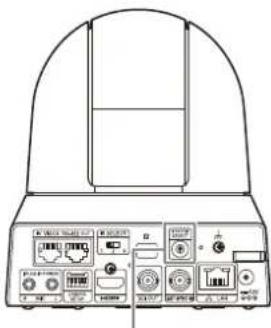

| No. Video output format/Frame rate | ||
| BRC-X400/X401 and SRG-X400/ X402/201M2/ X120/HD1M2 (with 4K Option)* 2 | SRG-X400/X402/ 201M2/X120/ HD1M2 (without 4K Option)* 2 | |
| 0 384 | 0x2160/29.97p 1920x1080/59.94p | |
| 1 1920 | 0x1080/59.94p 1920x1080/59.94p | |
| 2 1920 | 0x1080/59.94i 1920x1080/59.94i | |
| 3 1920 | 0x1080/29.97p 1920x1080/29.97p | |
| 4 | 1280x720/59.94p | 1280x720/59.94p |
| 5 1920 | 0x1080/59.94p 1920x1080/59.94p | |
| 6 | REMOTE *1 | REMOTE *1 |
| 7 HDMI : 640x480/ 59.94p SDI : 1280x720/ 59.94p | HDMI : 640x480/ 59.94p SDI : 1280x720/ 59.94p | |
| 8 384 | 0x2160/25p 1920x1080/59.94p | |
| 9 1920 | 0x1080/50p 1920x1080/50p | |
| A 1920 | 0x1080/50i 1920x1080/50i | |
| B 1920 | 0x720/50p 1920x720/50p | |
| C 1280 | 0x720/50p 1280x720/50p | |
| D 1920 | 0x1080/59.94p 1920x1080/59.94p | |
| E 384 | 0x2160/23.98p 1920x1080/59.94p | |
| F 1920 | 0x1080/23.98p 1920x1080/23.98p | |
*1 You can change the setting from the OSD menu, Administrator menu, or VISCA/CGI command with Software version 2.00 or later.
*2 4K Option can be installed with Software version 2.00 or later. You need to purchase the license key to install 4K Option.
Notes
- Be sure to set the switch before you turn on the camera.
Turn on the power after you set the switch. - Be sure to use a Phillips-head screwdriver when changing the switch position. If you use a tool other than the designated screwdriver, the crossed groove may be damaged.
Pin array of the VISCA RS-422 terminal and how to use it
Pin array of VISCA RS-422 terminal

IN
| Pin No. | Function |
| 1 | TX- |
| 2 | TX+ |
| 3 | RX- |
| 4 | GND |
| 5 | GND |
| 6 | RX+ |
| 7 | N.C. |
| 8 | N.C. |

OUT
| Pin No. | Function |
| 1 | RX- |
| 2 | RX+ |
| 3 | TX- |
| 4 | GND |
| 5 | GND |
| 6 | TX+ |
| 7 | N.C. |
| 8 | N.C. |
Connection diagram with remote controller RM-IP10
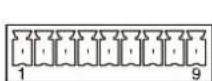

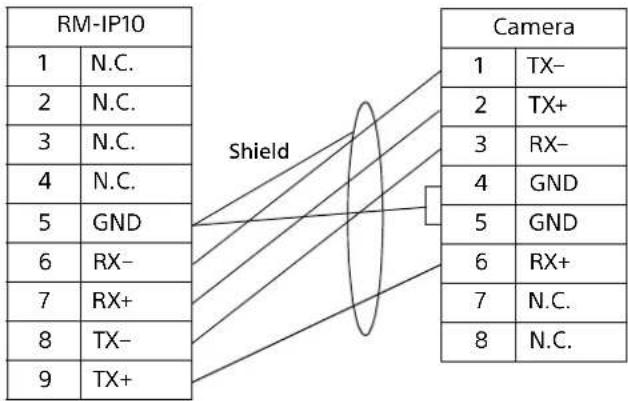
Notes
- Connect the GNDs of both devices together to stabilize the voltage level of the signal.
- When preparing cables, use network cables of category 5e or more and equivalent to or higher than shielded twisted pair cables.


- TABLE OF CONTENTS
- OVERVIEW
- LOCATION AND FUNCTION OF PARTS
- SYSTEM CONFIGURATION
- INSTALLATION AND CONNECTION
- OPERATIONS USING THE SUPPLIED INFRARED REMOTE COMMANDER
- ADJUSTING AND CONFIGURING THE CAMERA THROUGH ON-SCREEN MENUS
- ACCESSING THE CAMERA FROM A WEB BROWSER
- OPERATING THE CAMERA FROM A WEB BROWSER
- CONFIGURING THE CAMERA FROM A WEB BROWSER
- SETTING THE PTZF CONTROL
- SETTING THE STREAMING
- APPENDIX
- SAFETY REGULATIONS (SUPPLIED)
- OPERATING INSTRUCTIONS (THIS DOCUMENT/WEB)
- USING THIS MANUAL
- JUMPING TO A RELATED PAGE
- SOFTWARE DISPLAY EXAMPLES
- PRINTING THE OPERATING INSTRUCTIONS
- ABOUT THE DESCRIPTION IN THIS DOCUMENT
- PRECAUTIONS FOR PREVENTING ACCESS TO THE CAMERA BY AN UNINTENDED THIRD PARTY
- FEATURES
- PAN/TILT/ZOOM CMOS VIDEO CAMERA EQUIPPED WITH A SMALL BUILT-IN PAN-TILT HEAD
- ZOOM PERFORMANCE FOR CAPTURING DISTANT SUBJECTS
- AUDIO OUTPUT
- VIDEO OUTPUT
- PRESET FUNCTION
- EQUIPPED WITH RS-422 INTERFACE
- EQUIPPED WITH POE+ (POWER OVER ETHERNET PLUS)
- COMPATIBLE WITH VISCA OVER IP PROTOCOL
- EQUIPPED WITH EXTERNAL VIDEO SYNC FUNCTION (BRC-X400/X401)
- EQUIPPED WITH TALLY LAMP (BRC-X400/X401)
- SUPPORTS NETWORK CONNECTION WITH RCP/MSU (BRC-X400/X401)
- PICTURE PROFILE PRESET FUNCTION (BRC-X400/X401)
- EXTENSIBILITY
- CAMERA
- 1 TALLY LAMP (BRC-X400/X401)
- 2 LENS
- NOTE
- 3 REMOTE COMMANDER SENSORS
- 4 POWER LAMP
- 5 NETWORK LAMP
- 6 VSCA RS-422 IN TERMINAL
- 7 VISCA RS-422 OUT TERMINAL
- 8 IRSELECT SWITCH
- 9 REMOTE COMMANDER SENSOR
- 10 SYSTEM SELECT SWITCH
- 11 RESET SWITCH
- 12 (EARTH) TERMINAL
- 13 AC ADAPTER CORD CLAMPER
- 14 MIC TERMINAL (AUDIO INPUT TERMINAL)
- 15 CAMERA SETUP SWITCHES
- ① SDI FORMAT/LEVEL SETTINGS
- 16 HDMI OUT TERMINAL
- 17 SDI OUT TERMINAL
- 18 EXT SYNC IN (ONLY BRC-X400/X401)
- 19 LAN (NETWORK) TERMINAL (RJ-45)
- FACTORY SETTINGS FOR NETWORK
- 20 --- 12 V ◇C◆ (DC POWER INPUT) TERMINAL
- 21 CEILING BRACKET MOUNTING SCREW HOLES
- 22 TIPOD SOCKET HOLE
- 23 RATING LABEL
- IMPORTANT
- INFRARED REMOTE COMMANDER (SUPPLIED)
- 1 CAMERA SELECT BUTTONS
- 2 FOCUS BUTTONS
- 3 DATA SCREEN BUTTON
- NOTES
- 4 PAN-TILT BUTTON
- 5 VR DIRECTION SET BUTTON
- 6 POWER BUTTON
- 7 BACK LIGHT BUTTON
- 8 POSITION BUTTONS
- 9 AN-TILT RESET BUTTON
- 10 ZOOM BUTTONS
- REQUIRED BATTERIES
- OPERATING A SINGLE CAMERA USING THE SUPPLIED REMOTE COMMANDER
- OPERATING A SINGLE CAMERA USING THE OPTIONAL REMOTE CONTROLLER
- OPERATING MULTIPLE CAMERAS USING THE OPTIONAL REMOTE CONTROLLER
- WHAT YOU CAN DO WITH THIS SYSTEM
- INSTALLING THE CAMERA
- INSTALLING THE CAMERA ON A DESK
- ATTACHING THE CAMERA TO A TRIPOD
- CAUTION
- INSTALLING THE CAMERA USING THE M3 FIXING SCREW HOLES
- INSTALLING THE CAMERA ON THE CEILING
- BEFORE INSTALLING THE CAMERA
- HOW TO INSTALL THE CAMERA
- 1 ATTACH THE WIRE ROPE TO THE CEILING
- IN THE CASE THAT A WIRE CANNOT BE ATTACHED ON THE CEILING, ATTACH THE WIRE ON THE CEILING BRACKET (B) AS ILLUSTRATED BELOW WITH THE SUPPLIED SCREWS (M3×8)
- WARNING
- 3 ATTACH THE CEILING BRACKET (A) TO THE BOTTOM OF THE CAMERA USING THE 4 SCREWS (M 3 × 8) SUPPLIED
- 7 ADJUST THE IMAGE FLIP FUNCTION TO OPTIMIZE THE CEILING MOUNTING STATUS
- HOW TO REMOVE THE CAMERA
- CONNECTING THE CAMERA
- CONNECTING TO AN AC POWER SUPPLY
- CONNECTING THE CAMERA TO A POE+ (POWER OVER ETHERNET PLUS) POWER SUPPLY DEVICE
- CONNECTING A SINGLE CAMERA TO A SWITCHER, RECORDER, OR MONITOR
- CONNECTING A SINGLE CAMERA TO A SINGLE REMOTE CONTROLLER (NOT SUPPLIED)
- CONNECTING A SINGLE CAMERA TO A REMOTE CONTROLLER DIRECTLY
- USING THE VISCA RS-422 TERMINAL
- CONNECTING MULTIPLE CAMERAS TO A SINGLE REMOTE CONTROLLER (NOT SUPPLIED)
- CONNECTING MULTIPLE CAMERAS USING VISCA OVER IP
- CONNECTING A COMMERCIALLY AVAILABLE VIDEO SWITCHER
- FOR 4K OUTPUT (HDMI OUTPUT ONLY)
- FOR HD OUTPUT
- EXTERNAL SYNCHRONIZATION (BRC-X400/X401)
- FOR A SINGLE CAMERA
- FOR MULTIPLE CAMERAS
- CONNECTING TO COMMERCIALLY-AVAILABLE MICROPHONES ETC
- BEFORE STARTING OPERATIONS
- TURNING ON THE POWER
- OPERATING MULTIPLE CAMERAS USING THE INFRARED REMOTE COMMANDER
- PAN/TILT OPERATION
- 1 PRESS THE POWER BUTTON
- 2 PRESS AN ARROW BUTTON TO PAN OR TILT THE CAMERA
- TO FACE THE CAMERA BACK TO THE FRONT
- IF YOU ACCIDENTALLY MOVE THE CAMERA WITH YOUR HAND
- WHEN THE CAMERA MOVES IN A DIFFERENT DIRECTION FROM WHAT YOU INTENDED
- IF THE POWER LAMP AND NETWORK LAMP ON THE CAMERA FLASH SIMULTANEOUSLY, AND "PAN-TILT ERROR!" IS DISPLAYED ON THE MENU SCREEN
- ZOOM OPERATION
- ADJUSTING THE CAMERA
- FOCUSING ON A SUBJECT
- TO ADJUST THE FOCUS AUTOMATICALLY
- TO ADJUST THE FOCUS MANUALLY
- SHOOTING WITH BACK LIGHTING
- STORING THE CAMERA SETTINGS IN MEMORY– PRESET FEATURE
- RECALLING THE STORED STATUS
- CLEARING THE PRESET MEMORY
- STORING CAMERA PAN/TILT AND ZOOM OPERATIONS
- PTZ TRACE FUNCTION (BRC-X400/X401)
- RECORDING PAN/TILT AND ZOOM OPERATIONS
- PLAYING PAN/TILT AND ZOOM OPERATIONS
- DELETING RECORDED PAN/TILT AND ZOOM OPERATIONS
- OPERATING MENUS
- DISPLAYING A MENU
- RETURNING TO THE MAIN MENU
- CANCELING A MENU
- ABOUT ON-SCREEN MENUS
- CONFIRMING SELECTION OF MENU ITEMS AND SETTINGS/EXECUTING OPERATIONS
- MAIN MENU
- ① CUSOR
- ② MENU ITEMS
- ③ 6NTROL BUTTON DISPLAY SECTION
- SETTING MENU
- 1 SETTING MENU
- ② CURSOR
- ③ SETTING ITEMS
- 4 SE VALUE
- ⑤ CONTROL BUTTON DISPLAY SECTION
- STATUS
- EXPOSURE MENU
- MODE (EXPOSURE - MODE)
- GAIN (EXPOSURE - GAIN)
- SPEED (EXPOSURE - SHUTTER SPEED)
- WHEN THE SIGNAL FORMAT IS 59.94 OR 29.97
- WHEN THE SIGNAL FORMAT IS 50 OR 25
- WHEN THE SIGNAL FORMAT IS 23.98
- IRIS (EXPOSURE - IRIS)
- AE SPEED (EXPOSURE - AE SPEED)
- EX-COMP (EXPOSURE - EXPOSURE COMPENSATION)
- LEVEL (EXPOSURE - EXPOSURE COMPENSATION)
- GAIN LIMIT (EXPOSURE - AUTO GAIN MAX. VALUE)
- GAIN POINT (EXPOSURE - GAIN POINT)
- POINT POSITION (EXPOSURE - GAIN POINT LEVEL)
- MAX SPEED (EXPOSURE - FASTEST)
- MIN SPEED (EXPOSURE - SLOWEST)
- BACKLIGHT (EXPOSURE - BACKLIGHT COMPENSATION)
- SPOTLIGHT (EXPOSURE - SPOTLIGHT COMPENSATION)
- SLOW SHUTTER (EXPOSURE - AUTO SLOW SHUTTER)
- COLOR MENU
- WHITE BALANCE MODE (WHITE BALANCE - MODE)
- SPEED (WHITE BALANCE - SPEED)
- OFFSET (WHITE BALANCE - OFFSET)
- R.GAIN (WHITE BALANCE - R GAIN) B.GAIN (WHITE BALANCE - B GAIN)
- MATRIX (COLOR MATRIX - ENABLE) (BRC-X400/X401)
- SELECT (COLOR MATRIX - MATRIX) (BRC-X400/X401)
- LEVEL (COLOR MATRIX - SATURATION) (BRC-X400/X401)
- PHASE (COLOR MATRIX - HUE) (BRC-X400/X401)
- R-G, R-B, G-R, G-B, B-R, B-G (COLOR MATRIX - R-G, R-B, G-R, G-B, B-R, B-G) (BRC-X400/X401)
- DETAIL MENU
- MODE (DETAIL - MODE)
- LEVEL (DETAIL - LEVEL)
- BAND WIDTH (DETAIL - BANDWIDTH)
- CRISPENING (DETAIL - CRISPENING)
- HV BALANCE (DETAIL - HV BALANCE)
- BW BALANCE (DETAIL - BW BALANCE)
- LIMIT (DETAIL - LIMIT)
- HIGHLIGHT DETAIL (DETAIL - HIGHLIGHT DETAIL)
- SUPER LOW (DETAIL - SUPER LOW)
- KNEE MENU (BRC-X400/X401)
- SETTING (KNEE - KNEE SETTING)
- KNEE MODE (KNEE - KNEE MODE)
- KNEE SLOPE (KNEE - KNEE SLOPE)
- KNEE POINT (KNEE - KNEE POINT)
- GAMMA/VISIBILITY ENHANCER MENU (BRC-X400/X401)
- GAMMA
- SELECT (GAMMA - GAMMA)
- PATTERN (GAMMA - PATTERN)
- PATTERN FINE
- OFFSET (GAMMA - OFFSET)
- LEVEL (GAMMA - LEVEL)
- BLACK GAMMA (GAMMA - BLACK GAMMA LEVEL)
- BLACK GAMMA RANGE (GAMMA - BLACK GAMMA RANGE)
- BLACK LEVEL (GAMMA - BLACK LEVEL)
- VISIBILITY ENHANCER
- SETTING (EXPOSURE - VISIBILITY ENHANCER)
- EFFECT (EXPOSURE - EFFECT)
- VISIBILITY ENHANCER MENU (SRG-X400/X402/201M2/X120/HD1M2)
- ZOOM/FOCUS MENU (BRC-X400/X401, SRG-X400/X402/201M2)
- ZOOM
- MODE (ZOOM - ZOOM MODE)
- FOCUS
- MODE (FOCUS - FOCUS MODE)
- FOCUS MENU (SRG-X120/HD1M2)
- PICTURE/OPTICAL FILTER MENU
- PICTURE
- HIGH RESOLUTION (PICTURE - HIGH RESOLUTION MODE)
- NOISE REDUCTION (PICTURE - NR MODE)
- 2D NR LEVEL (PICTURE - 2D NR LEVEL)
- 3D NR LEVEL (PICTURE - 3D NR LEVEL)
- FLICKER CANCEL (PICTURE - FLICKER CANCEL)
- IMAGE STABILIZER (PICTURE - IMAGE STABILIZER)
- OPTICAL FILTER
- IR CUT FILTER (DAY/NIGHT ICR - MODE)
- ICR THRESHOLD (DAY/NIGHT ICR - SWITCHING LEVEL)
- PAN TILT/PRESET RECALL MENU
- PAN TILT
- PAN LIMIT (PAN-TILT - PAN LIMIT)
- LEFT (PAN-TILT - LEFT)
- RIGHT (PAN-TILT - RIGHT)
- TILT LIMIT (PAN-TILT - TILT LIMIT)
- DOWN (PAN-TILT - DOWN)
- UP (PAN-TILT - UP)
- RAMP CURVE (PAN-TILT - RAMP CURVE)
- PAN TILT SLOW (PAN-TILT - SLOW PAN-TILT MODE)
- PRESET RECALL
- RECALL SPEED (PRESET - SPEED SELECT)
- COMMON SPEED (PRESET - COMMON SPEED)
- PICT FREEZE PRESET (PRESET - PICT FREEZE PRESET)
- PICTURE PROFILE MENU (BRC-X400/X401)
- PROFILE NUMBER
- RECALL: EXECUTE
- VIDEO OUT MENU
- HDMI
- COLOR SPACE (VIDEO OUT - COLOR SPACE)
- H PHASE (BRC-X400/X401)
- H PHASE
- H PHASE FINE
- SYSTEM MENU
- IMG FLIP (SYSTEM - IMAGE FLIP)
- IR RECEIVE (SYSTEM - IR RECEIVE)
- TALLY LEVEL (SYSTEM - TALLY LEVEL) (BRC-X400/X401)
- TELE CONVERT MODE (SYSTEM - TELE CONVERT) (BRC-X400/X401, SRG-X402)
- HTTP/RTSP
- PRESET MODE (PRESET - PRESET MODE) (BRC-X400/X401)
- STANDBY MODE (SYSTEM - STANDBY MODE)
- COLOR BAR OVERLAY NAME (BRC-X400/X401)
- VIDEO FORMAT (SYSTEM - VIDEO OUTPUT)
- REBOOT
- PTZ TRACE MENU (BRC-X400/X401)
- STATUS MENU
- FOR BRC-X400/X401
- FOR SRG-X400/X402/201M2
- FOR SRG-X120/HD1M2
- DEVICE INFO (DEVICE INFORMATION OF THE CAMERA AND SETTING STATUS OF SWITCHES ON THE BACK OF THE CAMERA)
- MODEL NAME (INFORMATION - MODEL NAME)
- SERIAL NUMBER (INFORMATION - SERIAL NUMBER)
- VERSION (INFORMATION - SOFTWARE VERSION)
- NAME (COMMON SETTING - CAMERA NAME)
- SYSTEM MODE (VIDEO OUT - FORMAT)
- IR SELECT
- SDI LEVEL
- VISCA RATE
- 4K OPTION (OPTION - 4K OPTION) (SRG-X400/X402/201M2/SRG-X120/HD1M2)
- NETWORK
- MAC ADDRESS (STATUS - MAC ADDRESS)
- IP ADDRESS (STATUS - IP ADDRESS)
- SUBNET MASK (STATUS - SUBNET MASK)
- GATEWAY (STATUS - DEFAULT GATEWAY)
- MENU CONFIGURATION
- ENABLING HTTP/RTSP IN THE CAMERA
- SETTING-UP THE COMPUTER
- OS/WEB BROWSER
- CPU
- MEMORY
- DISPLAY
- CHANGING THE INITIAL PASSWORD
- DISPLAYING THE VIEWER SCREEN PROPERLY
- WHEN YOU USE ANTIVIRUS SOFTWARE ON YOUR COMPUTER
- WHEN THE SSL FUNCTION IS USED
- WHEN INTERNET EXPLORER IS USED
- WHEN [ENABLE (ALLOW HTTP CONNECTION FOR SOME CLIENTS)] (PAGE 83) IS SELECTED
- FOR HTTP CONNECTION
- FOR SSL CONNECTION
- ABOUT AUTHENTICATION
- OPERATING THE CAMERA
- LIVE
- SETTING
- LICENSE NOTICE
- LANGUAGE
- STANDBY / ON
- CONTROL PANEL SECTION
- INFORMATION PANEL
- CURRENT DATE & TIME
- VIEW PANEL
- SCREEN MODE
- VIEW SIZE
- IMAGE CODEC
- STILL IMAGE CAPTURE
- START STORING VIDEO/ STOP STORING VIDEO
- VOLUME CONTROL
- CAMERA PANEL
- PAN/TILT CONTROL
- ZOOM CONTROL
- FOCUS CONTROL
- TALLY LAMP CONTROL
- STREAMING PANEL
- MODE
- PRESET POSITION PANEL
- PRESET CONTROL
- PTZ TRACE PANEL (BRC-X400/X401)
- PTZ TRACE CONTROL
- MONITOR SCREEN
- NOTE ON THE DISPLAY OF MENU OPTIONS
- BASIC OPERATIONS OF THE ADMINISTRATOR MENU
- HOW TO SET UP THE ADMINISTRATOR MENU
- COMMON BUTTONS IN EACH MENU
- OK
- CANCEL
- RELOAD
- NOTES FOR ALL ASPECTS OF THE MENU
- CONFIGURATION OF THE ADMINISTRATOR MENU
- VIDEO MENU
- AUDIO MENU
- NETWORK MENU
- SECURITY MENU
- PTZF CONTROL MENU
- STREAMING MENU
- CONFIGURING THE SYSTEM — SYSTEM MENU
- INFORMATION TAB
- INFORMATION
- DATE & TIME TAB
- DATE & TIME
- PC CLOCK
- DATE & TIME FORMAT
- TIME SETTING
- NTP AUTO
- NTP SERVER
- NTP INTERVAL
- TIME ZONE
- AUTOMATICALLY ADJUST CLOCK FOR DAYLIGHT SAVING TIME CHANGES
- INSTALLATION TAB
- SYSTEM
- IMAGE FLIP (SYSTEM - IMG FLIP)
- TELE CONVERT (SYSTEM - TELE CONVERT MODE) (BRC-X400/X401, SRG-X402)
- MENU OVERLAY (SDI)
- MENU OVERLAY (HDMI)
- VIDEO OUT
- FORMAT (DEVICE INFO - SYSTEM MODE)
- INITIALIZE TAB
- INITIALIZE
- FACTORY DEFAULT
- RETAIN CURRENT NETWORK SETTINGS
- TIP
- DELETE SUPERIMPOSE LOGO
- EXPORT/IMPORT
- EXPORT SETTING FILE
- IMPORT SETTING FILE
- VERSION UP
- FIRMWARE UPGRADE
- SYSTEM LOG TAB
- SYSTEM LOG
- LOG LEVEL
- LOG SIZE
- DOWNLOAD AS FILE
- ACCESS LOG TAB
- ACCESS LOG
- SERVICE TAB
- CONSENT
- I AGREE TO DOWNLOAD DEVICE INFORMATION
- DEVICE INFORMATION
- OPTION TAB (SRG-X400/X402/201M2/X120/HD1M2)
- DEVICE UNIQUE ID
- 4K OPTION
- LICENSE FILE
- TO ENABLE THE OPTIONAL FUNCTION BY PURCHASING A LICENSE
- SETTING THE CAMERA IMAGE — VIDEO MENU
- PICTURE TAB
- EXPORT/IMPORT (PICTURE SETTING FILE)
- EXPORT PICTURE SETTING FILE
- IMPORT PICTURE SETTING FILE
- KEEP CURRENT PICTURE SETTINGS AFTER REBOOT
- SAVE TO PRESET 1
- EXPOSURE
- VISIBILITY ENHANCER (VISIBILITY ENHANCER - SETTING)
- EFFECT (VISIBILITY ENHANCER - EFFECT)
- AUTO GAIN MAX. VALUE (EXPOSURE - GAIN LIMIT)
- GAIN POINT LEVEL (EXPOSURE - POINT POSITION)
- SHUTTER SPEED (EXPOSURE - SPEED)
- FASTEST (EXPOSURE - MAX SPEED)
- SLOWEST (EXPOSURE - MIN SPEED)
- AUTO SLOW SHUTTER (EXPOSURE - SLOW SHUTTER)
- EXPOSURE COMPENSATION (EXPOSURE - EX-COMP, LEVEL)
- BACKLIGHT COMPENSATION (EXPOSURE - BACKLIGHT)
- SPOTLIGHT COMPENSATION (EXPOSURE - SPOTLIGHT)
- WHITE BALANCE
- MODE (COLOR - WHITE BALANCE MODE)
- SPEED (COLOR - SPEED)
- OFFSET (COLOR - OFFSET)
- ONE PUSH TRIGGER (COLOR - ONE PUSH TRIGGER)
- R GAIN (COLOR - R.GAIN)
- B GAIN (COLOR - B.GAIN)
- COLOR MATRIX (BRC-X400/X401)
- ENABLE (COLOR - MATRIX)
- MATRIX (COLOR - SELECT)
- SATURATION (COLOR - LEVEL)
- HUE (COLOR - PHASE)
- R-G, R-B, G-R, G-B, B-R, B-G (COLOR - R-G, R-B, G-R, G-B, B-R, B-G)
- DETAIL
- BANDWIDTH (DETAIL - BAND WIDTH)
- GAMMA (BRC-X400/X401)
- GAMMA (GAMMA - SELECT)
- BLACK GAMMA LEVEL (GAMMA - BLACK GAMMA)
- KNEE (BRC-X400/X401)
- KNEE SETTING (KNEE - SETTING)
- HIGH RESOLUTION MODE (PICTURE - HIGH RESOLUTION)
- NR MODE (PICTURE - NOISE REDUCTION)
- NR (XDNR)
- VIDEO CODEC TAB
- IMAGE 1, IMAGE 2, IMAGE 3
- CODEC
- SIZE
- FRAME RATE
- I-PICTURE MODE
- I-PICTURE INTERVAL
- I-PICTURE RATIO
- H264 PROFILE
- BIT RATE COMPRESSION MODE
- BIT RATE
- H264 QUALITY
- H265 QUALITY
- SUPERIMPOSE TAB
- IMAGE
- POSITION
- TYPE
- CUSTOM STRING
- TEXT COLOR
- BACKGROUND COLOR
- ALIGNMENT
- TRANSPARENT
- FONT SIZE
- FILE SELECT
- DAY/NIGHT ICR TAB
- DAY/NIGHT ICR
- MODE (OPTICAL FILTER - IR CUT FILTER)
- THRESHOLD (OPTICAL FILTER - ICR THRESHOLD)
- NEAR-IR CORRECTION
- SETTING THE AUDIO — AUDIO MENU
- AUDIO TAB
- INPUT SELECTION
- MIC VOLUME
- AUDIO LEVEL CONTROL
- EQUALIZER
- SEND
- ENABLE
- AUDIO CODEC
- CONFIGURING THE NETWORK — NETWORK MENU
- ETHERNET STATUS
- SECONDARY DNS SERVER
- IPV6 ADDRESS 1
- IPV6 ADDRESS 2
- IPV6 DEFAULT GATEWAY
- LINKLOCAL IPV6 ADDRESS
- IPV4 SETTING
- OBTAIN AN IP ADDRESS AUTOMATICALLY (DHCP)
- IP ADDRESS
- SUBNET MASK
- DEFAULT GATEWAY
- IPV6 SETTING
- OBTAIN AN IP ADDRESS AUTOMATICALLY
- PREFIX LENGTH
- COMMON SETTING
- HTTP PORT NUMBER
- OBTAIN DNS SERVER ADDRESS AUTOMATICALLY
- PRIMARY DNS SERVER
- CAMERA NAME (DEVICE INFO - NAME)
- IPV4 QOS
- RULE
- NO
- NETWORK ADDRESS
- SUBNET
- PROTOCOL
- PORT
- DSCP
- SET
- DELETE
- MOVE UP
- MOVE DOWN
- UPNP TAB
- DISCOVERY
- CNS TAB (BRC-X400/X401)
- CAMERA NETWORK SYSTEM
- MASTER IP ADDRESS
- CAMERA NO
- TRACKING DATA OUTPUT TAB (BRC-X400/X401)
- DESTINATION IP ADDRESS
- UDP PORT NUMBER
- TRANSFER MODE
- CAMERA ID
- SETTING THE SECURITY — SECURITY MENU
- ADMINISTRATOR AND USER
- USER TAB
- ADMINISTRATOR
- USER NAME
- CURRENT PASSWORD
- PASSWORD
- RE-TYPE PASSWORD
- USER 1 TO 9
- VIEWER MODE
- AUTHENTICATION
- RTSP AUTHENTICATION
- ACCESS LIMIT TAB
- ACCESS LIMIT
- DEFAULT POLICY
- NETWORK ADDRESS/SUBNET 1 TO NETWORK ADDRESS/SUBNET 10
- SSL TAB (BRC-X400, SRG-X400/X120)
- SSL
- FUNCTION
- WHEN YOU USE SSL CONNECTION FOR THE FIRST TIME
- SSL SERVER AUTHENTICATION
- CERTIFICATE OPTIONS
- TO IMPORT THE CERTIFICATE
- SELF-SIGNED CERTIFICATE GENERATION
- TO DISPLAY CERTIFICATE INFORMATION
- TO DELETE THE IMPORTED CERTIFICATE OR SELF-SIGNED CERTIFICATE
- PRIVATE KEY PASSWORD
- RESET
- 802.1X TAB
- SYSTEM CONFIGURATION OF THE 802.1X NETWORK
- SUPPLICANT
- AUTHENTICATOR
- AUTHENTICATION SERVER
- CA (CERTIFICATE AUTHORITY)
- 802.1X
- EAP IDENTIFY
- EAP PASSWORD
- EAP METHOD
- CLIENT CERTIFICATE
- TO IMPORT THE CLIENT CERTIFICATE
- TO DISPLAY CLIENT CERTIFICATE INFORMATION
- TO DELETE THE CLIENT CERTIFICATE
- TRUSTED CA CERTIFICATE
- TO IMPORT THE CA CERTIFICATE
- TO DISPLAY CA CERTIFICATE INFORMATION
- TO DELETE THE CA CERTIFICATE
- REFERER CHECK
- EXCEPTION LIST
- HOST NAME
- PORT NUMBER
- BRUTE FORCE ATTACK PROTECTION TAB
- BRUTE FORCE ATTACK PROTECTION
- COUNT
- RELEASE MODE
- RELEASE TIME
- ATTACKER LIST
- SETTING THE PTZF CONTROL — PTZF CONTROL MENU
- PTZF CONTROL TAB
- ZOOM (BRC-X400/X401, SRG-X400/X402/201M2)
- FOCUS MODE (FOCUS - MODE)
- FOCUS NEAR LIMIT
- PAN-TILT
- PAN-TILT LIMIT (PAN TILT - PAN LIMIT, TILT LIMIT)
- LEFT, RIGHT (PAN TILT - LEFT, RIGHT)
- DOWN, UP (PAN TILT - DOWN, UP)
- SETTING THE RANGE OF THE UP/DOWN MOVEMENT
- RAMP CURVE (PAN TILT - RAMP CURVE)
- SLOW PAN-TILT MODE (PAN TILT - PAN TILT SLOW)
- PRESET
- SPEED SELECT (PRESET RECALL - RECALL SPEED)
- COMMON SPEED (PRESET RECALL - COMMON SPEED)
- PICT FREEZE PRESET (PRESET RECALL - PICT FREEZE PRESET)
- PRESET MODE (SYSTEM - PRESET MODE) (BRC-X400/X401)
- PTZ MODE
- PAN-TILT LEVEL
- ZOOM LEVEL
- PRESET POSITION TAB
- PRESET MODE (BRC-X400/X401)
- PRESET POSITION LIST
- PREVIEW SCREEN
- CALL
- ADD
- REMOVE
- RENAME
- THUMBNAIL (CHECKBOX)
- THUMBNAIL (FILE REFERENCE BOX)
- SPEED
- PTZ TRACE (BRC-X400/X401)
- PRESET MODE
- PTZ TRACE LIST
- PREVIEW
- PTZ TRACE STATUS
- PTZ TRACE OPERATION PANEL
- PLAY
- PREPARE
- START
- STOP
- RECORD
- OPERATION
- THUMBNAIL
- SETTING THE STREAMING — STREAMING MENU
- STREAMING TAB
- STREAMING MODE
- WHEN SELECTING [RTSP]
- UNICAST STREAMING
- RTSP VIDEO PORT NUMBER [1 TO 3]
- RTSP AUDIO PORT NUMBER
- MULTICAST STREAMING
- MULTICAST TTL
- MULTICAST ADDRESS
- VIDEO PORT NUMBER [1 TO 3]
- AUDIO PORT NUMBER
- RTSP SETTING
- RTSP PORT NUMBER
- RTSP TIME OUT
- EXAMPLES OF RTSP STREAMING ACQUISITION
- WHEN SELECTING [RTMP]
- RTMP SETTING
- SERVER URL
- STREAM KEY
- CA CERTIFICATE
- WHEN SELECTING [SRT-CALLER] OR [SRT-LISTENER]
- SRT SETTING
- DESTINATION
- LATENCY
- TTL
- ENCRYPTION
- PASSPHRASE
- ARC
- USING NDI|HX
- PURCHASING THE LICENSE KEY
- SERVICES AND SOFTWARE PROVIDED BY OTHER COMPANIES
- MESSAGE LIST
- LIST OF ERROR CODES FOR RTMP STREAMING
- LIST OF ERROR CODES FOR SRT STREAMING
- TROUBLESHOOTING
- PRESET ITEMS AND IMAGE SETTING FILE ITEMS
- ITEM STORED IN THE PRESET
- ITEM STORED IN THE IMAGE SETTING FILE
- SPECIFICATIONS
- OUTPUT TERMINALS
- INPUT AND OUTPUT TERMINALS
- INPUT TERMINALS
- GENERAL
- SUPPLIED ACCESSORIES
- OPTIONAL ACCESSORIES
- DIMENSIONS
- SYSTEM SELECT SWITCH SETTINGS
- PIN ARRAY OF THE VISCA RS-422 TERMINAL AND HOW TO USE IT
- PIN ARRAY OF VISCA RS-422 TERMINAL
- CONNECTION DIAGRAM WITH REMOTE CONTROLLER RM-IP10
Brand : SONY
Model : SRG-X400UH
Category : Security Camera