
M 12SA2 - Saw HiKOKI - Free user manual and instructions
Find the device manual for free M 12SA2 HiKOKI in PDF.


| Product Type | Router (Woodworking Router) |
| Brand | HiKOKI (formerly Hitachi) |
| Model | M12SA2 |
| Power Input | 1700 W (depending on region: 110V/120V/220V/230V/240V) |
| Collet Chuck Capacity | 12 mm or 1/2" |
| No-Load Speed | 22000 min⁻¹ (fixed speed) |
| Stroke (Max Plunge Depth) | 65 mm |
| Weight (without cord and standard accessories) | 6.2 kg |
| Depth Adjustment | Quick adjustment lever and fine adjustment knob with scale and stopper block for up to 3 preset depths |
| Guide Systems | Template guide adapter, template guide, straight guide with bar holder and feed screw, dust guide and dust guide adapter |
| Standard Accessories | Straight guide (1), bar holder (1), guide bars (2), feed screw (1), wing bolts, dust guide, dust guide adapter, template guide, template guide adapter, centering gauge, knob, wrench, 8mm collet chuck, lock spring |
| Optional Accessories | Additional template guides (various sizes), chuck sleeves, trimmer guide, template guide adapter (B) |
| Applications | Grooving, chamfering, edge profiling, template work on wood |
| Safety Features | Lock pin for arbor, double insulation, safety warnings in manual, lock lever for depth adjustment |
| Maintenance | Oil sliding portions occasionally; carbon brush inspection/replacement only by authorized service center |
| Noise & Vibration | Sound power level 97 dB(A), sound pressure level 84 dB(A), vibration 1.3 m/s² (K=3 dB) |
Frequently Asked Questions - M 12SA2 HiKOKI
User questions about M 12SA2 HiKOKI
0 question about this device. Answer the ones you know or ask your own.
Ask a new question about this device
Download the instructions for your Saw in PDF format for free! Find your manual M 12SA2 - HiKOKI and take your electronic device back in hand. On this page are published all the documents necessary for the use of your device. M 12SA2 by HiKOKI.
USER MANUAL M 12SA2 HiKOKI
natural_image
Technical line drawing of a mechanical device with springs and housing (no text or symbols)M12V2
Read through carefully and understand these instructions before use.
2
3
4

natural_image
Mechanical assembly diagram showing hands operating a piston and crankshaft (no text or labels)5

6
7

natural_image
Mechanical assembly diagram showing a hand adjusting components with a numbered label (16), no readable text or symbols present.8
9

10

natural_image
Line drawing of hands operating a machine with a clover symbol on the wall (no text or symbols present)11

12

13

14
natural_image
Line drawing of hands operating a mechanical device with no visible text or symbols15

16
natural_image
Technical line drawing of a mechanical component with a numbered annotation (36), no readable text or symbols present.
flowchart
graph TD
    A["Step 40"] --> B["Step 41"]
    B --> C["Step 42"]
    C --> D["Step 40"]
    style A fill:#f9f,stroke:#333
    style B fill:#ccf,stroke:#333
    style C fill:#cfc,stroke:#333
    style D fill:#fcc,stroke:#333

natural_image
Technical line drawing of a sewing machine with no visible text or symbols| English | Deutsch | Ελληνικά | Polski | |
| 1 | Lock pin | Arretierstift | Πείρος ασφάλισης | Kołek blokujący |
| 2 | Wrench | Schraubenschlüssel | Κλειδί | Klucz |
| 3 | Loosen | Lockern | Χαλαρώστε | Poluzować |
| 4 | Tighten | Anziehen | Σφίξτε | Dokręcić |
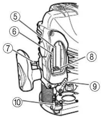
| 5 | Stopper pole | Anschlagstift | Πείρος αναστολής | Prowadnica dystansowa |
| 6 | Scale | Skala | Κλίμακα | Podziałka |
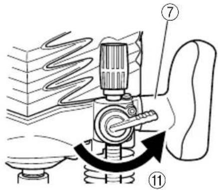
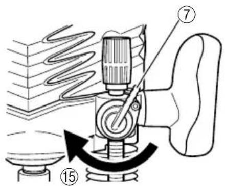
| 7 | Quick adjustment lever | Schnelleinstellhebel | Μοχλός ρύθμισης | Dźwignia szybkiej regulacji |
| 8 | Depth indicator | Tiefe-Indikator | Δείκτης βάθους | Wskaźnik głębokości |
| 9 | Pole lock knob | Schaftarretierungsknopf | Διακόπτης πείρου ασφάλισης | Pokrętło zaciskowe prowadnicy |
| 10 | Stopper block | Anschlagblock | Τάκος αναστολής | Element dystansowy |
| 11 | Counter-clockwise direction | Gegen den Uhrzeigersinn | Κατεύθυνση στη φορά των δεικτών του ρολογιού | Kierunek przeciwny do ruchu wskazówek zegara |
| 12 | Loosen the lock lever | Lösen des Sicherungshebels | Χαλαρώστε τον μοχλό του πείρου | Zwolnienie dźwigni blokady |
| 13 | Knob | Knopf | Κουμπί | Pokrętło |
| 14 | Fine adjustment knob | Feineinstellknopf | Κουμπί ρύθμισης ακριβείας | Pokrętło precyzyjnej regulacji |
| 15 | Clockwise direction | Im Uhrzeigersim | Με τη φορά των δεικτών του ρολογιού | Kierunek zgodny z ruchem wskazówek zegara |
| 16 | Cut depth setting screw | Einstellschraube der Frästiefe | Παξιμάδι ρύθμισης βάθους κοπής | Śruba nastawcza głębokości cięcia |
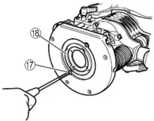
| 17 | Screw | Schraube | Παξιμάδι | Śruba |
| 18 | Template guide adapter | Vorlagenführungsadapter | Μετατροπέας οδηγού μοντέλου | Adapter prowadnicy wzornika |
| 19 | Centering gauge | Zentrierlehre | Ρυθμιστής κεντραρίσματος | Wskaźnik centrowania |
| 20 | Collet chuck | Spannfutter | Μηχανισμός σύσφιξης | Uchwyt zaciskowy |
| 21 | Template guide | Schablonenführung | Οδηγός μοντέλου | Prowadnica wzornika |
| 22 | Screw | Schraube | Παξιμάδι | Śruba |
| 23 | Template | Schablone | Μοντέλο | Wzornik |
| 24 | Bit | Fräse | Φρέζα | Frez |
| 25 | Straight guide | Gerade Führung/Parallelanschlag | Ευθύς οδηγός | Prowadnica wzdłużna |
| 26 | Guide plane | Führungsebene | Οδηγός επιφάνειας | Plaszczyzna prowadzenia |
| 27 | Bar holder | Stangenhalter | Συγκρατητήρας διευθύντριας ράβδου | Uchwyt mocujący |
| 28 | Feed screw | Vortriebschraube | Παξιμάδι τροφοδότησης | Śruba regulacyjna |
| 29 | Guide bar | Führungsstangen | Διευθύντρια ράβδος | Prowadnica |
| 30 | Wing bolt (A) | Flügelschraube (A) | Πεταλούδα (A) | Śruba skrzydełkowa (A) |
| 31 | Wing bolt (B) | Flügelschraube (B) | Πεταλούδα (B) | Śruba skrzydełkowa (B) |
| 32 | Tab | Lasche | Βάση | Języczek |
| 33 | Dust guide | Staubführung | Οδηγός σκόνης | System odprowadzania pyłu |
| 34 | Screw | Schraube | Παξιμάδι | Śruba |
| 35 | Dust guide adapter | Staubführungsadapter | Μετατροπέας οδηγού σκόνης | Złączka systemu odprowadzania pyłu |
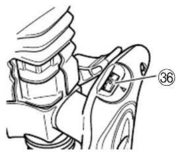
| 36 | Dial | Einstellscheibe | Επιλογέας | Tarcza regulacyjna |
| 37 | Stopper bolt | Stoppbolzen | Μπουλόνι στόπερ | Śruba dystansowa |
| 38 | Spring | Feder | Ελατήριο | Sprężyna |
| 39 | Separate | Abstand | Διαχωρίστε | Odstęp |
| 40 | Router feed | Vorschub der Oberfräse | Τροφοδότηση ρούτερ | Posuw frezarki pionowej |
| 41 | Workpiece | Werkstück | Κομμάτι για κατεργασία | Obrabiany element |
| 42 | Rotation of bit | Drehrichtung der Fräse | Περιστροφή φρέζας | Kierunek obrotu frezu |
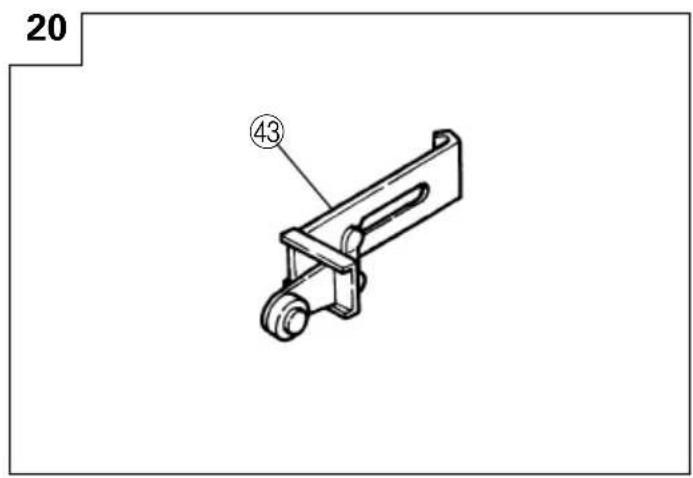
| 43 | Trimmer guide | Führung für das Zurichten | Οδηγός κοπής | Prowadnica okrojnika |
| 44 | Roller | Walze | Κύλινδρος | Rolka |
| Magyar | Čeština | Türkçe | Русский | |
| 1 | Rögzítő csap | Pojistný kolík | Kilit pimi | Стопорный штифт |
| 2 | Csavarkulcs | Klíč | Anahtar | Гаечный ключ |
| 3 | Meglazít | Uvolnit | Gevşet | Ослабить |
| 4 | Meghúz | Dotáhnout | Sıkıştır | Затянуть |
| 5 | Fékrúd | Tyčka zarážky | Stoper direk | Ограничитель |
| 6 | Beosztás | Stupnice | Ölçek | Шкала |
| 7 | Gyors beállító kar | Páka pro rychlé seřízení | Hızlı ayar kolu | Рычаг быстрого регулирования |
| 8 | Mélységjelző | Ukazatel hloubky | Derinlik göstergesi | Индикатор глубины |
| 9 | Rúd rögzítő gomb | Pojistný otočný knoflík tyčky | Direk kilitleme topuzu | Стопорная рукоятка |
| 10 | Fékblokk | Těleso zarážky | Stoper bloğu | Стопорный блок |
| 11 | Óramutató járásával ellentétes irány | Směr proti chodu hodinových ručiček | Saat yönünün tersine | Направление против часовой стрелки |
| 12 | Lazítsa meg a rögzítő kart | Uvolněte pojistnou páčku | Kilit kolu gevşetin | Ослабить стопорную рукоятку |
| 13 | Gomb | Otočná rukojeť | Topuz | Рукоятка |
| 14 | Finombeállító gomb | Otočná rukojeť pro jemné seřízení | Ince ayar topuzu | Рукоятка точной регулировки |
| 15 | Óramutató járásával megegyező irány | Ve směru chodu hodinových ručiček | Saat yönünde | Направление по часовой стрелке |
| 16 | Vágásmélység beállító csavar | Seřizovací šroub hloubky frézování | Kesme derinliği ayar vidası | Винт установки глубины резания |
| 17 | Csavar | Šroub | Vida | Винт |
| 18 | Sablon vezető adapter | Adaptér vedení šablony | Şablon kılavuz adaptörü | Переходник регулятора шаблона |
| 19 | Központosító idom | Měrka vystředění | Merkezleme mastari | Центровочное устройство |
| 20 | Patronos tokmány | Upínací pouzdro | Bağlama Aynası | Цанговый патрон |
| 21 | Sablon vezető | Vedení šablony | Şablon kılavuzu | Регулятор шаблона |
| 22 | Csavar | Šroub | Vida | Винт |
| 23 | Sablon | Šablona | Şablon | Шаблон |
| 24 | Fúróhegy | Nástavec | Uç | Резец |
| 25 | Egyenes vezető | Přimé vedení | Doğrusal kılavuzu | Прямое направляющее устройство |
| 26 | Vezető sík | Vodicí plocha | Kılavuz düzlemi | Направляющая пластина |
| 27 | Rúdtartó | Držák tyčky | Çubuk tutucu | Фиксатор бруса |
| 28 | Adagolócsiga | Posuvový šroub | Besleme vidası | Ходовой винт |
| 29 | Vezető rúd | Vodicí tyčka | Kılavuz çubuk | Опорный брус |
| 30 | Szárynas csavar (A) | Šroub s křídlovou hlavou (A) | Kelebek civatası (A) | Стопорный болт с загнутым стержнем (A) |
| 31 | Szárynas csavar (B) | Šroub s křídlovou hlavou (B) | Kelebek civatası (B) | Стопорный болт с загнутым стержнем (B) |
| 32 | Lap | Nos | Çıkıntı | Шпонка |
| 33 | Porelvezető | Vedení prachu | Toz kılavuzu | Устройство для направления пыли |
| 34 | Csavar | Šroub | Vida | Винт |
| 35 | Porelvezető adapter | Adaptér vedení prachu | Toz kılavuz adaptörü | Переходник устройства для направления пыли |
| 36 | Tárcsa | Stupnice | Kadran | Градуированный диск |
| 37 | Fék csavar | Šroub zarážky | Stoper civata | Стопорный болт |
| 38 | Rugó | Pružina | Yay | Пружина |
| 39 | Különválasztó | Vzdálenost | Ayırma | Разъединить |
| 40 | Felsőmaró toló | Posuv horní frézky | Freze besleme | Система питания фрезерного станка |
| 41 | Munkadarab | Obrobek | İş parçası | Заготовка |
| 42 | Fúróhegy forgása | Otáčení nástavce | Ucun dônüş yönü | Вращение резца |
| 43 | Szélező vezető | Vedení lemovače | Kırpma kılavuzu | Направляющая обрезного станка |
| 44 | Henger | Kladka | Teker | Валик |
| Symbols⚠ WARNINGThe following show symbols used for the machine. Be sure that you understand their meaning before use. | Symbole⚠ WARNINGDie folgenden Symbole werden für diese Maschine verwendet. Achten Sie darauf, diese vor der Verwendung zu verstehen. | Σύμβολα⚠ ΠΡΟΣΟΧΗΤα παρακάτω δείχνουν τα σύμβολα που χρησιμοποιούνται στο μηχάνημα. Βεβαωθείτε ότι κατανοείτε τη σημασίας τους πριν τη χρήση. | Symbole⚠ OSTRZEŻENIENastępujące oznaczenia to symbole używane w instrukcji obsługi maszyny. Upewnij się, że rozumiesz ich znaczenie zanim użyjesz narzędzia. | |
 | Read all safety warnings and all instructions.Failure to follow the warnings and instructions may result in electric shock, fire and/or serious injury. | Lesen Sie sämtliche Sicherheitshinweise und Anweisungen durch.Wenn die Warnungen und Anweisungen nicht befolgt werden, kann es zu Stromschlag, Brand und/oder ernsthaftenVerletzungen kommen. | Διαθάζετε όλες τις προειδοποιήσεις ασφαλείας και όλες τις οδηγίες.Η μη τήρηση των προειδοποιήσεων και οδηγιών μπορεί να προκαλέσειηλεκτροπληξία, πυρκαγιά και/ή σοβαρο τραυματισμό. | Należy dokładnie zapoznać się ze wszystkimi ostrzeżeniami i wskazówkami bezpieczeństwa.Nieprzestrzeganie ostrzeżeń oraz wskazówek bezpieczeństwa może spowodować porażenie prądem elektrycznym, pożar i/lub odniesienie poważnych obrażeń. |
 | Only for EU countriesDo not dispose of electric tools together with household waste material!In observance of European Directive 2002/96/EC on waste electrical and electronic equipment and its implementation in accordance with national law, electric tools that have reached the end of their life must be collected separately and returned to an environmentally compatible recycling facility. | Nur für EU-Länder Werfen SieElektrowerkzeuge nicht in den Hausmüll!Gemäss Europäischer Richtlinie 2002/96/EG über Elektro- und Elektronik-Altgeräte und Umsetzung in nationales Recht müssen verbrauchteElektrowerkzeuge getrennt gesammelt und einer umweltgerechten Wiederververtung zugeführt werden. | Móvo για τις χώρες της EEMην πετάτε τα ηλεκτρικά εργαλεία στον κάδο οικιακών απορριμμάτων!Σύμφωνα με την ευρωπαϊκη οδηγία 2002/96/ΕΚ περί ηλεκτρικών και ηλεκτρονικών συσκευών και την ενσωμάτωση της στο εθνικό δίκαιο, τα ηλεκτρικά εργαλεία πρέπει να συλλέγονταιξεχωριστά και να επιστρέφονται για ανακύκλωση με τρόπο φιλικό προς το περιβάλλον. | Dotyczy tylko państw UENie wyrzucaj elektronarzędzi wraz z odpadami z gospodarstwa domowego! Zgodnie z EuropejskąDyrektwyą 2002/96/WE w sprawie zużytego sprzętu elektrotechnicznego i elektronicznego oraz dostosowaniem jej do prawa krajowego, zużyte elektronarzędzia należy posegregować i zutylizować w sposób przyjazny dla środowiska. |
| Jelölések⚠ FIGYELEMAz alábbiakban a géphez alkalmazott jelölések vannak felsorolva. A gép használata előtt feltétlenül ismerje meg ezeket a jelöléseket. | Symboly⚠ UPOZORNĚNÍNásledující text obsahuje symboly, které jsou použity na zařizení. Ujistěte se, že rozumíte jejich obsahu před tím, než začnete zařizení používat. | Simgeler⚠ DIKKATAşağıda, bu alet için kullanılan simgeler gösterilmiştir. Aleti kullanmadan önce bu simgelerin ne anlama geldiğini anladığınızdan emin olún. | Символы⚠ ПРЕДУПРЕЖДЕНИЕНиже приведены символы, используемые для машины. Перед началом работы обязательно убедитесь в том, что Вы понимаете их значение. | |
 | Olvasson el minden biztonsági figyelmeztetést és minden utasítást.A figyelmeztetések és utasítások be nem tartása áramůtést, tüzet és/vagy súlyos sérülést eredményezhet. | Přecštěte si všechna varování týkající se bezpečnosti a všechny pokyny.Nedodržení těchto varování a pokynů může mít za následek elektrický šok, požár a/nebo vážné zranění. | Tüm güvenlik uyarılarının ve tüm talimatları okuyun. Uyarılara ve talimatlara uyulmaması elektrik çarpmasina, yangına ve/veya ciddi yaralanmaya neden olabilir. | Прочтите все правила безопасности и инструкции.Не выполнение правил и инструкций может привести к поражению электрическим током, пожару и/или серьезной травме. |
 | Csak EU-országok számára Az elektramos kéziszerszámokat ne dobja a háztartási szemétbe!A használt villamos és elektronikai készülékekról szóló 2002/96/EK irányelv és annak a nemzeti jogba való átültetése szerint az elhasznált elektromos kéziszerszámokat külön kell gyűjteni, és környezetbarát módon újra kell hasznosítani. | Jen pro státy EUElektrické náradí nevyhazujte do komunálního odpadu!Podle evropské směrnice 2002/96/EG o nakládání s použitými elektrickými a elektronickými zařizeními a odpovídajících ustanovení právních předpisů jednotlivých zemi se použitá elektrická nářadí musí sbírat odděleně od ostatního odpadu a podrobit ekologicky šetrnému recyklovaní. | Sadece AB ülkeleri için Elektrikli el aletlerini evdeki çöp kutusuna atmayınız! Kullanılmış elektrikli aletleri, elektrik ve elektronikli eski cihazlar hakkındaki 2002/96/EC Avrupa yönergelerine göre ve bu yönergeler ulusal hukuk kurallarina göre uyarlanarak, aynı olarak toplanmalı ve çevре şartlarına uygün bir şekilde tekrar değerlendirmeye gönderilmelidir. | Только для стран ECНе выкидывайте электроприборы вместе с обоычным мусором!В соответствии с европейской директивой 2002/96/EG ob утилизации старых электрических и электронных приборов и в соответствии с местными законами электроприборы, бывшие в эксплуатации, должны утилизовываться отдельно безопасным для окружающей среды способом. |
GENERAL POWER TOOL SAFETY WARNINGS
WARNING
Read all safety warnings and all instructions.
Failure to follow the warnings and instructions may result in electric shock, fire and/or serious injury.
Save all warnings and instructions for future reference.
The term "power tool" in the warnings refers to your mains-operated (corded) power tool or battery-operated (cordless) power tool.
1) Work area safety
a) Keep work area clean and well lit.
Cluttered or dark areas invite accidents.
b) Do not operate power tools in explosive atmospheres, such as in the presence of flammable liquids, gases or dust.
Power tools create sparks which may ignite the dust or fumes.
c) Keep children and bystanders away while operating a power tool.
Distractions can cause you to lose control.
2) Electrical safety
a) Power tool plugs must match the outlet.
Never modify the plug in any way.
Do not use any adapter plugs with earthed (grounded) power tools.
Unmodified plugs and matching outlets will reduce risk of electric shock.
b) Avoid body contact with earthed or grounded surfaces, such as pipes, radiators, ranges and refrigerators.
There is an increased risk of electric shock if your body is earthed or grounded.
c) Do not expose power tools to rain or wet conditions.
Water entering a power tool will increase the risk of electric shock.
d) Do not abuse the cord. Never use the cord for carrying, pulling or unplugging the power tool.
Keep cord away from heat, oil, sharp edges or moving parts.
Damaged or entangled cords increase the risk of electric shock.
e) When operating a power tool outdoors, use an extension cord suitable for outdoor use.
Use of a cord suitable for outdoor use reduces the risk of electric shock.
f) If operating a power tool in a damp location is unavoidable, use a residual current device (RCD) protected supply.
Use of an RCD reduces the risk of electric shock.
3) Personal safety
a) Stay alert, watch what you are doing and use common sense when operating a power tool.
Do not use a power tool while you are tired or under the influence of drugs, alcohol or medication.
A moment of inattention while operating power tools may result in serious personal injury.
b) Use personal protective equipment. Always wear eye protection.
Protective equipment such as dust mask, non-skid safety shoes, hard hat, or hearing protection used for appropriate conditions will reduce personal injuries.
c) Prevent unintentional starting. Ensure the switch is in the off-position before connecting to power source and/or battery pack, picking up or carrying the tool.
Carrying power tools with your finger on the switch or energising power tools that have the switch on invites accidents.
d) Remove any adjusting key or wrench before turning the power tool on.
A wrench or a key left attached to a rotating part of the power tool may result in personal injury.
e) Do not overreach. Keep proper footing and balance at all times.
This enables better control of the power tool in unexpected situations.
f) Dress properly. Do not wear loose clothing or jewellery. Keep your hair, clothing and gloves away from moving parts.
Loose clothes, jewellery or long hair can be caught in moving parts.
g) If devices are provided for the connection of dust extraction and collection facilities, ensure these are connected and properly used.
Use of dust collection can reduce dust related hazards.
4) Power tool use and care
a) Do not force the power tool. Use the correct power tool for your application.
The correct power tool will do the job better and safer at the rate for which it was designed.
b) Do not use the power tool if the switch does not turn it on and off.
Any power tool that cannot be controlled with the switch is dangerous and must be repaired.
c) Disconnect the plug from the power source and/or the battery pack from the power tool before making any adjustments, changing accessories, or storing power tools.
Such preventive safety measures reduce the risk of starting the power tool accidentally.
d) Store idle power tools out of the reach of children and do not allow persons unfamiliar with the power tool or these instructions to operate the power tool. Power tools are dangerous in the hands of untrained users.
e) Maintain power tools. Check for misalignment or binding of moving parts, breakage of parts and any other condition that may affect the power tool's operation.
If damaged, have the power tool repaired before use. Many accidents are caused by poorly maintained power tools.
f) Keep cutting tools sharp and clean.
Properly maintained cutting tools with sharp cutting edges are less likely to bind and are easier to control.
g) Use the power tool, accessories and tool bits etc. in accordance with these instructions, taking into account the working conditions and the work to be performed.
Use of the power tool for operations different from those intended could result in a hazardous situation.
5) Service
a) Have your power tool serviced by a qualified repair person using only identical replacement parts.
This will ensure that the safety of the power tool is maintained.
PRECAUTION
Keep children and infirm persons away.
When not in use, tools should be stored out of reach of children and infirm persons.
PRECAUTIONS ON USING ROUTER
- Single-hand operation is unstable and dangerous. Ensure that both handles are gripped firmly during operation.
- The bit is very hot immediately after operation. Avoid bare hand contact with the bit for any reason.
SPECIFICATIONS
| Model M12V2 M12SA2 | ||
| Voltage (by areas)* (110V, 120V, 220V, 230V, 240V) | ||
| Power Input* 2000 W 1700 W | ||
| Collet Chuck Capacity 12 mm or 1/2" | ||
| No-load speed 8000 – 22000 min | -1 | 22000 min-1 |
| Main Body Stroke 65 mm | ||
| Weight (without cord and standard accessories) | 6.3 kg 6.2 kg | |
*Be sure to check the nameplate on product as it is subject to change by areas.
STANDARD ACCESSORIES
(1) Straight Guide 1
(2) Bar Holder 1
Guide Bar 2
Feed Screw 1
Wing Bolt 1
(3) Dust Guide 1
(4) Dust Guide Adapter 1
(5) Template Guide 1
(6) Template Guide Adapter 1
(7) Centering Gauge 1
(8) Knob 1
(9) Wrench 1
(10) 8mm or 1/4" Collet Chuck ....
(11) Wing Bolt (A)
(12) Lock Spring ....
Standard accessories are subject to change without notice.
OPTIONAL ACCESORIES - sold separately
(1) Template Guide

| A | B | C |
| 16.5 mm | 18 mm | 4.5 mm |
| 18.5 mm | 20 mm | |
| 25.5 mm | 27 mm | |
| 28.5 mm | 30 mm |
(2) Chuck sleeve

| D | d | Shape of chuck sleeve | |
| 12 mm | 6 mm |  | No groove |
| 3/8" |  | 1 groove | |
| 1/2" | 3/8" | 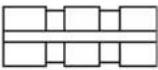 | 2 grooves |
| 10 mm |  | No groove | |
(3) Trimmer Guide (Fig. 20)
(4) Template Guide Adapter (B)
For the product of Trend.
Optional accessories are subject to change without notice.
APPLICATIONS
○Woodworking jobs centered on grooving and chamfering.
PRIOR TO OPERATION
1. Power source
Ensure that the power source to be utilized conforms to the power requirements specified on the product nameplate.
2. Power switch
Ensure that the power switch is in the OFF position. If the plug is connected to a receptacle while the power switch is in the ON position, the power tool will start operating immediately, which could cause a serious accident.
3. Extension cord
When the work area is removed from the power source, use an extension cord of sufficient thickness and rated capacity. The extension cord should be kept as short as practicable.
INSTALLING AND REMOVING BITS
WARNING
Be sure to switch power OFF and disconnect the plug from the receptacle to avoid serious trouble.
1. Installing bits
(1) Clean and insert shank of bit into the collet chuck until shank bottoms, then back it out approximately 2 mm.
(2) With the bit inserted and pressing the lock pin holding the armature shaft, use the 23 mm wrench to firmly tighten the collet chunk in a clockwise direction (viewed from under the router). (Fig. 1)
CAUTION
○Ensure that the collet chuck is firmly tightened after inserting a bit. Failure to do so will result in damage to the collet chuck.
☐Ensure that the lock pin is not inserted into the armature shaft after tightening the collet chuck. Failure to do so will result in damage to the collet chuck, lock pin and armature shaft.
(3) When using the 8 mm diameter shank bit, replace the equipped collet chuck with the one for 8mm diameter shank bit which is provided as the standard accessory.
2. Removing Bits
When removing the bits, do so by following the steps for installing bits in reverse order.
CAUTION
Ensure that the lock pin is not inserted into the armature shaft after tightening the collet chuck. Failure to do so will result in damage to the collet chuck, lock pin and armature shaft.
HOW TO USE THE ROUTER
1. Adjusting depth of cut (Fig. 2)
(1) Place the tool on a flat wood surface.
(2) Turn the quick adjustment lever in a counterclockwise direction until the quick adjustment lever stops. (Fig. 3)
(3) Turn the stopper block so that section to which the cutting depth setting screw on a stopper block is not attached comes to the bottom of the stopper pole. Loosen pole lock knob allowing the stopper pole to contact with stopper block.
(4) Loosen the lock lever and press the tool body until the bit just touches the flat surface. Tighten the lock lever at this point. (Fig. 4)
(5) Tighten pole lock knob. Align the depth indicator with the "0" graduation of scale.
(6) Loosen pole lock knob, and raise until indicator aligns with the graduation representing the desired cutting depth. Tighten pole lock knob.
(7) Loosen the lock lever and press the tool body down until the stopper block to obtain the desired cutting depth.
Your router allows you to finely adjust depth of cut.
(1) Attach knob to fine adjustment knob.
(2) Turn the quick adjustment lever in a clockwise direction until the quick adjustment lever stops with the stopper screw. (Fig. 5)
If the quick adjustment lever does not stop with the stopper screw, the bolt screw is not properly fitted. If this occurs, slightly loosen the lock lever and press down on the unit (router) hard from the top and turn the quick adjustment lever again after properly fitting the bolt screw.
(3) The depth of cut can be adjusted when the lock lever is loosened, by turning the fine adjustment knob. Turning the fine adjustment knob counterclockwise results in shallower cut, whereas turning it clockwise results in a deeper cut.
CAUTION
Ensure that the lock lever is tightened after finely adjusting depth of cut. Failure to do so will result in damage to the quick adjustment lever.
2. Stopper block (Fig. 6)
The 2 cut-depth setting screws attached to the stopper block can be adjusted to simultaneously set 3 different cutting depth. Use a wrench to tighten the nuts so that the cut-depth setting screws do not come loose at this time.
3. Guiding the router
WARNING
Be sure to switch power OFF and disconnect the plug from the receptacle to avoid serious trouble.
(1) Template guide adapter
①Loosen the 2 template guide adapter screws, so that the template guide adapter can be moved. (Fig. 8)
②Insert the centering gauge through the hole in the template guide adapter and into the collet chuck. (Fig. 9)
③Tighten the collet chuck by hand.
④ Tighten the template guide adapter screws, and pull out the centering gauge.
(2) Template guide
Use the template guide when employing a template for producing a large quantity of identically shaped products. (Fig. 10)
As shown in Fig. 11, to install insert template guide in center hole in template guide adapter with 2 accessory screws.
A template is a profiling mold made of plywood or thin lumber. When making a template, pay particular attention to the matters described below and illustrated in Fig. 12.
When using the router along the interior plane of the template, the dimensions of the finished product will be less than the dimensions of the template by an amount equal to dimension "A", the difference
between the radius of the template guide and the radius of the bit. The reverse is true when using the router along the exterior of the template.
(3) Straight guide
Use straight guide for chamfering and groove cutting along the materials side.
①Insert the guide bar into the hole in the bar holder, then lightly tighten the 2 wing bolts (A) on top of the bar holder.
②Insert the guide bar into the hole in the base, then firmly tighten the wing bolts (A).
③Make minute adjustments of the dimensions between the bit and the guide surface with the feed screw, then firmly tighten the 2 wing bolt (A) on top of the bar holder and the wing bolt (B) that secures the straight guide.
④As shown in Fig. 14, securely attach the bottom of the base to processed surface of the materials. Feed the router while keeping the guide plane on the surface of the materials.
(4) Dust guide and Dust guide adapter (Fig. 15)
Your router is equipped with dust guide and a dust guide adapter.
①Match the 2 grooves on the base and insert the 2 dust guide tabs in holes located in the base side from the top. Tighten the dust guide with a screw. The dust guide diverts cutting debris away from the operator and directs the discharge in a consistent direction.
②By fitting the dust guide adapter into the dust guide cutting debris discharge vent, the dust extractor can be attached.
- Adjusting the rotation speed (Model M12V2 only) The M12V2 has an electronic control system that allows stepless rpm changes.
As shown in Fig. 16, dial position "1" is for minimum speed, and position "6" for maximum speed.
- Removing the spring
The springs within the column of the router can be removed. Doing so will eliminate spring resistance and allows easy adjustment of cutting depth when attaching the router stand.
(1) Loosen the 4 sub base screws, and remove the sub base.
(2) Loosen the stopper bolt and remove it, so the spring can be removed. (Fig. 17)
CAUTION
Remove the stopper bolt with the main unit (router) fixed at its maximum height.
Removing the stopper bolt with the unit in a shortened condition may cause the stopper bolt and spring to be discharged and cause injury.
- Cutting
CAUTION
○Wear eye protection when operating this tool.
Keep your hands, face and other body parts away from the bits and any other rotating parts, while operating the tool.
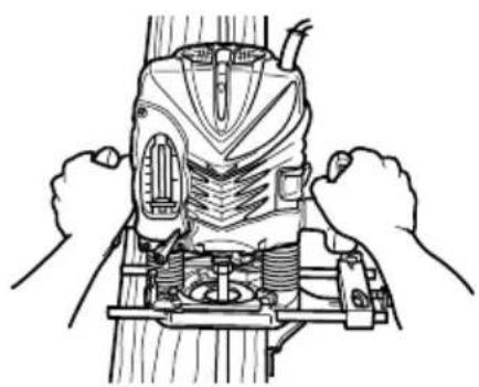
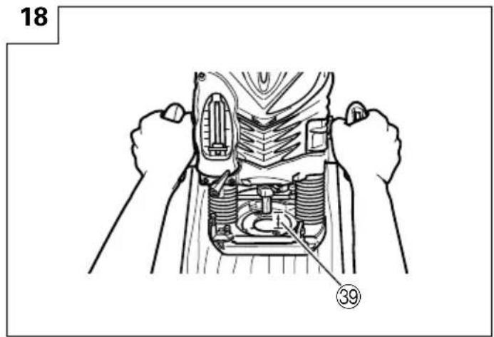
(1) As shown in Fig. 18, remove the bit from the work pieces and press the switch lever up to the ON position. Do not start cutting operation until the bit has reached full rotating speed.
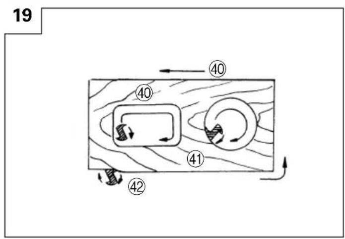
(2) The bit rotates clockwise (arrow direction indicated on the base). To obtain maximum cutting effectiveness, feed the router in conformance with the feed directions shown in Fig. 19.
NOTE
If a worn bit is used to make deep grooves, a high pitched cutting noise may be produced.
Replacing the worn bit with a new one will eliminate the high pitched noise.
USING THE OPTIONAL ACCESSORIES
Trimmer Guide (Fig. 20):
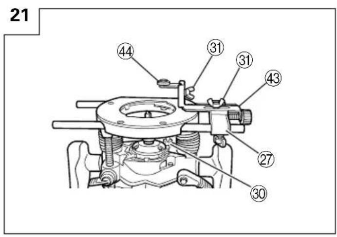
Use the trimmer guide for trimming or chamfering. Attach the trimmer guide to the bar holder as shown in Fig. 21.
After aligning the roller to the appropriate position, tighten the two wing bolts (A) and the other two wing bolts (B). Use as shown in Fig. 22.
MAINTENANCE AND INSPECTION
- Oiling
To ensure smooth vertical movement of the router, occasionally apply a few drops of machine oil to the sliding portions of the columns and end bracket.
- Inspecting the mounting screws
Regularly inspect all mounting screws and ensure that they are properly tightened. Should any of the screws be loose, retighten them immediately. Failure to do so could result in serious hazard.
- Maintenance of the motor
The motor unit winding is the very "heart" of the power tool.
Exercise due care to ensure the winding does not become damaged and/or wet with oil or water.
- Inspecting the carbon brushes
For your continued safety and electrical shock protection, carbon brush inspection and replacement on this tool should ONLY be performed by a HITACHI AUTHORIZED SERVICE CENTER.
- Replacing supply cord
If the supply cord of Tool is damaged, the Tool must be returned to Hitachi Authorized Service Center for the cord to be replaced.
- Service parts list
A: Item No.
B: Code No.
C: No. Used
D: Remarks
CAUTION
Repair, modification and inspection of Hitachi Power Tools must be carried out by an Hitachi Authorized Service Center.
This Parts List will be helpful if presented with the tool to the Hitachi Authorized Service Center when requesting repair or other maintenance.
In the operation and maintenance of power tools, the safety regulations and standards prescribed in each country must be observed.
MODIFICATIONS
Hitachi Power Tools are constantly being improved and modified to incorporate the latest technological advancements.
Accordingly, some parts (i.e. code numbers and/or design) may be changed without prior notice.
GUARANTEE
We guarantee Hitachi Power Tools in accordance with statutory/country specific regulation. This guarantee does not cover defects or damage due to misuse, abuse, or normal wear and tear. In case of complaint, please send the Power Tool, undismantled, with the GUARANTEE CERTIFICATE found at the end of this Handling instruction, to a Hitachi Authorized Service Center.
NOTE
Due to HITACHI's continuing program of research and development, the specifications herein are subject to change without prior notice.
Information concerning airborne noise and vibration
The measured values were determined according to EN 60745 and declared in accordance with ISO 4871.
M12V2
Measured A-weighted sound power level: 96 dB(A) Measured A-weighted sound pressure level: 83 dB(A) Uncertainty KpA: 3 dB(A)
The typical weighted root mean square acceleration value: 1.0 m/s^2 .
M12SA2
Measured A-weighted sound power level: 97 dB(A) Measured A-weighted sound pressure level: 84 dB(A) Uncertainty KpA: 3 dB(A)
The typical weighted root mean square acceleration value: 1.3 m/s^2 .
Wear ear protection.
(9) Schraubenschlüssel 1
natural_image
Line drawing of a quill pen in an inkwell (no text or symbols)| English | Magyar | ||
| GUARANTEE CERTIFICATE | GARANCIA BIZONYLAT | ||
| 1Model No.2Serial No.3Date of Purchase4Customer Name and Address5Dealer Name and Address(Please stamp dealer name and address) | 1Típusszám2Sorozatszám3A vásárlás dátuma4A Vásárló neve és címe5A Kereskedő neve és címe(Kérjük ide elhelyezni a Kereskedő nevének és címének pecsétjét) | ||
| Deutsch | Čeština | ||
| GARANTIESCHEIN | ZÁRUČNÍ LIST | ||
| 1Modell-Nr.2Serien-Nr.3Kaufdaturn4Name und Anschrift des Kunden5Name und Anschrift des Händlers(Bitte mit Namen und Anschrift des Handlers abstempeln) | 1Model č.2Série č.3Datum nákupu4Jméno a adresa zákazníka5Jméno a adresa prodejce(Prosíme o razítko se jménem a adresou prodejce) | ||
| Ελληνικά | Türkçe | ||
| ΠΙΣΤΟΠΟΙΗΤΙΚΟ ΕΓΓΥΗΣΗΣ | GARANTI SERTÍFÍKASI | ||
| 1Ap. Movtělou2Aùξων Ap.3Ημερομηνία αγοράς4Όνομα και διεύθυνση πελάτη5Όνομα και διεύθυνση μεταπωλητή(Παρακαλούμε να χρησιμοποιηθεί σφραγίδα) | 1Model No.2Seri No.3Satın Alma Tarihi4Müşteri Adı ve Adresi5Bayi Adı ve Adresi(Lütfen bayi adını ve adresini kaşe olarak basın) | ||
| Polski Русский | |||
| GWARANCJA | ГАРАНТИЙНЫЙ СЕРТИФИКАТ | ||
| 1Model2Numer seryjny3Data zakupu4Nazwa klienta i adres5Nazwa dealera i adres(Pieczęć punktu sprzedaży) | 1Модель No2Серийный No3Дата покупки4Название и адрес заказчика5Название и адрес дилера(Пожалуйста, внесите название и адрес дилера) | ||
HITACHI
| 1 | |
| 2 | |
| 3 | |
| 4 | |
| 5 |
Hitachi Koki
Hitachi Power Tools Netherlands B.V. Moscow Branch
Kashirskoye Shosse Dom 65, 4F
115583 Moscow, Russia
Tel: +7 495 727 4460 or 4462
Fax: +7 495 727 4461
URL: http://www.hitachi-pt.ru
Hitachi Power Tools Romania
Str Sf. Gheorghe nr 20-Ferma, Pantelimon, Jud. Llfov
Tel: +031 805 25 77
Fax: +031 805 27 19
| English | EC DECLARATION OF CONFORMITYWe declare under our sole responsibility that this product is in conformity with standards or standardized documents EN60745, EN55014 and EN61000 in accordance with Council Directives 2004/108/EC and 98/37/EC.This declaration is applicable to the product affixed CE marking. | Magyar | EU MEGFELELŐSÉGI NYILATKOZATTeljes felelősségünk tudatában kijelentjük, hogy ez a termék megfelel az EN60745, EN55014, és EN 61000 szabványoknak illetve szabványosított dokumentumoknak, az Európa Tanács 2004/108/EC, és 98/37/EC Tanácsi Direktíváival összhangban.Jelen nyilatkozat a terméken feltüntetett CE jelzésre vonatkozik. |
| Deutsch | ERKLÄRUNG ZUR KONFORMITÄT MIT CE-REGELNWir erklären mit alleiniger Verantwortung, daß dieses Produkt den Standards oder standardisierten Dokumenten EN60745, EN55014 und EN61000 in Übereinstimmung mit den Direktiven des Europarats 2004/108/CE und 98/37/CE entspricht.Diese Erklärung gilt für Produkte, die die CE-Markierung tragen. | Čeština | PROHLÁŠENÍ O SHODĚ S CEProhlašujeme na svoji zodpovědnost, že tento výrobek odpovídá normám EN60745, EN55014 a EN61000 v souladu se směrnicemi 2004/108/EC a 98/37/EC.Toto prohlášení platí pro výrobek označený značkou CE. |
| Ελληνικά | EK ΔΗΛΩΣΗ ENAPMONΙΣΜΟΥΔηλώνουμε με απόλυτη υπευθυνότητα ότι αυτό το προϊόν είναι εναρμονιςμένο με τα πρότυπα ή τα έγραφα προτύπων EN60745, EN55014 και EN61000 çε ζυμφωνία με τις Οδηγίες του Συμβουλίου 2004/108/ EK και 98/37/EK.Autή η δήλωςη ιςχύει στο προϊόν με το ζημάδι CE. | Türkçe | AB UYGUNLUK BEYANIBu ürünün, 2004/108/EC ve 98/37/EC sayılı Konsey Direktiflerine uygun olarak, EN60745, EN55014 ve EN61000 sayılı standartlara ve standartlaştırılmış belgelere uygun olduğunu, tamamen kendi sorumluluğumuz altında beyan ederiz.Bu beyan, üzerinde CE işareti bulunan ürünler için geçerlidir. |
| Polski | DEKLARACJA ZGODNOŚCI Z ECOznajmiamy z całkowitą odpowiedzialnością, że produkt ten pozostaje w zgodzie ze standardami lub standardową formą dokumentów EN60745, EN55014 i EN61000 w zgodzie z Zasadami Rady 2004/108/ EC i 98/37/EC.To oświadczenie odnosi się do załączonego produktu z oznaczeniami CE. | Русский | ДЕКЛАРАЦИЯ СООТВЕТСТВИЯ ЕСМы с полной ответственностью заявляем, что данное изделие соответствует стандартам или стандартизованным документам EN60745, EN55014 и EN61000 согласно Директивам Совета 2004/108/EC и 98/37/EC.Данная декларация относится к изделиям, на которых имеется маркировка CE. |
| Representative office in EuropeHitachi Power Tools Europe GmbHSiemensring 34, 47877 Willich 1, F. R. GermanyHead office in JapanHitachi Koki Co., Ltd.Shinagawa Intercity Tower A, 15-1, Konan 2-chome,Minato-ku, Tokyo, Japan | 30. 1. 2009M. KatoK. KatoBoard Director | ||

Hitachi Koki Co., Ltd.
- GENERAL POWER TOOL SAFETY WARNINGS
- WARNING
- Save all warnings and instructions for future reference.
- 1) Work area safety
- 2) Electrical safety
- 3) Personal safety
- 4) Power tool use and care
- 5) Service
- PRECAUTION
- PRECAUTIONS ON USING ROUTER
- STANDARD ACCESSORIES
- OPTIONAL ACCESORIES - sold separately
- APPLICATIONS
- PRIOR TO OPERATION
- Power source
- Power switch
- Extension cord
- INSTALLING AND REMOVING BITS
- Installing bits
- CAUTION
- Removing Bits
- HOW TO USE THE ROUTER
- Adjusting depth of cut (Fig. 2)
- Your router allows you to finely adjust depth of cut.
- Stopper block (Fig. 6)
- Guiding the router
- USING THE OPTIONAL ACCESSORIES
- MAINTENANCE AND INSPECTION
- GUARANTEE
- NOTE
- Information concerning airborne noise and vibration
- M12V2
- M12SA2
- Hitachi Power Tools Netherlands B.V. Moscow Branch
- Hitachi Power Tools Romania
- Hitachi Koki Co., Ltd.
Brand : HiKOKI
Model : M 12SA2
Category : Saw