
PDT 40 A1 - Stapler PARKSIDE - Free user manual and instructions
Find the device manual for free PDT 40 A1 PARKSIDE in PDF.


| Product Type | Manual Stapler / Staple Gun |
| Model | PDT 40 A1 |
| Brand | Parkside |
| Dimensions (approx.) | 220 x 50 x 170 mm |
| Weight (approx.) | 0.35 kg |
| Power Source | Manual (hand-operated) |
| Staple Type | Type 40 (6-14 mm leg length) |
| Magazine Capacity | 100 staples |
| Material | Plastic housing, metal base |
| Main Functions | Stapling paper, cardboard, fabric; tacking insulation, cables |
| Operating Force | Approx. 40 N (low effort) |
| Safety Features | Trigger lock, jam release mechanism |
| Maintenance | Clean with dry cloth; lubricate moving parts occasionally |
| Spare Parts Availability | Replacement springs and anvils available online |
| Repairability | User-replaceable parts; easy disassembly |
| Intended Use | DIY, home improvement, upholstery |
| Included Accessories | 100 staples, user manual |
| Warranty | 3 years (Parkside standard) |
Frequently Asked Questions - PDT 40 A1 PARKSIDE
User questions about PDT 40 A1 PARKSIDE
0 question about this device. Answer the ones you know or ask your own.
Ask a new question about this device
Download the instructions for your Stapler in PDF format for free! Find your manual PDT 40 A1 - PARKSIDE and take your electronic device back in hand. On this page are published all the documents necessary for the use of your device. PDT 40 A1 by PARKSIDE.
USER MANUAL PDT 40 A1 PARKSIDE
natural_image
Green Parkside PDT 40 A1 kit on wooden workbench with safety gear and binder nearby (no visible text or symbols)GB IE CY
AIR NAILER / STAPLER SET
Operation and Safety Notes Original operating instructions
SE
HÄFT- OCH SPIKPISTOL SET
DRUCKLUFT-TACKER-SET
Before reading, unfold the page containing the illustrations and familiarise yourself with all functions of the device.
FI
GB/IE/CY Operation and Safety Notes Page 5
natural_image
Close-up of a green and black electric shaver with a red handle, showing internal components and no visible text or symbols.
natural_image
Close-up of a black metal frame with a textured rectangular object on one end, no visible text or symbols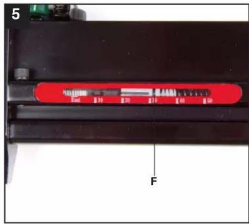
natural_image
Close-up of a mechanical assembly with black and green components, no visible text or symbols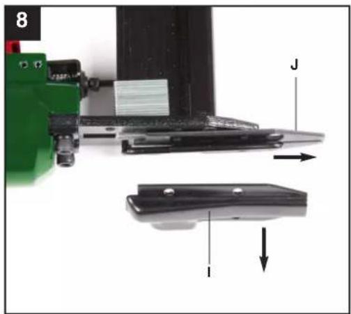
natural_image
Close-up of a mechanical assembly with labeled parts (J, I) and directional arrows, no readable text or symbols beyond labelsTable of contents: Page
- Introduction ......7
- Safety Information 7-8
- Layout 8
- Items supplied 8
- Intended use....8-9
- Technical data 9-10
- Starting up 10-11
- Care and maintenance 12
- Cleaning and ordering spare parts .....12
- Disposal and recycling ....12
- Excluded from the guarantee ....13
- Declaration of conformity 14-15
- Guarantee certificate .... 16
The reprinting or reproduction by any other means, in whole or in part, of documentation and papers accompanying products is permitted only with the express consent of the ISC GmbH.
Subject to technical changes

Additional safety instructions

"Caution - Read the operating instructions to reduce the risk of inquiry"

Wear ear-muffs.
The impact of noise can cause damage to hearing.

Wear safety goggles.
Sparks generated during working or splinters, chips and dust emitted by the device can cause loss of sight.

Do not use on platforms and ladders.
1. Introduction
⚠️ Important.
When using the equipment, a few safety precautions must be observed to avoid injuries and damage. Please read the complete operating manual with due care. Keep this manual in a safe place so that the information is available at all times. If you give the equipment to any other person, hand over these operating instructions as well. We cannot accept any liability for damage or accidents which arise due to a failure to follow these instructions and the safety information.
2. Safety Information
CAUTION
Read all the safety regulations and
instructions. Any errors made in following the safety regulations and instructions may result in an electric shock, fire and/or serious injury.
Keep all safety regulations and instructions in a safe place for future use.
Protect yourself and your environment from accidents by taking the appropriate precautionary measures.
■ Do not use the stapler for a purpose for which it is not designed.
■ Keep air tools safe from children.
■ Never use the equipment when you are not rested or distracted.
■ Connect the compressed air using a quick-lock coupling only.
■ Staplers may only be connected to lines/hoses which do not allow the maximum permitted pressure of the equipment to be exceeded by more than 10%. A pressure regulator (pressure reducer) with a downstream pressure control valve must be fitted to the compressed air hose if the pressure is higher.
■ The operating pressure must be adjusted by a pressure reducer.
■ When using a pneumatically operated stapler/nailer, only use the pressure required for the specific operation to prevent an unnecessarily high noise level, excessive wear and consequential faults.
■ Never use oxygen or combustible gases as a power source. Danger of fire and explosion.
■ Always disconnect the equipment from the compressed air source before tackling faults or starting any maintenance work.
■ Use only genuine spare parts. Repairs may only be carried out by an authorized agent of the manufacturer or by an alternative specialist in accordance with the specifications contained in the operating instructions.
■ Wear the necessary protective clothing when working with the stapler, in particular safety goggles and protective gloves.
■ Do not exceed the maximum air pressure of 8 bar.
■ Do not direct the connected and loaded nailer at other people.
■ Do not remove the earthing contact device.
■ Never leave the equipment unattended when loaded.
■ Never use the equipment if defective.
■ Only use the types of staples/nails specified in the technical data.
■ The equipment must always be depressurized after disconnection.
■ Never use the equipment without staples/nails.
■ Never point an operational stapler directly at yourself or at any other person.
■ Whilst working with the stapler, hold it in such a way that your head and body cannot be injured in case of kickback caused by disruption of the power supply or by hard areas of the workpiece.
■ Never trigger the stapler into the open air. This is important to avoid the hazards of free-flying staples and of overloading the appliance.
■ For the purposes of transportation, the stapler must be disconnected from the compressed-air system, especially if you are using a ladder or are adopting an unusual posture.
GB/IE/CY
■ In the workplace, carry the stapler only by its handle and ensure that the trigger is inactivated.
■ Make allowance for the workplace conditions. Staples can potentially go straight through thin workpieces or they can slide off workpieces when working on corners and edges, thus putting persons at risk.
■ For you own personal safety, always use suitable protective equipment such as, for example, hearing and eye protection.
■ Check that the trigger catch functions correctly every time before you use the equipment. You are allowed to start using the equipment only if the device functions perfectly.
This equipment is not suitable for the following work:
■ If changing from one stapling point to another involves moving about on platforms, steps, ladders or any other structures similar to ladders such as, e.g. roof battens.
■ Sealing of boxes or crates.
■ Fitting of transportation braces, e.g. to vehicles and wagons
Do not lose this safety information.
Residual risks
Even if you use this tool in accordance with instructions, certain residual risks cannot be eliminated. The following hazards may arise in connection with the equipment's construction and layout:
- Risk of pinching.
- Risk of injury from staples.
- Damage to hearing, if no suitable ear protection is applied.
- Health damage caused by hand-arm vibrations, if the equipment is not properly guided and maintained.
3. Layout (Fig. 1)
A Trigger lever
B Compressed air connection
C Magazine lever
D Magazine cover
E Magazine
F Level indicator
G Depth setting
H Trigger catch
I Cover plate (external)
J Cover plate (Internal)
K Swivel air-outlet
4. Items supplied (Fig. 2)
L Safety goggles
M Special compressed air oil
N Allen key, 3 mm
O Allen key, 4 mm
Not illustrated:
■ 250 x 15 mm, 25 mm, 40 mm, 50 mm nails of each size
■ 250 x 16 mm staples, 500 x 25 mm staples, 250 x 40 mm staples
5. Intended use
The stapler is a pneumatically operated tool designed for versatile use.
This equipment is designed for driving finishing nails and staples into wood and similar materials. Only use the types of nails/staples described in the “Technical data” section or illustrated on the information sign on the magazine. Never use any other nails/staples. Never use on hard surfaces such as stone, metal, etc., either.
The equipment may only be used for the tasks it is designed to handle. Any other use is deemed to be a case of misuse. The user/operator and not the manufacturer will be liable for any damage or injuries of any kind caused as a result of this.
Please note that our equipment has not been designed for use in commercial, trade or industrial applications. Our warranty will be voided if the equipment is used in commercial, trade or industrial businesses or for equivalent purposes.
Only allow repairs and services to be carried out by authorized professional repair shops.
Remember.
If the inner diameter of the hose is insufficient and the length of the hose too long, this will result in a loss of power on the equipment.
6. Technical data
Max. permitted operating pressure 8 bar
Recommended pressure range 4 - 7.5 bar
Air consumption approx. 0.11 l/shot
Staple width 5.7 mm
Staple length 13 - 40 mm
Nail length 10 - 50 mm
Recommended hose diameter Diameter 9 mm
Weight approx. 1,3 kg
L_pA sound pressure level 85.5 dB(A)
L_WA sound power level 98.8 dB(A)
L_PC sound pressure level 113.6 dB(A)
Vibration a_w ≤ 2.5 m/s^2
K uncertainty 27.93%
These values for noise emissions are equipment-based characteristic values and do not reflect the noise generated at the place of use. The noise generated at the place of use will depend, for example, on the work area, the workpiece, workpiece support and the number of stapling/nailing operations.
The value given for vibration is an equipment-based characteristic value and does not represent the impact on the hand and arm system when the equipment is used. The impact on the hand and arm system when the equipment is used will depend, for example, on the force of the grip, the pressing force, the direction in which you are working, the air pressure setting, the workpiece and the workpiece support.
Reduce noise generation and vibration to a minimum!
■ Use only equipment that is in perfect condition.
■ Maintain and clean the equipment regularly.
■ Adopt your way of working to the equipment.
■ Do not overload the equipment.
■ Have the equipment checked if necessary.
■ Switch off the equipment when not in use.
■ Wear gloves.
Compressed air quality:
Purified and with oil mist.
Air supply:
Via a conditioning unit with filter pressure reducer and mist oiler connected to a compressed air source.
Recommended capacity of the compressor:
Compressor with a capacity of approx. 250 l/min, which is the equivalent of engine power of approx. 2.2 kW
Remember:
Wear the necessary protective clothing when working with the stapler, in particular safety goggles.
Pay attention to the safety regulations.
6.1 Safety goggles (SF026)
The safety goggles (Fig. 2/Item L) are intended to provide protection for the eyes, against small parts flying at high speed and are intended to protect the user against injury.
For optimum protection the safety goggles should be adjusted by lengthening or shortening the strap to make them fit correctly. Adjusting the goggles: Slide the strap along the latch to adjust the length of the strap.
GB/IE/CY
ID number, name and address of the test organization
N.B. 0196
Explanation of the symbols on the safety goggles
1: Optical class
F: Mechanical strength (45 m/s)
166: Number of the standard (EN 166)
Cleaning
Clean the goggles at regular intervals using lukewarm water and a little lubricant soap. Do not use cleaning agents or solvents; these may be aggressive to the plastic.
Storage
Do not store the goggles in extremely hot environments where they may be exposed to UV radiation. This may reduce the service life of the plastic. Store the goggles in a cool dark place when they are not in use.
Working life
Replace the goggles if the viewing screens get scratched or damaged or if the frame gets damaged.
Transport
The safety goggles can be kept in the transport case.
Warnings
If spectacles are worn behind the safety goggles there is a danger of harm to the user from the possibility of the transfer of impacts from particles flying at high speed.
Materials coming into contact with the user's skin may cause allergies among people who are sensitive.
Never work with safety goggles which have a scratched or damaged viewing screen.
7. Starting up
■ Each time before starting work, check that the trigger catch functions perfectly and that all screws and nuts are securely fastened.
■ Never tamper with the stapler.
■ Never dismantle or block any parts of the stapler such as, e.g. a trigger catch.
■ Never carry out any “emergency repairs” with unsuitable means.
■ Proper stapler maintenance is required at regular intervals in accordance with the information supplied by the manufacturer.
■ Take precautions to prevent anything which would weaken or damage the equipment, e.g. from
a) striking or engraving,
b) modifications which are prohibited by the manufacturer,
c) guiding on templates made of hard material, e.g. steel,
d) pushing across the floor,
e) using as a hammer,
f) any kinds of acts of violence.
7.1 Checking the trigger catch
Check the trigger catch (Fig. 1/Item H) each time before use. The trigger catch must move freely without catching. The spring on the trigger catch must return the trigger catch to the released initial position. Never use the equipment if the trigger catch is not working.
-
Disconnect the equipment from the air supply.
-
Remove the staples/nails from the magazine (Fig. 1/Item E).
-
Check that the trigger and the trigger catch can move up and down freely.
-
Connect the equipment to the air supply.
-
Press the trigger catch against the workpiece without pressing the trigger. The equipment should not operate. Never use the equipment if it operates without the trigger being pressed. Risk of injury.
-
Remove the equipment from the workpiece. The trigger catch must return to the released initial position. Press the trigger. The equipment should not operate. Never
use the equipment if it operates. Risk of injury.
- Press the trigger and press the trigger catch against the workpiece. The equipment operates.
- Press the trigger catch against the workpiece and press the trigger; the equipment operates.
7.2 Loading staples and nails
■ When you fill the magazine (Fig. 1/Item E), make sure that you hold the equipment in such a way that the muzzle is pointed neither at you or anyone else.
■ To fill the magazine, press the magazine lever (Fig. 1 / Item C) and slide back the magazine cover (Fig. 1 / Item D) as far as it will go.
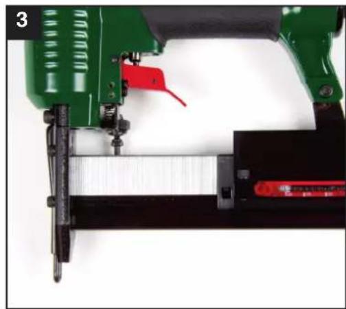
■ Insert the staples as shown in (Fig. 3) or the nails as shown in (Fig. 4).
■ Do not insert more than one complete stick of staples/nails, otherwise the magazine will be overfilled and you will not be able to close it again. Slide the magazine cover forward again until it snaps into place.
■ The level indicator (Fig. 5 / Item F) shows the number of loaded staples / nails if less than 50 are loaded.
7.3 Operation/Operating pressure
■ Connect the pneumatic stapler/nailer to the compressed air connection (Fig. 1 / Item B).
■ Set the swivel air outlet (Fig. 1 / Item K) to the desired position.
■ Before starting the stapler, switch on the compressor and set the operating pressure on the pressure reducer to 4 bar.
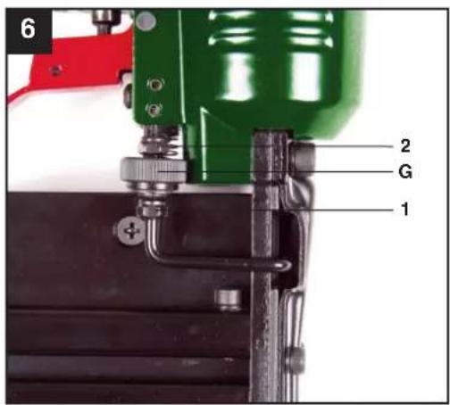
■ The knurled screw (Fig. 6 / Item G) for precision adjustment must be approximately in the middle position between Item 1 and 2. To do so, turn open the knurled screw three revolutions, starting from Position 1.
■ For the purpose of setting the operating pressure it is advisable to use a test workpiece which is similar in structure and material thickness to the workpieces to be joined.
■ To staple/nail, place the pneumatic stapler/nailer against the workpiece and pull the trigger lever (Fig. 1 / Item A) once and
release it again after each shot.
■ If the nail or the staple goes in too deep, reduce the operating pressure on the pressure reducer by 0.5 bar.
■ If the nail or the staple does not go in deep enough or projects, increase the operating pressure on the pressure reducer by 0.5 bar.
■ Place the stapler/nailer against the test workpiece again and fire.
■ Depending on results, keep changing the operating pressure in 0.5 bar increments until the depth that the staples or nails are driven in is roughly correct. For precision adjustment (Para. 7.4), use the knurled screw.
■ The equipment also has an automatic mode. If you keep the trigger lever pressed, the staples/nails will be shot automatically when the pneumatic stapler/nailer is placed against the workpiece.
■ To prevent faults, make sure that you do not staple at the same point twice.
Important:
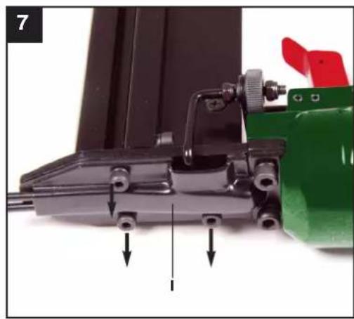
If a staple or nail becomes jammed in the feed shaft, always immediately depressurize the equipment first (remove the compressed air supply hose), open the magazine shaft and only then remove the cover plates (Fig. 8 / Item I/J) by undoing the screws with the supplied Allen keys (Fig. 2 / Item N) (Fig. 7 / 8). Remove the jammed staples, clean the shaft if necessary, and close again in reverse order.
7.4 Precision adjustment
■ The equipment has a depth setting adjuster (Fig. 6 / Item G) in the form of a knurled screw.
■ If you screw it downwards (Fig. 6 / Item 1), the staples/nails will be shot in deeper.
■ If you want to reduce the depth that the staples/nails are shot in, you have to screw the knurled screw upwards (Fig. 6 / Item 2).
Important: To prevent triggering unintentionally, the depth setting must never be pulled back by hand in normal operation.
GB/IE/CY
8. Care and maintenance
Important: Disconnect the equipment from the compressed air system each time before starting to carry out maintenance and cleaning work.
Compliance with the maintenance instructions given here will ensure that this quality product has a long service life and offers failure-free operation.
Before starting work each time, check that the magazine is securely fastened (Fig. 1/Item E). Clean the equipment thoroughly immediately after you have finished the work.
To ensure that your stapler offers lasting perfect service, it requires regular lubrication. Use the supplied oil (Fig. 2 / Item M) for this purpose.
There are two possible means of lubrication:
8.1 By mist oiler
A complete conditioning unit contains a mist oiler and is fitted to the compressor.
8.2 By hand
If your system has neither a conditioning unit or a line oiler, 3-5 drops of oil have to be applied to the compressed air connection each time before the air tool is started up. If the air tool is not used for several days, apply 5-10 drops of oil to the compressed air connection before switching on.
Store your air tool in a dry room only.
8.3 Other maintenance work
There are no parts inside the equipment which require additional maintenance.
9. Cleaning and ordering spare parts
Important: Disconnect the equipment from the compressed air system each time before starting to carry out maintenance and cleaning work.
9.1 Cleaning
■ Keep the trigger catch (Fig. 1/Item H) free of dirt and dust as far as possible. Wipe the equipment with a clean cloth or blow it down with compressed air at low pressure.
■ We recommend that you clean the equipment immediately after you use it.
■ Clean the equipment regularly with a damp cloth and some soft soap. Do not use cleaning agents or solvents; these may be aggressive to the plastic parts in the equipment. Ensure that no water can get into the interior of the equipment.
9.2 Ordering replacement parts
Please provide the following information on all orders for spare parts:
■ Model/type of the equipment
■ Article number of the equipment
■ ID number of the equipment
For our latest prices and information please go to www.isc-gmbh.info
10. Disposal and recycling
The equipment is supplied in packaging to prevent it from being damaged in transit. The raw materials in this packaging can be reused or recycled. The equipment and its accessories are made of various types of material, such as metal and plastic. Defective components must be disposed of as special waste. Ask your dealer or your local council.
11. Excluded from the guarantee are:
■ Wear parts
■ Damage caused by inadmissible operating pressure.
■ Damage caused by compressed air which has not been conditioned.
■ Damage caused by improper use or unauthorized intervention.
12. Declaration of conformity
© explains the following conformity according to EU directives and norms for the following product
Subject to change without notice Wiesenweg 22, D-94405 Landau/Isar
Documents registrar: Siegfried Roider
12. Declaration of conformity
© explains the following conformity according to EU directives and norms for the following product
Noise: measured L_WA = dB(A) ; guaranteed L_WA = dB(A)
P = KW; L/∅ = cm
Notified Body:
2004/26/EC
Emission No.:
Standard references: EN 166
Subject to change without notice Wiesenweg 22, D-94405 Landau/Isar
Documents registrar: Siegfried Roider
13. GUARANTEE CERTIFICATE
Dear Customer,
All of our products undergo strict quality checks to ensure that they reach you in perfect condition. In the unlikely event that your device develops a fault, please contact our service department at the address shown on this guarantee card. Of course, if you would prefer to call us then we are also happy to offer our assistance under the service number printed below. Please note the following terms under which guarantee claims can be made:
- These guarantee terms cover additional guarantee rights and do not affect your statutory warranty rights. We do not charge you for this guarantee.
- Our guarantee only covers problems caused by material or manufacturing defects, and it is restricted to the rectification of these defects or replacement of the device. Please note that our devices have not been designed for use in commercial, trade or industrial applications. Consequently, the guarantee is invalidated if the equipment is used in commercial, trade or industrial applications or for other equivalent activities. The following are also excluded from our guarantee: compensation for transport damage, damage caused by failure to comply with the installation/assembly instructions or damage caused by unprofessional installation, failure to comply with the operating instructions (e.g. connection to the wrong mains voltage or current type), misuse or inappropriate use (such as overloading of the device or use of non-approved tools or accessories), failure to comply with the maintenance and safety regulations, ingress of foreign bodies into the device (e.g. sand, stones or dust), effects of force or external influences (e.g. damage caused by the device being dropped) and normal wear resulting from proper operation of the device. This applies in particular to rechargeable batteries for which we nevertheless issue a guarantee period of 12 months.
The guarantee is rendered null and void if any attempt is made to tamper with the device.
- The guarantee is valid for a period of 3 years starting from the purchase date of the device. Guarantee claims should be submitted before the end of the guarantee period within two weeks of the defect being noticed. No guarantee claims will be accepted after the end of the guarantee period. The original guarantee period remains applicable to the device even if repairs are carried out or parts are replaced. In such cases, the work performed or parts fitted will not result in an extension of the guarantee period, and no new guarantee will become active for the work performed or parts fitted. This also applies when an on-site service is used.
- In order to assert your guarantee claim, please send your defective device postage-free to the address shown below. Please enclose either the original or a copy of your sales receipt or another dated proof of purchase. Please keep your sales receipt in a safe place, as it is your proof of purchase. It would help us if you could describe the nature of the problem in as much detail as possible. If the defect is covered by our guarantee then your device will either be repaired immediately and returned to you, or we will send you a new device.
Of course, we are also happy offer a chargeable repair service for any defects which are not covered by the scope of this guarantee or for units which are no longer covered. To take advantage of this service, please send the device to our service address.
Einhell UK Ltd
Morpeth Wharf
Twelve Quays
Birkenhead, Wirral
CH41 1LF
Tel. 0151 6491500, Fax 0151 6491501
© explains the following conformity according to EU directives and norms for the following product
Subject to change without notice Wiesenweg 22, D-94405 Landau/Isar
Documents registrar: Siegfried Roider
2009/105/EC
2006/95/EC
2006/28/EC
2005/32/EC
2004/108/EC
2004/22/EC
1999/5/EC
97/23/EC
□ 90/396/EC
89/686/EC_96/58/EC
2006/42/EC
Annex IV
Notified Body:
Notified Body No.:
Reg. No.:
Annex V
Annex VI
P = KW; L/∅ = cm
Notified Body:
2004/26/EC
Emission No.:
2000/14/EC_2005/88/EC
Noise: measured L_WA = dB(A) ; guaranteed L_WA = dB(A)
Standard references: EN 166
Subject to change without notice Wiesenweg 22, D-94405 Landau/Isar
Documents registrar: Siegfried Roider
13. TAKUUTODISTUS
Arvoisa asiakas,
© explains the following conformity according to EU directives and norms for the following product
Subject to change without notice Wiesenweg 22, D-94405 Landau/Isar
Documents registrar: Siegfried Roider
2009/105/EC
2006/95/EC
2006/28/EC
2005/32/EC
2004/108/EC
2004/22/EC
1999/5/EC
97/23/EC
□ 90/396/EC
89/686/EC_96/58/EC
2006/42/EC
Annex IV
Notified Body:
Notified Body No.:
Reg. No.:
2000/14/EC_2005/88/EC
Annex V
Annex VI
Noise: measured L_WA = dB(A) ; guaranteed L_WA = dB(A)
P = KW; L/∅ = cm
Notified Body:
2004/26/EC
Emission No.:
Standard references: EN 166
Subject to change without notice Wiesenweg 22, D-94405 Landau/Isar
Documents registrar: Siegfried Roider
13. GARANTIBEVIS
Bästa kund,
Der findes to former for smøring:
© explains the following conformity according to EU directives and norms for the following product
Subject to change without notice Wiesenweg 22, D-94405 Landau/Isar
Documents registrar: Siegfried Roider
© explains the following conformity according to EU directives and norms for the following product
Noise: measured L_WA = dB(A) ; guaranteed L_WA = dB(A)
P = KW; L/∅ = cm
Notified Body:
2004/26/EC
Emission No.:
Standard references: EN 166
Subject to change without notice Wiesenweg 22, D-94405 Landau/Isar
Documents registrar: Siegfried Roider
13. GARANTIBEVIS
Kære kunde!
2009/105/EC
2006/95/EC
2006/28/EC
2005/32/EC
2004/108/EC
2004/22/EC
1999/5/EC
97/23/EC
90/396/EC
89/686/EC_96/58/EC
2006/42/EC
Annex IV
Notified Body:
Notified Body No.:
Reg. No.:
2000/14/EC_2005/88/EC
Annex V
Annex VI
Noise: measured L_WA = dB(A) ; guaranteed L_WA = dB(A)
P = KW; L/∅ = cm
Notified Body:
2004/26/EC
Emission No.:
Standard references: EN 792-13
Subject to change without notice Wiesenweg 22, D-94405 Landau/Isar
Documents registrar: Siegfried Roider
2009/105/EC
2006/95/EC
2006/28/EC
2005/32/EC
2004/108/EC
2004/22/EC
1999/5/EC
97/23/EC
□ 90/396/EC
89/686/EC_96/58/EC
2006/42/EC
Annex IV
Notified Body:
Notified Body No.:
Reg. No.:
2000/14/EC_2005/88/EC
Annex V
Annex VI
Noise: measured L_WA = dB(A) ; guaranteed L_WA = dB(A)
P = KW; L/∅ = cm
Notified Body:
2004/26/EC
Emission No.:
Standard references: EN 166
Subject to change without notice Wiesenweg 22, D-94405 Landau/Isar
Documents registrar: Siegfried Roider
13. ΕΓΓΥΗΣΗ
O Inbusschlüssel 4 mm
ohne Abbildung:
■ je 250 Stück Nägel, 15 mm, 25mm, 40mm, 50mm
■ je 250 Stück Klammern 16 mm, 500 Stück 25 mm, 250 Stück 40 mm
© explains the following conformity according to EU directives and norms for the following product
Subject to change without notice Wiesenweg 22, D-94405 Landau/Isar
Documents registrar: Siegfried Roider
© explains the following conformity according to EU directives and norms for the following product
Noise: measured L_WA = dB(A) ; guaranteed L_WA = dB(A)
P = KW; L/∅ = cm
Notified Body:
2004/26/EC
Emission No.:
Standard references: EN 166
Subject to change without notice Wiesenweg 22, D-94405 Landau/Isar
Documents registrar: Siegfried Roider
13. GARANTIEURKUNDE
natural_image
Pure geometric lines forming a crosshair symbol (no text or labels)


IAN: 49393 PDT 40 A1
Einhell Germany AG
Wiesenweg 22
D-94405 Landau/Isar
Last Information Update · Tietojen tila · Informationsstatus

- AIR NAILER / STAPLER SET
- HÄFT- OCH SPIKPISTOL SET
- DRUCKLUFT-TACKER-SET
- FI
- GB/IE/CY Operation and Safety Notes Page 5
- Table of contents: Page
- Additional safety instructions
- Introduction
- ⚠️ Important.
- Safety Information
- CAUTION
- Read all the safety regulations and
- Keep all safety regulations and instructions in a safe place for future use.
- GB/IE/CY
- Do not lose this safety information.
- Residual risks
- Layout (Fig. 1)
- Items supplied (Fig. 2)
- Not illustrated:
- Intended use
- Remember.
- Technical data
- Reduce noise generation and vibration to a minimum!
- Compressed air quality:
- Air supply:
- Recommended capacity of the compressor:
- Remember:
- Pay attention to the safety regulations.
- Safety goggles (SF026)
- ID number, name and address of the test organization
- Explanation of the symbols on the safety goggles
- Cleaning
- Storage
- Working life
- Transport
- Warnings
- Starting up
- Checking the trigger catch
- Loading staples and nails
- Operation/Operating pressure
- Important:
- Precision adjustment
- Care and maintenance
- There are two possible means of lubrication:
- By mist oiler
- By hand
- Other maintenance work
- Cleaning and ordering spare parts
- Cleaning
- Ordering replacement parts
- Disposal and recycling
- Excluded from the guarantee are:
- Declaration of conformity
- Standard references: EN 166
- GUARANTEE CERTIFICATE
- Dear Customer,
- TAKUUTODISTUS
- Arvoisa asiakas,
- GARANTIBEVIS
- Bästa kund,
- Der findes to former for smøring:
- Kære kunde!
- Standard references: EN 792-13
- ΕΓΓΥΗΣΗ
- ohne Abbildung:
- GARANTIEURKUNDE
Brand : PARKSIDE
Model : PDT 40 A1
Category : Stapler