Concept 1500 - Welding machine Ferm - Free user manual and instructions
Find the device manual for free Concept 1500 Ferm in PDF.


| Product Type | Welding machine |
| Brand | Ferm |
| Model | Concept 1500 |
| Dimensions (W x D x H) | 30 cm x 20 cm x 25 cm |
| Weight | 10 kg |
| Power Supply | 230 V ~ 50 Hz |
| Rated Current | 16 A |
| Welding Current Range | 30 - 150 A |
| Duty Cycle | 60% at 150 A |
| Welding Process | MMA (Manual Metal Arc) |
| Electrode Diameter | 1.6 - 4.0 mm |
| Protection Class | IP21 |
| Insulation Class | H |
| Cooling | Fan cooled |
| Main Functions | Basic MMA welding, adjustable welding current, thermal overload protection |
| Maintenance & Cleaning | Regularly clean ventilation slots, inspect cables for damage, replace worn parts |
| Safety Features | Overheating protection, overload protection, earth leakage protection |
| Spare Parts Availability | Electrode holder, earth clamp, welding cables, contact tips |
| Repairability | Replaceable components; service by qualified technician |
| General Information | Designed for home and hobby use; includes welding shield and chipping hammer |
Frequently Asked Questions - Concept 1500 Ferm
User questions about Concept 1500 Ferm
0 question about this device. Answer the ones you know or ask your own.
Ask a new question about this device
Download the instructions for your Welding machine in PDF format for free! Find your manual Concept 1500 - Ferm and take your electronic device back in hand. On this page are published all the documents necessary for the use of your device. Concept 1500 by Ferm.
USER MANUAL Concept 1500 Ferm
UK Subject to change
Fig.A
natural_image
Pure diagram of six parallel horizontal bars with circular cutouts, no text or symbols presentFig. C

Fig.B
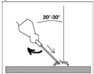
Fig.D
Ferm 47
SPARE PARTS LIST CONCEPT 1500
REF NR DESCRIPTION FERM NR
001 SWITCH(5 CONT. POINTS) 100357
002 THERMAL FUSE 100015
005 GRIP 100009
006 HANDWHEEL + ADJUSTMENT SCREW (23CM) 100010
006 HANDWHEEL + ADJUSTMENT SCREW (26CM) 100011
007PULL RELIEF 101737
010 CURRENT INDICATOR 100003
011 SHUNT 101426
012 SPRING FOR SHUNT 102152
013 BACKPANEL 100008
- SWITCH (4 CONT.POINTS) 100004
- SCALING HAMMER/STEEL WIRE BRUSH 100005
- WELDING GLASS 140500
- WELDING MASK (EXCL. GLASS) 100007

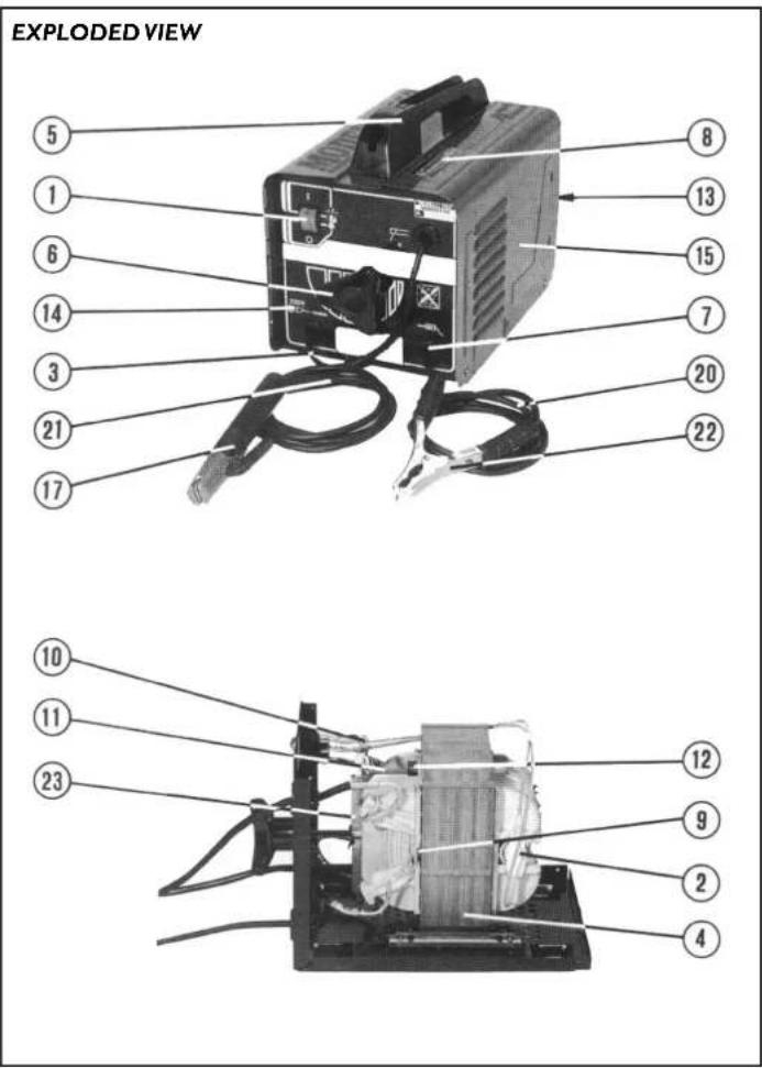
WELDING MACHINE
THE NUMBERS IN THE FOLLOWING TEXT COR-
RESPOND WITH THE PICTURES AT PAGE 2
TECHNICAL SPECIFICATIONS
| Mains voltage | 230V~ |
| Frequency | 50Hz |
| Absorbed power max. | 2.5kVA |
| Welding current | 40-140A |
| No load voltage | 45-48V |
| Usable electrodes | 1.5-3.15mm |
| Weight | 14.0kg |
DESCRIPTION
EN 50060 Standard relative to welders for limited
-
Onephase transformer.
F(W) Power in Watts.
He(Y) No-load voltage.
f(Hz) No-bau voltage in volt. Mains frequency in Herz
12(A) Conventional welding current in ampère.
d(mm) Diameter of electrodes in mm.
nc Number of electrodes starting at room
temperature until thermostat interv
hh Number of weldable electrodes after thermostat intervenes in first hour.
UI(Y) Mains voltage in Volt.
II Max(A) Maximum absorbed current. Value in
ampère of use or automatic switch.
Fuse.
IP21 Protection grade covering.
H Class of isolation of transform.
Thermostat.
Collet.
workcollet. Standardized plus
Standardized plug.
ACCESSORIES AND SPARE PARTS
The following is supplied with your welding machine:
- Manual
- Cables
• Work clamp
- Collet clamp
- Protective mask
- Scalinghammer
- Steelbrush.
Spare parts are available through your local Ferm dealer.
When ordering parts, use the numbers listed in the Parts
List. Parts without an number are not available.
SAFETYINSTRUCTIONS
The following symbols are used in these instructions for use:

Denotes risk of personal injury, loss of life or
damage to the tool in case of non-observance of the
ns in this manual.

Denotes risk of electric shock.
Carefully read this manual before using the machine. Make sure that you know how the machine functions and how to operate it. Maintain the machine in accordance with the instructions to make sure it functions properly. Keep this manual and the enclosed documentation with the machine.
When using electric machines always observe the safety regulations applicable in your country to reduce the risk of fire, electric shock and personal injury. Read the following safety instructions and also the enclosed safety instructions.
SPECIAL SAFETY RULES
- Arc welding produces sparks and fused metal projectiles and fumes: remove all flammable substances and materials from work area.
- Provide adequate ventilation of facilities where welding takes place. Arc welding emits fumes which can be dangerous.
- Do not weld on containers or pipes which hold or have held flammable liquid or gaseous combustibles (danger of explosions and/or fires) or on materials cleaned with chlorinated solvents or on varnished surface (danger of toxic fumes).
• Make sure connection is correct from welder to supply (mains connection). Any electric shock received is potentially lethal. - Avoid stretching the supply cable; unplug before moving machine.
- Keep welding cables, electrode holder and work clamp in good condition; wearing out of isolation and structural parts carrying current is DANGEROUS and results in poor welding quality.
- Avoid direct contact with welding circuit. The no-load voltage between collet and work clamp can be dangerous.
- Do not use the machine in damp or wet places and do not weld in the rain.
• Always protect your eyes with the fitting glasses (grade DIN 9 - 10) equipped with this machine.
• Use gloves and proper protective clothing which are dry and not soiled by oil or grease. - Avoid exposing skin to the ultraviolet rays produced by the arc. The light radiation produced by the arc can damage eyesight and cause burns on the skin.
-
This welder is automatically protected from thermic overheating (thermostat automatic re-start). When the windings reach performance temperature, the protection cuts off the supply circuit. After a few minutes cooling the protection will reopen the supply line. The welder is ready for further use.
-
When you're scaling off the welding slack, protect yourself from the hot iron by using eyeprotection and gloves.
• The workpiece can misform during cooling off. Take care.
IMMEDIATELY SWITCH OFF THE MACHINE IN CASE OF:
- Malfunction of the mainsplug, -socket or damaged cables.
- Broken switch. - Smoke or smell caused by scorched insulation.
MAKE SURE THESE SAFETY RULES ARE NOT BROKEN, OTHERWISE THE GUARANTEE PROVISIONS WILL BE CANCELLED.
ELECTRICAL SAFETY

Always check that the mains voltage corresponds to the voltage on the rating plate.
Replacing cables or plugs
Immediately throw away old cables or plugs when they have been replaced by new ones. It is dangerous to insert the plug of a loose cable in the wall socket.
Connect to the mains cable a standardized plug of adequate capacity to which the yellow/green conductor of the cable is to be connected. Set a standardized plug equipped with fuses or an automatic switch; the correct terminal is to be grounded to the distribution mains. Use fuses of 16 Ampere Slow as a minimum.
Immediately throw away old cables or plugs when they have been replaced by new ones. It is dangerous to insert the plug of a loose cable in the wall outlet.
Using extension cables
Only use an approved extension cable suitable for the power input of the machine. The minimum conductor size is 1.5 mm ^2 . When using a cable reel always unwind the reel completely.
After carrying out all electrical connections necessary both on mains and welding circuits proceed in the following way. Arc welding with an elektric welding machine is a method in which the warmth is delivered by the arc. This arc is made between the electrode and the workpiece.
NB: Before carrying out difficult welds do a practise run, only practice will allow you to obtain a neat and durable weld.
The temperature of the arc is 4000° Celsius what makes the electrode and the workpiece melt. As long as the arc is maintained the electrode will melt and it will supply the material for the connection.
The distance between the electrode and the workpiece must be 1.5 - 4 mm, depending on the diameter of the electrode and the material it is made of. The required welding current is supplied by the welding machine. The required capacity of the welding machine depends on the connections to be made.
THE ELECTRODE
The electrode consists of an iron core with cover. This cover consists partly of irondust. While welding the cover will melt and it will vapor. This way a gas surrounds the welding area protecting the melted iron from oxygen in the air. Some parts of the cover will float on the melted iron (it is of less weight than the iron) and it will protect the iron while cooling off. After cooling this cover can be removed easily by a scaling hammer or steelbrush. Make sure the cover of the electrode is not encapsulated by the iron. This would make an unreliable connection.

Treat the electrodes with caution. The cover can be damaged and this will make the welding very diffi.e sure the electrodes are stored cool and dry.
Choice of the electrode
To make a good connection it is important to choose the right electrode. Also the position in which you have to make the connection, for example above your head, is important while choosing the electrode. A normal electrode can do most ordinary welding jobs.
Electrodes are available in three types:
1. Fast solidification
The cover consists of a lot organic material, which give a good gas protection. It can be used in all kinds of positions, specially for vertical, downgoing connections.
2. Medium solidification
The cover consists of a lot organic material. Good welding in all positions except vertical, downgoing connections. They are useful for vertical, upgoing connections.
3. Slow solidification
The cover is thicker than the other two types and consists less organic material. Thick compact slack. The meltingbath is very thin liquid. Connections most of the time in horizontal direction. For welding aluminium and stainless steel special electrode are available. Ask for advice from your local Ferm-dealer,
PERFORMANCE
The performance of this welder may be expressed by the number of electrodes : nc and nh.
nc: Refers to the number of electrodes which may be welded when the welder commences at room temperature until the thermostat intervenes.
nh: Refers to the AVERAGE VALUE of the number of electrodes which may be welded between re-start and intervention of thermostat, in the first hour of use.
WELDINGCURRENT
By turning the wheel clockwise the current is increased. By turning the wheel counter-clockwise the current is decreased. The value of the current (I2) may be read on the graduated scale on the upper panel and corresponds to the voltage of the arc (U2) according to the equation U2(V)=18 ÷ 0,04 × I2 (EN 50060). When you're using long extension cables, the current is reduced considerably. The required current also depends on the size of the workpiece. Small workpieces require a smaller current.
| Workpiece Electrode core Welding | ||
| thickness (mm2) current(A) | ||
| 2-3 | 2 | 45-65 |
| 4-5 | 2,570-95 | |
| 6-7 | 3,2590-130 | |
| 8-12 | 4130-160 | |
Tab.1
This has a special clamp on the terminal to attach to the exposed part of the electrode.
WORK CABLE
This must be directly connected to the workpiece or the workbench.

Make sure contact to workpiece is adequate by avoiding varnished surfaces and/or non-metallic
PROTECTIVE MASK
Fig.B
This must ALWAYS be used during welding and protects the eyes from the light radiation produced by the arc. The mask allows observation of the welding being carried out.
I. Mask
-
Glass
-
Filter
-
Handgrip

Assemble the welding glass and the cover glass, before you begin to weld.
Never look directly into the arc without the use of a protective mask.
SCALINGHAMMER
With this hammer the slack of the welded connection can be removed. Do not hit too hard, otherwise the connection will be damaged. Always use safety glasses.
STEELBRUSH
With this steelbrush you can remove rust before attaching the work cable to the workpiece or to remove the slack after welding.
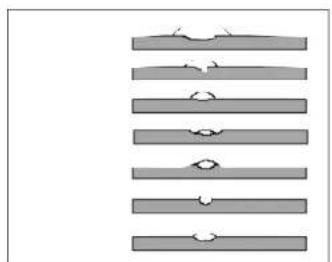
CHARACTERISTICS OF THE WELD SEAM
Fig.C
-
Advancement too low
-
Excessive advancement
-
Arc too short
-
Arc too long
-
Current too low
-
Current too high
-
Current correct
WELDING
Fig.D
- Insert the exposed part of the electrode into the collet and connect the work clamp to the welding piece taking care that electric contact is good.
- Turn on welder and regulate welding current in function of the electrode in use.
- Holding the mask IN FRONT OF FACE stroke the electrode point on the workpiece as if striking a match. This is the most correct method for striking the arc.

difficult.
Don't hit the electrode on the workpiece, which will damage the stick electrode and make arc strike-up
- Immediately after arc strike up try to maintain a distance from the workpiece which is equivalent to the diameter of the electrode used. Maincain this distance as constantly as possible during the weld, remember that the inclination of the electrode to the advancement must be 20^ - 30^ .

Always use pliers to remove consumed electrodes or to move welded pieces.
MALFUNCTION
Below we have listed a number of possible causes and corresponding solutions in case the machine does not function as it should:
When the welding machine doesn't function, check the following
• The thermal fuse is disconnected.
• The fuse is defect (mains).
• The work cable is not connected with the workpiece.
- The collet or work cable or the mains supply is damaged.
MAINTENANCE

Make sure that the machine is not live when carrying out maintenance work on the motor.
The Ferm machines have been designed to operate over a long period of time with a minimum of maintenance. Continuous satisfactory operation depends upon proper machine care and regular cleaning.
Cleaning
Keep the ventilation slots of the machine clean to prevent overheating.
Regularly clean the machine housing with a soft cloth, preferably after each use. Keep the ventilation slots free from dust and dirt.
Faults
Should a fault occur, e.g. after wear of a part, please contact your local Ferm dealer.
In the back of this manual you find an exploded view showing the parts that can be ordered.
ENVIRONMENT
In order to prevent the machine from damage during transport, it is delivered in a sturdy packaging. Most of the packaging materials can be recycled. Take these materials to the appropriate recycling locations.
Take your unwanted machines to your local Ferm-dealer. Here they will be disposed of in an environmen-tally safe way.
The guarantee conditions can be found on the separately enclosed guarantee card.

DECLARATION OF CONFORMITY

We declare under our sole responsibility that this product is in conformity with the following standards or standardized documents
EN50060+Amdt,
EN50199+Amdt
EN60974-1 + Amdt,
in accordance with the regulations:
LDV 73/23 EEC + Amdt
EMC 89/336 + Amdt
from 20-09-2002
GENEMUIDEN NL
W. Kamphol
Quality department


Deutsch
SCHWEIßGERÄT
fra 20-09-2002 GENEMUIDEN NL W. Kamphof Quality department

WARTUNG

ab 20-09-2002 GENEMUIDEN NL W. Kamphof Quality department
NL Nederlands
LASAPPARAAT
DE NUMMERS IN DE NU VOLGENDE TEKST VERWIJZEN NAAR DE AFBEELDINGEN OP PAGINA 2
TECHNISCHE SPECIFICATIES
| Spanning | 230 V~ | |
| Frequentie | 50 Hz |
| Max. vermogen | 2.5 kVA |
| Lasvermogen | 40 - 140 A |
| Ontsteekspanning | 45 - 48 A |
| Elektrodendikte | 1.5 - 3.15 mm |
| Gewicht | |
PRODUKTBESCHRIJVING
- Storing in de netstekker, netsnoer of snoerbeschadiging.
CE ERKLÆRING AVANSVARSFORHOLD (N)
Tendsending | 45-48A
Fachuspachding | 4 Elektsedopskolse
Elekt Vom
11.5-3.15mm
14.0 kg
PRODUKTBESKRIVELSE
CE DÉCLARATION DE CONFORMITÉ (F)
LDV 73/23 EEC + Amdt
EMC 89/336 + Amdt
dès 20-09-2002
GENEMUIDEN NL
W. Kamphof
Quality department

HUOLTO


- SPARE PARTS LIST CONCEPT 1500
- WELDING MACHINE
- ACCESSORIES AND SPARE PARTS
- SAFETYINSTRUCTIONS
- SPECIAL SAFETY RULES
- IMMEDIATELY SWITCH OFF THE MACHINE IN CASE OF:
- MAKE SURE THESE SAFETY RULES ARE NOT BROKEN, OTHERWISE THE GUARANTEE PROVISIONS WILL BE CANCELLED.
- ELECTRICAL SAFETY
- Replacing cables or plugs
- Using extension cables
- THE ELECTRODE
- Choice of the electrode
- Electrodes are available in three types:
- Fast solidification
- Medium solidification
- Slow solidification
- PERFORMANCE
- WELDINGCURRENT
- WORK CABLE
- PROTECTIVE MASK
- Fig.B
- SCALINGHAMMER
- STEELBRUSH
- CHARACTERISTICS OF THE WELD SEAM
- Fig.C
- WELDING
- Fig.D
- MALFUNCTION
- MAINTENANCE
- Cleaning
- Faults
- ENVIRONMENT
- DECLARATION OF CONFORMITY
- Deutsch
- SCHWEIßGERÄT
- WARTUNG
- NL Nederlands
- LASAPPARAAT
- PRODUKTBESCHRIJVING
- CE ERKLÆRING AVANSVARSFORHOLD (N)
- PRODUKTBESKRIVELSE
- CE DÉCLARATION DE CONFORMITÉ (F)
- dès 20-09-2002
- HUOLTO
Brand : Ferm
Model : Concept 1500
Category : Welding machine