
C 10RA - Service après-vente HITACHI - Free user manual and instructions
Find the device manual for free C 10RA HITACHI in PDF.

| Type de produit | Table saw (circular saw) |
| Marque | Hitachi |
| Modèle | C 10RA |
| Dimensions (L × P × H) | 870 mm × 770 mm × 486 mm |
| Poids net | 28 kg |
| Alimentation | 230 V ~, 6.5 A, 1430 W |
| Vitesse à vide | 5000 min⁻¹ |
| Diamètre de la lame | 255 mm |
| Capacité de coupe maximale à 0° | 76 mm |
| Capacité de coupe maximale à 45° | 63 mm |
| Angle de coupe en biseau | Gauche 0° à 45° |
| Accessoires standards | Lame TCT 255 mm, ailes d'extension (2), plaques de fixation (4), clé (2), clé hexagonale (1), coude d'extraction (1), poussoir (1) |
| Dispositifs de sécurité | Protège-lame, couteau diviseur, protection contre les surcharges (bouton de réinitialisation) |
| Entretien | Vérification des charbons, lubrification mensuelle des surfaces coulissantes, nettoyage avec un chiffon humide et savonneux |
| Réparabilité | Utiliser uniquement des pièces de rechange Hitachi d'origine ; réparation par un centre de service agréé |
| Niveau sonore | 106,2 dB(A) |
| Niveau de vibration | 5,5 m/s² |
Frequently Asked Questions - C 10RA HITACHI
User questions about C 10RA HITACHI
0 question about this device. Answer the ones you know or ask your own.
Ask a new question about this device
Download the instructions for your Service après-vente in PDF format for free! Find your manual C 10RA - HITACHI and take your electronic device back in hand. On this page are published all the documents necessary for the use of your device. C 10RA by HITACHI.
USER MANUAL C 10RA HITACHI
natural_image
Line drawing of a Hitachi C10RA machine with no visible text or symbols on the device itselfRead through carefully and understand these instructions before use.
Bruksanvisning
Brugsanvisning
Bruksanvisning
Käyttöohjeet
Handling Instructions
| Svenska | Dansk | Norsk | |
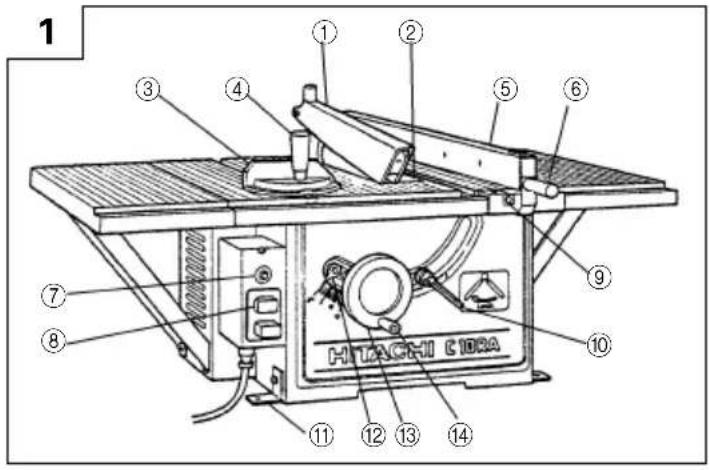
| 1 | Sågklingsskydd | Savklinge-beskytter | Sagbladvern |
| 2 | Bordinsättning | Bord-indsats | Bordinnsats |
| 3 | Geringslikare | Geringslære | Gjæringsmåler |
| 4 | Klämhandtag (B) | Spændehändtag (B) | Klemhändtak (B) |
| 5 | Klyvsågningsstaket | Parallelanslag | Ripevern |
| 6 | Klämhandtag (A) | Spændehändtag (A) | Klemhändtak (A) |
| 7 | Återställningsknapp | Nulstillingsknap | Tilbakestillingsknapp |
| 8 | Startomkopplare | Afbryder | Bryter |
| 9 | Visare | Viser | Viser |
| 10 | Tipplåsningshandtag | Hældningshändtag | Vippelåshendel |
| 11 | Skränkningsplatta (standardtillbehör) | Fastgøringsplade (standardtilbehør) | Festeplate (standardutstyr) |
| 12 | Nålvisare | Visernål | Nåleviser |
| 13 | Inställningsratt | Hjul | Skive |
| 14 | Styrhandtag | Hjulstang | Styre |
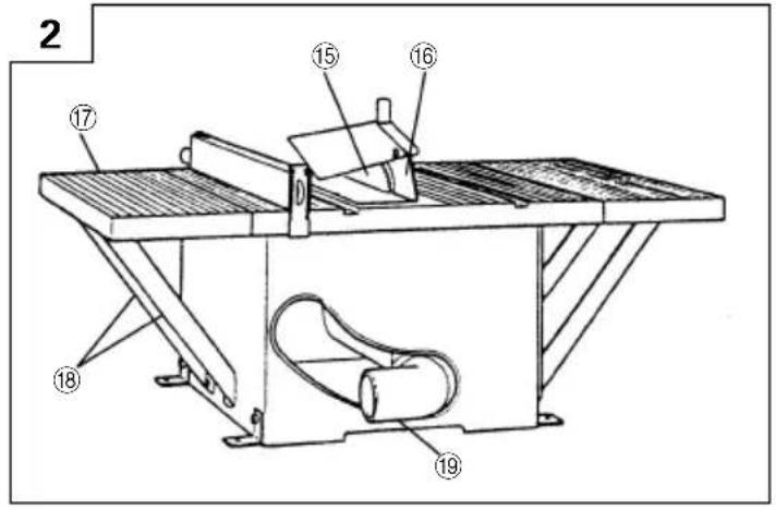
| 15 | Sågklinga | Savklinge | Sagblad |
| 16 | Spaltkniv | Spaltekniv | Spaltekniv |
| 17 | Förlängningsvinge (standardtillbehör) | Bordforlænger (standardtilbehör) | Forlengelsesbrett |
| 18 | Förlängningsstöd | Forlængerstøtte | Forlegelsesstøtte |
| 19 | Knä (standardtillbehör) | Vinkelrør (standardtilbehör) | Rørkne (standardutstyr) |
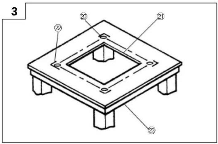
| 20 | 8 mm hål | 8 mm hul | 8 mm hull |
| 21 | Fyrkantig utskärning (mitt) | Kvadratisk udsnit (midte) | Kvadratisk utsnitt (senter) |
| 22 | Skränkningsplattans placeringsmärke | Positionsmarkering for indsatsplade | Lokaliseringsmerke for stilleplate |
| 23 | Arbetsbänk, ställ eller skåp | Bænk, stand eller kabinet | Arbeidsbenk, stativ eller kabinett |
| 24 | Skåra | Rille | Spor |
| 25 | Plåtskena | Pladestang | Emne for tynnplatevalsing |
| 26 | Upp | Op | Opp |
| 27 | Ned | Ned | Ned |
| 28 | Dra åt | Stram | Trekke til |
| 29 | Lossa | Løsn | Løsne |
| 30 | Fäste | Holder | Konsoll |
| 31 | 6 × 16 mm: S bult | 6 × 16 mm bolt | 6 × 16 mm bolt |
| 32 | Fjäderbricka | Fjederskive | Fjærskive |
| 33 | Flatbricka | Flad skive | Flate skive |
| 34 | Mellanlägg | Underlagsskive | Blikkinnlegg |
| 35 | Springa | Spalte | Sliss |
| 36 | 6 mm bult med huvud och fyrkantig hals | 6 mm cylinderskrue med kvadratisk hals | 6 mm hodeskrue med firkantet hals |
| 37 | 6 mm Specialmutter | 6 mm Specialmøtrik | 6 mm Spesialmutter |
| 38 | Flatbricka | Flad skive | Flat skive |
| 39 | Riktskena | Retskinne | Linjal |
| 40 | Under 5 mm | Mindre end 5 mm | Mindre enn 5 mm |
| 41 | Avnötningsgråns | Slidgrænselinie | Slitasjegrenselinje |
| 42 | 6 × 20 mm: S bult | 6 × 20 mm bolt | 6 × 20 mm bolt |
| 43 | 8 × 20 mm: S bult | 8 × 20 mm bolt | 8 × 20 mm bolt |
| 44 | Ben | Fod | Fot |
| 45 | Stag | Stiver | Stag |
| 46 | Bricka | Spændeskive | Pakning |
| 47 | 8 mm bult med huvud och fyrkantig hals | 8 mm cylinderskrue med kvadratisk hals | 8 mm hodeskrue med firkantet hals |
| 48 | Mutter | Møtrik | Mutter |
| 49 | Gummihatt | Gummihætte | Gummihette |
| 50 | Rät vinkel | Ret vinkel | Firkantet |
| 51 | 6 mm maskinskruv (A) | 6 mm maskinskrue (A) | 6 mm maskinskrue (A) |
| 52 | 6 mm maskinskruv (B) | 6 mm maskinskrue (B) | 6 mm maskinskrue (B) |
| 53 | 45°-likare | 45° lære | 45 o måler |
| 54 | 6 mm: S bolt | 6 mm bolt | 6 mm bolt |
| 55 | Staketfäste | Parallelanslag-holder | Vernkonsoll |
| 56 | 5 mm maskinskruv | 5 mm maskinskrue | 5 mm maskinskrue |
| 57 | Skala | Skala | Skala |
| 58 | Vinkelskala | Vinkelskala | Vinkelmåler |
| 59 | Visare | Viser | Viser |
| 60 | 5 mm maskinskruv | 5 mm maskinskrue | 5 mm maskinskrue |
| 61 | Skruvnyckel | Nøgle | Skrunøkkel |
| 62 | Sexkantnyckel | Sekskantnøgle | Sekskannøkkel |
| 63 | Ställmutter | Stillemøtrik | Låsemutter |
| 64 | Förslitningsgräns | Slidgrænselinie | Slitasjegrense |
| 65 | Borsthatt | Børstehætte | Børstehette |
| 66 | Motor | Motor | Motor |
| 67 | Skruvnyckel | Nøgle | Skrunøkkel |
Shinagawa Intercity Tower A, 20th floor 15-1, Konan 2-chome, Minato-ku, Tokyo, Japan
1 februari 2000
T. Oose
Hitachi Koki Co., Ltd.
OBS!
Shinagawa Intercity Tower A, 20th floor 15-1, Konan 2-chome, Minato-ku, Tokyo, Japan
- februar 2000
T. Oose
Hitachi Koki Co., Ltd.
BEMÆRK
VEDLIKEHOLD OG INSPEKSJON
ADVARSEL
Siemensring 34, 47877 Willich, F.R. Germany
Hitachi Koki Co., Ltd.
Shinagawa Intercity Tower A, 20th floor 15-1, Konan 2-chome, Minato-ku, Tokyo, Japan
- februar, 2000
T. Oose
Hitachi Koki Co., Ltd.
MERKNAD
Shinagawa Intercity Tower A, 20th floor 15-1, Konan 2-chome, Minato-ku, Tokyo, Japan
Helmikuun 1. 2000
T. Oose
Hitachi Koki Co., Ltd.
HUOM!
When using power tools basic safety precautions should always be followed to reduce the risk of fire, electric shock and personal injury, including the following.
Read all these instructions before attempting to operate this product and save these instructions.
-
Keep work area clean. Cluttered areas and benches invite injuries.
-
Consider work area environment. Do not expose power tools to rain. Do not use power tools in damp or wet locations. Keep work area well lit.
Do not use tools in the presence of flammable liquids or gases.
Power tools produce sparks during operation. They also spark when switching ON/OFF. Never use power tools in dangerous sites containing lacquer, paint, benzine, thinner, gasoline, gases, adhesive agents, and other materials which are combustible or explosive.
-
Guard against electric shock. Avoid body contact with earthed or grounded surfaces. For example; pipes, radiators, refrigerator enclosures.
-
Keep other persons away. Do not let persons, especially children, not involved in the work touch the tool or the extension cord and keep them away from the work area.
-
Store idle tools. When not in use, tools should be stored in a dry locked-up place, out of reach of children.
-
Do not force the tool. It will do the job better and safer at the rate for which it was intended.
-
Use the right tool. Do not force small tools to do the job of a heavy duty tool. Do not use tools for purposes not intended; for example do not use circular saws to cut tree limbs or logs.
-
Dress properly. Do not wear loose clothing or jewelry. They can be caught in moving parts. Non-skid footwear is recommended when working outdoors. Wear protective hair covering to contain long hair.
-
Use protective equipment. Use safety glasses. Use face or dust mask if cutting operations create dust.
-
Connect dust extraction equipment. If device are provided for the connection of dust extraction and collecting equipment, ensure these are connected and properly used.
-
Do not abuse the cord. Never yank the cord to disconnect it from the receptacle. Keep the cord away from heat, oil and sharp edges.
-
Secure work. Where possible use clamps or a vise to hold the work. It is safer than using your hand.
-
Do not overreach. Keep proper footing and balance at all times.
-
Maintain tools with care. Keep cutting tools sharp and clean for better and safer performance. Follow instructions for lubricating and changing accessories. Inspect tool cords periodically and if damaged have them repaired by an authorized service facility. Inspect extension cords periodically and replace if damaged. Keep handles dry, clean and free from oil and grease.
-
Disconnect tools. When not in use, before servicing and when changing accessories such as blades, bits and cutters, disconnect tools from the power supply.
-
Remove adjusting keys and wrenches. Form the habit of checking to see that keys and adjusting wrenches are removed from the tool before turning it on.
-
Avoid unintentional starting. Do not carry plugged-in tool with finger on switch. Ensure switch is in "off" position when plugging in.
-
Use outdoor extension leads. When the tool is used outdoors, use only extension cords intended for outdoor use and so marked.
-
Stay alert. Watch what you are doing. Use common sense. Do not operate the tool when you are tired.
-
Check damaged parts. Before further use of tool, it should be carefully checked to determine that it will operate properly and perform its intended function. Check for alignment of moving parts, binding of moving parts, breakage of parts, mounting and any other conditions that may affect its operation. A guard or other part that is damaged should be properly repaired or replaced by an authorized service center unless otherwise indicated in this handling instructions. Have defective switches replaced by an authorized service center. Do not use the tool if the switch does not turn it on and off.
-
Do not use power tools for applications other than those specified in the handling instructions.
-
Warning The use of any accessory or attachment other than one recommended in this handling instructions or the HITACHI catalog may present a risk of personal injury.
-
Repairing must be done only by authorized service facility. Manufacturer is not responsible for any damages and injuries due to the repair by the unauthorized persons as well as the mishandling of the tool.
-
Have your tool repaired by a qualified person. This power tool complies with the relevant safety rules. Repairs should only be carried out by qualified persons using original spare parts, otherwise this may result in considerable danger to the user.
-
To ensure the designed operational integrity of power tools, do not remove installed covers or screws.
-
Do not touch movable parts or accessories unless the power source has been disconnected.
-
Use your tool at lower input than specified on the nameplate; otherwise, the finish may be spoiled and working efficiency reduced due to motor overload.
-
Do not wipe plastic parts with solvent. Solvents such as gasoline, thinner, benzine, carbon tetrachloride, alcohol, may damage and crack plastic parts. Do not wipe them with such solvent. Clean plastic parts with a soft cloth lightly dampened with soapy water.
-
Use only original HITACHI replacement parts.
-
This tool should only be disassembled for replacement of carbon brushes.
-
The exploded assembly drawing on this handling instructions should be used only for authorized service facility.
-
Warning Noise can be a health hazard. When the noise level exceeds 85db(A), be sure to wear ear protection.
PRECAUTION FOR TABLE SAW
- Never use the table saw with its saw blade guard locked in the open position.
- Ensure that the saw blade guard moves smoothly.
- Do not use the saw without guards in position.
- Always keep the saw blade sharp.
- Do not use saw blades which are damaged or deformed.
- Use only saw blades recommended by HITACHI.
- Select saw blades in relation to the material to be cut.
- Ensure that the workpiece is free of foreign matter such as nails.
- Replace table insert when worn.
-
Do not use the saw to cut other than wood or similar materials.
-
Connect table saw to a dust collecting device when sawing.
- Always use push-sticks to feed the workpiece past the saw blade.
- Always use and correct adjustment of the riving knife.
-
Always use and correct adjustment of the saw blade guard.
-
Always take care when slotting.
- Start cutting only after motor revolution reaches maximum speed.
- Promptly cut OFF the switch when abnormality observed.
- Shut off power and wait for saw blade to stop before servicing or adjusting tool.
SPECIFICATIONS
| Max. CuttingCapacityHeight | 0° 76 mm | |
| Bevel 45° 63 mm | ||
| Saw Blade Diameter 255 mm | ||
| Bevel Cutting Angle | Left 0° ~ 45° | |
| Input 230V-, 6.5A, 1430 W* | ||
| No-Load Speed 5000/min | ||
| Machine Dimensions (Width × Depth × Height) | 870 mm × 770 mm × 486 mm | |
| Weight (Net) | 28 kg | |
* Be sure to check the nameplate on product as it is subject to change by areas.
STANDARD ACCESSORIES
(1) 255 mm TCT Saw blade (mounted on tool) ..... 1
(2) Extension Wing 2
(3) Set Plate 4
(4) Wrench 2
(5) Hex. Wrench 1
(6) Elbow 1
(7) Push Stick 1
Standard accessories are subject to change without notice.
OPTIONAL ACCESSORIES (sold separately)
(1) Table Saw Stand
Optional accessories are subject to change without notice.
APPLICATION
○Wood (hard or soft woods)
UNPACKING
○Carefully unpack the power tool and all related items (standard accessories).
○Check carefully to make certain all related items (standard accessories) are present.
PRIOR TO OPERATION
- Power source
Ensure that the power source to be utilized conforms to the power requirements specified on the product nameplate. - Power switch
Ensure that the power switch is in the OFF position. - Grounding instructions
This tool is equipped with an electric cord having an equipment-grounding conductor and a grounding
plug. The plug must be plugged into a matching outlet that is properly installed and grounded in accordance with all local codes and ordinances.
Do not modify the plug provided - if it will not fit the outlet, have the proper outlet installed by a qualified electrician.
Improper connection of the equipment-grounding conductor can result in a risk of electric shock.
The conductor with insulation having an outer surface that is green with or without yellow stripes is the equipment-grounding conductor.
If repair or replacement of the electric cord or plug is necessary, do not connect the equipment-grounding conductor to a live terminal.
- Extension cord
When the work area is removed from the power source, use an extension cord of sufficient thickness and rated capacity. The extension cord should be kept as short as practicable.
Use only three-wire extension cords which accept the tool's plug.
Replace or repair damaged or worn cord immediately.
The table saw must be properly secured to a sturdy workbench, stand or cabient.
(1) Secure the four set plates to the saw base at its four corners with four 8 × 20 mm bolts (with/washers) and four 8 mm nuts (Fig. 1).
(2) Place the table saw in the desired location.
Trace hole positions on the four set plates on the workbench, stand or cabinet with a pencil or the like (Fig. 3).
(3) Remove the table saw, and locate a 279 mm or 305 mm square centered between the marks locating the body shell. Cut out and remove the square. This opening allows sawdust to fall out of the body shell (Fig. 3).
(4) Drill a 8 mm hole in each location marked (Fig. 3).
(5) Replace the table saw.
Using suitable length four 50 mm botls, nuts, and flat washers (not provided) secure the table saw to the workbench, cabinet or stand.
ASSEMBLY PROCEDURES
WARNING
To avoid an accident or personal injury, always confirm that the switch is turned OFF and the power plug has been disconnected from the receptacle before assembly of this tool.
1. Assembly of Handle Bar
The handle bar allows faster turning of the wheel.
(1) Tighten the screw of the handle bar until it hits against the wheel.
(2) Securely tighten the handle bar nut with a wrench (Fig. 4).
2. Assembly of Rip Fence CAUTION
○The rip fence must be aligned parallel to the saw blade to minimize the kickback.
The rip fence can be conveniently used to cut a workpiece into different pieces of precise width or into parallel pieces. It can be mounted on either the right or left side of the table.
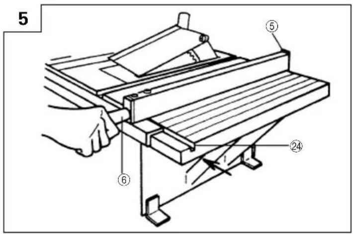
(1) Align the groove in the front of the table with the groove in the fence bracket and slide it in the direction indicated by the arrow from the end of the table (Fig. 5).
(2) Attach clamp handle (A) to the screw of fence bracket.
(3) When moving the rip fence, loosen clamp handle (A) to release the lock. To lock the rip fence, tighten clamp handle (A).
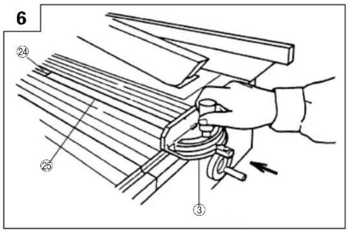
3. Assembly of Miter Gauge
The miter gauge is convenient for cutting long or angular pieces which are difficult to work on with the rip fence.
It can be mounted on either the right or left side of the table.
Align the sheet bar of miter gauge with the table groove and slide it in the direction indicated by the arrow through the front of the table (Fig. 6).
4. Mounting and adjusting Saw Blade Guard CAUTION
○The saw blade guard and riving knife must be aligned properly to the saw blade in order to prevent kickback.
(1) Mounting the riving knife
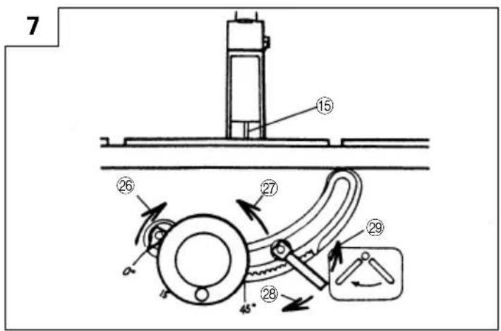
① Turn the wheel fully clockwise and set the saw blade to the maximum cutting height (Fig. 7).
② Loosen the saw blade tilt lock handle and move the saw blade tilting mechanism to the right until it hits against the stopper.
Then tighten the saw blade tilt lock handle.
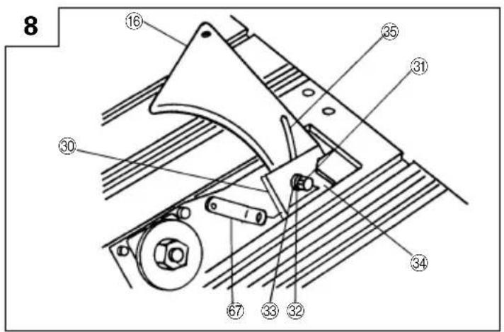
③ Remove the table insert on the table.
④ Mount the riving knife to the bracket using the wrench, 6 × 16 mm bolt, spring washer, flat washer and two shims (Fig. 8).
NOTE
○Make certain the two protrutions are engaged with the slot in the riving knife.
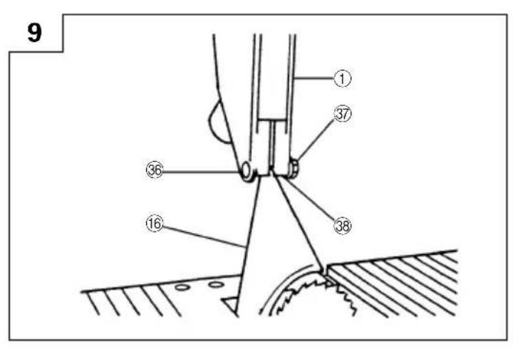
(2) Mounting the saw blade guard
Mount the saw blade guard to the riving knife using the 6 mm Cap Hd. Sq. Neck Bolt, flat washer and 6 mm special nut (Fig. 9).
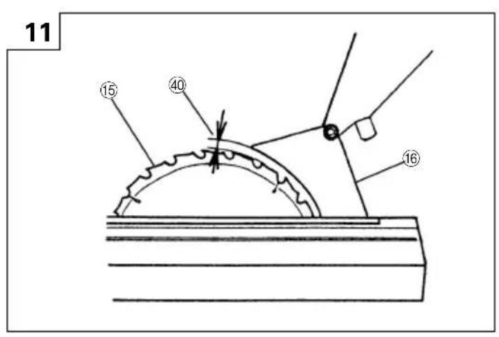
(3) Adjusting the riving knife
① Use a straightedge to align the riving knife with the saw blade (Fig. 10).
NOTE
○The shims can be relocated or be removed as needed to center the riving knife over the saw blade.
② Check clearance between saw blade tip and the riving knife.
It should be less than 5 mm at all positions (Fig. 11).
If not, loosen the 6 × 16 mm bolt securing the riving knife to the bracket.
Move the riving knife up and down. After adjustment of the riving knife is complete, firmly retighten the 6 × 16 mm bolt by wrench.
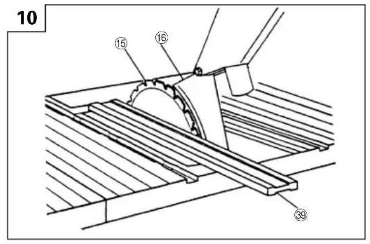
5. Mounting Elbow (Chip Extraction Duct) (Standard Accessory)
Connect a 65 mm hose of dust collector to the chip extraction duct to suck cutting chips away.
Mount the chip extraction duct on the chip discharge outlet at the body rear of the body (Fig. 2).
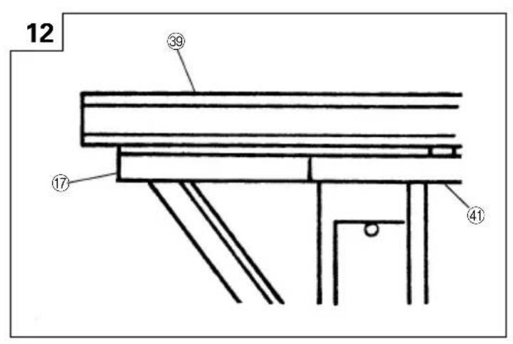
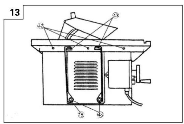
- Assembly of Extension Wings (Standard Accessory)
(1) Use a straightedge to ensure the extension wings are level with the table surface (Fig. 12).
(2) Assembling the extension wings using the three 6 × 20 mm bolts (with/washer) (Fig. 13).
(3) Adjust the tables so that the rip fence receiving groove at the table front is level with the rip fence receiving groove on the extension wings. The extension wings must be the same level as the table. If it is not same level, loosen 6 × 20 mm bolts (with/washer) and readjust the extension wings.
(4) Mount the extension supporter while using the straightedge to make sure that the table surface is level with the surface of extension wings. Tighten the four 8 × 20 mm bolts (Fig. 13).
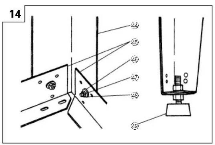
- Assembly of Table Saw Stand (Optional Accessory) Assemble it with the stay and leg(s).
(1) Set the stays below and assemble the legs outside.
(2) Secure with 8 mm cap hd. sq. neck bolts and nuts (Fig. 14).
(3) Then attach rubber caps underneath the legs (Fig. 14).
ADJUSTMENT
This tool is accurately adjusted before shipping from the factory. Check the following accuracies and readjust them if necessary in order to obtain the best results in operation.
WARNING
To avoid an accident or personal injury, always confirm that the switch is turned off and the power plug has been disconnected from the receptacle before adjustment of this tool.
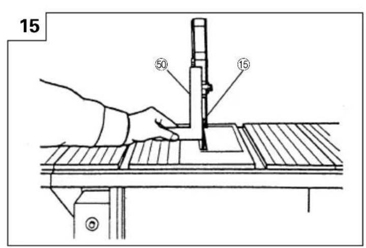
1. Adjusting 90° and 45° positive stops
This tool is equipped with positive stops for rapid and accurate positioning of the saw blade at 90^ and left bevel 45^ to the table. Check and adjust the positive stops by the following procedures.
(1) To adjust positive stop at 90^ .
① Turn the wheel fully clockwise and set the saw blade to the maximum cutting height (Fig. 7).
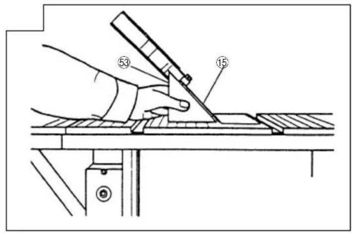
② Use a square to check the saw blade is at a precise 90^ (Fig. 15).
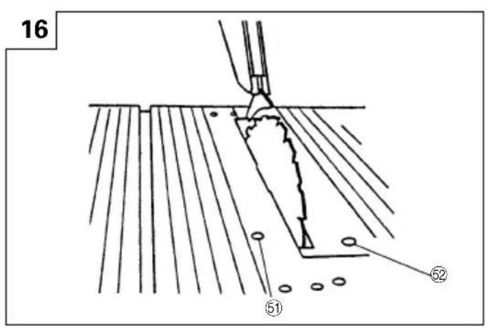
③ If the saw blade is not at a precise 90^ , loosen the 6 mm machine screw (A) a few turns and move the saw blade until the blade is at 90^ to the table (Fig. 16).
④ Loosen the 5 mm machine screw and set the needle pointer to 0°.
(2) To adjust positive stop at left bevel 45°.
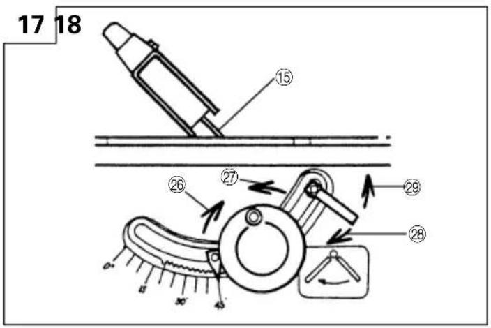
① Turn the wheel fully clockwise and set the saw blade to the maximum cutting height (Fig. 7).
② Loosen the saw blade tilt lock handle and move the saw blade to the left (Fig. 17).
Then tighten the saw blade tilt lock handle.
Use a 45^ gauge to check the saw blade is at a left bevel 45^ (Fig. 18).
If the saw blade is not at a left bevel 45^ , loosen the 6 mm machine screw (B) a few turns and move the saw blade until the blade is at left bevel 45^ to the table (Fig. 16).
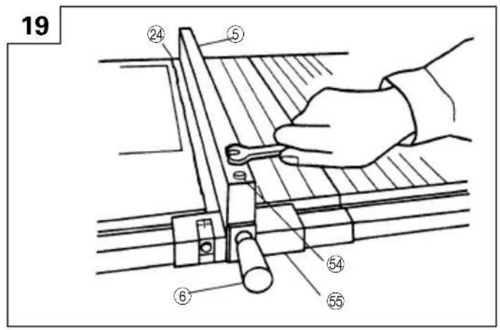
2. Adjustment of rip fence
The edge of the rip fence should then line up parallel with the miter gauge groove.
If the edge of the rip fence is not parallel with the miter gauge groove,
① Loosen the two 6 mm bolts securing the parallel bracket to the fence bracket (Fig. 19).
② Loosen the clamp handle (A), align the rip fence parallel to the groove, and tighten the clamp handle (A).
③ While holding the parallel bracket to prevent movement, tighten the two 6 mm bolts previously loosened.
④ Loosen the clamp handle (A), move and return the parallel bracket adjacent to the groove, tighten the clamp handle (A) and verify that the parallel bracket is parallel to the groove.
⑤ Repeat adjustment until it is parallel.
⑥ After adjustment, tighten two 6 mm bolts.
3. Adjustment of pointer
The pointer should indicate the accurate distance from the saw blade.
NOTE
○The pointer will need to be readjusted whenever a different thickness saw blade is installed.
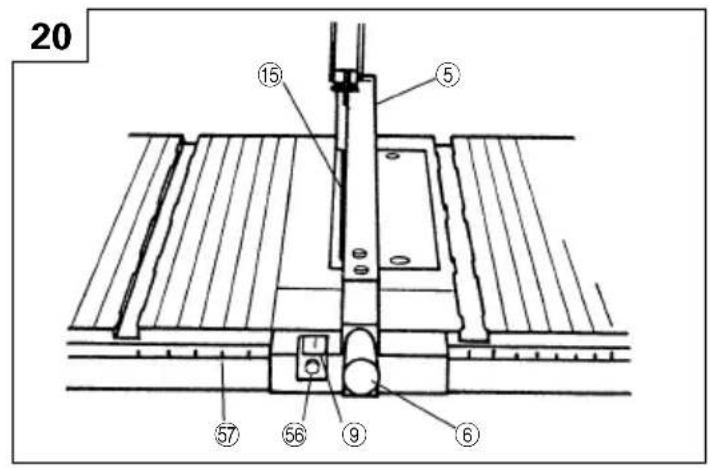
To adjust pointer 0 setting.
(1) Loosen clamp handle (A) and move the rip fence to bring it into tight contact with the side of the saw blade (Fig. 20).
(2) Make sure that the point points to 0 on the scale provided on the table.
(3) If the pointer does not point to 0 on the scale,
① Tighten clamp handle (A).
② Loosen the 5 mm machine screw holding the pointer.
③ Adjust the pointer to the 0 position and retighten the 5 mm machine screw.
4. Adjustment of Miter Gauge
The miter gauge should be squareness to the saw blade.
To adjust pointer 0 setting.
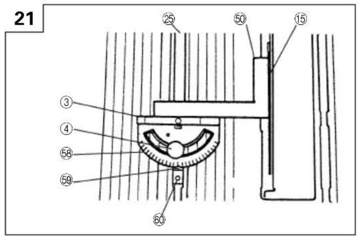
(1) Loosen the clamp handle (B) and place a square against both the saw blade and miter gauge (Fig. 21).
The pointer should indicate 90^ on the protractor scale on the miter gauge.
(2) If the pointer does not point to 0 on the miter gauge, ① Tighten clamp handle (B).
② Loosen the 5 mm machine screw on the sheet bar.
③ Adjust the pointer to the 90^ position and tighten the 5 mm machine screw on the sheet bar.
PRACTICAL APPLICATIONS
1. Switch Operation
To turn the saw on, press the green button. To turn the saw off, press the red button.
2. Overload protective device for motor
When the motor becomes overload, the overload protective device cuts off the current to stop the motor. In this case, push the reset button (after few minute later).
3. Raising and lowering saw blade CAUTION
○Adjust the saw blade height so it is about 3.2 mm above the top of the workpiece.
Raising the saw blade much higher than the workpiece does not make it cut better. It is unsafe and provides less table surface in front of the saw blade.
Never operate while saw blade rotating.
(1) Raising saw blade.
Grasp the wheel and rotate it clockwise to raise the saw blade (Fig. 7).
(2) Lowering saw blade.
Grasp the wheel and rotate it counterclockwise to lower the saw blade (Fig. 7).
4. Saw Blade Tilting Operation WARNING
○The saw tilt lock handle must be locked during all cutting operations.
(1) Loosen saw blade tilt lock handle.
(2) Push in wheel until teeth on hub of hand wheel engage with segment gear.
(3) Turn wheel to tilt the saw blade to the desired angle and tighten saw blade tilt lock handle (Fig. 17).
5. Rip Fence Operation CAUTION
○Make sure that the rip fence is always in parallel with the groove on the table.
(1) Loosen clamp handle (A).
(2) Move the rip fence right and left while pressing the fence bracket against the table surface and set the desired distance from the saw blade (Fig. 5).
(3) Tighten clamp handle (A) to lock the rip fence.
6. Miter Gauge Operation CAUTION
☐For bevel cutting (the saw blade is tilted), use the miter gauge in the right side groove to prevent hands or miter gauge from interfering with the saw blade guard.
(1) Loosen clamp handle (B).
(2) Turning the miter gauge to the desired angle.
(3) Tighten clamp handle (B) to lock the miter gauge (Fig. 21).
OPERATING INSTRUCTIONS
Ripping requires the use of the rip fence and cross cutting uses the miter gauge.
CAUTION
○Always use eye protection when working with the tool to prevent eye injury.
○Also, use a face mask for additional safety and wear a dust mask if the cutting operation produces dust.
1. Ripping
Cutting operation
① Adjust the saw blade height so it is about 3.2 mm above the top of the workpiece.
② Hold the workpiece flat on the table and against the rip fence.
Keep the workpiece about 25 mm away from the saw blade.
CAUTION
○The workpiece must have a straightedge against the rip fence and must not be warped, twisted or bowed.
Keep both hands away from the saw blade and away from the path of the saw blade.
③ Turn on the switch on and allow the saw blade to come up to speed.
④ Keeping the workpiece against the table and rip fence, slowly feed the workpiece rearward all the way through the saw blade. Continue pushing the workpiece until it is clear of the guard and it falls off the rear of the table.
CAUTION
○Do not push the free piece that is cut off, merely guide it.
○When the width of rip 50 mm to 152 mm wide, use a push stick to feed the workpiece. (Push stick is standard accessory)
○When the width of rip is less than 50 mm wide, use an auxiliary guide a push block.
WARNING
○Never operate to pull the workpiece back with the saw blade turning.
2. Bevel Ripping
This operation is the same as ripping except that the bevel angle is set to an angle other than 0^ .
WARNING
○Only work with the workpiece and rip fence on the right side of the saw blade.
3. Cross Cutting
Cutting Operation
① Adjust the saw blade height so it is about 3.2 mm above the top of the workpiece.
② Hold the workpiece firmly against the miter gauge with the path of the saw blade in line with the desired cut distance.
Keep the workpiece about 25 mm away from the saw blade.
CAUTION
Keep both hands away from the saw blade and away from the path of the saw blade.
③ Turn the switch on and allow the saw blade to come up to speed.
④ While keeping the workpiece against the face of the miter gauge, and holding the workpiece flat against the table, slowly push the workpiece through the saw blade.
WARNING
○Never operate to pull the workpiece back with the saw blade turning.
4. Bevel Ripping
Cutting Operation
This operation is the same as cross cutting except that the bevel angle is set to an angle other than 0^ .
WARNING
○Only operate with the workpiece and miter gauge on the right side of the table.
5. Mitering
Cutting Operation
This operation is the same as cross cutting expect that the miter gauge is locked at an angle other than 90^ .
WARNING
○Hold the workpiece firmly against the miter gauge and feed the workpiece slowly into the saw blade to prevent the workpiece from moving.
6. Compound Mitering
Cutting Operation
This is a compound of bevel cross cutting and mitering.
It is infrequently used. Follow the instruction for both bevel cross cutting and mitering.
MOUNTING AND DISMOUNTING SAW BLADE
WARNING
To prevent an accident or personal injury, always turn off the switch and disconnect the power plug from the receptacle before removing or installing a blade.
1. Mounting the saw blade
(1) Turn the wheel fully clockwise and set the saw blade to the maximum cutting height (Fig. 7).
(2) Tighten the saw blade tilt lock handle and lock the saw blade at 90^ .
(3) Remove the table insert on the table.
(4) Mount the washer (A), saw blade and washer (A) in this order on the saw blade spindle. (The saw blade with the teeth pointing down at the front of the table.)
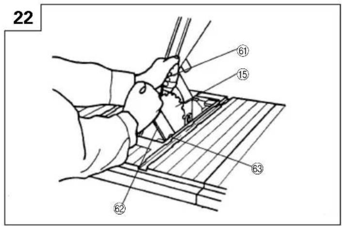
(5) Using the open end wrench and place the wrench on the flats on the saw blade spindle. Hold the saw blade spindle from turning and tighten nut using the remaining wrench (Hex. Wrench) by turning the set nut clockwise (Fig. 22).
(6) Replace the table insert on the table.
WARNING
○Be sure to grip set nut carefully with the wrench. A serious injury can be sustained, if your grip should slip, the wrench come off the nut, and your hand strike the sharp blade edges.
○When mounting the saw blade, confirm that the rotation indicator mark on the saw blade and the rotation direction of the saw are properly matched.
○Tighten the set nut so it does not come loose during operation.
Confirm the set nut has been properly tightened before the power tool is started.
2. Dismounting the saw blade
Dismount the saw blade by reversing the mounting procedures described in paragraph 1 above.
CAUTION
☐Never attempt to install saw blades larger than 255 mm in diameter. Always install saw blades that are 255 mm in diameter or less.
MAINTENANCE AND INSPECTION
WARNING
To avoid an accident or personal injury, always confirm the switch is turned OFF and that the power plug has been disconnected from the receptacle before performing any maintenance or inspection of this tool.
1. Inspecting the saw blade
Since use of a dull saw blade will degrade efficiency and cause possible motor malfunction, sharpen or replace the saw blade as soon as abrasion is noted.
2. Inspecting the mounting screws
Regularly inspect all mounting screws and ensure that they are properly tightened. Should any of the screws be loose, re-tighten them immediately. Failure to do so could result in serious hazard.
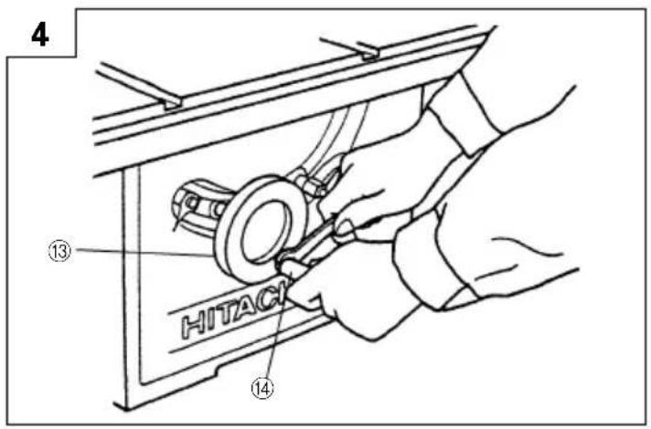
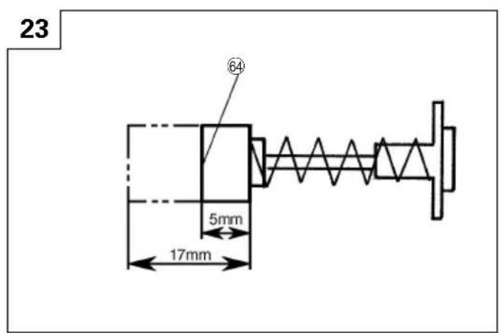
3. Inspecting the carbon brushes (Fig. 23).
The motor employs carbon brushes which are consumable parts. Since an excessively worn carbon brush could result in motor trouble, replace a carbon brush with a new one when it becomes worn to or near the "wear limit". In addition, always keep carbon brushes clean and ensure that they slide freely within the brush holders.
4. Replacing a carbon brushes
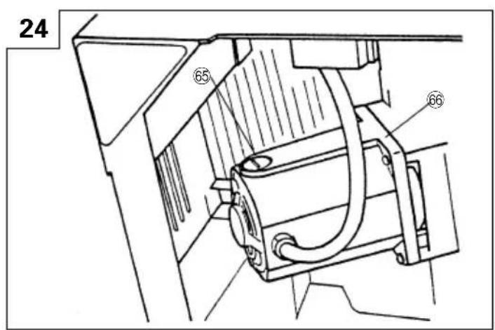
Disassemble the brush cap with a minus-head screwdriver. The carbon brushes can then be easily removed (Fig. 24).
5. Maintenance of the motor
The motor unit winding is the very "heart" of the power tool. Exercise due care to ensure the winding does not become damaged and/or wet with oil or water.
6. Lubrication
Lubricate the following sliding surfaces once a month to keep the power tool in good operating condition for a long time.
Use of machine oil is recommended.
Oil supply points:
* Rotary and moving portion of handle
7. Cleaning
Periodically remove chips and other waste material from the surface of the power tool with a damp, soapy cloth. To avoid a malfunction of the motor, protect it from contact with oil or water.
EC DECLARATION OF CONFORMITY
We declare under our sole responsibility that this product is in conformity with standards or standardized documents EN292, EN60204 and EN55014 in accordance with Council Directives 89/392/EEC, 89/336/EEC and 73/23/EEC.
(1) Serial no.: shown in nameplate
(2) Year of construction: coded in serial no.
(3) Sound power level 106.2 dB (A)
(4) Vibration level 5.5 (m/s ^2 )
Siemensring 34, 47877 Willich, F. R. Germany
Hitachi Koki Co., Ltd.
Shinagawa Intercity Tower A, 20th floor 15-1, Konan
2-chome, Minato-ku, Tokyo, Japan
February 1, 2000
T. Oose
Hitachi Koki Co., Ltd.
NOTE
Due to HITACHI's continuing program of research and development the specifications herein are subject to change without prior notice.
Hitachi Koki Co., Ltd.
001
Code No. H993165-91N
Printed in Taiwan