
C 6DD - Service après-vente HITACHI - Free user manual and instructions
Find the device manual for free C 6DD HITACHI in PDF.

| Product Type | Cordless Circular Saw |
| Brand | Hitachi |
| Model | C6DD |
| Battery Voltage | 18 V |
| Battery Type | Ni-Cd (EB1814, EB18B, EB1820, EB1830H) |
| No-Load Speed | 2600 min⁻¹ |
| Cutting Depth at 90° | 55 mm |
| Cutting Depth at 45° | 40 mm |
| Blade Diameter | 165 mm |
| Blade Arbor | 16 mm or 30 mm |
| Weight (including battery) | 4.4 kg |
| Charger Model | UC24YFA |
| Charging Voltage | 7.2 - 24 V |
| Light Bulb | 12 V, 5 W |
| Electric Brake | Yes |
| Safety Cover | Retractable with lever |
| Riving Knife | Adjustable |
| Cutting Guide | Included (adjustable) |
| Dust Collection | Optional dust collector set |
| Carbon Brushes | Replaceable (Code No. 999058) |
| Warranty | Service by authorized center |
Frequently Asked Questions - C 6DD HITACHI
User questions about C 6DD HITACHI
0 question about this device. Answer the ones you know or ask your own.
Ask a new question about this device
Download the instructions for your Service après-vente in PDF format for free! Find your manual C 6DD - HITACHI and take your electronic device back in hand. On this page are published all the documents necessary for the use of your device. C 6DD by HITACHI.
USER MANUAL C 6DD HITACHI
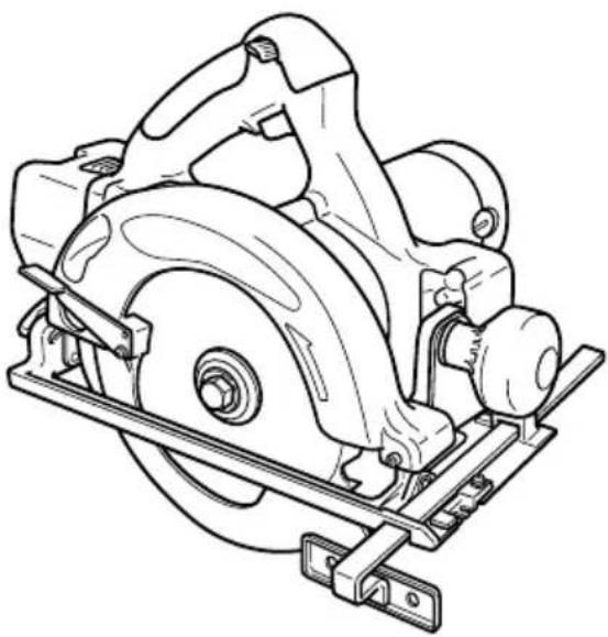
BATTERIDRIVEN CIRKELSÅG BATTERIDREVET RANDSAV BATTERIDREVET SIRKELSAG PARISTOKÄYTTÖINEN SIRKKELISAHA CORDLESS CIRCULAR SAW
C 6DD
natural_image
Technical line drawing of a mechanical assembly with rollers and brackets (no text or symbols)natural_image
Line drawing of a sewing machine on a flat table, labeled with number 1 (no text or symbols on the machine itself)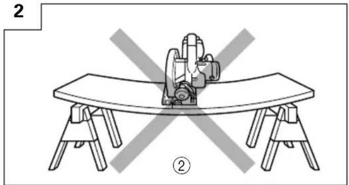
natural_image
Line drawing of a table setup with a curved platform and mechanical components, no text or symbols present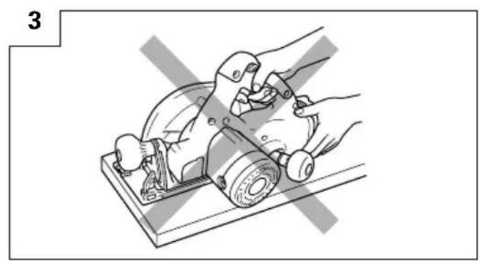
natural_image
Illustration of a hand using a manual tool to cut a mechanical component (no text or symbols visible)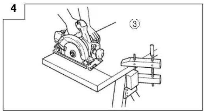
natural_image
Line drawing of a hand operating a manual cutter on a workbench (no text or symbols)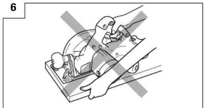
natural_image
Illustration of a hand using a tool to cut or install a mechanical component, no text or symbols present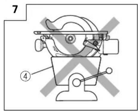
13
14(A)
14(B)
15
16
17
18(A)
18(B)
19 20
| Svenska Dansk Norsk | |||
| 1 | Stöd brådan eller panelen i närheten av skärytan, för att undvika bakslag. panelet nær | For at undgå tilbageslag skal pladen eller snittet understøttes. panelet nær snittetsted | For å unngå tilbakeslag må planken eller det understøttes. |
| 2 | Stöd inte brådan eller panelen långt bort från skärytan. fra snitstedet. fjernt fra snittstedet. | Understøt ikke pladen eller panelet fjernt | Planken eller panelet må ikke understøttes |
| 3 | TYPISK ILLUSTRATION AV KORREKT TYPISK HÄNDSTÖD. HÄNDUNDERSTÖTTELSE HÄNDSTÖTTE | PÅ KORREKT | |
| 4 | Skruvstäd Skruestik Skrustikke | ||
| 5 | Uppladdningsbart batteri Genopladeligt batteri Oppladingsbart batteri | ||
| 6 | Lås | Smæklås Sperrehake | |
| 7 | Namnplåt | Betegnelsesplade | Navneplate |
| 8 | Dra ut | Træk ud | Dra ut |
| 9 | Tryck inåt | Læg i Sett i | |
| 10 | Handtag | Håndtag | Håndtak |
| 11 | Tryck | Tryk | Trykk |
| 12 | Signallampa | Kontrollampe | Pilotlys |
| 13 | Timmer | Emne | Arbeidsstykke av tre |
| 14 | Bottenplatta | Base | Grunnflate |
| 15 | Arbetsbänk | Arbejdsbænk | Arbeidsbenk |
| 16 | Sågblad | Savblad | Sagblad |
| 17 | Gripknopp Håndtagsknop | Knapp | |
| 18 | Spaltkniv | Spaltekniv | Spaltekniv |
| 19 | Bult med sexkanthuvud | Sekskantbolt | Sekskantbolt |
| 20 | Vingbult | Vingebolt | Vingebolt |
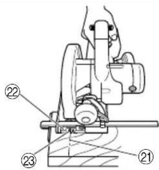
| 21 | Markeringslinje | Markeringslinie | Avmerkingslinje |
| 22 | Bladstyrning | Styrestykke | Styrestykke |
| 23 | Fämre skala när sågbladet inte lutas | Skala foran när ikke vinkelindstillet | Frontskala uten helning |
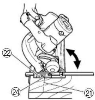
| 24 | Fämre skala vid 45 graders lutning | Skala foran ved indstilling til 45° F | Frontskala ved 45° helning |
| 25 | Skruv M4 | M4-skrue M4 Skrue | |
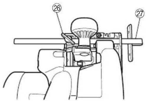
| 26 | Vingbult | Fløjmøtrik Vingebolt | |
| 27 | Styrning (Anslag) | Anslag | Fører |
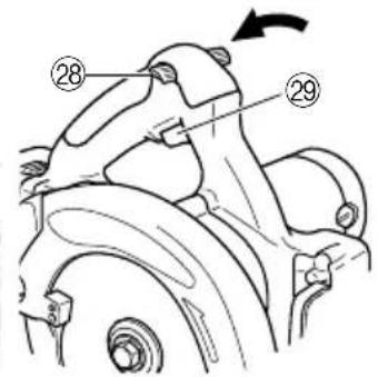
| 28 | Strömbrytarlås | Afbryderlås | Bryterlås |
| 29 | Avtryckare (strömbrytare) | Kontakttrigger | Startbryter |
| 30 | Bult med sexkanthuvud | Sekskantbolt | Sekskantbolt |
| 31 | Låsspak | Låsegreb Sperrespak | |
| 32 | Hylsnyckel Nøgle Fastnøkkel | ||
| 33 | Spak för skyddskåpa | Sikkerhedsdækselarm | Spak for sikkerhetsdeksel |
| 34 | Sågskydd | Savdæksel Sagdeksel | |
| 35 | Mellanlägg (B) | Mellemlægsskive (B) | Underlagsskive (B) |
| 36 | Mellanlägg (A) | Mellemlægsskive (A) Underlagsskive (A) | |
| 37 | Sågspindel | Spindel | Spindel |
| 38 | Lampkåpa | Lampedæksel | Lampedeksel |
| 39 | Konvex | Konveks | Konveks |
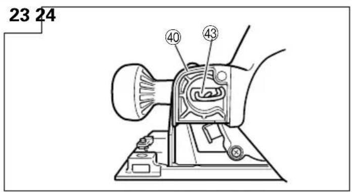
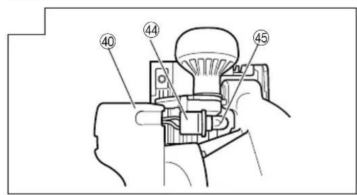
| 40 | Handtagskåpa | Håndtagsdæksel | Håndtaksdeksel |
| 41 | Konkav | Konkav | Konkav |
| 42 | Pilmärkt | Pilemarkering | Pilmerke |
| 43 | Lampfattningens baksida Bagside af fatning Muffens bakside | ||
| 44 | Lampfattning | Fatning | Muffe |
| 45 | Glödlampa | Lyspære | Lyspære |
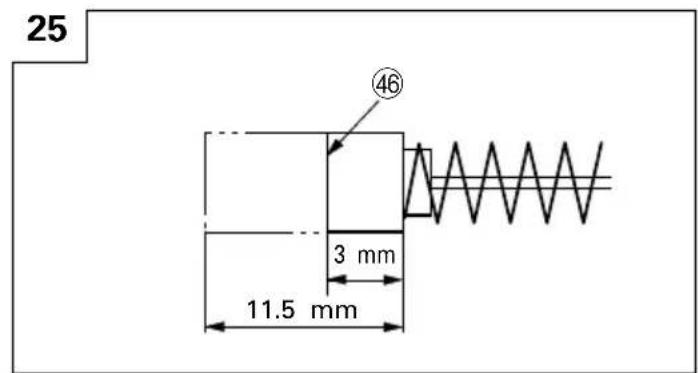
| 46 | Avnötningsgräns | Slidgrænse | Slitasjegrense |
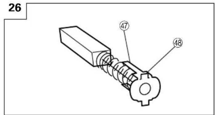
| 47 | Nagel på kolborste | Kulbørstes søm | Stift på kullbørste |
| 48 | Utbuktning på kolborste | Fremspring på kuldørste | Utstikkende del på kullbørsten |
| 49 | Kontaktdel på borstmunstyckets utsida | Kontaktdel på udvendigt børsterør | Kontaktpunkt utenfor børsterøret |
| 50 | Vinkelhake | Vindel | Vinkel |
| 51 | Spårskruv som ställskruv Stilleskrue | Stoppeskrue med spor | |
| 52 | Sågspånssanlarsats | Støroppsamlingsett | Støvsugersæt |
natural_image
Technical line drawing of a mechanical component (no text or symbols)- Sågblad
natural_image
Technical line drawing of a mechanical component with no visible text or symbols- Savblad
natural_image
Technical line drawing of a mechanical component (no text or symbols)- Sagblad
VEDLIKEHOLD OG INSPEKSJON
OBS:
natural_image
Technical line drawing of a mechanical component with no visible text or symbols- Sahanterä
- Keep work area clean. Cluttered areas and benches invite accidents.
- Avoid dangerous environment. Don't expose power tools and charger to rain. Don't use power tools and charger in damp or wet locations. And keep work area well lit. Never use power tools and charger near flammable or explosive materials. Do not use tool and charger in presence of flammable liquids or gases.
- Keep children away. All visitors should be kept safe distance from work area.
- Store idle tools and charger. When not in use, tools and charger should be stored in dry, high or locked-up place-out of reach of children. Store tools and charger in a palce where the temperature is less than 40^ C.
- Don't force tool. It will do the job better and safer at the rate for which it was designed.
- Use right tool. Don't force small tool or attachment to do the job of a heavy duty tool.
- Wear proper apparel. Do not wear clothing or jewelry. They can be caught in moving parts. Rubber gloves and footwear are recommended when working outdoor.
- Use eye protection with most tools. Also use face or dust mask if cutting operation is dusty.
- Don't abuse cord. Never carry charger by cord or yank it to disconnect from receptacle. Keep cord from heat, oil and sharp edges.
- Secure work. Use clamps or a vise to hold work. It's safer than using your hand and it frees both hands to operate tool.
- Don't overreach. Keep proper footing and balance at all times.
- Maintain tools with care. Keep tools sharp at all times, and clean for best and safest performance. Follow instructions for lubricating and changing accessories.
- When the charger is not in use, or when being maintained and inspected, disconnect its power cord from the AC outlet.
- Remove chuck wrenches and wrenches. Form habit of checking to see that wrenches are removed from tool before turning it on.
- Avoid accidental starting. Don't carry tool with finger on switch.
- To avoid danger, always use only the specified charger.
- Use only original HITACHI replacement parts.
- Do not use power tools for applications other than those specified in the Handling Instructions.
- To avoid personal injury, use only the accessories or attachment recommended in these handling instructions or in the HITACHI catalog.
- If the supply cord of this charger is damaged, the charger must be returned to the HITACHI authorized service center for the cord to be replaced. Let only the authorized service center do the repairing. The Manufacturer will not be responsible for any damages or injuries caused by repair by the unauthorized persons or by mishandling of the tool.
- To ensure the designed operational integrity of power tools and charger, do not remove installed covers or screws.
- Always use the charger at the voltage specified on the nameplate.
- Do not touch movable parts or accessories unless the battery has been removed.
- Always charge the battery before use.
-
Never use a battery other than that specified. Do not connect a usual dry cell, a rechargeable battery other than that specified or a car battery to the power tool.
-
Do not use any transformer that has a booster.
- Do not charge the battery from an engine electric generator or DC power supply.
- Always charge indoors. Because the charger and battery heat slightly during charging, charge the battery in a place not exposed to direct sunlight; where the humidity is low and the ventilation good.
- When working in a high place, pay attention to the activities below to make sure there are no people below.
- Use the exploded assembly drawing on this handling instructions only for authorized servicing.
PRECAUTIONS ON USING CORDLESS CIRCULAR SAW
- Always charge the battery at a temperature of 0 – 40°C. A temperature of less than 0°C will result in over charging which is dangerous. The battery cannot be charged at a temperature higher than 40°C.
The most suitable temperature for charging is that of 20 - 25°C. - When one charging is completed, leave the charger for about 15 minutes before the next charging of battery.
Do not charge more than two batteries consecutively. - Do not allow foreign matter to enter the hole for connecting the rechargeable battery.
- Never disassemble the rechargeable battery and charger.
- Never short-circuit the rechargeable battery. Short-circuiting the battery will cause a great electric current and overheat. It results in burn or damage to the battery.
- Do not dispose of the battery in fire. If the battery is burnt, it may explode.
- When using this unit continuously, the unit may overheat, leading to damage in the motor and switch. Please leave it without using it for approximately 15 minutes.
- Do not insert object into the air ventilation slots of the charger. Inserting metal objects or inflammables into the charger air ventilation slots will result in electrical shock hazard or damaged charger.
- Using an exhausted battery will damage the charger.
- Bring the battery to the shop from which it was purchased as soon as the post-charging battery life becomes too short for practical use. Do not dispose of the exhausted battery.
- Wear earplugs to protect your ears during operation.
- Always hold the handle of the power tool firmly. Otherwise the counterforce produced may result in inaccurate and even dangerous operation.
- Do not use saw blades which are deformed or cracked.
- Do not use saw blades made of high speed steel.
- Do not use saw blades which do not comply with the characteristics specified in these instructions.
- Do not stop the saw blades by lateral pressure on the disc.
- Always keep the saw blades sharp.
- Ensure that the safety cover moves smoothly and freely.
- Never use the circular saw with its safety cover fixed in the open position.
-
Ensure that the retraction mechanism of the guard system operates correctly.
-
The saw blades body must be thinner than the riving knife and the width of cut, or kerf (with teeth set) must be greater than the thickness of the riving knife.
- Never operate the circular saw with the saw blade turned upward or the side.
- Ensure that the material is free of foreign matters such as nails.
- The riving knife should always be used except when plunging in the middle of the workpiece.
- The saw blades range should be from 165 mm to 150 mm.
- Be careful of brake kickback.
This circular saw features an electric brake that functions when the switch is released. As there is some kickback when the brake functions, be sure to hold the main body securely.
- Avoid cutting in the state where the base has floated up from the material.
When blade is binding, or when interrupting a cut for any reason, release the trigger and hold the saw motionless in the material until the blade comes to a complete stop. Never attempt to remove the saw from the work or pull the saw backward while the blade is in motion or KICKBACK may occur. Investigate and take corrective actions to eliminate the cause of blade binding.
- Support large panels to minimize the risk of blade pinching and KICKBACK. Large panels tend to sag under their own weight. Supports must be placed under the panel on both sides, near the line of cut and near the edge of the panel as shown in Fig. 1.
To minimize the risk of blade pinching and kickback.
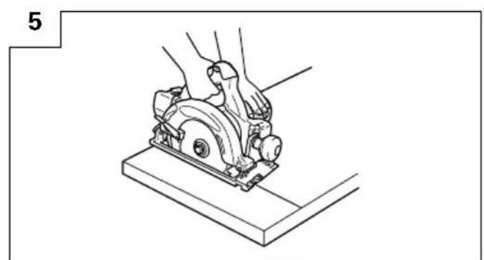
When cutting operation requires the resting of the saw on the work piece, the saw shall be rested on the larger portion and the smaller piece cut off.
- Use extra caution when making a "Pocket Cut" into existing walls or other blind areas. The protruding blade may cut objects that can cause KICKBACK.
NEVER place your hand or fingers behind the saw (Fig. 3). If kickback occurs, the saw could easily jump backwards over your hand, possibly causing severe injury. - WARNING: It is important to support the work piece properly and to hold the saw firmly to prevent loss of control which could cause personal injury. Fig. 4 illustrates typical hand support of the saw.
- Place the wider portion of the saw base on that part of the work piece which is solidly supported, not on the section that will fall off when the cut is made. As examples, Fig. 5 illustrates the RIGHT way to cut off the end of board, and Fig. 6 the WRONG way. If the work piece is short or small, clamp is down.
DON'T TRY TO HOLD SHORT PLACES BY HAND!
-
Never attempt to saw with the circular saw held upside down in a vise. This is extremely dangerous and can lead to serious accidents. (Fig. 7)
-
When the brake becomes ineffective, replace the carbon brushes with new ones.
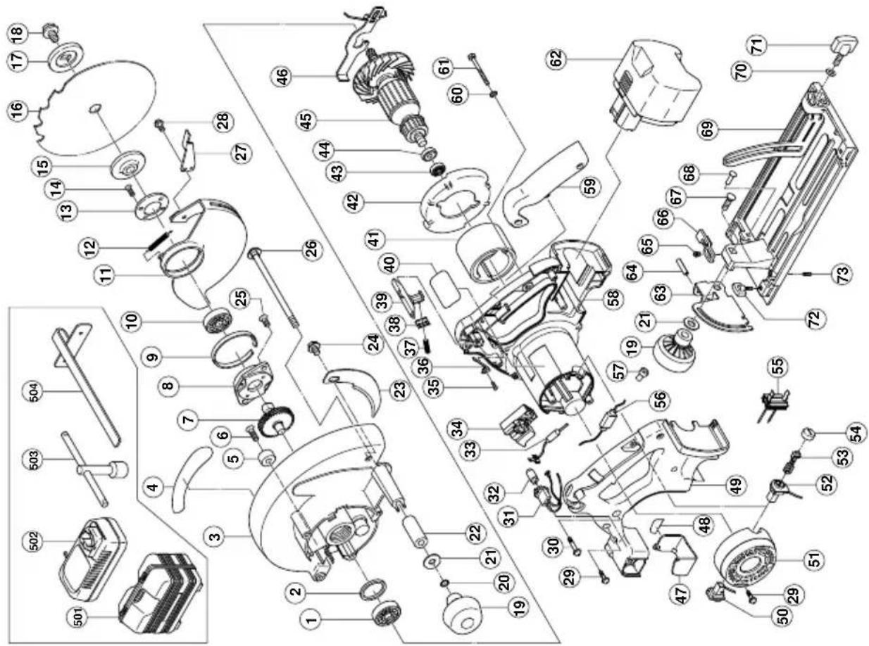
SPECIFICATIONS
POWER TOOL
| Model C6DD | |||
| No-load speed 2600 min | -1 | ||
| Capacity Cutting depth | 90° 55 | mm | |
| 45° 40 | mm | ||
| Rechargeable battery Ni-Cd battery, 18V | |||
| Light bulb 12V, 5W | |||
| Weight 4.4 kg | |||
CHARGER
| Model UC24YFA | |
| Charging voltage 7.2 - 24V | |
| Weight 0.6 kg | |
STANDARD ACCESSORIES
C6DD
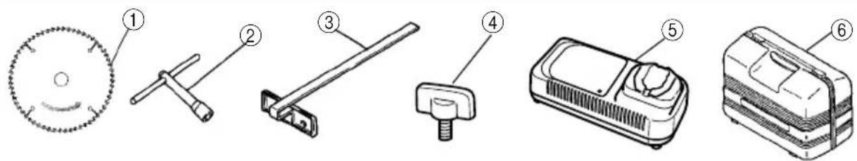
① Saw Blade (mounted on tool) .... 1
② Box Wrench .... 1
③ Guide 1
④ Wing-bolt 1
⑤ Charger (UC24YFA) 1
⑥ Plastic case....1
Standard accessories are subject to change without notice.
OPTIONAL ACCESSORIES (sold separately)
- Battery (EB1814, EB18B, EB1820, EB1830H)
natural_image
Technical line drawing of a mechanical component with no visible text or symbols- Saw Blade
Use.....Cutting various types of wood.
| External Diam | Hole Diam. No. of | Teeth |
| 165 mm 16 | mm 16 pieces | |
| 165 mm 30 | mm 16 pieces |
- Washer (A) .... for 16 mm (Hole dia .of saw blade) .... for 30 mm (Hole dia. of saw blade)
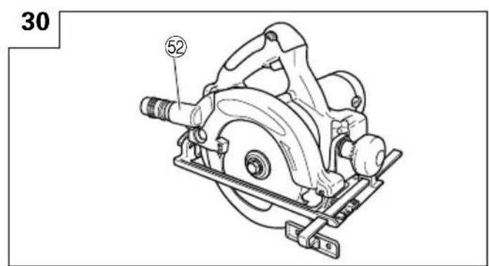
- Dust Collector Set (D)
Connect the suction hose to collect saw dust with the vacuum cleaner (see Fig. 30).
Optional accessories are subject to charge without notice.
APPLICATION
Cutting various types of wood.
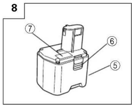
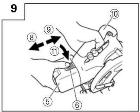
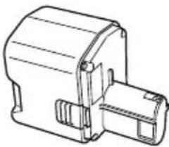
BATTERY REMOVAL/INSTALLATION
- Battery removal
Hold the handle tightly and push the battery latches to remove the battery (see Fig. 8 and 9).
CAUTION
Never short-circuit the battery.
- Battery installation
Insert the battery while observing its polarities (see Fig. 9).
CHARGING
Before using the power tool, charge the battery as follows.
- Connect the charger's power cord to a receptacle. When the power cord is connected, the charger's pilot lamp will blink in red. (At 1-second intervals).
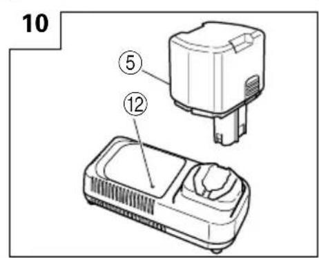
- Insert the battery into the charger.
Firmly insert the battery into the charger till it contacts the bottom of the charger and checking the polarities as shown in Fig. 10.
CAUTION
○If the batteries are inserted in the reverse direction, not only recharging will become impossible, but it may also cause problems in the charger such as a deformed recharging terminal.
3. Charging
When inserting a battery in the charger, charging will commence and the pilot lamp will light continuously in red.
When the battery becomes fully recharged, the pilot lamp will blink in red. (At 1-second intervals.) (See Table 1)
(1) Pilot lamp indication
The indications of the pilot lamp will be as shown in Table 1, according to the condition of the charger or the rechargeable battery.
Table 1
| Indications of the pilot lamp | |||
| Before charging | Blinks (RED) | Lights for 0.5 seconds. Does not light for 0.5 seconds. (off for 0.5 seconds) | |
| While charging | Lights (RED) | Lights continuously | |
| Charging complete | Blinks (RED) | Lights for 0.5 seconds. Does not light for 0.5 seconds. (off for 0.5 seconds) | |
| Charging impossible | Flickers (RED) | Lights for 0.1 seconds. Does not light for 0.1 seconds. (off for 0.1 seconds) | Malfunction in the battery or the charger |
| Charging impossible | Lights (GREEN) | Lights continuously | The battery temperature is high, making recharging impossible. |
(2) Regarding the temperatures of the rechargeable battery.
The temperatures for rechargeable batteries are as shown in the table below, and batteries that have become hot should be cooled for a while before being recharged.
Table 2 Recharging ranges of batteries
| Rechargeable batteries which | Temperatures at the battery can be recharged |
| EB1814. EB18B. EB1820 | -5°C - 60°C |
| EB1830H | 0°C - 45°C |
(3) Regarding recharging time
Depending on the combination of the charger and batteries, the charging time will become as shown in Table 3.
Table 3 Charging time (At 20°C)
| Battery\Charger | UC24YFA |
| EB1814 Approx. 40 min. | |
| EB18B, EB1820 Approx. 50 min. | |
| EB1830H Approx. 70 min. |
NOTE
The charging time may vary according to temperature and power source voltage.
-
Disconnect the charger's power cord from the receptacle.
-
Hold the charger firmly and pull out the battery.
NOTE
After operation, pull out batteries from the charger first, and then keep the batteries properly.
Regarding electric discharge in case of new batteries, etc.
As the internal chemical substance of new batteries and batteries that have not been used for an extended period is not activated, the electric discharge might be low when using them the first and second time. This is a temporary phenomenon, and normal time required for recharging will be restored by recharging the batteries 2 – 3 times.
How to make the batteries perform longer.
(1) Recharge the batteries before they become completely exhausted.
When you feel that the power of the tool becomes weaker, stop using the tool and recharge its battery. If you continue to use the tool and exhaust the electric current, the battery may be damaged and its life will become shorter.
(2) Avoid recharging at high temperatures.
A rechargeable battery will be hot immediately after use. If such a battery is recharged immediately after use, its internal chemical substance will deteriorate, and the battery life will be shortened. Leave the battery and recharge it after it has cooled for a while.
CAUTION
○If the battery is charged while it is heated because it has been left for a long time in a location subject to direct sunlight or because the batetery has just been used, the pilot lamp of the charger lights up green. In such a case, first let the battery cool, then start charging.
When the pilot lamp flickers in red (at 0.2-second intervals), check for and take out any foreign objects in the charger's battery installation hole. If there are no foreign objects, it is probable that the battery or charger is malfunctioning. Take it to your authorized Service Center.
○Since the built-in micro computer takes about 3 seconds to confirm that the battery being charged with UC24YFA is taken out, wait for a minimum of 3 seconds before reinserting it to continue charging.
If the battery is reinserted within 3 seconds, the battery may not be properly charged.
PRIOR TO OPERATION
1. Setting up and checking the work environment
Check if the work environment is suitable by following the precautions.
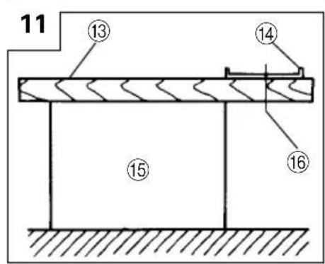
2. Prepare a wooden workbench (Fig. 11)
Since the saw blade will extend beyond the lower surface of the lumber, place the lumber on a workbench when cutting. If a square block is utilized as a workbench, select level ground to ensure it is properly stabilized. An unstable workbench will result in hazardous operation.
CAUTION
To avoid possible accident, always ensure that the portion of lumber remaining after cutting is securely anchored or held in position.
ADJUSTING THE SAW PRIOR TO USE
CAUTION
Pull out battery before doing any adjusting.
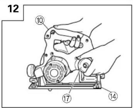
1. Adjusting the cutting depth
As shown in Fig. 12, hold the handle with one hand while loosening the knob with the other.
The cutting depth can be adjusted by moving the base to the desired position. In such manner adjust the cutting depth and then securely retighten the knob.
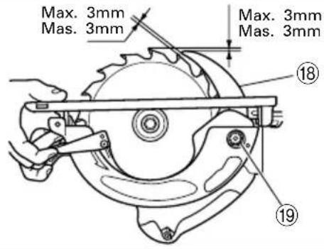
2. Adjusting the riving knife
Loosen the hexagonal - head bolt used to clamp the riving knife, adjust the riving knife to the position shown in Fig. 13 and securely retighten the bolt.
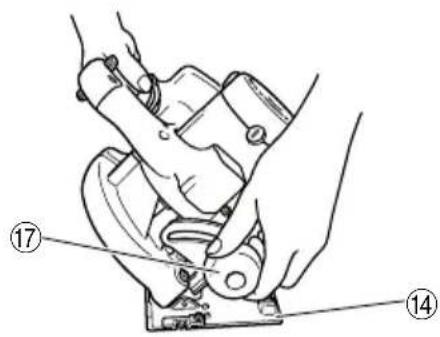
3. Adjusting the angle of inclination
As shown in Fig. 14 (A), Fig. 14 (B) by loosening the knob on the incline gauge and the wing-bolt on the base, the saw blade may be inclined to a maximum angle of 45^ in relation to the base. After having completed the adjustment, reconfirm that the knob and the wing bolt are firmly tightened.
NOTE:
Values of the inclined gauge provided on the base merely serve as a rough guideline. For cutting operation at an inclined posture, use the circular saw after adjusting the angle between the base and the saw blade with a protractor, etc.
4. Adjusting the guide piece
On the circular saw, it is possible to make fine adjustment of the fixing position of the guide piece, where the saw blade and the premarked line are to be aligned.
When the saw is shipped from the factory, the linear portion of a front scale on the guide piece is aligned with the central position of the saw blade. (Fig. 15)
Loosen the fixed screw on the guide piece, should the fixing position be wrong, and make necessary adjustment of the position.
NOTE:
For cutting operation at the inclination of 45 degrees, make adjustment so that the notch on the guide piece and the premarked line become aligned.
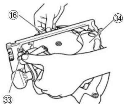
5. Regulating the guide (Fig. 16)
The cutting position can be regulated by moving the guide to the left or right after loosening its wingbolt. The guide may be mounted on either the right or left side of the tool.
HOW TO USE
1. Operation of switch (Fig. 17) (switch trigger and light swi
(1) For safe operation of the machine, a "switch lock" is provided on the side of a handle.
If the "switch trigger" is pulled in a state where "switch lock" is pressed in the direction of the arrow mark, the main switch can be turned ON. And the "switch lock" is used as the "light switch". If the "switch lock (light switch)" is pressed in a state, the light is turned ON.
(2) After the switch is turned ON, even when you release your hand from the switch lock, the body continues running and the light continues being turned ON as long as you keep on pulling the switch trigger.
(3) If you release the switch trigger, you can turn OFF the switch and the "switch lock" returns to the original position automatically and the light turns OFF too.
CAUTION:
○Do not fix and secure the switch lock. Besides, keep your finger off the switch trigger when the circular saw is being carried around. Otherwise, the main body switch can be inadvertently turned ON, resulting in unexpected accidents.
Keep the light ON during cutting operation only. If it is lit ON in other cases, the main body switch can be inadvertently turned ON, resulting in unexpected accidents.
○If the main body is left as it is with the battery inserted, there can be a case where the [switch lock] touches the floor and/or wall surface and lights up continuously, depending on the direction of the body. Be careful, since continuous lighting can easily make a full-charged battery go dead in about 3 hours."
2. Cutting procedures
CAUTION:
○Recheck that the saw blade is securely clamped.
○Confirm that the knob for adjusting the slot depth, the knob and the wing bolt for adjusting the angle of inclination.
(1) Place the base on the material, then align the premarked line and the sawblade with the guide piece front scale section at the front of the base. (Fig. 15)
When the base is not slanted, use the large cutout as the guide. (Fig. 15, Fig. 18(A))
If the base is slanted (45 degrees), use the small front scale as the guide. (Fig. 15, Fig. 18(B))
(2) Ensure that the switch is turned to the ON position before the saw blade comes in contact with the lumber. The switch is turned ON when the trigger is squeezed; and OFF when the trigger is released. Moving the saw straight at a constant speed will produce optimum cutting.
CAUTIONS
Before starting to saw, ensure that the saw blade has reached full speed revolution.
○Should the saw blade be stopped or made an abnormal noise during operation, turn off the switch immediately.
When finished with a job, pull out the battery from the main body.
○Twisting and forcibly pressing the saw during cutting can result in unreasonable pressure on the motor, so try to go straight quietly.
○In the situation where the circular saw is continuously operated while replacing the battery with stocked spare batteries one after another, the motor tends to overheat. Therefore, whenever the housing becomes hot, give the saw a break for a while.
○Avoid cutting operation in a state where the base bottom is afloat from the material being cut. Otherwise, the motor can get locked.
MOUNTING AND DISMOUNTING THE SAW BLADE
CAUTION
To avoid serious accident, ensure the switch is in the OFF position, and pull out the battery.
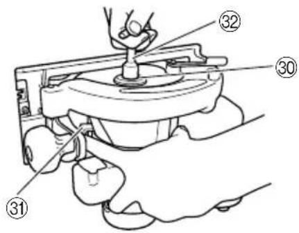
1. Dismounting the saw blade
(1) Set the cutting volume at maximum, and place the Circular Saw as shown in Fig. 19.
(2) Depress the lock lever, lock the spindle, and remove the hexagonal-head bolt and washer (B) with the box wrench.
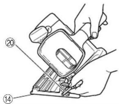
(3) While holding the safety cover lever to keep the safety cover fully retracted into the saw cover, remove the saw blade. (Fig. 20)
2. Mounting the Saw Blade:
CAUTION:
If the bolt is worked using other tools than the provided box wrench, excessive tightening and insufficient tightening may take place resulting in injury.
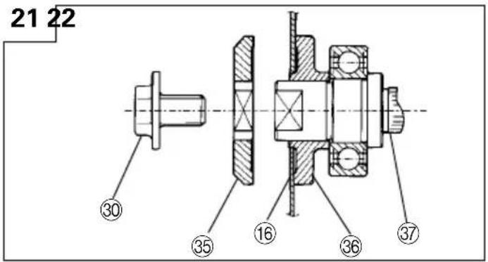
(1) Thoroughly remove any sawdust which has accumulated on the spindle, bolt and washers.
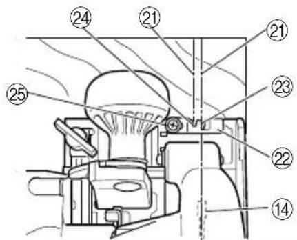
(2) As shown in Fig. 21, the side of Washer (A) with a projected center the same diameter as the inner diameter of the saw blade and the concave side of Washer (B) must be fitted to the saw blade sides.
* Washer (A) is supplied for 2 types of saw blades with the hole diameters of 16 mm and 30 mm. (When buying the Circular Saw, one type of washer (A) is applied.) In case the hole diameter of your saw blade does not correspond to that of washer (A), please contact the shop where you purchased the Circular Saw.
(3) To assure proper rotation direction of the saw blade, the arrow direction on the saw blade must coincide with the arrow direction on the saw cover.
(4) Using the fingers, tighten the hexagonal-head bolt retaining the saw blade as much as possible. Then depress the lock lever, lock the spindle, and thoroughly tighten the hexagonal-head bolt.
CAUTION
After having attached the saw blade, reconfirm that the lock lever is firmly secured in the prescribed position.
REPLACING LIGHT BULB
CAUTION:
○Make absolutely sure that the battery is removed from the main body before replacing the light bulb.
○Immediately after the light is turned OFF, the bulb retains high temperature. Make sure to cool down the light bulb thoroughly before replacing it so as to prevent burns.
○When replacing the light bulb, check the shape of base as well as the rating (12 V, 5 W), and then carry out perfect mounting. Otherwise, the light bulb can come off and/or cause overheat.
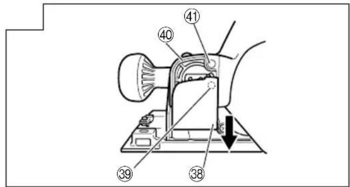
1. Detaching light bulb
(1) Remove the convex part of the light cover from the concave part of the handle cover, and then pull out the light cover in the arrow-marked direction as shown in Fig. 22.
(2) Push the back of the socket, and remove the socket and the light bulb together from the handle cover (Fig. 23).
(3) Remove the light bulb from the socket. (Fig. 24).
2. Attaching light bulb
Take procedures here that are contrary to the detaching procedures.
NOTE:
○When attaching the light bulb to the socket, insert the light bulb until it lightly bumps against the socket.
When attaching the socket to the handle cover, align the socket with the hole of housing while watching the back of the socket shown in Fig. 24, and insert the socket until it lightly bumps against the handle cover.
MAINTENANCE AND INSPECTION
CAUTION:
Pull out battery before doing any inspection or maintenance.
1. Inspecting the saw blade:
Since use of a dull saw blade will degrade efficiency and cause possible motor malfunction, sharpen or replace the saw blade as soon as abrasion is noted.
CAUTION:
If a dull saw blade is used, reactive force is increased during cutting operation. Avoid the use of the dull saw blade without repair.
2. Inspecting the mounting screws:
Regularly inspect all mounting screws and ensure that they are properly tightened. Should any of the screws be loose, retighten them immediately. Failure to do so could result in serious hazard.
3. Maintenance of the motor
The motor unit winding is the very "heart" of the power tool. Exercise due care to ensure the winding does not become damaged and/or wet with oil or water.
4. Inspecting the carbon brushes (Fig. 25)
The motor employs carbon brushes which are consumable parts. Since and excessively worn carbon brush can result in motor trouble, replace the carbon brush with new ones when it becomes worn to or near the "wear limit". In addition, always keep carbon brushes clean and ensure that they slide freely within the brush holders.
NOTE:
When replacing the carbon brush with a new one, be sure to use the Hitachi Carbon Brush Code No. 999058.
5. Replacing carbon brushes
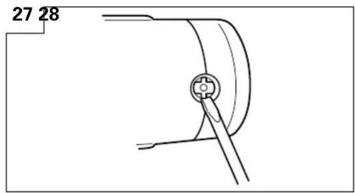
Take out the carbon brush by first removing the brush cap and then hooking the protrusion of the carbon brush with a flat head screw driver, etc., as shown in Fig. 27.
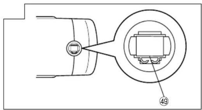
When installing the carbon brush, choose the direction so that the nail of the carbon brush agrees with the contact portion outside the brush tube. Then push it in with a finger as illustrated in Fig. 28. Lastly, install the brush cap.
CAUTION:
Be absolutely sure to insert the nail of the carbon brush into the contact portion outside the brush tube. (You can insert whichever one of the two nails provided.)
Caution must be exercised since any error in this operation can result in the deformed nail of the carbon brush and may cause motor trouble at an early stage.
6. Performance checkup and maintenance of safety cover
Keep the safety cover in good shape for smooth performance at all times. Be sure to make prompt repair in case of any malfunction.
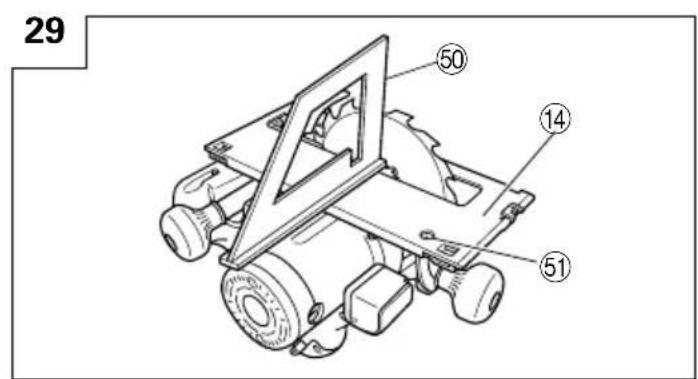
7. Adjusting the base and saw blade to maintain perpendicularity:
The angle between the base and the saw blade has been adjusted to 90^ , however should this perpendicularity be lost for some reason, adjust in the following manner:
(1) Turn the base face up (Fig. 29) and loosen the knob and wing-nut.
(2) Apply a square to the base and the saw blade and turning the slotted set screw with a slotted-head screwdriver, shift the position of the base to produce the desired right angle.
8. Check for dust
Dust may be removed with a clean rag or a cloth dampened with soapy water.
Do not use bleach, chlorine, gasoline or thinner, for they may damage the plastics.
9. Storage
Storing in a place below 40^ C and out of the reach of children.
10. Service and repairs
All quality power tools will eventually require servicing or replacement of parts because of wear from normal use. To assure that only genuine replacement parts must be used, all service and repairs must be performed by a HITACHI AUTHORIZED SERVICE CENTER, ONLY.
11. Service parts list
A: Item No.
B: Code No.
C: No. Used
D: Remarks
CAUTION
Repair, modification and inspection of Hitachi Power Tools must be carried out by an Hitachi Authorized Service Center.
This Parts List will be helpful it presented with the tool to the Hitachi Authorized Serivde Center when requesting repair or other maintenance.
In the operation and maintenance of power tools, the safety regulations and standards prescribed in each country must be observed.
MODIFICATIONS:
Hitachi Power Tools are constantly being improved and modified to incorporate the latest technological advancements.
Accordingly, some parts (i.e. code numbers and/or design) may be changed without prior notice.
NOTE
Due to HITACHI's continuing program of research and development, the specifications herein are subject to change without prior notice.
Information concerning airborne noise and vibration The measured values were determined according to EN50144.
The typical A-weighted sound pressure level: 96 dB (A)
The typical A-weighted sound power level: 109 dB (A)
Wear ear protection.
The typical weighted root mean square acceleration value does not exceed 2.5 m/s^2 .
| A B C D | A B C D |
| 1 600-1VV 1 6001VVCMPS2L | 39 319-904 1 |
| 2 958-130 1 | 40 - - - - 1 |
| 3 302-742 1 "2, 5, 6" | 41 319-820 1 |
| 4 - - - - 1 | 42 302-454 1 |
| 5 961-729 1 | 43 608-VVM 1 608VVC2PS2L |
| 6 949-794 2 M6x20 | 44 311-435 1 |
| 7 319-829 1 | 45 360-554 1 "1, 43, 44" |
| 8 302-433 1 | 46 302-453 1 |
| 9 961-807 1 | 47 319-834 1 |
| 10 600-3VV 1 6003VVCMPS2L | 48 - - - - 1 |
| 11 302-461 1 | 49 319-819 1 |
| 12 302-463 1 | 50 319-828 1 |
| 13 302-435 1 | 51 319-832 1 |
| 14 990-430 2 M4x10 | 52 319-827 1 |
| 15 1 302-476 1 D30 | 53 999-058 2 |
| 15 2 302-443 1 D16 | 54 319-833 2 |
| 16 1 302-409 1 165MM-D30 | 55 319-821 1 |
| 16 2 302-407 1 165MM-D16 | 56 319-826 1 |
| 17 302-423 1 | 57 959-141 1 |
| 18 302-427 1 M8x15.5 | 58 319-818 1 |
| 19 302-458 2 | 59 319-831 1 |
| 20 676-531 1 | 60 962-569 2 |
| 21 949-433 2 | 61 960-108 2 D4x60 |
| 22 319-830 1 | 62 1 319-835 1 EB1820 |
| 23 303-838 1 | 62 2 319-765 1 EB1830H |
| 24 302-468 1 M8x10 | 63 308-479 1 |
| 25 992-013 2 M5x14 | 64 949-686 1 D6x40 |
| 26 303-800 1 M8 | 65 317-200 1 M4x8 |
| 27 302-464 1 | 66 316-246 1 |
| 28 304-043 1 M4x10 | 67 302-457 1 M8x30 |
| 29 302-086 8 D4x20 | 68 308-480 2 D6x17 |
| 30 997-234 3 M5x35 | 69 316-443 1 "19, 21, 63, 65-68, |
| 31 319-820 1 | |
| 32 319-822 1 | 70 949-425 1 M6 |
| 33 319-824 1 | 71 302-459 1 M6x17 |
| 34 319-825 1 | 72 301-806 1 |
| 35 958-715 1 D4x10 | 73 302-469 1 M6x6 |
| 36 319-823 1 | 501 319-836 1 |
| 37 301-631 1 | 502 UC24YFA 1 |
| 38 317-207 1 | 503 302-478 1 13MM |
| 504 302-756 1 |
natural_image
Line drawing of a quill pen in an inkwell (no text or symbols)
natural_image
Line drawing of a quill pen in an inkwell (no text or symbols)
natural_image
Line drawing of a quill pen in an inkwell (no text or symbols)| Svenska | Suomi | ||
| EF-DEKLARATION BETRÄFFANDE LIKFORMIGHETVi tillkännagiver med eget ansvar att denna produkt överensstämmer med standard eller standardiserat dokument EN50144, HD400 och/eller EN55014-2 i enlighet med råddirektiven 89/336/E∅S och/eller 98/37/E∅S.* Denna deklaration gäller för CE-märkningen på produkten. | EY-ILMOITUS YHDENMUKAISUUDESTAYksinomaisella vastuudella vakuutamme, että tämä tuote vastaa normeja tai normitettuja dokumentteja EN50144, HD400 ja/tai EN55014-2 yhteisön ohjeiden 89/336/ETY ja/tai 98/37/ETY mukaisesti.* Tämä ilmoitus sovelletaan tuotekohtaiseen CE-merkintään. | ||
| Dansk | English | ||
| EF-DEKLARATION OM ENSARTETHEDVi eklærer os fuldstændige ansvarlige for, at dette produkt modsvarer gældende standard eller de standardiserede dokumenter EN50144, HD400 og/eller EN55014-2 i overensstemmelse med EF-direktiver 89/336/E∅F og/eller 98/37/E∅F.* Denne erklæring gælder produkter, der er mærket med CE. | EC DECLARATION OF CONFORMITYWe declare under our sole responsibility that this product is in conformity with standards or standardized documents EN50144, HD400 and/or EN55014-2 in accordance with Council Directives 89/336/EEC and/or 98/37/EEC.* This declaration is applicable to the product affixed CE marking. | ||
| Norsk | |||
| EF's ERKLÆRING OM OVERENSSTEMMELSEVierklærerherved at vi påtar oss eneansvaret for at dette produktet er i overensstermmelse med normer eller standardiserte dokumenter EN 50144, HD400 og/eller EN55014-2 i samsvar med Rådsdirektiver 89/336/E∅S og/eller 98/37/E∅S.* Denne erklæringen gjelder produktets påklistrede CE-merking. | |||
| Hitachi Power Tools Europe GmbHSiemensring 34, 47877 Willich, F. R. GermanyHitachi Koki Co., Ltd.Shinagawa Intercity Tower A, 15-1, Konan 2-chomeMinato-ku, Tokyo, Japan | CE01J. HiranoY. Hirano | ||