
CG 27EJ - Lawn mower HITACHI - Free user manual and instructions
Find the device manual for free CG 27EJ HITACHI in PDF.

| Product Type | Lawn Mower |
| Brand | Hitachi |
| Model | CG 27EJ |
| Engine Type | 2-stroke, 27 cm³ |
| Fuel Type | Gasoline-oil mixture (ratio 25:1 to 50:1) |
| Fuel Tank Capacity | 0.67 L |
| Spark Plug | CHAMPION RCJ8Y or equivalent |
| Dry Weight | Approximately 5.4 kg |
| Sound Power Level (LwA) | 116 dB(A) |
| Cutting Tool Type | Cutting blade (Ø25.4 mm) or Brain cutting head |
| Idle Speed | 2,500 - 3,000 rpm |
| Recommended Working Speed | > 6,500 rpm |
| Initial Line Length (manual head) | 17 cm |
| Safety Harness | Included |
| Blade Guard | Included |
| Anti-vibration System | Yes, on handles |
| Routine Maintenance | Air filter cleaning, spark plug check, angle drive greasing |
| Required Safety Equipment | Safety glasses, gloves, hearing protection, non-slip shoes |
| Safety Distance | 15 m from people |
| Recommended Spare Parts | Blade, spark plug, air filter, fuel filter (Hitachi original) |
Frequently Asked Questions - CG 27EJ HITACHI
User questions about CG 27EJ HITACHI
0 question about this device. Answer the ones you know or ask your own.
Ask a new question about this device
Download the instructions for your Lawn mower in PDF format for free! Find your manual CG 27EJ - HITACHI and take your electronic device back in hand. On this page are published all the documents necessary for the use of your device. CG 27EJ by HITACHI.
USER MANUAL CG 27EJ HITACHI
Grass Trimmer/Brush Cutter Rasentrimmer/Motorsense Coupe- Herbes/ Débroussailleuse Bordatore/Decespugliatore Motor Zeis/Motor bosmaaier
Motoguadañas/Desbrozadoras Foice a motor/Roçadora Grästrimmer/Röjsax Græstrimmer/Buskrydder Gresstrimmer/Buskrydder Trimmeri/Raivaussaha
CG 27EJ (S)/CG 27EJ (SL)/CG 27EJ (SLD)/ CG 27EJ (SP)/CG 27EJ (SLP)/CG 27EJ (SLDP)/ CG 28EJ/CG 28EJ (L)/CG 28EJ (SL)/CG 33EJ/ CG 33EJ (L)/CG 33EJ (S)/CG 33EJ (SL)
natural_image
Technical line drawing of a mechanical assembly with no visible text or symbols
Read the manual carefully before operating this machine. Lesen Sie vor der Verwendung diese Anleitung sorgfältig durch. Lire attentivement le manuel avant d'utiliser la machine. Leggere attentamente il manuale prima di mettere in funzione questa apparecchiatura. Lees de handleiding zorgvuldig door voordat u de machine bedient. Antes de utilizar esta máquina, lea cuidadosamente el manual. Leia o manual atentamente antes de operar esta máquina. Läs noga igenom bruksanvisningen innan maskinen tas i bruk. Læs denne brugsvejledning omhyggeligt, inden maskinen tages i brug. Bruksanvisningen må leses nøye før bruk av maskinen. Lue ohjekirja huolellisesti ennen koneen käyttämistä.
Handling instructions Bedienungsanleitung Mode d'emploi Istruzioni per l'uso Gebruiksaanwijzing Instrucciones de manejo
Instruções de uso Bruksanvisning Brugsanvisning Bruksanvisning Käyttöohjeet
natural_image
Technical line drawing of a mechanical assembly with a motor and housing (no text or symbols)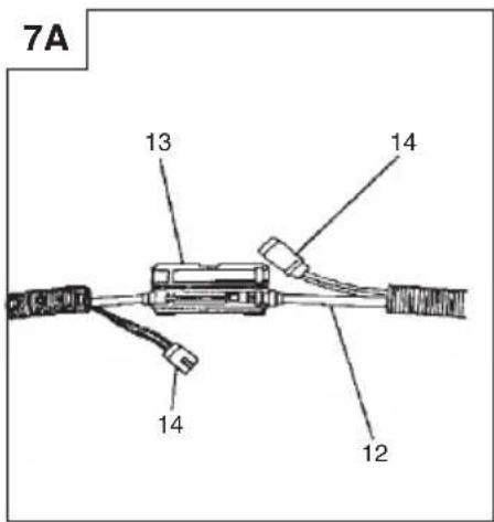
natural_image
Technical line drawing of a mechanical device with no visible text or symbols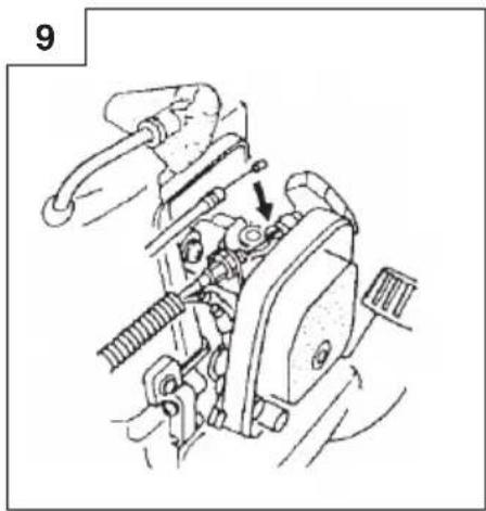
natural_image
Mechanical assembly diagram showing a valve mechanism with no visible text or symbols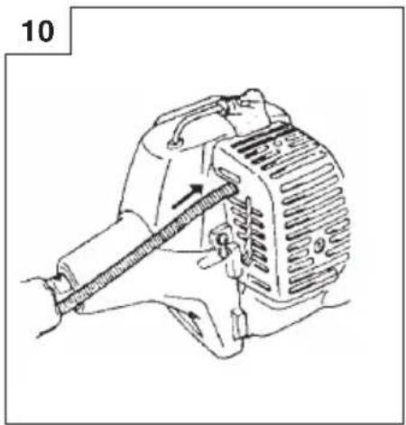
natural_image
Line drawing of a mechanical device with a lever and adjustment arrow (no text or symbols)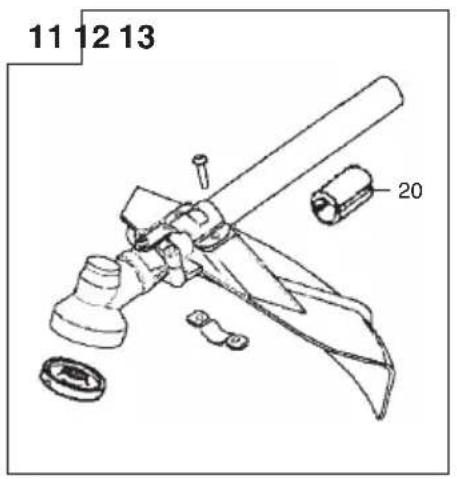
natural_image
Technical line drawing of a mechanical assembly with no visible text or symbols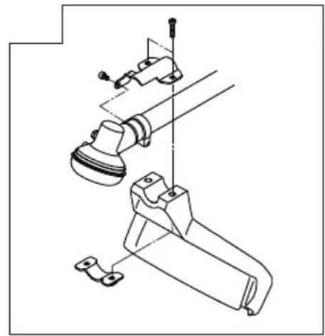
natural_image
Technical line drawing of a mechanical assembly with no visible text or symbols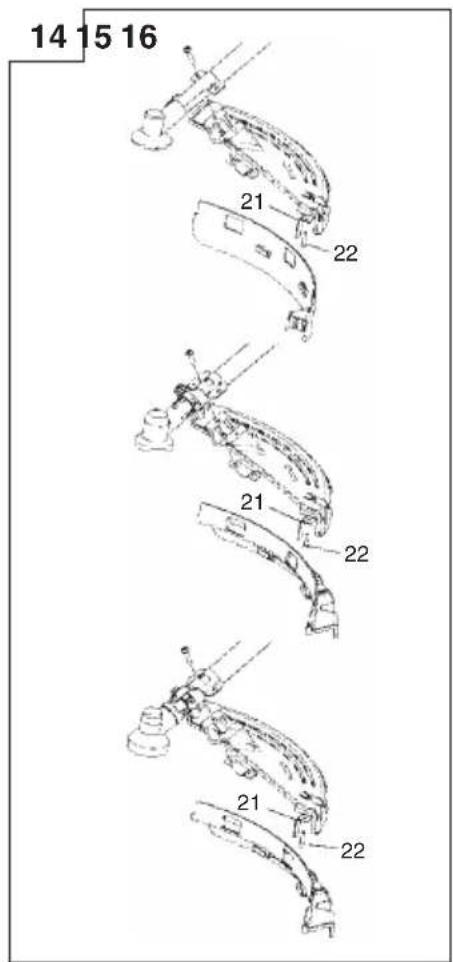
natural_image
Illustration of two hands holding a device with arrows indicating downward motion (no text or symbols)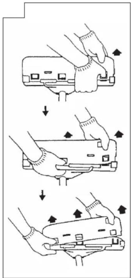


natural_image
Line drawing of a worker in safety gear holding equipment (no text or symbols)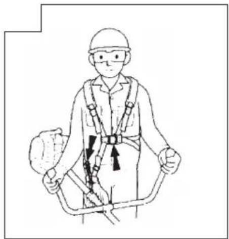
natural_image
Line drawing of a person wearing a full-body safety harness and helmet, holding equipment (no text or symbols)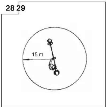
natural_image
Illustration of two hand tools: a manual tool and a handheld tool, both with arrows indicating movement or assembly (no text or symbols present)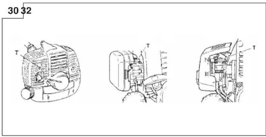
natural_image
Line drawing of a mechanical device with no visible text or symbols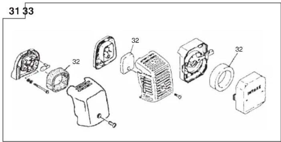
natural_image
Line drawing of a hand using a tool to adjust or install a mechanical component (no text or symbols visible)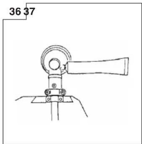
natural_image
Technical line drawing of a mechanical device with no visible text or symbols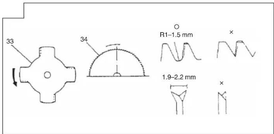
MEANINGS OF SYMBOLS
NOTE: Some units do not carry them.
| Symbols⚠ WARNINGThe engine exhaust from this product contains chemicals known to the State of California to cause cancer, birth defects and other reproductive harm. | |||
 | It is important that you read, fully understand and observe the following safety precautions and warnings. Careless or improper use of the unit may cause serious or fatal injury. |  | Shows maximum shaft speed. Do not use the cutting attachment whose max rpm is below the shaft rpm. |
 | Read, understand and follow all warnings and instructions in this manual and on the unit. |  | Gloves should be worn when necessary, e.g., when assembling cutting equipment. |
 | Always wear eye, head and ear protectors when using this unit. |  | Use anti-slip and sturdy footwear. |
 | Do not use metal/rigid blades when this sign is shown on the unit. |  | Blade thrust may occur when the spinning blade contacts a solid object in the critical area. A dangerous reaction may occur causing the entire unit and operator to be thrust violently. This reaction is called blade thrust. As a result, the operator may lose control of the unit which may cause serious or fatal injury. Blade thrust is more likely to occur in areas where it is difficult to see the material to be cut. |
 | Keep all children, bystanders and helpers 15 m away from the unit. If anyone approaches you, stop the engine and cutting attachment immediately. | ||
 | Be careful of thrown objects. | Do not attach handle above this point | Indicate handle location. Do not attach handle above this point. |
| Before using your machineRead the manual carefully.Check that the cutting equipment is correctly assembled and adjusted.Start the unit and check the carburetor adjustment. See “MAINTENANCE”. | |||
Contents
WHAT IS WHAT 7
WARNINGS AND SAFETY INSTRUCTIONS 8
SPECIFICATIONS 9
ASSEMBLY PROCEDURES 10
OPERATING PROCEDURES 11
MAINTENANCE....11
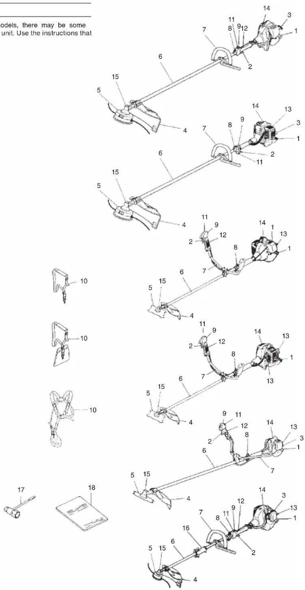
WHAT IS WHAT
Since this manual covers several models, there may be some difference between pictures and your unit. Use the instructions that apply to your unit.
- Fuel cap
- Throttle trigger
- Starter handle
- Blade guard
- Cutting attachment
- Drive shaft tube
- Handle bar
- Suspension eyelet
- Ignition switch
- Harness
- Throttle lock
- Throttle trigger lookout
- Choke lever
- Engine
- Angle transmission
- Joint case
- Combi box spanner
- Handling instructions
WARNINGS AND SAFETY INSTRUCTIONS
Operator safety
○ Always wear a safety face shield or goggles.
○ Always wear heavy, long pants, boots and gloves. Do not wear loose clothing, jewelry, short pants, sandals or go barefoot. Secure hair so it is above shoulder length.
○ Do not operate this tool when you are tired, ill or under the influence of alcohol, drugs or medication.
○ Never let a child or inexperienced person operate the machine.
○ Wear hearing protection. Pay attention to your surroundings. Be aware of any bystanders who may be signaling a problem. Remove safety equipment immediately upon shutting off engine.
Never start or run the engine inside a closed room or building. Breathing exhaust fumes can kill.
○ Keep handles free of oil and fuel.
○ Keep hands away from cutting equipment.
○ Do not grab or hold the unit by the cutting equipment.
When the unit is turned off, make sure the cutting attachment has stopped before the unit is set down.
When operation is prolonged, take a break from time to time so that you may avoid possible Hand-Arm Vibration Syndrome (HAVS) which is caused by vibration.
WARNING
○ Antivibration systems do not guarantee that you will not sustain Hand-Arm Vibration Syndrome or carpal tunnel syndrome. Therefore, continual and regular users should monitor closely the condition of their hands and fingers. If any symptoms of the above appear, seek medical advice immediately.
☐ If you are using any medical electric/electronic devices such as a pacemaker, consult your physician as well as the device manufacturer prior to operating any power equipment.
Unit/machine safety
○ Inspect the entire unit/machine before each use. Replace damaged parts. Check for fuel leaks and make sure all fasteners are in place and securely tightened.
○ Replace parts that are cracked, chipped or damaged in any way before using the unit/machine.
○ Make sure the safety guard is properly attached.
○ Keep others away when making carburetor adjustments.
○ Use only accessories as recommended for this unit/machine by the manufacturer.
WARNING
Never modify the unit/machine in any way. Do not use your unit/machine for any job except that for which it is intended.
Fuel safety
○ Mix and pour fuel outdoors and where there are no sparks or flames.
○ Use a container approved for fuel.
☐ Do not smoke or allow smoking near fuel or the unit/machine or while using the unit/machine.
○ Wipe up all fuel spills before starting engine.
○ Move at least 3 m away from fueling site before starting engine.
○ Stop engine before removing fuel cap.
Empty the fuel tank before storing the unit/machine. It is recommended that the fuel be emptied after each use. If fuel is left in the tank, store so fuel will not leak.
○ Store unit/machine and fuel in area where fuel vapors cannot reach sparks or open flames from water heaters, electric motors or switches, furnaces. etc.
WARNING
Fuel is easy to ignite or get explosion or inhale fumes, so that pay special attention when handling or filling fuel.
Cutting safety
○ Do not cut any material other than grass and brush.
○ Inspect the area to be cut before each use. Remove objects which can be thrown or become entangled.
☐ For respiratory protection, wear an aerosol protection mask when cutting the grass after insecticide is scattered.
Keep others including children, animals, bystanders and helpers outside the 15 m hazard zone. Stop the engine immediately if you are approached.
○ Always keep the engine on the right side of your body.
○ Hold the unit/machine firmly with both hands.
○ Keep firm footing and balance. Do not over-reach.
Keep all parts of your body away from the muffler and cutting attachment when the engine is running.
○ Keep cutting attachment below waist level.
When relocating to a new work area, be sure to shut off the machine and ensure that all cutting attachments are stopped.
○ Never place the machine on the ground when running.
○ Always ensure that the engine is shut off and any cutting attachments have completely stopped before clearing debris or removing grass from the cutting attachment.
○ Always carry a first-aid kit when operating any power equipment.
Never start or run the engine inside a closed room or building and/or near inflammable liquids. Breathing exhaust fumes can kill.
Maintenance safety
○ Maintain the unit/machine according to recommended procedures.
○ Disconnect the spark plug before performing maintenance except for carburetor adjustments.
○ Keep others away when making carburetor adjustments.
○ Use only genuine Hitachi replacement parts as recommended by the manufacturer.
Transport and storage
○ Carry the unit/machine by hand with the engine stopped and the muffler away from your body.
○ Allow the engine to cool, empty the fuel tank, and secure the unit/machine before storing or transporting in a vehicle.
Empty the fuel tank before storing the unit/machine. It is recommended that the fuel be emptied after each use. If fuel is left in the tank, store so fuel will not leak.
○ Store unit/machine out of the reach of children
○ Clean and maintain the unit carefully and store it in a dry place.
○ Make sure engine switch is off when transporting or storing.
○ When transporting in a vehicle, cover blade with blade cover.
If situations occur which are not covered in this manual, take care and use common sense. Contact your Hitachi dealer if you need assistance. Pay special attention to statements preceded by the following words:

WARNING
Indicates a strong possibility of severe personal injury or loss of life, if instructions are not followed.
CAUTION
Indicates a possibility of personal injury or equipment damage, if instructions are not followed.
NOTE
Helpful information for correct function and use.
CAUTION
Do not disassemble the recoil starter. You may get a possibility of personal injury with recoil spring.
SPECIFICATIONS
| Model | CG28EJ (L)CG28EJ (SL)CG28EJ | CG27EJ (SLP)CG27EJ (SP)CG27EJ (SLDP) | CG33EJ (L)CG33EJCG33EJ (S)CG33EJ (SL) | CG27EJ (SL)CG27EJ (S)CG27EJ (SLD) | |
 | Engine Size (ml) 28 26.9 | 33 27 | |||
 | Spark Plug | CHAMPION CJ6Y or RCJ6Y or equivalent | CHAMPION RCJ8 or equivalent | CHAMPION CJ6Y or RCJ6Y or equivalent | CHAMPION RCJ8Y or equivalent |
 | F u | e | I | T | a |
 | Dry Weight (kg) | 5.45.565.6 | 5.26.15.4 | 5.55.75.865.9 | 5.05.75.2 |
 | Sound pressure level LpA (dB (A))(EN27917) | 95.095.095.5 | 92.0 94.5 | 97.598.397.5 | |
 | Sound power level LwA (dB (A)) | 116 | |||
 | Vibration level (m/s2)(ISO7916)Front handleRear handleLeft handleRight handle |  2.6 4.13.5 5,62.4 2.51.9 2.0 2.6 4.13.5 5,62.4 2.51.9 2.0 | CG27EJ (SLP) CG27EJ (SLDP) CG27EJ (SLDP) 6.9 10.8 11.2 11.23.9 2.6 4.4 4.4CG27EJ(SP)5.5 3.96.4 3.6 6.9 10.8 11.2 11.23.9 2.6 4.4 4.4CG27EJ(SP)5.5 3.96.4 3.6 | CG33EJ (SL)  5.4 5.2 5.8 2.13.7 7.1 4.3 5.61.8 2.12.5 2.9 5.4 5.2 5.8 2.13.7 7.1 4.3 5.61.8 2.12.5 2.9 | CG27EJ (SLD)  5.8 2.1 5.73.2 4.5 3.14.6 2.33.4 2.0 5.8 2.1 5.73.2 4.5 3.14.6 2.33.4 2.0 |
NOTE
Equivalent noise level/vibration level are calculated as the time-weighted energy total for noise/vibration levels under various working conditions with the following time distribution: 1/2 Idle, 1/2 racing.
* All data subject to change without notice.
ASSEMBLY PROCEDURES
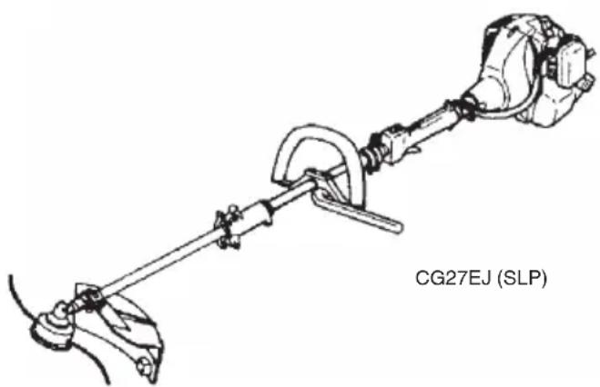
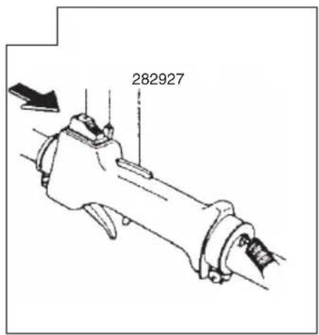
Drive shaft to engine (Fig. 1)
Loosen tube locking bolt (1) about ten turns so that the bolt point will not obstruct drive shaft tube to be inserted. When inserting drive shaft tube, hold the tube locking bolt outward preventing inside fitting from obstructing as well.
Insert the drive shaft into the clutch case of the engine properly until the marked position (2) on the drive shaft tube meets the clutch case.
NOTE
When it is hard to insert drive shaft up to the marked position on the drive shaft tube, turn drive shaft by the cutter mounting end clockwise or counter-clockwise. Tighten tube locking bolt lining up the hole in the shaft tube. Then tighten clamp bolt securely (3).
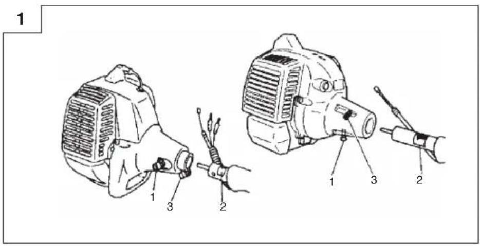
Installation of attachment
- Join the attachment in place of it.
- Make sure the lock pin (4) fits in the location hole (5) of tube and that the tube will not come off. (Fig. 2)
- Tighten the knob nut (6) securely. (Fig. 2)
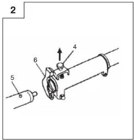
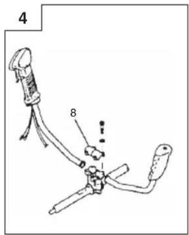
Installation of handle

WARNING
When you use steel/rigid blades on straight shaft trimmers or brush cutters, always use a barrier bar (7) and shoulder harness with the loop handle. (Fig. 3)
Attach the handle to the drive shaft tube with the angle towards the engine.
Adjust the location to the most comfortable position before operation.
NOTE
If your unit has handle location label on drive shaft tube, follow the illustration.
Remove the handle bracket (8) from the assembly. (Fig. 4)
Place the handles and attach the handle bracket with four bolts lightly. Adjust to appropriate position. Then attach it firmly with the bolts.
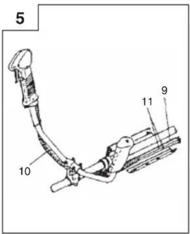
Put stop cords (11) and throttle wire (9) through protective tube (10), then unhook the hip pad. (Fig. 5)
Throttle wire / stop cord
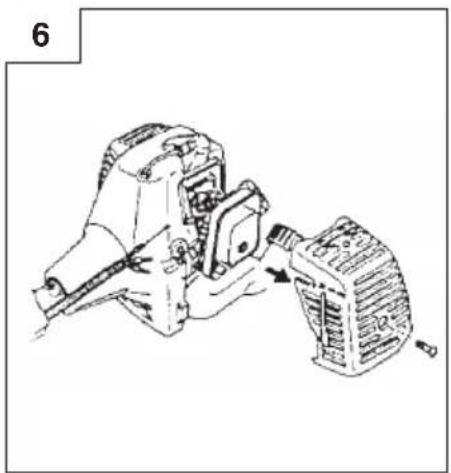
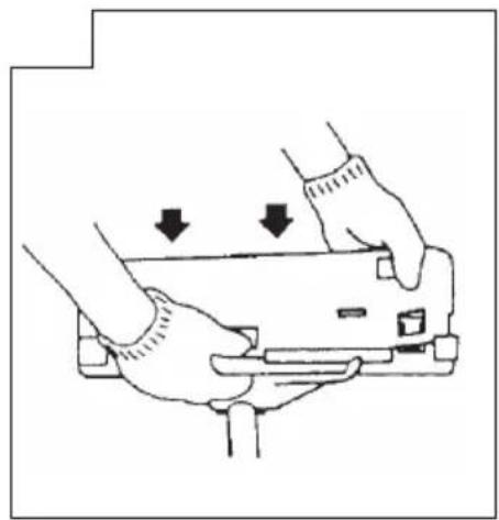
Remove air cleaner cover. (Fig. 6)
Connect stop cords. (Fig. 8)
Connect throttle wire end to carburetor. (Fig. 9)
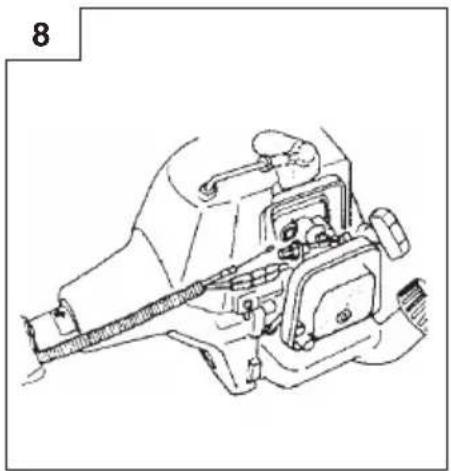
Convert throttle wire and stop cords together with protective tube provided up to air cleaner cover. (Fig. 10)
Throttle cable and stop cord (Fig. 7A)
(for CG33EJ (SL))
Connect throttle cables (12) by hooking each cut end of the cables and clamp the jointed part with connector case (13) which locks. Connect each end of stop cords (14).
NOTE
When removing connector case, insert coin or minus driver in slot in the middle and twist it.
Throttle wire / stop cord (Fig. 7)
(for CG27EJ (SLP)/(SP)/(SLDP))
Remove air cleaner cover. (Fig. 6)
Connect stop cords. (Fig. 8)
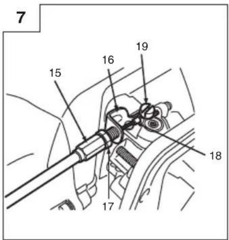
If the throttle outer end (15) is threaded on your unit, screw it into the cable adjuster stay (16) all the way, and then tighten this cable end using the adjuster nut (17) against the cable adjuster stay (16).
Connect throttle wire end (18) to carburetor (19) and install swivel cap (if so equipped) where is included in tool bag, onto swivel.
Cover throttle wire and stop cords together with protective tube provided up to air cleaner cover. (Fig. 10)
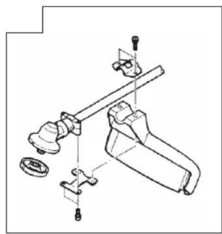
Installation of blade guard (Fig. 11, 12, 13, 14)
NOTE
The guard bracket may come already mounted to the gear case on some models.
Install the blade guard and the bracket spacers (20) (If so equipped) on drive shaft tube against angle transmission. Tighten the guard bracket firmly so that the blade guard does not swing or move down during operation.
Install the blade guard to the guard bracket, which also secures the guard to the gear case using the two guard mounting screws.
CAUTION
Some blade guards are equipped with sharp line limiters. Be careful with handling it.
NOTE (Fig. 14)
When using Hitachi aluminum head (CH-100 or CH-300) on your unit, the sharp line limiter (21) which is included in the tool bag, should be securely fastened to the blade guard using the bolt shown (22).
When using a trimmer head with two piece type blade guard, attach the guard extension to the blade guard. (Fig. 15)
NOTE
☐ When attaching the guard extension to the blade guard, the sharp line limiter must be removed from the blade guard, (if so installed).
○ If your unit has guard location label on drive shaft tube, follow the indication.
To remove the guard extension, refer to the drawings. Wear gloves as the extension has a sharp line limiter, then push the four square tabs on the guard one by one in order. (Fig. 16)
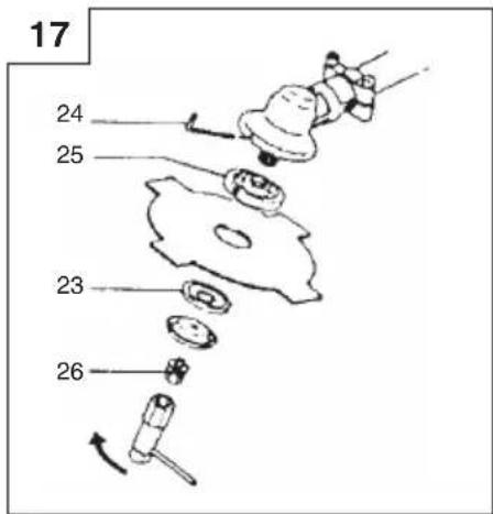
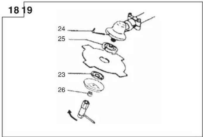
Installation of cutting blade (Fig. 17, 18)
(If so equipped)
When installing a cutting blade, make sure that there are no cracks or any damage in it and that the cutting edges are facing the correct direction.
NOTE
○ When installing cutter holder cap (23), be sure to set concave side upward.
Insert the alien wrench (24) into the hole of the angle transmission in order to lock the cutter holder (25). Please note that the cutter fixing bolt or nut (26) has left-handed threads, (clockwise to loosen/ counter-clockwise to tighten). Tighten the fixing bolt or nut with the box wrench.
CAUTION
Before operation, make sure the blade has been properly installed.
☐ If your unit is equipped with protection cover under a cutting blade, check it for wear or cracks before operation. If any damage or wear is found, replace it, as it is an article of consumption.
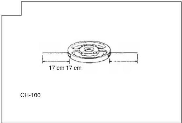
Installation of the Brain cutting head
NOTE
For installation see your Brain Owner's manual, provided with the Brain cutting head.

WARNING
For Hitachi Brain heads or Hitachi alloy head, use only flexible, non-metallic line recommended by the manufacturer. Never use wire or wire ropes. They can break off and become a dangerous projectile.
NOTE
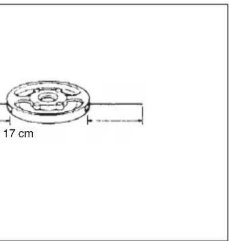
When using Hitachi alloy head (CH-100), initial cutting line length should be about 17 cm each. (Fig. 19)
OPERATING PROCEDURES
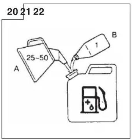
Fuel (Fig. 20)

WARNING
The trimmer is equipped with a two-stroke engine. Always run the engine on fuel, which is mixed with oil.
Provide good ventilation, when fueling or handling fuel.
Fuel
○ Always use branded 89 octane unleaded gasoline.
○ Use genuine two-cycle oil or use a mix between 25:1 to 50:1, please consult the oil bottle for the ratio or Hitachi dealer.
☐ If genuine oil is not available, use an anti-oxidant added quality oil expressly labeled for air-cooled 2-cycle engine use (JASO FC GRADE OIL or ISO EGC GRADE). Do not use BIA or TCW (2-stroke water-cooling type) mixed oil.
○ Never use multi-grade oil (10 W/30) or waste oil.
○ Always mix fuel and oil in a separate clean container.
Always start by filing half the amount of fuel, which is to be used. Then add the whole amount of oil. Mix (shake) the fuel mixture. Add the remaining amount of fuel.
Mix (shake) the fuel-mix thoroughly before filling the fuel tank.
Fueling

WARNING
○ Always shut off the engine before refueling.
○ Slowly open the fuel tank, when filling up with fuel, so that possible over-pressure disappears.
○ Tighten the fuel cap carefully, after fueling.
○ Always move the trimmer at least 3 m from the fueling area before starting.
Before fueling, clean the tank cap area carefully, to ensure dirt falls into the tank. Make sure that the fuel is well mixed by shaking the container, before fueling.
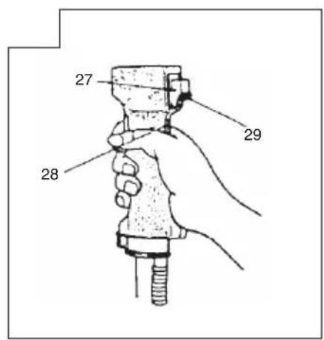
Starting (Fig. 21, 22)
CAUTION
Before starting, make sure the cutting attachment does not touch anything.
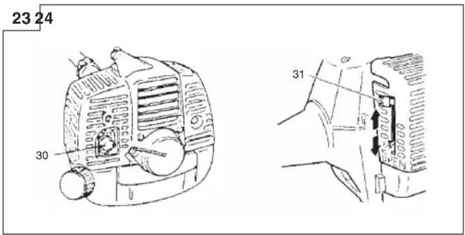
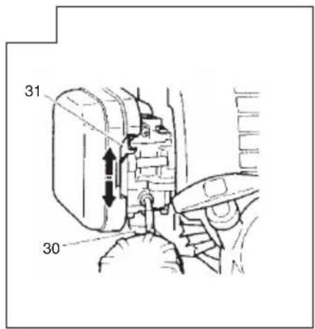
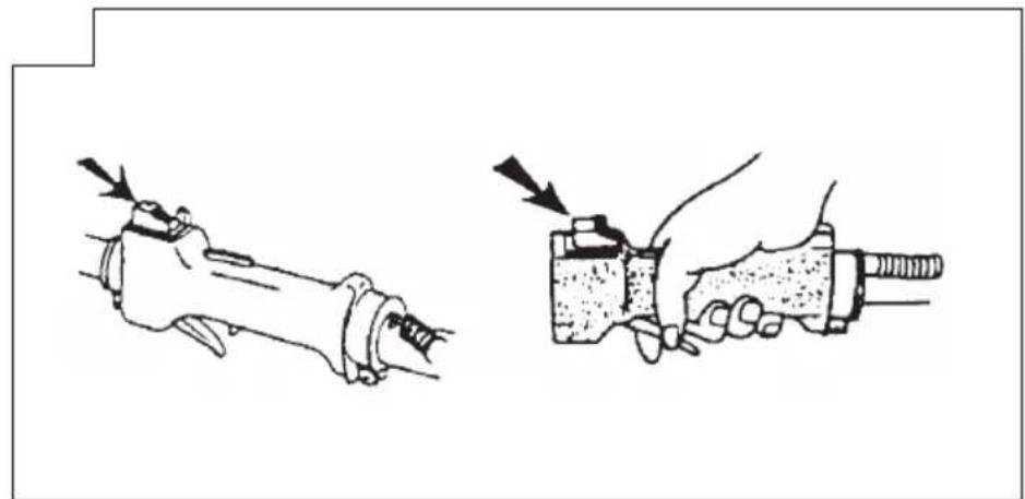
- Set ignition switch (27) to ON position. (Fig. 21, 22) * Push priming bulb (30) several times so that fuel flows through the bulb or return pipe. (If so equipped) (Fig. 23, 24)
- With the safety trigger (28) pressed (if so equipped), pull throttle trigger and push throttle lock (29), then slowly release the throttle trigger first, then the safety trigger. This will lock the throttle in starting position.
- Set choke lever to CLOSED position (31). (Fig. 23, 24)
- Pull recoil starter briskly, taking care to keep the handle in your grasp and not allowing it to snap back.
- When you hear the engine want to start, return choke lever to RUN position (open). Then pull recoil starter briskly again.
NOTE
If engine does not start, repeat procedures from 2 to 5.
- After starting engine, pull throttle trigger to release throttle lock. Then allow the engine about 2–3 minutes to warm up before subjecting it to any load.
Cutting (Fig. 25, 26, 27, 28)
When cutting, operate engine at over 6500 rpm. Extended time of use at low rpm may wear out the clutch prematurely.
○ Cut grass from right to left.
○ Blade thrust may occur when the spinning blade contacts a solid object in the critical area.
A dangerous reaction may occur causing the entire unit and operator to be thrust violently. This reaction is called blade thrust. As a result, the operator may lose control of the unit which may cause serious or fatal injury. Blade thrust is more likely to occur in areas where it is difficult to see the material to be cut.
☐ Wear the harness as shown in the figure (if so equipped). The blade turns counter-clockwise, therefore, be advised to operate the unit from right to left for efficient cutting. Keep onlookers out of working area at least 15 m.
NOTE
Press the quick release button or pull emergency release flap (If so equipped) in the event of emergency. (Fig. 27)

WARNING
If cutting attachment should strike against stones or other debris, stop the engine and make sure that the attachment and related parts are undamaged. When grass or vines wrap around attachment, stop engine and attachment and remove them.
Stopping (Fig. 29)
Decrease engine speed and run at an idle for a few minutes, then turn off ignition switch (27).

WARNING
A cutting attachment can injure while it continues to spin after the engine is stopped or power control is released. When the unit is turned off, make sure the cutting attachment has stopped before the unit is set down.
MAINTENANCE
MAINTENANCE, REPLACEMENT OR REPAIR OF THE EMISSION CONTROL DEVICES AND SYSTEMS MAY BE PERFORMED BY ANY NON-ROAD ENGINE REPAIR ESTABLISHMENT OR INDIVIDUAL.
Carburetor adjustment (Fig. 30)
at no
WARNING
○ The cutting attachment may be spinning during carburetor adjustments.
Never start the engine without the complete clutch cover and tube assembled! Otherwise the clutch can come loose and cause personal injuries.
In the carburetor, fuel is mixed with air. When the engine is test run at the factory, the carburetor is basically adjusted. A further adjustment may be required, according to climate and altitude. The carburetor has one adjustment possibility:
T = Idle speed adjustment screw.
Idle speed adjustment (T)
Check that the air filter is clean. When the idle speed is correct, the cutting attachment will not rotate. If adjustment is required, close (clockwise) the T-screw, with the engine running, until the cutting attachment starts to rotate. Open (counter-clockwise) the screw until the cutting attachment stops. You have reached the correct idle speed when the engine runs smoothly in all positions well below the rpm when the cutting attachment starts to rotate.
If the cutting attachment still rotates after idle speed adjustment, contact your Hitachi dealer.
NOTE
○ Standard Idle rpm is 2500–3000 rpm.
Some models sold areas with strict exhaust emission regulation do not have high and low speed carburetor adjustments. Such adjustments may allow the engine to be operated outside of their emission compliance limits. For these models, the only carburetor adjustment is idle speed.
For models that equipped with low and high speed adjustments; carburetors are preset at the factory. Minor adjustments may optimize performance based on climate, altitude, etc. Never turn the adjustment screws in increments greater than 90 degrees, as engine damage can result from incorrect adjustment, if you are not familiar with type of adjustment-assistance Hitachi dealer.

WARNING
When the engine is idling the cutting attachment must under no circumstances rotate.
Air filter (Fig. 31)
The air filter must be cleaned from dust and dirt in order to avoid:
○ Carburetor malfunctions
○ Starting problems
○ Engine power reduction
○ Unnecessary wear on the engine parts
○ Abnormal fuel consumption
Clean the air filter daily or more often if working in exceptionally dusty areas.
Cleaning the air filter
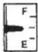
Remove the air filter cover and the filter (32). Rinse it in warm soap suds. Check that the filter is dry before reassembly. An air filter that has been used for some time cannot be cleaned completely. Therefore, it must regularly be replaced with a new one. A damaged filter must always be replaced.
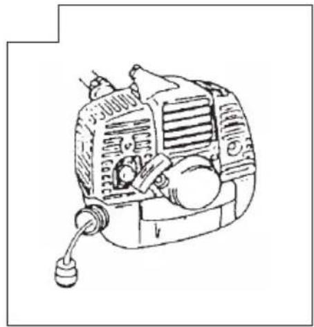
Fuel filter (Fig. 32)
Drain all fuel from fuel tank and pull fuel filter line from tank. Pull filter element out of holder assembly and rinse element in warm water with detergent.
Rinse thoroughly until all traces of detergent are eliminated. Squeeze, do not wring, away excess water and allow element to air dry.
NOTE
If element is hard due to excessive dirt buildup, replace it.
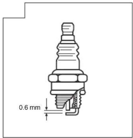
Spark plug (Fig. 33)
The spark plug condition is influenced by:
○ An incorrect carburetor setting
○ Wrong fuel mixture (too much oil in the gasoline)
○ A dirty air fi Iter
○ Hard running conditions (such as cold weather)
These factors cause deposits on the spark plug electrodes, which may result in malfunction and starting difficulties. If the engine is low on power, difficult to start or runs poorly at idling speed, always check the spark plug first. If the spark plug is dirty, clean it and check the electrode gap. Re-adjust if necessary. The correct gap is 0.6 mm. The spark plug should be replaced after about 100 operation hours or earlier if the electrodes are badly eroded.
NOTE
In some areas, local law requires using a resistor spark plug to suppress ignition signals. If this machine was originally equipped with resistor spark plug, use same type of spark plug for replacement.
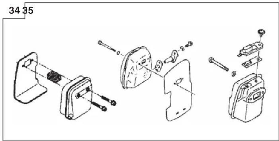
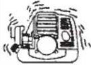
Muffler (Fig. 34)
Remove the muffler and clean out any excess carbon from the exhaust port or muffler inlet every 100 hours of operation.
Cylinder (Engine cooling) (Fig. 35)
The engine is air cooled, and air must circulate freely around engine and over cooling fins on cylinder head to prevent overheating.
Every 100 operating hours, or once a year (more often if conditions require), clean fins and external surfaces of engine of dust, dirt and oil deposits which can contribute to improper cooling.
NOTE
Do not operate engine with engine shroud or muffler guard removed as this will cause overheating and engine damage.
Angle transmission (Fig. 36)
Check angle transmission or angle gear for grease level about every 50 hours of operation by removing the grease filler plug on the side of angle transmission.
If no grease can be seen on the flanks of the gears, fill the transmission with quality lithium based multipurpose grease up to 3/4. Do not completely fill the transmission.
Blade (Fig. 37)

WARNING
Wear protective gloves when handling or performing maintenance on the blade.
○ Use a sharp blade. A dull blade is more likely to snag and thrust. Replace the fastening nut if it is damaged and hard to tighten.
○ When replacing blade, purchase one recommended by Hitachi, with a 25.4 mm (one inch) ft tting hole.
When installing a saw blade (34), always face the stamped side up. In the case of a 4 tooth blade (33), it can be used on either side.
○ Use the correct blade for the type of work.
○ When replacing blades, use appropriate tools.
When cutting edges become dull, re-sharpen or file as shown in the illustration. Incorrect sharpening may cause excessive vibration.
○ Discard blades that are bent, warped, cracked, broken or damaged in any way.
NOTE
When sharpening blade it is important to maintain an origi shape of radius at the base of the tooth to avoid cracking.
Maintenance schedule
Below you will find some general maintenance instructions. For further information please contact your Hitachi dealer.
Daily maintenance
○ Clean the exterior of the unit.
○ Check that the harness is undamaged.
○ Check the blade guard for damage or cracks. Change the guard in case of impacts or cracks.
☐ Check that the cutting attachment is properly centred, sharp, and without cracks. An off-centre cutting attachment induces heavy vibrations that may damage the unit.
○ Check that the cutting attachment nut is sufficiently tightened.
○ Make sure that the blade transport guard is undamaged and that it can be securely fitted.
○ Check that nuts and screws are sufficiently tightened.
Weekly maintenance
○ Check the starter, especially the cord and return spring.
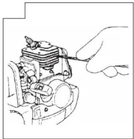
○ Clean the exterior of the spark plug.
○ Remove it and check the electrode gap. Adjust it to 0.6 mm, or change the spark plug.
○ Clean the cooling fins on the cylinder and check that the air intake at the starter is not clogged.
○ Check that the angle gear is filled with grease up to 3/4.
○ Clean the air fi Iter.
Monthly maintenance
○ Rinse the fuel tank with gasoline.
○ Clean the exterior of the carburetor and the space around it.
○ Clean the fan and the space around it.
SYMBOLBEDEUTUNGEN
WAARSCHUWINGEN EN VEILIGHEIDSINSTRUCTIES ....39
SPECIFICATIES....40
MONTAGEPROCEDURES....41
BEDIENING 42
ONDERHOUD 42
WAT IS WAT
WAARSCHUWINGEN EN VEILIGHEIDSINSTRUCTIES
Corte (Fig. 25, 26, 27, 28)
Cortar (Fig. 25, 26, 27, 28)
Klipning (Fig. 25, 26, 27, 28)
(for CG27EJ (SLP)/(SP)/(SLDP))
Klipping (Fig. 25, 26, 27, 28)
○ Feil drivstofblanding (for mye olje i drivstoff et)
○ Et skittent luftfi Iter
(malleissa CG27EJ (SLP)/(SP)/(SLDP))
natural_image
Line drawing of a quill pen in an inkwell (no text or symbols)
natural_image
Line drawing of a quill pen in an inkwell (no text or symbols)
natural_image
Line drawing of a quill pen with inkwell (no text or symbols)| English EC DECLARATION OF CONFORMITY Português DECLARAÇÃO DE CONFORMIDADE CE | |
| (Applies to Europe only)We declare under our sole responsibility that this product is in conformity with Council Directive 98/37/EC, 2004/108/EC and 2000/14/EC. This product also complies with the essential requirements of 2006/42/EC to be applied from 29 December 2009 instead of 98/37/EC.The following standards have been taken into consideration.ISO 7112/7113/7916/7917/7918/8380/11682 (EN ISO 12100-2, EN ISO 11806)This declaration is applicable to the product affi xed CE marking. | |
| Deutsch ERKLÄRUNG ZUR KONFORMITÄT MIT CE-REGELN Svenska EF-DEKLARATION BETRÄFFANDE LIKFORMIGHET | |
| (Gilt nur für Europa)Wir erklären eigenverantwortlich, dass dieses Produkt den Bestimmungen der Richtlinien 98/37/EG, 2004/108/EG und 2000/14/EG des Europäischen Rates entspricht. Dieses Produkt entspricht auch den wesentlichen Anforderungen der Richtlinie 2006/42/CE, die ab 29. Dezember 2009 statt 98/37/CE in Kraft ist.Die nachfolgenden Standards wurden in Betracht gezogen.ISO 7112/7113/7916/7917/7918/8380/11682 (EN ISO 12100-2, EN ISO 11806)Diese Erklärung gilt für Produkte, die die CE-Markierung tragen. | |
| Français DECLARATION DE CONFORMITE CE Dansk EF-OVERENSS TEMMELŞESERKLÄERING | |
| (Concerne l'Europe uniquement)Nous déclarons sur la foi de notre seule responsabilité que ce produit est conforme aux dispositions des Directives du Conseil de l'Union européenne 98/37/EC, 2004/108/EC et 2000/14/EC. Ce produit est également conforme aux exigences essentielles de 2006/42/CE applicables à compter du 29 Décembre 2009 en lieu et place de celle de 98/37/CE.Les normes suivantes ont été prises en considération.ISO 7112/7113/7916/7917/7918/8380/11682 (EN ISO 12100-2, EN ISO 11806)Cette déclaration s'applique aux produits désignés CE. | |
| Italiano DICHIARAZIONE DI CONFORMITÀ CE Norsk EF'S ERKLÄRING OM OVERENSSTEMMELSE | |
| (Si applica solo all'Europa)Dichiariamo sotto la nostra esclusiva responsabilità che questo prodotto è conforme alle Direttive del Consiglio 98/37/CE, 2004/108/CE e 2000/14/CE.Questo prodotto è conforme anche ai requisiti 2006/42/CE vigenti a partire dal 29 dicembre 2009 invece dei requisiti 98/37/CE.Sono stati presi in considerazione i seguenti standard.ISO 7112/7113/7916/7917/7918/8380/11682 (EN ISO 12100-2, EN ISO 11806)Questa dichiarazione è applicabile ai prodotti cui sono applicati i marchi CE. | |
| Nederlands EC VERKLARING VAN CONFORMITEIT Suomi EY-ILMO TUS YHDENMUKAISUUDESTA | |
| (Geldt alleen voor Europa)Wij verklaren onder eigen verantwoordelijkheid dat dit product voldoet aan de richtlijn 98/37/EC, 2004/108/EC en 2000/14/EC. Dit product voldoet ook aan de essentiële vereisten van 2006/42/EC toegepast vanaf december 2009, in plaats van 98/37/EC.De volgende standaards zijn toegepast.ISO 7112/7113/7916/7917/7918/8380/11682 (EN ISO 12100-2, EN ISO 11806)Deze verklaring is van toepassing op produkten voorzien van de CE-markeringen. | |
| Español DECLARACIÓN DE CONFORMIDAD DE LA CE | |
| (De aplicación sólo en Europa)Declaramos bajo nuestra exclusiva responsabilidad que este producto es conforme con las Directivas 98/37/CE, 2004/108/CE y 2000/14/CE. Este producto también cumple con los requisitos esenciales de 2006/42/CE aplicables desde el 29 de diciembre de 2009 en lugar de 98/37/CE.Se han tenido en consideración las siguientes normas.ISO 7112/7113/7916/7917/7918/8380/11682 (EN ISO 12100-2, EN ISO 11806)Esta declaración se aplica a los productos con marcas de la CE. | |
| Representative offi ce in EuropeHitachi Power Tools Europe GmbHSiemensring 34, 47877 Willich 1, F. R. GermanyTechnical file at:Hitachi Koki Europe Ltd.Clonshaugh Business & Technology Park, Dublin 17, IrelandHead offi ce in JapanHitachi Koki Co., Ltd.Shinagawa Intercity Tower A, 15-1, Konan 2-chome,Minato-ku, Tokyo, Japan |
- MEANINGS OF SYMBOLS
- Contents
- WHAT IS WHAT
- WARNINGS AND SAFETY INSTRUCTIONS
- Operator safety
- WARNING
- Unit/machine safety
- Fuel safety
- Cutting safety
- Maintenance safety
- Transport and storage
- CAUTION
- NOTE
- ASSEMBLY PROCEDURES
- Drive shaft to engine (Fig. 1)
- Installation of attachment
- Installation of handle
- Throttle wire / stop cord
- Throttle cable and stop cord (Fig. 7A)
- (for CG33EJ (SL))
- Throttle wire / stop cord (Fig. 7)
- (for CG27EJ (SLP)/(SP)/(SLDP))
- Installation of blade guard (Fig. 11, 12, 13, 14)
- NOTE (Fig. 14)
- Installation of cutting blade (Fig. 17, 18)
- Installation of the Brain cutting head
- OPERATING PROCEDURES
- Fuel (Fig. 20)
- Fuel
- Fueling
- Starting (Fig. 21, 22)
- Cutting (Fig. 25, 26, 27, 28)
- Stopping (Fig. 29)
- MAINTENANCE
- Carburetor adjustment (Fig. 30)
- Idle speed adjustment (T)
- Air filter (Fig. 31)
- Cleaning the air filter
- Fuel filter (Fig. 32)
- Spark plug (Fig. 33)
- Muffler (Fig. 34)
- Cylinder (Engine cooling) (Fig. 35)
- Angle transmission (Fig. 36)
- Blade (Fig. 37)
- Maintenance schedule
- Daily maintenance
- Weekly maintenance
- Monthly maintenance
- SYMBOLBEDEUTUNGEN
- WAT IS WAT
- WAARSCHUWINGEN EN VEILIGHEIDSINSTRUCTIES
- Corte (Fig. 25, 26, 27, 28)
- Cortar (Fig. 25, 26, 27, 28)
- Klipning (Fig. 25, 26, 27, 28)
- Klipping (Fig. 25, 26, 27, 28)
- (malleissa CG27EJ (SLP)/(SP)/(SLDP))
Brand : HITACHI
Model : CG 27EJ
Category : Lawn mower