
H 70SD - Hammer HITACHI - Free user manual and instructions
Find the device manual for free H 70SD HITACHI in PDF.

| Product Type | Demolition Hammer |
| Brand | Hitachi |
| Model | H 70SD |
| Voltage (according to region) | 110 V, 230 V, 240 V |
| Rated Power Input | 1240 W |
| Full Load Impact Rate | 1400 min⁻¹ |
| Weight (without cord and side handle) | 20 kg |
| Accessory Type | Bull point, cold chisel, clay spade, etc. |
| Applications | Concrete breaking, chiseling, grooving, bar cutting |
| Lubrication | Grease, replace every 6 months |
| Retaining System | Locking mechanism for accessories |
| Protection | Sealed construction against dust and leaks |
| Carbon Brushes | With auto-stop, replaceable |
| Vibration (chiseling) | ah,Cheq = 19.8 m/s², uncertainty K = 3.8 m/s² |
| Recommended Safety Equipment | Eye protection, hearing protection, safety shoes |
| Routine Maintenance | Cleaning, screw inspection, grease replacement |
| Spare Parts | Carbon brushes, accessories, grease |
| Repairability | Refer to a Hitachi authorized service center |
| Warranty | Conforms to statutory/national regulations |
Frequently Asked Questions - H 70SD HITACHI
User questions about H 70SD HITACHI
0 question about this device. Answer the ones you know or ask your own.
Ask a new question about this device
Download the instructions for your Hammer in PDF format for free! Find your manual H 70SD - HITACHI and take your electronic device back in hand. On this page are published all the documents necessary for the use of your device. H 70SD by HITACHI.
USER MANUAL H 70SD HITACHI
natural_image
Line drawing of a soldering iron with a pointed tip and handle (no text or symbols)Read through carefully and understand these instructions before use. Diese Anleitung vor Benutzung des Werkzeugs sorgfältig durchlesen und verstehen. Lire soigneusement et bien assimiler ces instructions avant usage. Prima dell'uso leggere attentamente e comprendere queste istruzioni. Deze gebruiksaanwijzing s.v.p. voor gebruik zorgvuldig doorlezen. Leer cuidadosamente y comprender estas instrucciones antes del uso. Antes de usar, leia com cuidado para assimilar estas instruções. Διαβάστε προσεκτικά και κατανοήσετε αυτές τις οδηγίες πριν τη χρήση.

Handling instructions Bedienungsanleitung Mode d'emploi Istruzioni per l'uso Gebruiksaanwijzing Instrucciones de manejo Instruções de uso Οδηγίες χειρισμού
Hitachi Koki
1
2
natural_image
Technical line drawing of a soldering iron with an arrow indicating direction (no text or symbols)3
4
natural_image
Mechanical diagram showing a lever mechanism with directional arrows indicating motion (no text or symbols)5
natural_image
Technical line drawing of a mechanical tool with a pointed tip and handle, mounted on a base (no text or symbols present)6
| English Deutsch Français Italiano | ||||
| 1 | Tool shank Werkzeugschaft Queue d’outil | Gambo dell’utensile | ||
| 2 | Retainer Rückhalter Tige de retenue | Sostegno | ||
| 3 | Front cover Frontdeckel Couvercle frontal | Coperchio anteriore | ||
| 4 | Recessed portion Ausgesparter Teil Section rentrée | Parte repressa | ||
| 5 | Wear limit Verschleißgrenze Limite d’usure | Limite d’usura | ||
| 6 | No. of Carbon brush Nr. der kohlebürste No. de balai en carbone | Numero delle spazzole di carbone | ||
| 7 | Cap cover Kappendeckel Couvercle | Copri-tappo | ||
| 8 | Hexagon socket hd. bolt M4 × 12 | Sechskantsteckfassung Bou für Bolzen M4 × 12 | lon hexagonal M4 × 12 | Bullone a teste easgonale M4 × 12 |
| Nederlands | Español | Português | Ελληνικά | |
| 1 | Boorschacht | Barrena | Haste da ferramenta | Στέλεχος εργαλείου |
| 2 | Houder | Retén | Retentor | Αντιστήριγμα |
| 3 | Voorzijde | Cubierta delantera | Tampa frontal | Μπροστινό κάλυμμα |
| 4 | Het verlaagde gedeelte | Parte hendida | Parte rebaixada | Τμήμα που έχει εισχωρήσει |
| 5 | Slijtage-limiet | Límite de desgaste | Limite de desgaste | Όριο φθοράς |
| 6 | Nr. van koolborstel | No. de contacto de carbón | No de escova de carvão | Αρ. Καρβουνακίων |
| 7 | Kap-afdekking | Cubierta de la tapa | Protetor da tampa | Καπάκι καλύμματος |
| 8 | Bout met zeskantige kop M4 × 12Symbols⚠ WARNINGThe following show symbols used for the machine. Be sure that you understand their meaning before use. | Perno de cabeza hexagonal M4 × 12Symbole⚠ WARNUNGDie folgenden Symbole werden für diese Maschine verwendet. Achten Sie darauf, diese vor der Verwendung zu verstehen. | Parafuso de cabeça sextavada M4 × 12Symboles⚠ AVERTISSEMENTLes symboles suivants sont utilisés pour l’outil. Bien se familiariser avec leur signification avant d’utiliser l’outil. | Μπουλόνι εξαγ. κοίλης κεφαλήςSimboli⚠ AVVERTENZADi seguito mostriamo i simboli usati per la macchina. Assicurarsi di comprenderne il significato prima dell’uso. |
 | Read all safety warnings and all instructions.Failure to follow the warnings and instructions may result in electric shock, fire and/or serious injury. | Lesen Sie sämtliche Sicherheitshinweise und Anweisungen durch.Wenn die Warnungen und Anweisungen nicht befolgt werden, kann es zu Stromschlag, Brand und/oder ernsthaftenVerletzungen kommen. | Lire tous les avertissements de sécurité et toutes les instructions.Tout manquement à observer ces avertissements et instructions peut engendrer des chocs électriques, des incendies et/ou des blessures graves. | Leggere tutti gli avvertimenti di sicurezza e tutte le istruzioni.La mancata osservanza degli avvertimenti e delle istruzioni potrebbe essere causa di scosse elettriche, incendi e/o gravi lesioni. |
 | Only for EU countriesDo not dispose of electric tools together with household waste material!In observance of European Directive 2002/96/EC on waste electrical and electronic equipment and its implementation in accordance with national law, electric tools that have reached the end of their life must be collected separately and returned to an environmentally compatible recycling facility. | Nur für EU-LänderWerfen Sie Elektrowerkzeuge nicht in den Hausmüll!Gemäss Europäischer Richtlinie 2002/96/EG über Elektro- und Elektronik-Altgeräte und Umsetzung in nationales Recht müssen verbrauchte Elektrowerkzeuge getrennt gesammelt und einer umweltgerechten Wiederververitung zugeführt werden. | Pour les pays européens uniquementNe pas jeter les appareils électriques dans les ordures ménagères!Conformément à la directive européenne 2002/96/EG relative aux déchets d’équipements électriques ou électroniques (DEEE), et à sa transposition dans la législation nationale, les appareils électriques doivent être collectés à part et être soumis à un recyclage respectueux de l’environnement. | Solo per Paesi UENon gettare le apparecchiature elettriche tra i rifiuti domestici.Secondo la Direttiva Europea 2002/96/CE sui rifiuti di apparecchiature elettriche ed elettroniche e la sua attuazione in conformità alle norme nazionali, le apparecchiature elettriche esauste devono essere raccolte separatamente, al fine di essere reimpiegate in modo eco-compatibile. |
 | Symbolen⚠ WAARSCHUWINGHieronder staan symbolen afgebeeld die van toepassing zijn op deze machine. U moet de betekenis hiervan begrijpen voor gebruik. | Símbolos⚠ ADVERTENCIAA continuación se muestran los símbolos usados para la máquina. Asegúrese de comprender su significado antes del uso. | Símbolos⚠ AVISOA seguir aparecem os símbolos utilizados pela máquina. Assimile bem seus significados antes do uso. | Σύμβολα⚠ ΠΡΟΣΟΧΗΤα παρακάτω δείχνουν τα σύμβολα που χρησιμοποιούνται στο μηχάνημα. Βεβαιωθείτε ότι κατανοείτε τη σημασίας τους πριν τη χρήση. |
 | Lees alle waarschuwingen en instructies aandachtig door.Nalating om de waarschuwingen en instructies op te volgen kan in een elektrische schok, brand en/of ernstig letsel resulteren. | Lea todas las instrucciones y advertencias de seguridad.Si no se siguen las advertencias e instrucciones, podría producirse una descarga eléctrica, un incendio y/o daños graves. | Leia todas as instruções e avisos de segurança.Se não seguir todas as instruções e os avisos, pode provocar um choque eléctrico, incêndio e/ou ferimentos graves. | Διαθάζετε όλες τις προειδοποιήσεις ασφαλείας και όλες τις οδηγίες.Η μη τήρηση των προειδοποιήσεων και οδηγιών μπορεί να προκαλέσει ηλεκτροπληξία, πυρκαγιά κανή σοβαρό τραιματισμό. |
 | Alleen voor EU-landen Geef elektrisch gereedschap niet met het huisvuil mee!Volgens de Europese richtlijn 2002/96/EG inzake oude elektrische en elektronische apparaten en de toepassing daarvan binnen de nationale wetgeving, dient gebruikt elektrisch gereedschap gescheiden te worden ingezameld en te worden afgevoerd naar een recycle bedrijf dat voldoet aan de geldende milieu-eisen. | Sólo para países de la Unión Europea¡No deseche los aparatos eléctricos junto con los residuos domésticos!De conformidad con la Directiva Europea 2002/96/CE sobre residuos de aparatos eléctricos y electrónicos y su aplicación de acuerdo con la legislación nacional, las herramientas eléctricas cuya vida útil haya llegado a su fin se deberán recoger por separado y trasladar a una planta de reciclaje que cumpla con las exigencias ecológicas. | Apenas para países da UE Não deite ferramentas eléctricas no lixo doméstico!De acordo com a directiva europeia 2002/96/CE sobre ferramentas eléctricas e electrónicas usadas e a transposição para as leis nacionais, as ferramentas eléctricas usadas devem ser recolhidas em separado e encaminhadas a uma instalação de reciclagem dos materiais ecológica. | Μόνο για τις χώρες της ΕΕΜην πετάτε τα ηλεκτρικά εργαλεία στον κάδο οικιακών απορριμμάτων!Σύμφωνα με την ευρωπαϊκή οδηγία 2002/96/ΕΚ περί ηλεκτρικών και ηλεκτρονικών συσκειών και την ενσωμάτωσή της στο εθνικό δίκαιο, τα ηλεκτρικά εργαλεία πρέπει να συλλέγονται ξεχωριστά και να επιστρέφονται για ανακύκλωση με τρόπο φιλικό προς το περιβάλλον. |
GENERAL POWER TOOL SAFETY WARNINGS

WARNING
Read all safety warnings and all instructions.
Failure to follow the warnings and instructions may result in electric shock, fire and/or serious injury.
Save all warnings and instructions for future reference.
The term "power tool" in the warnings refers to your mains-operated (corded) power tool or battery-operated (cordless) power tool.
1) Work area safety
a) Keep work area clean and well lit.
Cluttered or dark areas invite accidents.
b) Do not operate power tools in explosive atmospheres, such as in the presence of flammable liquids, gases or dust.
Power tools create sparks which may ignite the dust or fumes.
c) Keep children and bystanders away while operating a power tool.
Distractions can cause you to lose control.
2) Electrical safety
a) Power tool plugs must match the outlet.
Never modify the plug in any way.
Do not use any adapter plugs with earthed (grounded) power tools.
Unmodified plugs and matching outlets will reduce risk of electric shock.
b) Avoid body contact with earthed or grounded surfaces, such as pipes, radiators, ranges and refrigerators.
There is an increased risk of electric shock if your body is earthed or grounded.
c) Do not expose power tools to rain or wet conditions.
Water entering a power tool will increase the risk of electric shock.
d) Do not abuse the cord. Never use the cord for carrying, pulling or unplugging the power tool.
Keep cord away from heat, oil, sharp edges or moving parts.
Damaged or entangled cords increase the risk of electric shock.
e) When operating a power tool outdoors, use an extension cord suitable for outdoor use.
Use of a cord suitable for outdoor use reduces the risk of electric shock.
f) If operating a power tool in a damp location is unavoidable, use a residual current device (RCD) protected supply.
Use of an RCD reduces the risk of electric shock.
3) Personal safety
a) Stay alert, watch what you are doing and use common sense when operating a power tool.
Do not use a power tool while you are tired or under the influence of drugs, alcohol or medication.
A moment of inattention while operating power tools may result in serious personal injury.
b) Use personal protective equipment. Always wear eye protection.
Protective equipment such as dust mask, non-skid safety shoes, hard hat, or hearing protection used for appropriate conditions will reduce personal injuries.
c) Prevent unintentional starting. Ensure the switch is in the off-position before connecting to power source and/or battery pack, picking up or carrying the tool.
Carrying power tools with your finger on the switch or energising power tools that have the switch on invites accidents.
d) Remove any adjusting key or wrench before turning the power tool on.
A wrench or a key left attached to a rotating part of the power tool may result in personal injury.
e) Do not overreach. Keep proper footing and balance at all times.
This enables better control of the power tool in unexpected situations.
f) Dress properly. Do not wear loose clothing or jewellery. Keep your hair, clothing and gloves away from moving parts.
Loose clothes, jewellery or long hair can be caught in moving parts.
g) If devices are provided for the connection of dust extraction and collection facilities, ensure these are connected and properly used.
Use of dust collection can reduce dust related hazards.
4) Power tool use and care
a) Do not force the power tool. Use the correct power tool for your application.
The correct power tool will do the job better and safer at the rate for which it was designed.
b) Do not use the power tool if the switch does not turn it on and off.
Any power tool that cannot be controlled with the switch is dangerous and must be repaired.
c) Disconnect the plug from the power source and/or the battery pack from the power tool before making any adjustments, changing accessories, or storing power tools.
Such preventive safety measures reduce the risk of starting the power tool accidentally.
d) Store idle power tools out of the reach of children and do not allow persons unfamiliar with the power tool or these instructions to operate the power tool.
Power tools are dangerous in the hands of untrained users.
e) Maintain power tools. Check for misalignment or binding of moving parts, breakage of parts and any other condition that may affect the power tool's operation.
If damaged, have the power tool repaired before use.
Many accidents are caused by poorly maintained power tools.
f) Keep cutting tools sharp and clean.
Properly maintained cutting tools with sharp cutting edges are less likely to bind and are easier to control.
g) Use the power tool, accessories and tool bits etc. in accordance with these instructions, taking into account the working conditions and the work to be performed.
Use of the power tool for operations different from those intended could result in a hazardous situation.
5) Service
a) Have your power tool serviced by a qualified repair person using only identical replacement parts.
This will ensure that the safety of the power tool is maintained.
PRECAUTION
Keep children and infirm persons away.
When not in use, tools should be stored out of reach of children and infirm persons.
DEMOLITION HAMMER SAFETY WARNINGS
1. Wear ear protectors.
Exposure to noise can cause hearing loss.
2. Use auxiliary handle(s), if supplied with the tool.
Loss of control can cause personal injury.
-
Hold power tool by insulated gripping surfaces, when performing an operation where the cutting accessory may contact hidden wiring or its own cord. Cutting accessory contacting a "live" wire may make exposed metal parts of the power tool "live" and could give the operator an electric shock.
-
Do not touch the bit during or immediately after operation. The bit becomes very hot during operation and could cause serious burns.
-
Before starting to break, chip or drill into a wall, floor or ceiling, thoroughly confirm that such items as electric cables or conduits are not buried inside.
-
Properly set the bit holder
-
At the start of work, confirm screw tightening.
-
When working at a highly elevated location, pay attention to articles and persons below.
-
Wear protective shoes to protect your feet.
SPECIFICATIONS
| Voltage (by areas)* (110 V, 230 V, 240 V) | |
| Power Input 1240 W* | |
| Full-load Impact Rate 1400 min | ^-1 (/min) |
| Weight (without cord, side handle) 20 kg |
* Be sure to check the nameplate on this Demolition Hammer as it is subject to change by areas.
STANDARD ACCESSORIES
(1) Case ...... 1
Standard accessories are subject to change without notice.
OPTIONAL ACCESSORIES (sold separately)
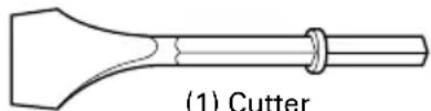
○Asphalt Cutting
natural_image
Simple line drawing of a cutter tool (no text or symbols on the diagram itself)(1) Cutter
Overall Length: 410,520 mm
Width: 75 mm
○Groove Digging and Edging
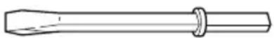
(1) Cold Chisel
Overall Length: 410, 520 mm
○Crushing
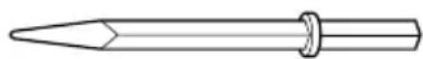
(1) Bull Point
Overall Length: 410 mm
○Scooping Work
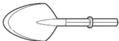
natural_image
Line drawing of a tool with a curved blade and handle (no text or symbols)(1) Scoop
Overall Length: 546 mm
○Grease
500g (in a can)
70g (in a tube)
30g (in a tube)
Optional accessories are subject to change without notice.
APPLICATIONS
This Demolition Hammer should be applied to demolishing concrete, chiseling off concrete, grooving, bar cutting installation of piping and wiring, sanitary facility installation, machinery installation, water supply and drainage work, interior jobs, harbor facilities and other civil engineering works.
PRIOR TO OPERATION
1. Power source
Ensure that the power source to be utilized conforms to the power requirements specified on the product nameplate of this Demolition Hammer.
2. Power switch
Ensure that the power switch is in the OFF position. If the plug is connected to a receptacle while the power switch is in the ON position, this Demolition Hammer will start operating immediately, which could cause a serious accident.
3. Extension cord
When the work area is remote from the power source, use an extension cord of sufficient thickness and rated capacity. The extension cord should be kept as short as practicable.
4. Mounting an accessory, such as a bull point, a cutter, etc.
CAUTION:
Be sure to switch OFF and disconnect the attachment plug from the receptacle to avoid a serious accident. NOTE:
For accessories such as a bull point and a cutter, use only Hitachi genuine parts.
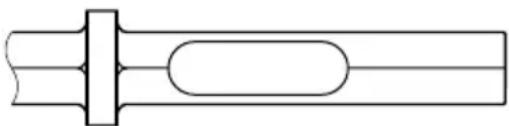
* It is possible to attach an accessory, such as a bull point, a cutter, etc., with any of the three types of the accessory shank portion shapes shown below.
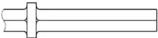
natural_image
Pure mechanical shaft diagram without any text, numbers, or symbolsAir Tool Shank Bit
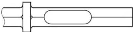
natural_image
Pure mechanical shaft diagram without any text, numbers, or symbolsStandard Hex. Shank Bit (Combo Type)
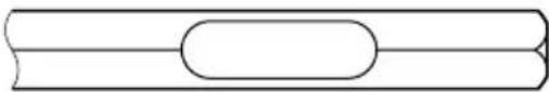
natural_image
Pure diagram of a cylindrical object with a horizontal line and rounded ends, no text or symbols present.Retaining Groove Bit without Collar
○Mounting air tool shank and standard hexagonal shank tools.
(1) Clean, then smear the accessory shank portion grease or machine oil.
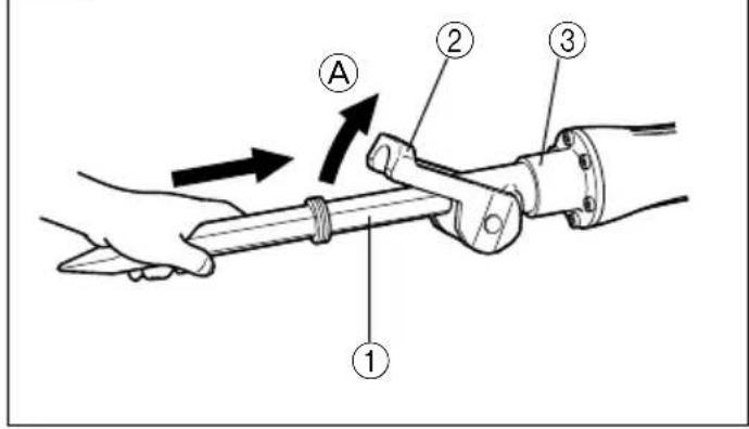
(2) Move the retainer to open position Ⓐ and seat the accessory, such as a bull point, a cutter, etc., in the hexagonal hole in the front cover (See Fig.1).
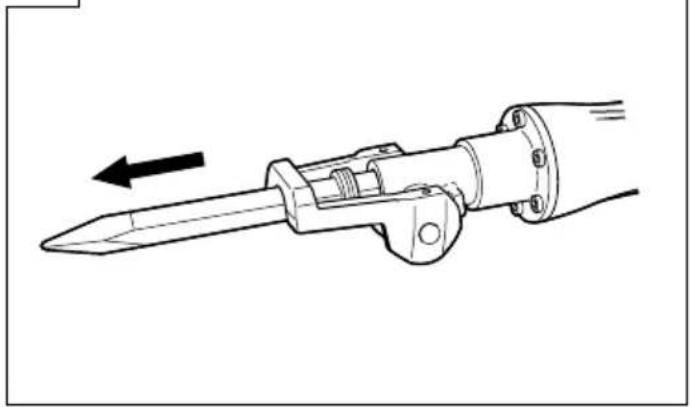
(3) Clamp the accessory into place by bringing the retainer to the clamp position. To make sure that the accessory is properly mounted, pull on the accessory. (Fig. 2)
○Mounting standard hexagonal shanks and retaining groove shanks without collars.
(1) Clean, then smear the accessory shank portion with grease or machine oil.
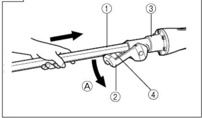
(2) Move the retainer to position Ⓐ. Align the accessory shank portion so that its recessed portion is under clamp and seat the accessory, such as a bull point, a cutter, etc., in the hexagonal hole in the front cover (See Fig. 3).
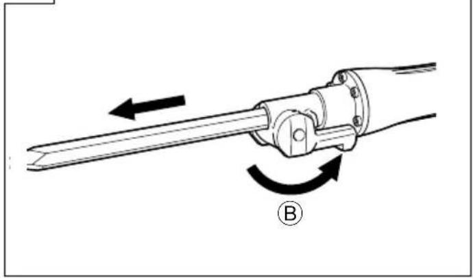
(3) Clamp the accessory into place by bringing the retainer to clamp position Ⓑ. To make sure that the accessory is properly mounted, pull on the accessory. (Fig. 4)
NOTE:
When removing the accessory, such as a bull point, a cutter, etc., carry out the above procedures in reverse.
HOW TO USE THE DEMOLITION HAMMER
- Squeeze the trigger switch after applying the tip of the bit to the crushing position.
In some cases, it is necessary to punch the tip of the bit against the crushing position forcibly in order to begin the striking motion.
This is not due to malfunction of the power tool. It means that the safe guard mechanism against no-load striking is working.
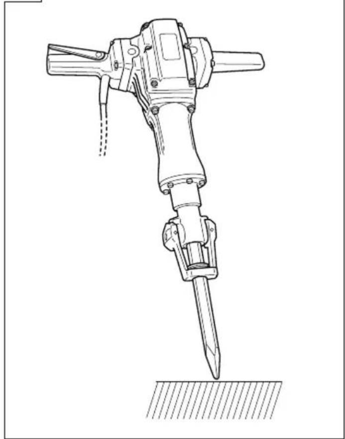
- Operate this Demolition Hammer by utilizing its empty weight. The performance will not be better even if it is pressed or thrust forcibly against the work surface. Hold this Demolition Hammer with a force just sufficient to counteract the reaction. (Fig. 5)
GREASE REPLACEMENT
This Demolition Hammer is of full air-tight construction to protect against dust and to prevent lubricant leakage. Therefore, this Demolition Hammer can be used without lubrication for long periods. Replace the grease as described below.
Grease Replacement Period
After purchase, replace grease after every 6 months of usage. Ask for grease replacement at the nearest authorized Service Center.
MAINTENANCE AND INSPECTION
CAUTION:
Be sure to switch OFF and disconnect the attachment plug from the receptacle to avoid a serious accident.
1. Inspecting this Demolition Hammer
Since use of a dull accessory, such as a bull point, a cutter, etc. will degrade efficiency and cause possible motor malfunction, sharpen or replace with a new one as soon as abrasion is noted.
2. Inspecting the mounting screws:
Regularly inspect all mounting screws and ensure that they are properly tightened. Should any of the screws be loose, retighten them immediately. Failure to do so could result in serious hazard.
3. Inspecting the retainer (Fig. 1, Fig. 2)
The retainer may become loose due to excessive use. Always, pay attention to its proper functioning to securely hold the accessory shank portion. If any wear and tear is found, bring this Demolition Hammer to an authorized service center for maintenance service.
4. Maintenance of the motor
The motor unit winding is the very "heart" of the power tool. Exercise due care to ensure the winding does not become damaged and/or wet with oil or water.
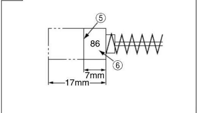
5. Inspecting the carbon brushes (Fig. 6)
The Motor employs carbon brushes which are consumable parts. When they become worn to or near the "wear limit", it results in motor trouble. When an auto-stop carbon brush is equipped, the motor will stop automatically. At that time, replace both carbon brushes with new ones which have the same carbon brush Numbers shown in the Fig. 6. In addition, always keep carbon brushes clean and ensure that they slide freely within the brush holders.
6. Replacing carbon brushes:
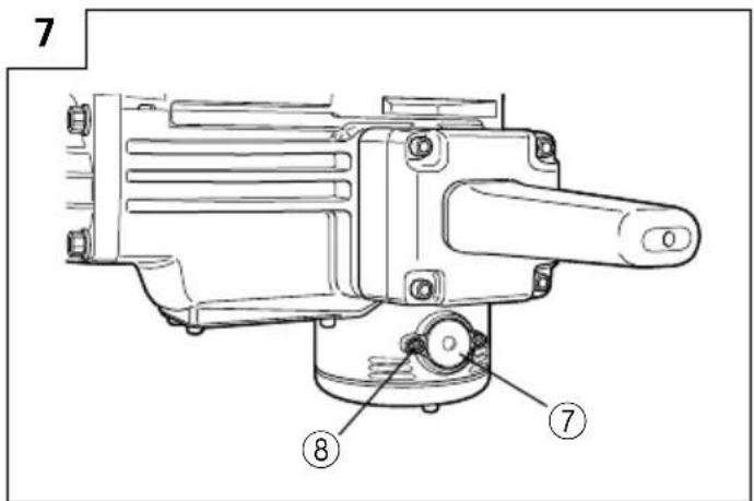
Loosen the screws (Hexagon socket hd. bolt M4×12) of the cap covers, then remove the cap covers (Fig. 7). After removing the brush caps, the carbon brushes can be removed.
After replacing the carbon brushes, tighten the brush caps, then mount the cap covers securely.
7. Service parts list
A: Item No.
B: Code No.
C: No. Used
D: Remarks
CAUTION
Repair, modification and inspection of Hitachi Power Tools must be carried out by an Authorized Service Center.
This Parts List will be helpful if presented with the power tool to the Authorized Service Center when requesting repair or other maintenance.
In the operation and maintenance of power tools, the safety regulations and standards prescribed in each country must be observed.
MODIFICATIONS
Hitachi Power Tools are constantly being improved and modified to incorporate the latest technological advancements.
Accordingly, some parts (i.e. code numbers and/or design) may be changed without prior notice.
GUARANTEE
We guarantee Hitachi Power Tools in accordance with statutory/country specific regulation. This guarantee does not cover defects or damage due to misuse, abuse, or normal wear and tear. In case of complaint, please send the Power Tool, undismantled, with the GUARANTEE CERTIFICATE found at the end of this Handling instruction, to a Hitachi Authorized Service Center.
NOTE
Due to HITACHI's continuing program of research and development, the specifications herein are subject to change without prior notice.
IMPORTANT
Correct connection of the plug
The wires of the main lead are coloured in accordance with the following code:
Blue: — Neutral
Brown: — Live
As the colours of the wires in the main lead of this power tool may not correspond with the coloured markings identifying the terminals in your plug proceed as follows: The wire coloured blue must be connected to the terminal marked with the letter N or coloured black. The wire coloured brown must be connected to the terminal marked with the letter L or coloured red. Neither core must be connected to the each terminal.
NOTE
This requirement is provided according to BRITISH STANDARD 2769: 1984.
Therefore, the letter code and colour code may not be applicable to other markets except The United Kingdom.
Information concerning vibration
Vibration total values (triax vector sum) determined according to EN60745.
Chiselling:
Vibration emission value ah , Cheq = 19.8 m/s ^2
Uncertainty K = 3.8 m/s²
The declared vibration total value has been measured in accordance with a standard test method and may be used for comparing one tool with another.
It may also be used in a preliminary assessment of exposure.
WARNING
○The vibration emission during actual use of the power tool can differ from the declared total value depending on the ways in which the tool is used.
○Identify safety measures to protect the operator that are based on an estimation of exposure in the actual conditions of use (taking account of all parts of the operating cycle such as the times when the tool is switched off and when it is running idle in addition to the trigger time).
natural_image
Simple line drawing of a spatula with a handle and pointed tip, labeled (1) Spaten (no text or symbols on the diagram itself)(1) Spaten
Gesamtlänge: 546 mm
○Schmierfett
500 g (Dose)
70 g (in Tube)
30 g (in Tube)
natural_image
Pure mechanical shaft diagram without any text, numbers, or symbolsnatural_image
Pure technical line drawing of a mechanical shaft or rod with no text, numbers, or symbolsnatural_image
Pure diagram of a cylindrical object with a horizontal bar and rounded ends, no text or symbols present.natural_image
Simple line drawing of a scoop with a pointed tip and handle (no text or symbols)(1) Scoop
natural_image
Pure mechanical shaft diagram without any text, numbers, or symbolsnatural_image
Pure mechanical shaft diagram without any text, numbers, or symbolsnatural_image
Pure diagram of a cylindrical object with a horizontal line and rounded ends, no text or symbols present.natural_image
Line drawing of a pipette with a pointed tip and handle (no text or symbols)(1) Paletta
natural_image
Pure mechanical shaft diagram without any text, numbers, or symbolsnatural_image
Pure technical line drawing of a mechanical component with no text or symbolsnatural_image
Pure diagram of a cylindrical object with a horizontal bar and rounded ends, no text or symbols present.natural_image
Line drawing of a snijder tool with handle and pointed tip (no text or symbols)(1) Snijder
Totale lengte: 410, 520 mm
Breedte: 75 mm
natural_image
Simple line drawing of a spoon or plunger with label (1) Schep, no other text or symbols present.(1) Schep
Totale lengte: 546 mm
○Grease
natural_image
Pure technical line drawing of a mechanical shaft or rod (no text or symbols)Pneumatisch gereedschap stift bit
natural_image
Pure mechanical shaft diagram without any text, numbers, or symbolsnatural_image
Pure diagram of a cylindrical object with a horizontal line and rounded ends, no text or symbols present.natural_image
Simple line drawing of a mechanical tool or tool with a pointed tip and cylindrical end (no text or symbols)(1) Cargadora
Largo total: 410, 520 mm
Anchura: 75 mm
natural_image
Simple line drawing of a Cuchara tool with a pointed tip and handle (no text or symbols on the diagram itself)Largo total: 546 mm
○Grasa
500 g (en una lata)
70 g (en un tubo)
30 g (en un tobo)
natural_image
Pure mechanical shaft diagram without any text, numbers, or symbolsnatural_image
Pure mechanical component diagram without any text, numbers, or symbolsnatural_image
Pure diagram of a cylindrical object with a horizontal line and rounded ends, no text or symbols present.natural_image
Line drawing of a mechanical tool labeled (1) Fresa, showing a tapered blade and shaft (no text or symbols on the object itself)natural_image
Line drawing of a stylized tool or plow with a pointed tip and handle (no text or symbols)(1) Pá
natural_image
Pure technical line drawing of a mechanical shaft or rod (no text or symbols)natural_image
Pure mechanical shaft diagram without any text, numbers, or symbolsnatural_image
Pure diagram of a cylindrical object with a horizontal line and rounded ends, no text or symbols present.natural_image
Line drawing of a pipette with a pointed tip and handle (no text or symbols)(1) φτιάρι
natural_image
Pure technical line drawing of a mechanical shaft or rod (no text or symbols)natural_image
Pure mechanical shaft diagram without any text, numbers, or symbolsnatural_image
Pure diagram of a cylindrical object with a horizontal line and rounded ends, no text or symbols present.natural_image
Line drawing of a quill pen with inkwell (no text or symbols)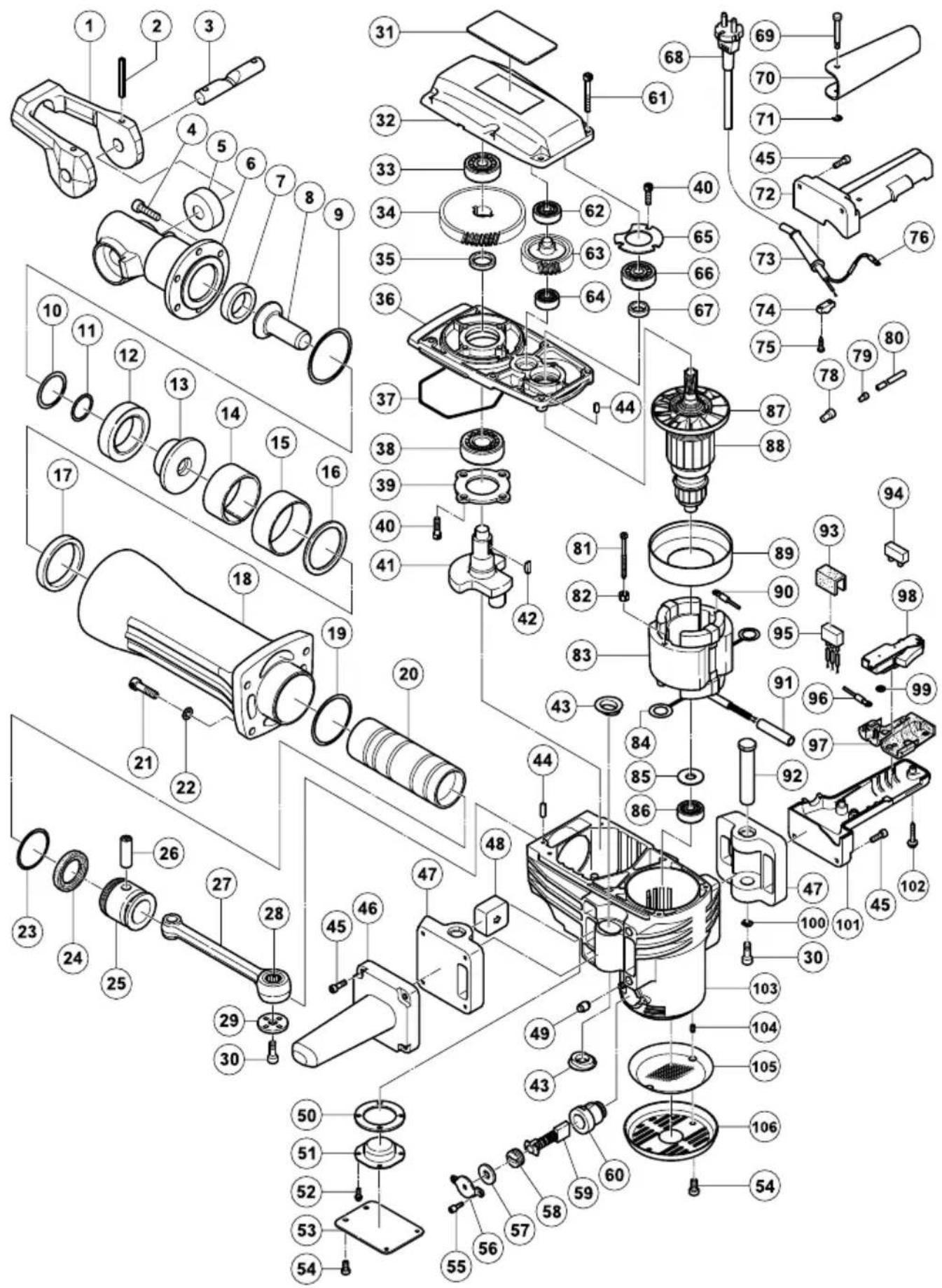
| A | B | C | D |
| 1 318-221 | 1 | ||
| 2 994-416 | 2 D6 × 55 | ||
| 3 318-222 | 1 | ||
| 4 306-437 | 6 M8 × 30 | ||
| 5 305-621 | 2 | ||
| 6 318-223 | 1 | ||
| 7 996-369 | 1 | ||
| 8 996-367 | 1 | ||
| 9 998-428 | 1 | ||
| 10 998-417 | 1 | ||
| 11 998-419 | 1 | ||
| 12 998-433 | 1 | ||
| 13 998-418 | 1 | ||
| 14 956-963 | 1 | ||
| 15 956-962 | 1 | ||
| 16 956-961 | 1 | ||
| 17 956-960 | 1 | ||
| 18 320-489 | 1 | ||
| 19 956-996 | 1 1AS-60 | ||
| 20 956-958 | 1 | ||
| 21 306-163 | 4 M8 × 35 | ||
| 22 949-433 | 4 M8 | ||
| 23 998-414 | 1 | ||
| 24 998-415 | 1 | ||
| 25 998-413 | 1 | ||
| 26 944-928 | 1 | ||
| 27 998-434 | 1 "28" | ||
| 28 944-921 | 1 | ||
| 29 956-955 | 1 | ||
| 30 996-364 | 3 M8 × 16 | ||
| 31 ———— | 1 | ||
| 32 319-360 | 1 | ||
| 33 630-2VV | 1 6302VVCMPS2L | ||
| 34 944-916 | 1 | ||
| 35 944-915 | 1 | ||
| 36 998-412 | 1 | ||
| 37 957-143 | 1 | ||
| 38 620-5DD | 1 6205DDCMPS2L | ||
| 39 956-949 | 1 | ||
| 40 990-079 | 7 M5 × 16 | ||
| 41 998-430 | 1 | ||
| 42 956-850 | 2 4 × 16 | ||
| 43 318-655 | 4 | ||
| 44 944-918 | 2 D5 × 15.8 | ||
| 45 993-496 | 8 M6 × 30 | ||
| 46 305-633 | 1 | ||
| 47 319-365 | 2 | ||
| 48 319-364 | 2 | ||
| 49 310-124 | 4 | ||
| 50 956-969 | 1 | ||
| 51 998-416 | 1 | ||
| 52 987-203 | 4 M4 × 12 | ||
| 53 998-417 | 1 | ||
| 54 991-690 | 6 M5 × 12 | ||
| 55 983-162 | 4 M4 × 12 | ||
| 56 956-972 | 2 | ||
| 57 944-960 | 2 | ||
| 58 940-540 | 2 | ||
| 59 999-086 | 2 | ||
| 60 956-984 | 2 |
| A | B | C | D |
| 61 | 986-940 | 6 M6 × 45 | |
| 62 | 620-1VV | 1 6201VVCMPS2L | |
| 63 | 956-948 | 1 | |
| 64 | 600-14VV | 1 6001VVCMPS2L | |
| 65 | 944-911 | 1 | |
| 66 | 620-3DD | 1 6203DDCMPS2L | |
| 67 | 944-907 | 1 | |
| 68 | 1 500-390Z | 1 | |
| 68 | 2 500-644Z | 1 "GBR (110V)" | |
| 68 | 3 500-450Z | 1 "GBR (230V)" | |
| 68 | 4 500-247Z | 1 "SAF" | |
| 68 | 5 500-408Z | 1 "AUS" | |
| 69 | 992-870 | 1 | |
| 70 | 992-869 | 1 | |
| 71 | 968-643 | 1 | |
| 72 | 305-636 | 1 | |
| 73 | 1 958-049 | 1 D8.2 | |
| 73 | 2 940-778 | 1 D10.7 | |
| 74 | 960-266 | 1 | |
| 75 | 982-095 | 2 D4 × 20 | |
| 76 | 1 980-063 | 1 | |
| 76 | 2 930-804 | 1 "GBR (110V)" | |
| 78 | 959-141 | 2 50092 | |
| 79 | 959-140 | 1 50091 | |
| 80 | 996-438 | 2 | |
| 81 | 960-251 | 2 D5 × 65 | |
| 82 | 956-764 | 2 | |
| 83 | 1 340-488C | 1 110V "84" | |
| 83 | 2 340-488E | 1 230V "84" | |
| 83 | 3 340-488F | 1 240V "84" | |
| 84 | 945-932 | 2 | |
| 85 | 944-954 | 1 | |
| 86 | 620-1DD | 1 6201DDCMPS2L | |
| 87 | 996-370 | 1 | |
| 88 | 1 360-286C | 1 110V-115V "87" | |
| 88 | 2 360-286E | 1 220V-230V "87" | |
| 88 | 3 360-286F | 1 240V "87" | |
| 89 | 306-098 | 1 | |
| 90 | 986-277 | 1 | |
| 91 | 319-363 | 1 | |
| 92 | 319-366 | 2 | |
| 93 | 930-153 | 1 | |
| 94 | 938-307 | 1 | |
| 95 | 317-491 | 1 | |
| 96 | 1 981-974 | 1 | |
| 96 | 2 306-681 | 1 "GBR" | |
| 97 | 990-082 | 1 | |
| 98 | 992-891 | 1 | |
| 99 | 949-423 | 1 M4 | |
| 100 | 319-367 | 2 | |
| 101 | 305-631 | 1 | |
| 102 | 301-653 | 2 D4 × 20 | |
| 103 | 319-361 | 1 "60, 104" | |
| 104 | 938-477 | 2 M5 × 8 | |
| 105 | 319-362 | 1 | |
| 106 | 306-099 | 1 |
natural_image
Line drawing of a quill pen with inkwell (no text or symbols)| English | Nederlands | ||
| GUARANTEE CERTIFICATE1Model No.2Serial No.3Date of Purchase4Customer Name and Address5Dealer Name and Address(Please stamp dealer name and address) | GARANTIEBEWIJS1Modelnummer2Serienummer3Datum van aankoop4Naam en adres van de gebruiker5Naam en adres van de handelaar(Stempel a.u.b. naam en adres vande de handelaar) | ||
| Deutsch | Español | ||
| GARANTIESCHEIN1Modell-Nr.2Serien-Nr.3Kaufdaturn4Name und Anschrift des Kunden5Name und Anschrift des Händlers(Bitte mit Namen und Anschrift des Handlers abstempeln) | CERTIFICADO DE GARANTIA1Número de modelo2Número de serie3Fecha de adquisición4Nombre y dirección del cliente5Nombre y dirección del distribudor(Se ruega poner el sellú del distribudor con su nombre y dirección) | ||
| Français Português | |||
| CERTIFICAT DE GARANTIE1No. de modèle2No. de série3Date d'achat4Nom et adresse du client5Nom et adresse du revendeur(Cachet portant le nom et l'adresse du revendeur) | CETTIFICADO DE GARANTIA1Número do modelo2Número do série3Data de compra4Nome e morada do cliente5Nome e morada do distribuidor(Por favor, carímbe o nome e morada do distribuidor) | ||
| Italiano Ελληνικά | |||
| CERTIFICATO DI GARANZIA1Modello2N° di serie3Data di acquisto4Nome e indirizzo dell'acquirente5Nome e indirizzo del rivenditore(Si prega di apporre il timbro con questi dati) | ΠΙΣΤΟΠΟΙΗΤΙΚΟ ΕΓΓΥΗΣΗΣ1Αρ. Μοντέλου2Αύξων Αρ.3Ημερομηνία αγοράς4Όνομα και διεύθυνση πελάτη5Όνομα και διεύθυνση μεταπωλητή(Παρακαλούμε να χρησιμοποιηθεί σφραγίδα) | ||
HITACHI
| 1 | |
| 2 | |
| 3 | |
| 4 | |
| 5 |
Hitachi Koki
Hitachi Power Tools Europe GmbH
Siemensring 34, 47877 willich 1, F. R. Germany
Tel: +49 2154 49930
Fax: +49 2154 499350
URL: http://www.hitachi-powertools.de
Hitachi Power Tools Netherlands B. V.
Brabanthaven 11, 3433 PJ Nieuwegein, The Netherlands
Tel: +31 30 6084040
Fax: +31 30 6067266
URL: http://www.hitachi-powertools.nl
Hitachi Power Tools (U. K.) Ltd.
Precedent Drive, Rooksley, Milton Keynes, MK 13, 8PJ, United Kingdom
Tel: +44 1908 660663
Fax: +44 1908 606642
URL: http://www.hitachi-powertools.co.uk
Hitachi Power Tools France S. A. S.
Prac del' Eglantier 22, rue des Crerisiers Lisses, C. E. 1541,
91015 EVRY CEDEX, France
Tel: +33 1 69474949
Fax: +33 1 60861416
URL: http://www.hitachi-powertools.fr
Hitachi Power Tools Belgium N.V. / S.A.
Koningin Astridlaan 51, 1780 Wemmel, Belgium
Tel: +32 2 460 1720
Fax: +32 2 460 2542
URL http://www.hitachi-powertools.be
Hitachi Fercad Power Tools Italia S.p.A
Via Retrone 49-36077, Altavilla Vicentina (VI), Italy
Tel: +39 0444 548111
Fax: +39 0444 548110
URL: http://www.hitachi-powertools.it
Hitachi Power Tools Iberica, S.A.
C / Migjorn, s/n, Poligono Norte, 08226 Terrassa, Barcelona, Spain
Tel: +34 93 735 6722
Fax: +34 93 735 7442
URL: http://www.hitachi-powertools.es
Clonshaugh Business & Technology Park, Dublin 17, Ireland
Representative office in Europe
Hitachi Power Tools Europe GmbH
Siemensring 34, 47877 Willich 1, F. R. Germany
Head office in Japan
Hitachi Koki Co., Ltd.
Shinagawa Intercity Tower A, 15-1, Konan 2-chome, Minato-ku, Tokyo, Japan
CE
-
- 2012
John de Loughy
Mr. John de Loughry
European Standards and Compliance Manager
-
- 2012
F. Tashimo
F. Tashimo
Vice-President & Director
- GENERAL POWER TOOL SAFETY WARNINGS
- WARNING
- Save all warnings and instructions for future reference.
- 1) Work area safety
- 2) Electrical safety
- 3) Personal safety
- 4) Power tool use and care
- 5) Service
- PRECAUTION
- DEMOLITION HAMMER SAFETY WARNINGS
- Wear ear protectors.
- Use auxiliary handle(s), if supplied with the tool.
- STANDARD ACCESSORIES
- OPTIONAL ACCESSORIES (sold separately)
- APPLICATIONS
- PRIOR TO OPERATION
- Power source
- Power switch
- Extension cord
- Mounting an accessory, such as a bull point, a cutter, etc.
- CAUTION:
- NOTE:
- HOW TO USE THE DEMOLITION HAMMER
- GREASE REPLACEMENT
- Grease Replacement Period
- MAINTENANCE AND INSPECTION
- Inspecting this Demolition Hammer
- Inspecting the mounting screws:
- Inspecting the retainer (Fig. 1, Fig. 2)
- Maintenance of the motor
- Inspecting the carbon brushes (Fig. 6)
- Replacing carbon brushes:
- Service parts list
- CAUTION
- MODIFICATIONS
- GUARANTEE
- NOTE
- IMPORTANT
- Information concerning vibration
- ○Grease
- Hitachi Power Tools Europe GmbH
- Hitachi Power Tools Netherlands B. V.
- Hitachi Power Tools (U. K.) Ltd.
- Hitachi Power Tools France S. A. S.
- Hitachi Power Tools Belgium N.V. / S.A.
- Hitachi Fercad Power Tools Italia S.p.A
- Hitachi Power Tools Iberica, S.A.
- Hitachi Koki Co., Ltd.
Brand : HITACHI
Model : H 70SD
Category : Hammer