
H 45SB2 - Hammer HITACHI - Free user manual and instructions
Find the device manual for free H 45SB2 HITACHI in PDF.


| Product type | Electric demolition hammer |
| Brand | Hitachi |
| Model | H 45SB2 |
| Weight | 4.8 kg (10.6 lbs) |
| Power supply | 115 V ~, 60 Hz, single phase |
| Rated current | 8 A |
| Number of impacts at full load | 3000 / min |
| Motor type | Series commutator motor, double insulation |
| Polarized plug | Yes (one wider blade) |
| Main applications | Concrete breaking, chipping, grooving, rod cutting, pile driving |
| Standard accessories | Case, side handle, 6 mm Allen key, 5 mm Allen key |
| Optional accessories | Chipping (300 mm), grooving (300/460 mm), asphalt cutting (12"), digging, grease A |
| Lubrication | Hitachi grease A, replacement every 6 months |
| Brush maintenance | Carbon brushes with automatic stop; replace by part number 73 |
| User protection | Safety glasses, ear protection, gloves recommended |
| Electrical safety | Double insulation, do not use in wet conditions |
| Spare parts | Use exclusively original Hitachi parts |
| Repairs | Carried out only by an authorized Hitachi service center |
Frequently Asked Questions - H 45SB2 HITACHI
User questions about H 45SB2 HITACHI
0 question about this device. Answer the ones you know or ask your own.
Ask a new question about this device
Download the instructions for your Hammer in PDF format for free! Find your manual H 45SB2 - HITACHI and take your electronic device back in hand. On this page are published all the documents necessary for the use of your device. H 45SB2 by HITACHI.
USER MANUAL H 45SB2 HITACHI
natural_image
Line drawing of a mechanical device with a long spoke and handle (no text or symbols)INSTRUCTION MANUAL AND SAFETY INSTRUCTIONS
WARNING
Improper and unsafe use of this power tool can result in death or serious bodily injury!
This manual contains important information about product safety. Please read and understand this manual before operating the power tool. Please keep this manual available for others before they use the power tool.
MODE D'EMPLOI ET INSTRUCTIONS DE SECURITE
⚠ AVERTISSEMENT
IMPORTANT SAFETY INSTRUCTIONS
FOR USING ALL POWER TOOLS 4
IMPORTANT SAFETY INSTRUCTIONS
FOR USE OF THE DEMOLITION HAMMER... 8
REPLACEMENT PARTS 8
POLARIZED PLUGS 8
USE OF EXTENSION CORD 9
HOW TO REPLACE GREASE 15
MAINTENANCE AND INSPECTION.... 16
SERVICE AND REPAIRS 17
PARTS LIST 48
TABLE DES MATIERES
Français
Page
INFORMATIONS IMPORTANTES .... 18
SIGNIFICATION DES MOTS D'AVERTISSEMENT .. 18
SECURITE
CONSIGNES DE SECURITE IMPORTANTES POUR
L'UTILISATION DE TOUS LES OUTILS ELECTRIQUES... 19
CONSIGNES DE SECURITE IMPORTANTES
POUR L'UTILISATION DU MARTEAU PIQUEUR .. 23
PIECES DE RECHANGE 23
FICHE POLARISEES 23
CORDON DE RALLONGE 24
DOUBLE ISOLATION POUR UN
FONCTIONNEMENT PLUS SUR ..... 25
Page
UTILISATION ET ENTRETIEN
NOM DES PIECES 26
FICHE TECHNIQUE 26
ACCESSOIRES 27
ACCESSOIRES STANDARD ..... 27
ACCESSOIRES EN OPTION ...... 27
APPLICATIONS 28
Read and understand all of the operating instructions, safety precautions and warnings in the Instruction Manual before operating or maintaining this power tool.
Most accidents that result from power tool operation and maintenance are caused by the failure to observe basic safety rules or precautions. An accident can often be avoided by recognizing a potentially hazardous situation before it occurs, and by observing appropriate safety procedures.
Basic safety precautions are outlined in the “SAFETY” section of this Instruction Manual and in the sections which contain the operation and maintenance instructions.
Hazards that must be avoided to prevent bodily injury or machine damage are identified by WARNINGS on the power tool and in this Instruction Manual.
Never use this power tool in a manner that has not been specifically recommended by HITACHI, unless you first confirm that the planned use will be safe for you and others.
MEANINGS OF SIGNAL WORDS
WARNING indicates a potentially hazardous situations which, if ignored, could result in serious personal injury.
CAUTION indicates a hazardous situations which, if ignored, could result in moderate personal injury, or could cause machine damage.
NOTE emphasizes essential information.
SAFETY
IMPORTANT SAFETY INSTRUCTIONS FOR USING ALL POWER TOOLS

WARNING: Death or serious bodily injury could result from improper or unsafe use of power tools. To avoid these risks, follow these basic safety instructions:
READ ALL INSTRUCTIONS
Never place your hands, fingers or other body parts near the tool's moving parts.
- NEVER OPERATE WITHOUT ALL GUARDS IN PLACE.
Never operate this tool without all guards or safety features in place and in proper working order. If maintenance or servicing requires the removal of a guard or safety feature, be sure to replace the guard or safety feature before resuming operation of the tool.
- ALWAYS WEAR EYE AND EAR PROTECTOR.
Protect yourself from flying or expelled wood chips, metal particles or other debris by using protective goggles or equivalent eye protector. Wear ear protector to protect yourself from excessive noise.
- PROTECT YOURSELF AGAINST ELECTRIC SHOCK.
Prevent body contact with grounded surfaces such as pipes, radiators, ranges and refrigeration enclosures. Never operate the tool in damp or wet locations.
- DISCONNECT TOOLS.
Never leave the tool connected to a power source. Always disconnect the tool from its power source before servicing, inspecting, maintaining, cleaning and before changing or checking any parts.
- AVOID UNINTENTIONAL STARTING.
Don't carry the tool while it is connected to its power source. Don't carry the tool with your finger near the power switch. Be sure the power switch is in the “off” position before connecting the tool to its power source.
- STORE TOOL PROPERLY.
When not in use, the tool should be stored in a dry place. Keep out of reach of children. Lock-out the storage area.
- KEEP WORK AREA CLEAN.
Cluttered areas and benches invite injuries. Clear all work areas and work benches of unnecessary tools, debris, furniture, etec.
9. CONSIDER WORK AREA ENVIRONMENT.
Don't expose power tools to rain. Don't use power tools in damp or wet locations. Keep work area well lit and well ventilated.
Don't use tool in presence of flammable liquids or gases.
Power tools produce sparks during operation. They also spark when switching ON/OFF. Never use power tools in sites containing lacquer, paint, benzine, thinner, gasoline, gases, adhesive agents, and other materials which are combustible or explosive.
10. KEEP CHILDREN AWAY.
Do not let visitors contact tool or extension cord.
All visitors should be kept safely away from work area.
11. DON'T FORCE TOOL.
It will do the job better and safer at the rate for which it was intended.
12. USE RIGHT TOOL.
Don't force small tool or attachment to do the job of a heavy-duty tool.
Don't use tool for purpose not intended—for example—don't use circular saw for cutting tree limbs or logs.
13. DRESS PROPERLY.
Do not wear loose clothing or jewelry. They can be caught in moving parts.
Rubber gloves and non-skid footwear are recommended when working outdoors.
Wear protective hair covering to contain long hair.
14. USE FACE, DUST MASK OR RESPIRATOR IF OPERATION IS DUSTY.
All persons in the area where power tools are being operated should also wear face, dust mask or respirator.
15. DON'T ABUSE CORD.
Never carry tool by cord or yank it to disconnect from receptacle.
Keep cord from heat, oil and sharp edges.
16. SECURE WORK.
Use clamps or a vise to hold work. It's safer than using your hand and it frees both hands to operate tool.
17. DON'T OVERREACH.
Keep proper footing and balance at all times.
18. MAINTAIN TOOLS WITH CARE.
Keep tools sharp and clean for better and safer performance.
Follow instructions for lubricating and changing accessories.
Inspect tool cords periodically and if damaged, have repaired by an authorized service center. Inspect extension cords periodically and replace if damaged.
Keep handles dry, clean, and free from oil and grease.
19. REMOVE ADJUSTING KEYS AND WRENCHES.
Keys and adjusting wrenches remove from tool before turning it on.
20. OUTDOOR USE EXTENSION CORD.
When tool is used outdoors, use only extension cord intended for use outdoors and so marked.
21. STAY ALERT.
Watch what you are doing. Use common sense. Do not operate tool when you are tired.
Tools should never be used by you if you are under the influence of alcohol, drugs or medication that makes you drowsy.
22. CHECK DAMAGED PARTS.
Before further use of the tool, a guard or other part that is damaged should be carefully checked to determine that it will operate properly and perform its intended function. Check for alignment of moving parts, binding of moving parts, breakage of parts, mounting, and any other conditions that may affect its operation.
A guard or other part that is damaged should be properly repaired or replaced by an authorized service center unless otherwise indicated elsewhere in this Instruction Manual.
Have defective switches replaced by the authorized service center.
Do not use tool if switch does not turn it on and off.
23. NEVER USE A POWER TOOL FOR APPLICATIONS OTHER THAN THOSE SPECIFIED.
Never use a power tool for applications other than those specified in the Instruction Manual.
24. HANDLE TOOL CORRECTLY.
Operate the tool according to the instructions provided herein. Do not drop or throw the tool. Never allow the tool to be operated by children, individuals unfamiliar with its operation or unauthorized personnel.
25. CHECK FOR LIVE WIRES.
Avoid the risk of severe electrical shock by checking for live electrical wires that may be buried in walls, floors or ceilings. The wires should be de-energized before work begins.
26. KEEP ALL SCREWS, BOLTS AND COVERS TIGHTLY IN PLACE.
Keep all screws, bolts, and plates tightly mounted. Check their condition periodically.
27. DO NOT USE POWER TOOLS IF THE PLASTIC HOUSING OR HANDLE ARE CRACKED.
Cracks in the tool's housing or handle can lead to electric shock. Such tools should not be used until repaired.
28. BLADES AND ACCESSORIES MUST BE SECURELY MOUNTED TO THE TOOL.
Prevent potential injuries to yourself or others. Blades, cutting implements and accessories which have been mounted to the tool should be secure and tight.
29. KEEP MOTOR AIR VENT CLEAN.
The tool's motor air vent must be kept clean so that air can freely flow at all times. Check for dust build-up frequently.
30. OPERATE POWER TOOLS AT THE RATED VOLTAGE.
Operate the power tool at voltages specified on their nameplates.
If using the power tool at a higher voltage than the rated voltage, it will result in abnormally fast motor revolution and may damage the unit and burn out the motor.
31. NEVER USE A TOOL WHICH IS DEFECTIVE OR OPERATING ABNORMALLY
If the tool appears to be operating unusually, making abnormal noises, or otherwise appears defective, stop using it immediately and arrange for repairs by a Hitachi authorized service center.
Don't leave tool until it comes to a complete stop.
33. CAREFULLY HANDLE POWER TOOLS.
Should a power tool be dropped or struck against hard materials inadvertently it may be deformed, cracked, or damaged.
34. DO NOT WIPE PLASTIC PARTS WITH SOLVENT.
Solvents such as gasoline, thinner, benzine, carbon tetrachloride, and alcohol may damage and crack plastic parts. Do not wipe them with such solvents.
Wipe plastic parts with a soft cloth lightly dampened with soapy water and dry thoroughly.
35. USE ONLY GENUINE HITACHI REPLACEMENT PARTS.
Replacement parts not manufactured by Hitachi may void your warranty and can lead to malfunction and resulting injuries. Genuine Hitachi parts are available from your dealer.
IMPORTANT SAFETY INSTRUCTIONS FOR USE OF THE DEMOLITION HAMMER

WARNING: Death or serious bodily injury could result from improper or unsafe use of the demolition hammer. To avoid these risks, follow these basic safety instructions:
- NEVER touch the tool bit with bare hands after operation.
- NEVER wear gloves made of stuff liable to roll up such as cotton, wool, cloth or string, etc.
- ALWAYS attach the side handle and securely grip the Demolition Hammer.
- ALWAYS wear eye and ear protectors during operation.
- ALWAYS be careful with buried object such as an underground wiring. Touching these active wiring or electric cable with this tool, you may receive an electric shock. Comfirm if there are any buried object such as electric cable within the wall, floor or ceiling where you are going to operate here after.
REPLACEMENT PARTS
When servicing use only identical replacement parts.
Repairs should be conducted only by a Hitachi authorized service center.
POLARIZED PLUGS
To reduce the risk of electric shock, this equipment has a polarized plug (one blade is wider than the other).
This plug will fit in a polarized outlet only one way.
If the plug does not fit fully in the outlet, reverse the plug.
If it still does not fit, contact a qualified electrician to install the proper outlet.
Do not change the plug in any way.
USE OF EXTENSION CORD
Make sure your extension cord is in good condition. When using an extension cord, be sure to use one heavy enough to carry the current your product will draw. An undersized cord will cause a drop in line voltage resulting in loss of power and overheating. Table shows the correct size to use depending on cord length and nameplate ampere rating. If in doubt, use the next heavier gage. The smaller the gage number, the heavier the cord.
MINIMUM GAGE FOR CORD SETS
| Total Length of Cord in Feet (Meter) | |||||
| 0 – 25 | 26 – 50 | 51 – 100 | 101 – 150 | ||
| (0 – 7.6) | (7.9 – 15.2) | (15.5 – 30.5) | (30.8 – 45.7) | ||
| Ampere Rating AWGMore Not MoreThan Than | |||||
| 0 | - | 6 | 1 | 8 | 1 |
| 6 – 10 18 | 16 | 14 | 12 | ||
| 10 – 12 | 16 | 16 | 14 | 12 | |
| 12 – 16 | 14 | 12 | Not Recommended | ||

WARNING: Avoid electrical shock hazard. Never use this tool with a damaged or frayed electrical cord or extension cord.
Inspect all electrical cords regularly. Never use in or near water or in any environment where electric shock is possible.
To ensure safer operation of this power tool, HITACHI has adopted a double insulation design. “Double insulation” means that two physically separated insulation systems have been used to insulate the electrically conductive materials connected to the power supply from the outer frame handled by the operator. Therefore, either the symbol “☐ or the words and “Double insulation” appear on the power tool or on the nameplate.
Although this system has no external grounding, you must still follow the normal electrical safety precautions given in this Instruction Manual, including not using the power tool in wet environments.
To keep the double insulation system effective, follow these precautions:
○Only HITACHI AUTHORIZED SERVICE CENTER should disassemble or assemble this power tool, and only genuine HITACHI replacement parts should be installed.
○Clean the exterior of the power tool only with a soft cloth moistened with soapy water, and dry thoroughly.
Never use solvents, gasoline or thinners on plastic components; otherwise the plastic may dissolve.
SAVE THESE INSTRUCTIONS AND MAKE THEM AVAILABLE TO OTHER USERS OF THIS TOOL!
The information contained in this Instruction Manual is designed to assist you in the safe operation and maintenance of the power tool.
Some illustrations in this Instruction Manual may show details or attachments that differ from those on your own power tool.
NAME OF PARTS

Fig. 1
SPECIFICATIONS
| Motor Single-Phase, Series Commutator Motor | |
| Power Source Single-Phase, 115V AC 60Hz | |
| Current 8A | |
| Full-load Impact Rate 3,000/min. | |
| Weight 10.6 lbs (4.8 kg) | |
ACCESSORIES

WARNING: Accessories for this power tool are mentioned in this Instruction Manual.
The use of any other attachment or accessory can be dangerous and could cause injury or mechanical damage.
STANDARD ACCESSORIES
(1)Case (Code No. 310131)....1
(2)Side Handle (Code No. 981870) ....1
(3)Allen Wrench (for 6mm screw) (Code No. 944459) ....1
(4)Allen Wrench (for 5mm screw) (Code No. 944458) ....1
OPTIONAL ACCESSORIES...... sold separately
○Cruching

natural_image
Technical line drawing of a pen and its mechanical device (no text or symbols)(1) Bull point
| Overall length | Code No. |
| 12" (300 mm) | 985383 |
○Groove digging and edging

natural_image
Technical line drawing of a mechanical component with a shaft and housing assembly (no text or symbols)(1) Cold chisel
| Overall length | Code No. |
| 12" (300 mm) | 985381 |
| 18" (460 mm) | 985382 |
○Asphalt cutting

natural_image
Technical line drawing of a mechanical component with a flanged shaft and a mounted device (no text or symbols)(1) Cutter
| Overall length | Width Code No. | |
| 12"(300 mm) | 1-1/2" (38 mm) | 985384 |
| 2" (50 mm) | 985385 |
○Scooping work

○Hammer grease A
30g (in a tube) (Code No. 981840)
70g(in a tube) (Code No. 308471)
NOTE:
Accessories are subject to change without any obligation on the part of the HITACHI.
APPLICATIONS
○Breaking concrete, chipping off concrete, grooving, bar cutting, and driving piles. (Application examples)
Installation of piping and wiring, sanitary facility installation, machinery installation, water supply and drainage work, interior jobs, harbor facilities and other civil engineering work.
PRIOR TO OPERATION
1. Power source
Ensure that the power source to be utilized conforms to the power source requirements specified on the product nameplate.
2. Power switch
Ensure that the switch is in the OFF position. If the plug is connected to a receptacle while the switch is in the ON position, the power tool will start operating immediately and can cause serious injury.
3. Extension cord
When the work area is far away from the power source, use an extension cord of sufficient thickness and rated capacity (refer to page 8). The extension cord should be kept as short as practicable.
⚠ WARNING: Damaged cord must be replaced or repaired.
4. Check the receptacle
If the receptacle only loosely accepts the plug, the receptacle must be repaired.
Consult an authorized electrician to make appropriate repairs.
If such a fautly receptacle is used, it may cause overheating, resulting in firing.
5. Confirming condition of the environment:
Confirm that the work site is placed under appropriate conditions conforming to prescribed precautions.
6. How to install tool
NOTE: For tools such as a bull point and a cold chisel, use only Hitachi genuine parts.
(1)Clean, then smear the tool shank with the grease (optional accessory).
(2) Pull the tool holder in the direction of arrow ① and rotate it in the direction of arrow ② (counterclockwise). Fully insert the tool shank into the hexagonal hole of the front cover. (Fig. 2)
(3) Return the tool holder to fix the tool.
NOTE: Remove in the reverse order for installation.
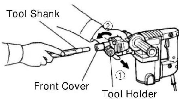
Fig. 2
HOW TO USE THE DEMOLITION HAMMER
- After placing the tip of the tool in the base hole, switch ON.
- By utilizing the empty weight of the machine and firmly hold the hammer with both hands, you can effectively control the subsequent recoil motion. Proceed at a moderate work-rate, applying too much force will impair efficiency.

natural_image
Line drawing of a hand holding a medical or robotic device with a tool, no text or symbols presentFig. 3

CAUTION: After long time of use, the front cover becomes hot. Therefore, be careful not to burn your hands.
HOW TO REPLACE GREASE
This hammer is full air-tight construction to protect against dust and to prevent lubricant leakage. Therefore, the hammer can be used without replenishing grease for long periods. Replace the grease as described below.
- Grease replacement period
After purchase, replace grease after every 6 months of usage. Ask for grease replacement at the nearest authorized HITACHI Service Center. Proceed for replacement of grease.
- Grease replacement

CAUTION:
Before replacing the grease, turn the power off and pull out the power plug.
(1) Remove the crank cover and thoroughly remove the old grease inside.
(2) Apply 0.7 oz (20g) of HITACHI Hammer Grease A (optional accessory, contained in tube) into the crank case.
(3) After replacing the grease, mount the crank cover securely.
NOTE:
○The Hitachi Hammer Grease A is of the low viscosity type. When the supplied grease tube is consumed, purchase from an Authorized Hitachi Service Agent.
○Do not excessively supply the designated amount of grease. Otherwise, the tool should not operate accurately.

Fig. 4
MAINTENANCE AND INSPECTION
⚠ WARNING: Be sure to switch power OFF and disconnect the plug during maintenance and inspection.
-
Inspecting the tool Since use of a dull tool will degrade efficiency and cause possible motor malfunction, sharpen or replace the tool as soon as abrasion is noted.
-
Inspecting the mounting screws Regularly inspect all mounting screws and ensure that they are properly tightened. Should any of the screws be loose, retighten them immediately.
⚠ WARNING: Using this demolition hammer with loosened screws is extremely dangerous.
- Inspecting the carbon brushes (Fig. 5)
The motor employs carbon brushes which are consumable parts. When they become worn to or near “wear limit”, it could result in motor trouble. When an auto-stop carbon brush is equipped, the motor will stop automatically. At that time, replace both carbon brushes with new ones which have the same carbon brush Nos. shown in the figure. In addition, always keep carbon brushes clean and ensure that they slide freely within the brush holders.

Fig. 5
NOTE: Use HITACHI carbon bruch No. 73 indicated in Fig. 5.
- Replacing carbon brushes (Refer to figure for name of parts)
Loosen the set screw then remove the tail cover. By loosening the brush cap, the carbon brushes can be removed. After fitting new carbon brushes, properly re-tighten the brush cap and mount the tail cover.
SERVICE AND REPAIRS
All quality power tools will eventually require servicing or replacement of parts because of wear from normal use. To assure that only genuine replacement parts will be used, all service and repairs must be performed by a HITACHI AUTHORIZED SERVICE CENTER, ONLY.
NOTE:
Specifications are subject to change without any obligation on the part of the HITACHI.
INFORMATIONS IMPORTANTES
natural_image
Technical line drawing of a pen and its mechanical device (no text or symbols)(1) Pointe de broyage
natural_image
Technical line drawing of a mechanical component with a shaft and housing assembly (no text or symbols)(1) Ciseau à froid
natural_image
Technical line drawing of a mechanical device with a flanged handle and a mounted device (no text or symbols)(1) Fraise
natural_image
Simple line drawing of a tool or plunger with an arrow indicating direction (no text or symbols)(1) Scoop (No. de code 985386)
natural_image
Technical line drawing of a mechanical device with no visible text or symbolsnatural_image
Line drawing of a hand holding a medical or robotic device with a tool, no text or symbols presentFig. 3
natural_image
Technical line drawing of a pen and its mechanical device (no text or symbols)(1) Punta
natural_image
Technical line drawing of a mechanical component with a shaft and housing assembly (no text or symbols)(1) Cortafrio
natural_image
Technical line drawing of a mechanical device with two views: one showing a funnel-like component and the other showing a cylindrical device (no text or symbols)(1) Cargadora
natural_image
Line drawing of a hand holding a medical or robotic device, no text or symbols presentFig. 3
| Item No. | |
| 1 | Stop Washer |
| 2 | Stopper Sprintg |
| 3 | Knob (A) |
| 4 | Needle Roller D4×20 |
| 5 | Nylock High Tension Bolt M7×25 |
| 6 | Front Cover |
| 7 | Stop Lever |
| 8 | Second Hammer |
| 9 | Damper Washer |
| 10 | Damper |
| 11 | Washer |
| 12 | Cylinder Case Ass'y |
| 13 | O-Ring |
| 14 | Nylock Bolt (W/Flange) M6×25 |
| 15 | Cylinder |
| 16 | O-Ring (S-48) |
| 17 | Striker |
| 18 | O-Ring |
| 19 | Piston Pin |
| 20 | Piston |
| 21 | Retaining Ring For D10 Shaft |
| 22 | Connecting Rod |
| 23 | Seal Lock Hex. Socket Hd. Bolt M4×12 |
| 24 | Crank Cover |
| 25 | O-Ring (S-55) |
| 26 | Crank Shaft |
| 27 | Feather Key 4×4×10 |
| 28 | Retaining Ring For D40 Hole |
| 29 | O-Ring (S-40) |
| 30 | Ball Bearing (6203VVCMPS2S) |
| 31 | Oil Seal |
| 32 | Nameplate |
| 33 | Crank Case |
| 34 | Handle Damper |
| 35 | Transatory Unit |
| 36 | Handle Packing (A) |
| 37 | First Gear |
| 38 | HITACHI Label |
| 39 | Needle Bearing (M661) |
| 40 | Gear Cover Ass'y |
| 41 | Ball Bearing (6201VVCMPS2S) |
| 42 | Washer (B) |
| 43 | Side Handle |
| 44 | Spring |
| 45 | Handle Holder Ass'y |
| 46 | Handle Holder (B) |
| Item No. | Part NamePart Name |
| 47 | Roll Pin D6×22 |
| 48 | Handle Holder (A) |
| 49 | Handle Bolt |
| 50 | Fan |
| 51 | Armature Ass'y |
| 52 | Fan Guide |
| 53 | Hex. Hd. Tapping Screw D5×50 |
| 54 | Stator |
| 55 | Brush Terminal |
| 56 | Washer (A) |
| 57 | Ball Bearing (608VVM C2EPS2L) |
| 58 | Housing Ass'y |
| 59 | Hex. Socket Hd. Bolt (W/Flange) M5×45 |
| 60 | Brush Cap |
| 61A | Carbon Brush |
| 62 | Brush Holder |
| 63 | Hex. Socket Set Screw M5×8 |
| 64 | Bearing Bushing (B) |
| 65A | Tail Cover |
| 66 | Tapping Screw (W/Flange) D4×16 |
| 67 | Internal Wire Holder |
| 68 | Handle Packing (B) |
| 69 | Tapping Screw (W/Washer) D5×20 |
| 70 | Seal Lock Hex. Socket Hd. Bolt M5×12 |
| 71 | Distance Piece (B) |
| 72 | Handle (B) |
| 73 | Pillar Terminal |
| 74 | Switch (A) |
| 75 | Handle (A) |
| 76 | Tapping Screw (W/Flange) D4×25 |
| 77 | Cord Armor |
| 78 | Terminal M4.0 |
| 79 | Tapping Screw (W/Flange) D4×16 |
| 80 | Cord Clip |
| 81 | Cord |
| 501 | Hex. Bar Wrench 4MM |
| 502 | Hex. Bar Wrench 5MM |
| 503 | Case |
Parts are subject to change without any obligation on the part of the HITACHI due to improvements.
natural_image
Line drawing of a quill pen in an inkwell (no text or symbols)
natural_image
Line drawing of a quill pen in an inkwell (no text or symbols)WARNING:
Some dust created by power sanding, sawing, grinding, drilling, and other construction activities contains chemicals known to the State of California to cause cancer, birth defects or other reproductive harm. Some examples of these chemicals are:
- Lead from lead-based paints,
●Crystalline silica from bricks and cement and other masonry products, and
●Arsenic and chromium from chemically-treated lumber.
Your risk from these exposures varies, depending on how often you do this type of work. To reduce your exposure to these chemicals: work in a well ventilated area, and work with approved safety equipment, such as those dust masks that are specially designed to filter out microscopic particles.
AVERTISSEMENT:
Minato-ku, Tokyo 108-6020, Japan
Distributed by
Hitachi Koki U.S.A., Ltd.
3950 Steve Reynolds Blvd.
Norcross, GA 30093
itachi Koki Canada Co.
6395 Kestrel Road
Mississauga ON L5T 1Z5
101
Code No. C99072463 N
Printed in Japan

- INSTRUCTION MANUAL AND SAFETY INSTRUCTIONS
- WARNING
- MODE D'EMPLOI ET INSTRUCTIONS DE SECURITE
- ⚠ AVERTISSEMENT
- TABLE DES MATIERES
- Français
- SECURITE
- UTILISATION ET ENTRETIEN
- MEANINGS OF SIGNAL WORDS
- SAFETY
- IMPORTANT SAFETY INSTRUCTIONS FOR USING ALL POWER TOOLS
- READ ALL INSTRUCTIONS
- CONSIDER WORK AREA ENVIRONMENT.
- KEEP CHILDREN AWAY.
- DON'T FORCE TOOL.
- USE RIGHT TOOL.
- DRESS PROPERLY.
- USE FACE, DUST MASK OR RESPIRATOR IF OPERATION IS DUSTY.
- DON'T ABUSE CORD.
- SECURE WORK.
- DON'T OVERREACH.
- MAINTAIN TOOLS WITH CARE.
- REMOVE ADJUSTING KEYS AND WRENCHES.
- OUTDOOR USE EXTENSION CORD.
- STAY ALERT.
- CHECK DAMAGED PARTS.
- NEVER USE A POWER TOOL FOR APPLICATIONS OTHER THAN THOSE SPECIFIED.
- HANDLE TOOL CORRECTLY.
- CHECK FOR LIVE WIRES.
- KEEP ALL SCREWS, BOLTS AND COVERS TIGHTLY IN PLACE.
- DO NOT USE POWER TOOLS IF THE PLASTIC HOUSING OR HANDLE ARE CRACKED.
- BLADES AND ACCESSORIES MUST BE SECURELY MOUNTED TO THE TOOL.
- KEEP MOTOR AIR VENT CLEAN.
- OPERATE POWER TOOLS AT THE RATED VOLTAGE.
- NEVER USE A TOOL WHICH IS DEFECTIVE OR OPERATING ABNORMALLY
- CAREFULLY HANDLE POWER TOOLS.
- DO NOT WIPE PLASTIC PARTS WITH SOLVENT.
- USE ONLY GENUINE HITACHI REPLACEMENT PARTS.
- IMPORTANT SAFETY INSTRUCTIONS FOR USE OF THE DEMOLITION HAMMER
- REPLACEMENT PARTS
- POLARIZED PLUGS
- USE OF EXTENSION CORD
- SAVE THESE INSTRUCTIONS AND MAKE THEM AVAILABLE TO OTHER USERS OF THIS TOOL!
- NAME OF PARTS
- SPECIFICATIONS
- ACCESSORIES
- STANDARD ACCESSORIES
- OPTIONAL ACCESSORIES...... sold separately
- NOTE:
- APPLICATIONS
- PRIOR TO OPERATION
- Power source
- Power switch
- Extension cord
- ⚠ WARNING: Damaged cord must be replaced or repaired.
- Check the receptacle
- Confirming condition of the environment:
- How to install tool
- HOW TO USE THE DEMOLITION HAMMER
- HOW TO REPLACE GREASE
- CAUTION:
- MAINTENANCE AND INSPECTION
- ⚠ WARNING: Be sure to switch power OFF and disconnect the plug during maintenance and inspection.
- ⚠ WARNING: Using this demolition hammer with loosened screws is extremely dangerous.
- SERVICE AND REPAIRS
- INFORMATIONS IMPORTANTES
- WARNING:
- AVERTISSEMENT:
- Hitachi Koki U.S.A., Ltd.
- itachi Koki Canada Co.
Brand : HITACHI
Model : H 45SB2
Category : Hammer