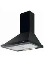
AD1006B - Range hood BRANDT - Free user manual and instructions
Find the device manual for free AD1006B BRANDT in PDF.


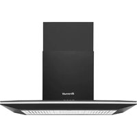
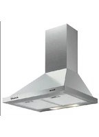
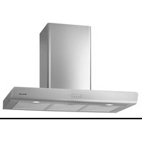
| Product Type | Range Hood |
| Brand | Brandt |
| Model | AD1006B |
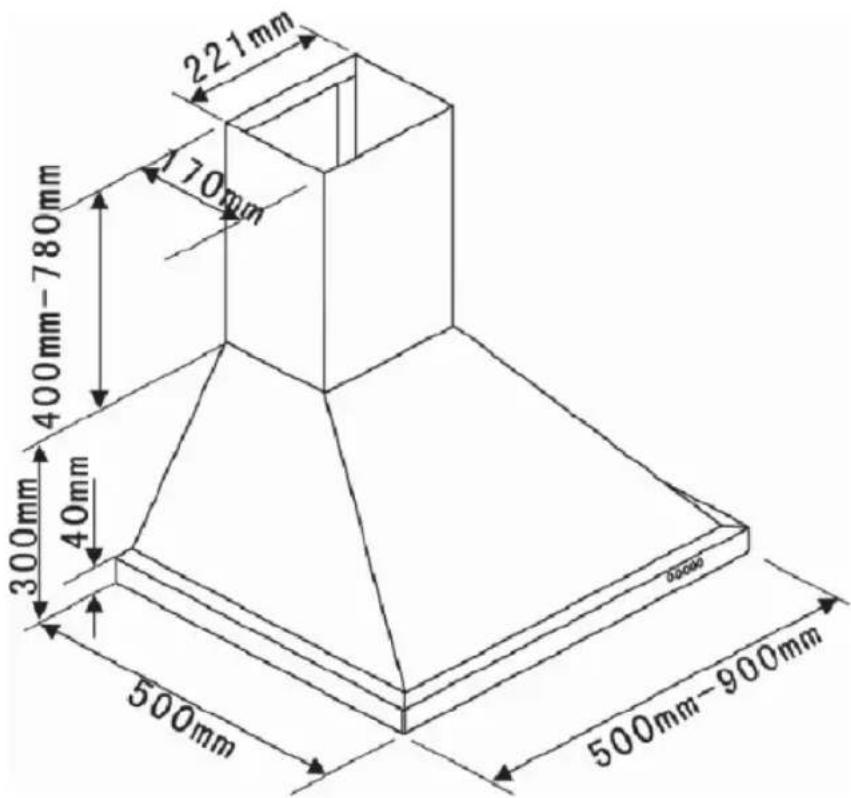
| Dimensions (W x D x H) | 500 mm x 500 mm x (400–780 mm) |
| Electrical Supply | 220–240 V, single phase, 10/16 A fuse |
| Power Cord | H05 VVF, 3×0.75 mm², with grounding |
| Maximum Airflow | 604.3 m³/h |
| Number of Fan Speeds | 3 (Low, Mid, High) + Stop |
| Lighting | LED, 2 W, average illumination 83 lux |
| Annual Energy Consumption | 55.9 kWh/annum |
| Energy Efficiency Index | 61.4 |
| Grease Filter Type | Metal mesh, dishwasher safe |
| Grease Filter Cleaning Frequency | Every 30 hours of use or monthly |
| Carbon Filter Replacement Frequency | Every 120 hours of use (optional) |
| Minimum Installation Height | 70 cm above electric/gas hob |
| Noise Level (Lowest Speed) | 62 dB(LwA) |
| Noise Level (Highest Speed) | 71 dB(LwA) |
| Modes | Evacuation (outdoor) and Recirculation (with carbon filter) |
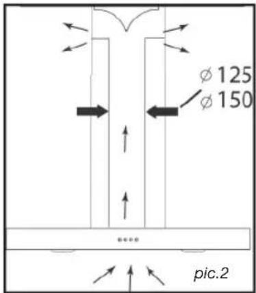
| Duct Diameter | 125 mm or 150 mm |
| Spare Parts Availability | Activated carbon filter, grease filters, bulb (via after-sales) |
| User-Replaceable Bulb | No; contact after-sales service |
Frequently Asked Questions - AD1006B BRANDT
User questions about AD1006B BRANDT
0 question about this device. Answer the ones you know or ask your own.
Ask a new question about this device
Download the instructions for your Range hood in PDF format for free! Find your manual AD1006B - BRANDT and take your electronic device back in hand. On this page are published all the documents necessary for the use of your device. AD1006B by BRANDT.
USER MANUAL AD1006B BRANDT
natural_image
Black-and-white photo of a person's face with earphones, next to a washing machine (no visible text or symbols)Brandt
| ES | 2 |
| EN | 25 |
| FR | 47 |
| PT | 69 |
| DE | 92 |
| IT | 115 |
| HU | 138 |
| SK | 160 |
| CZ | 182 |
| PL | 204 |
| DK | 227 |
| NL | 249 |
| SV | 272 |
| PYC | 294 |
natural_image
Technical line drawing of a brick chimney with a wall-mounted bracket and a side view showing a curved pipe or pipe connection (no text or symbols)
natural_image
Line drawing of a conical lamp with a cylindrical top and base, labeled 'foto 3' (no text or symbols on the diagram itself)natural_image
Line drawing of a conical lamp or lampshade with a cylindrical top and base, no text or symbols present.foto 3

natural_image
Simple line drawing of a refrigerator with ladder and labeled component C (no text or symbols beyond label)
natural_image
Architectural diagram of a chimney mounted on a brick wall, with directional arrows indicating airflow or movement (no text or symbols)
natural_image
Line drawing of a chimney with downward arrows indicating airflow or movement (no text or symbols)foto 5
natural_image
Simple line drawing of a cabinet or enclosure with labeled point C and caption 'foto 4' (no text or symbols on the diagram itself)
natural_image
Pure technical diagram of a mechanical component with no text or symbols
natural_image
Line drawing of a double-tube hood with ventilation ducts (no text or symbols)
natural_image
Architectural diagram of a chimney structure with brick wall and chimney, labeled 'foto 6' (no text or symbols on the diagram itself)
natural_image
Line drawing of a conical hood with two downward arrows indicating force or movement (no text or symbols)
Nota
4 / MANTENIMIENTO Y LIMPIEZA DEL APARATO ES

Atención
natural_image
Line drawing of a kitchen range hood with labeled components (no text or symbols)4 / MANTENIMIENTO Y LIMPIEZA DEL APARATOES
• LIMPIEZA DE LA SUPERFICIE EXTERIOR
As part of our commitment to constantly improving our products, we reserve the right to make changes to them based on technical advances to their technical and functional features and appearance.

Warning :
Before installing and using your appliance, please carefully read this Guide to Installation and Use, which will allow you to quickly familiarise yourself with its operation.
ENT
1 /NOTICES TO THE USER
- Safety recommendations 27
• Environmental protection 32
• Description of your appliance 33
2 / INSTALLING YOUR APPLIANCE
- Using the evacuation mode 34
- Using the recycling mode ____ 34
- Electrical connections 35
- Assembling the hood 36
- Assembling the ventilation shaft
° Outdoor evacuation 37
° Recycling 38
3 / USING YOUR APPLIANCE
• Description of control panel 39
4 / CARING FOR AND CLEANING YOUR APPLIANCE
- Cleaning the filter cartridges 40
- Changing the carbon filter 40
- Cleaning the outer surfaces 41
- Changing the light bulb 41
- Maintaining your appliance 42
5 / TROUBLESHOOTING 43
6 / AFTER-SALES SERVICE 44
EN 1 / NOTICES TO THE USER

Attention
Keep this user guide with your appliance. If the appliance is ever sold or transferred to another person, ensure that the new owner receives the user guide. Please become familiar with these recommendations before installing and using your appliance. They were written for your safety and the safety of others.
Safety and important precautions

These instructions are also available on the Brandt web site.
Please take heed of this advice when installing and using your appliance. These instructions are intended to protect your safety and the safety of others. Keep this manual with your appliance. If you sell or give the appliance to anyone else, make sure that you also give them this manual.
- In order to constantly improve our products, we reserve the right to make changes to their technical, functional or aesthetic characteristics in line with technological progress.
- Make a note of the references of your appliance on the "Consumer Service" page so that you can readily find them in future.
1 / NOTICES TO THE USER EN
Important precautions
- This appliance is designed for use by consumers in the home. Do not use it for commercial or industrial purposes or for any other purpose for which it is not intended.
- Unpack the appliance as soon as you receive it. Check its general appearance. Make a note of any reservations on the delivery slip and keep a copy.
- This appliance can be used by children aged under 8 and by persons with diminished physical, sensory or mental capacities, or persons without any experience or knowledge, provided that they are properly attended to or are given the instructions on how to use the appliance in complete safety and that any potential risks are anticipated. Children must not play with this appliance. The appliance must not be cleaned and maintained by unattended children.
- Caution: The accessible parts of this appliance may become hot when used with cooking equipment.
Electrical risks
- All the power supply circuits must be disconnected before touching the connection terminals. If the power cord is damaged, it must be
1 / NOTICES TO THE USEREN
replaced by the manufacturer, its after-sales service or a similarly qualified person in order to avoid any danger.
- The appliance can be disconnected by using an accessible power outlet or by incorporating a switch in the fixed lines, in accordance with the installation rules.
- Do not change or attempt to change the characteristics of this appliance. Doing so can be dangerous.
- The appliance must only be repaired by an approved specialist.
- Always disconnect the hood before cleaning or maintaining it.
- Never use steam or high-pressure tools to clean your appliance (for the purposes of electrical safety).
- The appliance can be disconnected by using an accessible power outlet or by incorporating a switch in the fixed lines, in accordance with the installation rules.
- Do not change or attempt to change the characteristics of this appliance. Doing so can be dangerous.
- The appliance must only be repaired by an approved specialist.
• Always disconnect the the hood before clean
1 / NOTICES TO THE USER EN
ing or maintaining it.
- Never use steam or high-pressure tools to clean your appliance (for the purposes of electrical safety).
Risk of asphyxiation
- The regulations applying to the evacuation of air must be obeyed. The air must not be sent into a duct used to evacuate fumes from appliances that use gas or other fuels (this does not apply to appliances that only emit air into the room).
- The room must be suitably ventilated when the range hood is used at the same time as appliances that use gas or other fuels (this does not apply to appliances that only emit air into the room).
Risk of fire
- It is forbidden to flambé food or to turn on gas rings that are not covered by a cooking recipient beneath the hood, as the flames may sucked in and damage the appliance.
- Keep a constant eye on fryers used beneath the hood. When heated to very high temperatures, oil and fat can catch fire.
- Clean the appliance and replace the filters at
1 / NOTICES TO THE USEREN
the recommended frequency. Accumulated deposits of grease can cause a fire.
- It is forbidden to use the hood above a fuel fire (wood, coal, etc.).
- If the hood is installed above a gas-fired appliance, leave at least 70 cm between the top of the range and the underside of the hood. If the instructions of the range installed under the hood specify a distance greater than 70 cm, then this distance must be respected.

Warning
In the case of a kitchen heated by a device connected to a chimney (a stove, for example) the "recycling" version of the hood should be installed. Do not use the hood without metal filters.
Suitable ventilation should be provided in the room when the hood is used at the same time as appliances operated by gas or another combustible fuel.
1 / NOTICES TO THE USER EN
• ENVIRONMENTAL PROTECTION
— This appliance's packaging material is recyclable. Help recycle it and protect the environment by dropping it off in the municipal receptacles provided for this purpose.
— Your appliance also contains a great amount of recyclable material. It is marked with this label to indicate the used appliances that should not be mixed with other waste. This way,

the appliance recycling organised by your manufacturer will be done under the best possible conditions, in compliance with European Directive 2002/96/EC on Waste Electrical and Electronic Equipment. Contact your town hall or your retailer for the used appliance collection points closest to your home.
— We thank you doing your part to protect the environment.

Warning
Installation should only be performed by installers and qualified technicians.

Warning
Remove the protective fi lm from the cartridge fi iter before use.
1 / NOTICES TO THE USEREN
• DESCRIPTION OF YOUR APPLIANCE
2 / INSTALLING YOUR APPLIANCE EN
— The appliance must be unplugged during installation or when any repairs or maintenance work is being performed.
— Ensure that the network voltage corresponds to the voltage noted on the identification plate located inside the hood.
— If the electrical installation at your residence requires any changes in order to hook up your Appliance, call upon a professional electrician.
— If the hood is being used in evacuation mode, do not connect the appliance to a combustion gas exhaust duct (boiler, chimney, etc.) or to a CMV (controlled mechanical ventilation) system.
— Under no circumstances should the exhaust duct empty into the attic.
— Install the hood at a safe distance of at least 70 cm from an electric, gas or combined cooking hob.
• USING THE EVACUATION MODE
If you possess an outlet to the exterior (pic. 1)
Your hood can be connected to this outlet using a fl ue (minimum diameter ∅ mm that is enamelled, in aluminium, fl exible or made of infl ammable material). If your fl ue is less than 125 mm in diameter, you must use the recycling mode.

• USING THE RECYCLING MODE
If you do not possess an outlet to the exterior (pic. 2)
All of our appliances can be used in recycling mode.
In this case, you should add an active carbon fi Iter which will keep in odours. (See Chapter 4: Changing the carbon fi Iter.)

Advice on how to save energy
To make optimal use of your appliance, keep the length of the duct and the number of bends in the duct to a strict minimum.
2 / INSTALLING YOUR APPLIANCEEN
• ELECTRICAL CONNECTIONS
During installation and maintenance operations, the appliance must be unplugged from the electrical grid; fuses must be cut off or removed.
The electrical connections are made before the appliance is installed in its housing.
Ensure that:
— the electrical installation has sufficient voltage,
— the electrical wires are in good condition,
— the diameter of the wires complies with the installation requirements.

Warning
This appliance is delivered with a H 05 VVF power cord that has three- 0.75mm2 conductors (neutral, phase and ground). It must be connected to the main power supply (which should be a 220-240 V single phase current) via a CEI 60083 standardised socket that should remain accessible after installation, in keeping with installation guidelines.
We cannot be held responsible for any accident resulting from an inexistent, defective or incorrect ground lead. The fuse for your installation must be 10 or 16A. If the power cable is damaged, call the after-sales service department in order to avoid danger.

Warning
If the electrical installation at your residence requires any changes in order to hook up your appliance, call upon a professional electrician.

Warning
If the hood displays any malfunctions, unplug the appliance or remove the fuse corresponding to the electrical socket where your appliance is plugged in.
2 / INSTALLING YOUR APPLIANCE EN
• ASSEMBLING THE HOOD

Warning
The hood must be installed in compliance with all applicable regulations concerning the ventilation of premises. In France these regulations are described in DTU 61.1 from the CSTB. In particular, the evacuated air should never be conveyed to a duct used to evacuate smoke from appliances that use gas or other combustible fuels. Unused ducts may only be used after approval from a competent specialist.
The minimum distance between the cooking surface and the lowest part of the hood must be 70 cm at least. If the instructions for the hob installed under the hood specify a distance of more than 70 cm, this requirement must be respected.
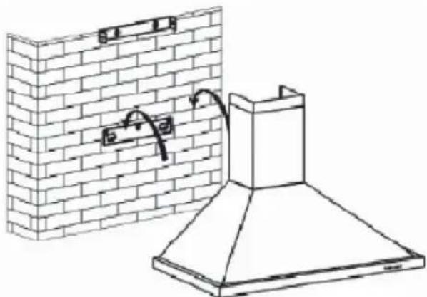
Fixing to the wall :
— Mark a vertical line on the wall centred on the cooktop.
— Mark on the wall the three holes that have to be drilled, using the supplied hood suspension hook and observing the recommended distance. (part A Pic. 1)
— Drill the three 8 mm diameter holes in a suitable position and insert the plugs.
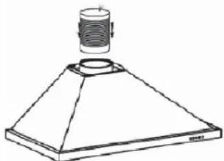
— Before fi xing the hood, mount the non-return valve on the motor outlet -Secure the hood's fi xing support, ensuring that it is perfectly level. (part A Pic. 1)
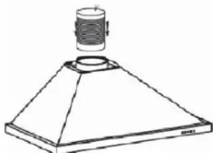
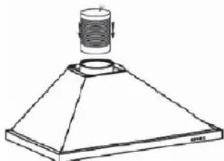
— Fix the extendable evacuation sleeve (not included) to the motor outlet without impeding the movement of the non-return valve.(Pic. 3)
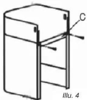
— Fit and secure the body of the hood on this support with the screws provided for this purpose. (Pic. 2)

natural_image
Technical line drawing of a brick chimney and its exterior wall assembly (no text or symbols)Pict 2
natural_image
Line drawing of a conical lamp with a cylindrical top and base, no text or symbols presentPict 3
2 / INSTALLING YOUR APPLIANCEEN
• ASSEMBLING THE VENTILATION SHAFT
• Outdoor evacuation
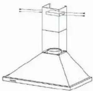
— Calculate the fi nal height for fixing the duct support U-bracket (part B Pic. 1)
— Mark the two holes accordingly
— Drill 8 mm diameter holes and secure the duct support bracket, ensuring that it is fixed on the same axis as the hood (part B Pic. 1)
— Fix the fl at bracket behind the lower duct.
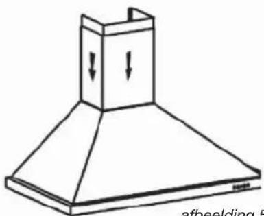
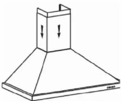
— Fix the two ducts to the hood.(Pic. 5)
— Connect the sleeve to the air outlet to the outside.
— Make the electrical connection to the hood using the mains supply cable.
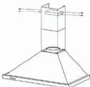
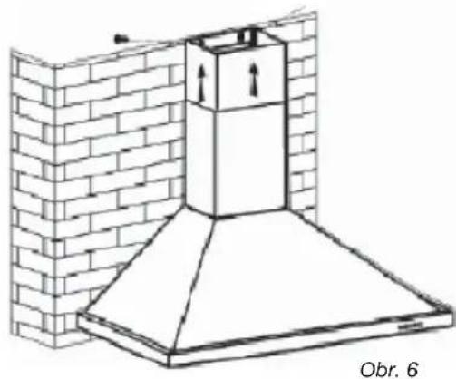
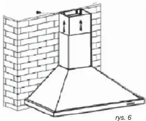
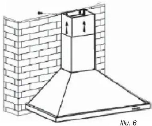
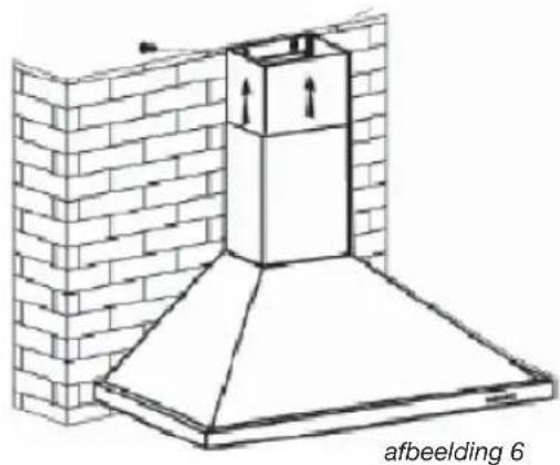
— Lift the upper duct up to the ceiling and fix it to the bracket using the screws.

natural_image
Architectural diagram of a chimney mounted on a brick wall, labeled 'Pict 6' (no text or symbols on the structure itself)
natural_image
Technical line drawing of a conical mechanical component with a cylindrical top and base (no text or symbols)Pict 3

natural_image
Line drawing of a chimney with downward arrows indicating airflow or pressure (no text or symbols)Pict 5

natural_image
Simple line drawing of a refrigerator with ladder and labeled part C, no text or symbols present2 / INSTALLING YOUR APPLIANCE EN
- Recycling
— Calculate the fi nal height for fixing the duct support U-bracket.
— Mark the two holes.
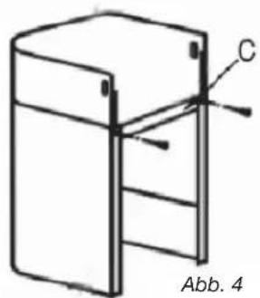
— Drill 8 mm diameter holes and secure the duct support bracket, ensuring that it is fixed in the same axis as the hood.
— Fix the fl at bracket behind the lower duct.
— Fit the sleeve adapter on the deflector (Pic. 8).
— Connect the extendable sleeve to the deflector.
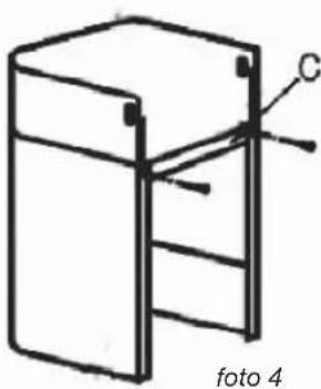
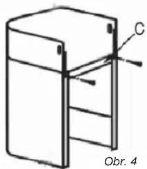
— Fit the two parts of the duct on to the hood (Pic. 5).
— Fit the defl ector (Pic. 8) into the upper duct by the ventilation inlets (Pic. 6)
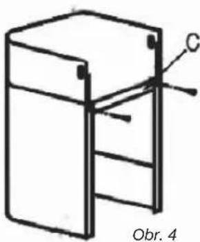
— Make the electrical connection to the hood using the mains supply cable.
— Lift the upper duct up to the ceiling and fix it to the bracket using the two screws.

natural_image
Simple line drawing of a 3D rectangular box with a labeled point C and caption 'Pict 4' (no text or symbols on the diagram itself)
natural_image
Pure technical diagram of a mechanical component with no text, numbers, or symbolsPict 8

natural_image
Line drawing of a double-bell tower with ventilation ducts (no text or symbols)
natural_image
Technical line drawing of a chimney structure mounted on a brick wall (no text or symbols)Pict 6

natural_image
Line drawing of a conical hood with downward arrows indicating compression or force (no text or symbols)
Tip
For optimal use of your appliance, we recommend that you connect the hood to a 150 mm-diameter fl ue (not delivered with the appliance). Minimise the number of angles and bends and the lengths of the fl ue. In the event that the hood will be operated using outdoor evacuation, you should ensure a sufficient inflow of fresh air to avoid a pressure deficiency in the room.

Warning
Do not use tools to remove the safety film of hood.
3 / USING YOUR APPLIANCEEN
• DESCRIPTION OF CONTROL PANEL
Push button
- Push stop button, and the motor will stop.
- Push the Low button, the motor runs at low speed.
- Push the Mid button, the motor runs at mid speed.
- Push the High button, the motor runs at high speed.
- Push the light button and the light will come on. Push it again and the light will turn off.

Stop
Low
Mid
High
Light

Advice on how to save energy
Adjust the speed to the cooking method and the number of pans in use. It is preferable to use the rings at the back of the range.
4 / CARING FOR AND CLEANING YOUR APPLIANCE EN

Warning
Always unplug the hood before cleaning it or performing other maintenance acts. Regular maintenance of your appliance is a guarantee of proper functioning, good performance and durability.

Warning
Failure to respect the guidelines for cleaning the appliance and fi liters may cause fi res. Please carefully adhere to the maintenance recommendations.
- CLEANING THE FILTER CARTRIDGES
They must be cleaned after approximately 30 hours of use or at least once a month. These fi Iters can be cleaned in a vertical position in your dishwasher.
Use a brush, hot water and mild detergent. Rinse and dry them thoroughly before returning them to the hood.
• Dismantling the fi Iter cartridge
— Turn the built-in fi Iter cartridge handle.
— Tilt the filter cartridge downward.

natural_image
Line drawing of a kitchen range hood with labeled components (no text or symbols)- CHANGING THE CARBON FILTER (optional)
Replace it after approximately 120 hours of use.
— Remove the fi Iter cartridge.
— Turn the carbon fi Iter to remove it.
— Do the operation in the reverse order to put a new filter back.
— Put the filter cartridges back.

EN 4 / CARING FOR AND CLEANING YOUR APPLIANCE
• CLEANING THE OUTER SURFACES
To clean the outside of your hood, use soapy water, but never use abrasive creams, corrosive detergents, scrubbing sponges or brushes. Wipe down with a soft, damp cloth.
• CHANGING THE LIGHT BULB
The lighting system cannot bereplaced by the user, contact Customer Service in case of malfunction.
4 / CARING FOR AND CLEANING YOUR APPLIANCE EN

Warning
Before carrying out any work, the power supply to the hood must be turned off, either by unplugging it or by using the circuit breaker switch.
• MAINTAINING YOUR APPLIANCE
| MAINTENANCE WHAT | TO DO | PRODUCTS/ACCESSORIES TO USE |
| Top surface and accessories | Never use metal scouring pads, abrasive products or excessively stiff brushes. | To clean the body and the lighting port, you should use only commercial household cleaning products diluted in water and then rinse using clean water, drying with a soft cloth. |
| Filter cartridge | This fi lter traps fatty vapours and dust. This component plays an important role in ensuring the effectiveness of your hood.In the event of tough stains, use a non-abrasive cream, then rinse with clean water. | Use a commercial household cleaning product then rinse abundantly and dry. These fi liters can be cleaned in a vertical position in your dishwasher.(Do not allow them to touch dirty dishes or silverware.) |
| Activated carbon fi lter | This fi lter traps odours and must be changed at least once a year depending on your level of use.You should order these fi liters from your dealer (quoting the reference shown on the identifi cation plate located inside the hood) and note the date the fi lter was changed. |
5 / TROUBLESHOOTINGEN
| SYMPTOMS | SOLUTIONS |
| The hood is not working... | Ensure that:• The power is not cut off.• A speed has been selected. |
| The hood is not operating effectively... | Ensure that:• The selected motor speed is suffi cient for the quantity of smoke and vapours to be cleared.• The kitchen is suffi ciently ventilated to allow for fresh air intake.• The carbon fi lter is not worn (hood operating in recycling mode). |
| The hood stopped working. | Ensure that:• The power is not cut off.• The single-pole cut-off device was not activated. |
6 / AFTER-SALES SERVICE EN
Any maintenance on your equipment should be undertaken by :
— either your dealer,
— or another qualified mechanic who is an authorized agent for the brand appliances.
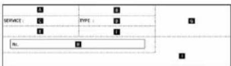
When making an appointment, state the full reference of your equipment (model, type and serial number). This information appears on the manufacturer's nameplate attached to your equipment.
Ecodesign information / Technical product ficheEN
This device complies with the delegated regulations (EU) 65/2014 and 66/2014 of the European Commission on the eco design requirements and energy labeling of household hoods.
symbol Value Unit
| Brand | Brandt | ||
| Model number | AD1006X / AD1006B /AD1006 WLMHT2060X/ LMHT2060B/ LMHT2060W | ||
| Annual energy consumption | AEC | 55,9 | kWh/annum |
| Energy efficiency index | EEi | 61,4 | - |
| Fluid dynamic efficiency index | FDE | 25,0 | - |
| Lighting efficiency index | LE | 41,5 | - |
| Grease filtering efficiency | GFE | 81.6 | - |
| Time increase factor | f | 1.1 | - |
| Maximum volumetric airflow of the cooker hood | Qmax | 604,3 | m3/h |
| Volumetric airflow at best efficiency point | QBEP | 364,3 | m3/h |
| Static pressure at the best efficiency point | PBEP | 335 | P |
| Power consumption at the best efficiency point | WBEP | 135,6 | W |
| Nominal power consumption of lighting system | WL | 2,0 | W |
| Average illumination of the lighting system | Emiddle | 83 | Lux/W |
| Power consumption in off mode | Po | 0.00 | W |
| Power consumption in standby mode | Ps | 0.00 | W |
| Volumetric airflow at the highest speed setting in normal use - | 628,3 | m3/h | |
| Volumetric airflow at the lowest speed setting in normal use - | 361,3 | m3/h | |
| Volumetric airflow in intensive or boost mode - | -- | m3/h | |
| Sound power emissions at the highest speed setting in normal use - | 71 | dB(LwA) | |
| Sound power emissions at the lowest speed setting in normal use - | 62 | dB(LwA) | |
| Sound power emissions in intensive / boost mode - | -- | dB(LwA) | |
symbol Value Unit
| Brand | Brandt | ||
| Model number | AD1009X | ||
| Annual energy consumption | AEC | 131.9 | kWh/annum |
| Energy efficiency index | EEi | 91.6 | - |
| Fluid dynamic efficiency index | FDE | 16.6 | - |
| Lighting efficiency index | LE | 1.6 | - |
| Grease filtering efficiency | GFE | 77.2 | - |
| Time increase factor | f | 1.4 | - |
| Maximum volumetric airflow of the cooker hood | Qmax | 618.8 | m3/h |
| Volumetric airflow at best efficiency point | QBEP | 336.0 | m3/h |
| Static pressure at the best efficiency point | PBEP | 317 | P |
| Power consumption at the best efficiency point | WBEP | 178.1 | W |
| Nominal power consumption of lighting system | WL | 56.0 | W |
| Average illumination of the lighting system | Emiddle | 89 | Lux/W |
| Power consumption in off mode | Po | 0.00 | W |
| Power consumption in standby mode | Ps | -- | W |
| Volumetric airflow at the highest speed setting in normal use - | 595.2 | m3/h | |
| Volumetric airflow at the lowest speed setting in normal use - | 372.0 | m3/h | |
| Volumetric airflow in intensive or boost mode - | -- | m3/h | |
| Sound power emissions at the highest speed setting in normal use - | 72 | dB(LwA) | |
| Sound power emissions at the lowest speed setting in normal use - | 67 | dB(LwA) | |
| Sound power emissions in intensive / boost mode - | -- | dB(LwA) | |
FR 47
natural_image
Technical line drawing of a brick chimney and chimney assembly (no text or symbols)Fig. 2
natural_image
Line drawing of a conical lamp with a cylindrical top and base (no text or symbols)Fig. 3
2 / INSTALLATION DE VOTRE APPAREILFR
• MONTAGE DE LA CHEMINEE
natural_image
Line drawing of a conical lamp with a cylindrical top and base, no text or symbols presentFig. 3

natural_image
Architectural diagram of a chimney mounted on a brick wall, labeled Fig. 6 (no text or symbols on the structure itself)
natural_image
Line drawing of a chimney with downward arrows indicating airflow or pressure (no text or symbols)Fig. 5

natural_image
Simple line drawing of a refrigerator with ladder and labeled component C, no text or symbols present2 / INSTALLATION DE VOTRE APPAREIL FR
- Recyclage
natural_image
Technical line drawing of a mechanical assembly with labeled component C, no readable text or symbols present
natural_image
Pure technical diagram of a mechanical component with no text, numbers, or symbolsFig. 8

natural_image
Line drawing of a double-bell tower with ventilation ducts (no text or symbols)
natural_image
Technical line drawing of a chimney structure mounted on a brick wall (no text or symbols)Fig. 6

natural_image
Line drawing of a conical hood with downward arrows indicating compression or force (no text or symbols)Fig. 5

Conseil
natural_image
Line drawing of a kitchen range hood with labeled components (no text or symbols)
FR 4 / ENTRETIEN ET NETTOYAGE DE VOTRE APPAREIL
• NETTOYAGE DE LA SURFACE EXTERIEURE
1- RELATIONS CONSOMMATEURS FRANCE
OU

natural_image
Technical line drawing of a brick chimney and wall assembly (no text or symbols)Fixação na parede:
natural_image
Technical line drawing of a conical lamp or fixture with a cylindrical top and base, labeled 'fig. 3' (no text or symbols on the diagram itself)natural_image
Technical line drawing of a chimney mounted on a brick wall, labeled 'fi g. 6' (no text or symbols on the diagram itself)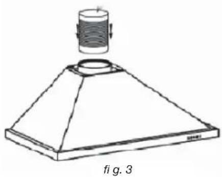
natural_image
Technical line drawing of a conical lamp or fixture with a cylindrical component above it, labeled 'fig. 3' (no text or symbols on the diagram itself)
natural_image
Line drawing of a conical exhaust hood with downward arrows indicating airflow or pressure, labeled 'fi g. 5' (no text or symbols on the diagram itself)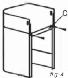
natural_image
Technical line drawing of a mechanical assembly with labeled component C, no readable text or symbols presentnatural_image
Pure technical diagram of a mechanical component with no text, numbers, or symbolsfig. 8
natural_image
Line drawing of a conical tower with vertical supports and a central circular opening (no text or symbols)
natural_image
Architectural diagram of a chimney mounted on a brick wall, showing airflow direction (no text or symbols)fig. 6

natural_image
Simple line drawing of a 3D rectangular box with a side panel and labeled point C, no text or symbols present.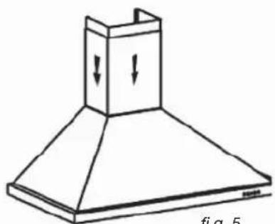
natural_image
Line drawing of a conical hood with downward arrows indicating force or movement (no text or symbols)
Conselho
natural_image
Line drawing of a kitchen range hood with labeled components (no text or symbols)natural_image
Technical line drawing of a brick wall and a chimney with mounting brackets (no text or symbols)Abb. 2

natural_image
Line drawing of a conical lamp with a cylindrical top and base (no text or symbols)Abb. 3
2 / ANSCHLIESSEN DES GERÄTSDE
• MONTAGE DER ROHRABDECKUNG
natural_image
Line drawing of a conical lampshade with a cylindrical top and base (no text or symbols)Abb. 3
natural_image
Technical line drawing of a mechanical assembly with labeled component C (no text or symbols beyond label)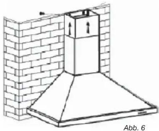
natural_image
Architectural diagram of a chimney mounted on a brick wall, labeled Abb. 6 (no text or symbols on the structure itself)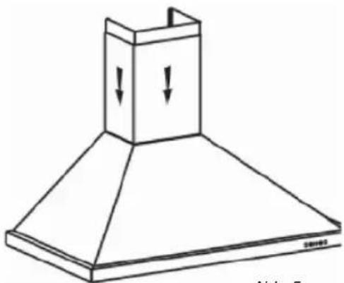
natural_image
Line drawing of a chimney with downward arrows indicating airflow or pressure (no text or symbols)Abb. 5
2 / ANSCHLIESSEN DES GERÄTS DE
• Umluft
natural_image
Simple line drawing of a 3D rectangular box with a labeled point C and label Abb. 4 (no text or symbols on the diagram itself)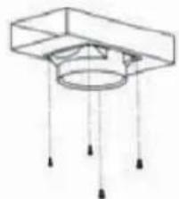
natural_image
Pure technical diagram of a mechanical component with no text, numbers, or symbolsAbb. 8

natural_image
Line drawing of a double-necked kitchen chimney with ventilation ducts (no text or symbols)
natural_image
Technical line drawing of a chimney structure mounted on a brick wall (no text or symbols)Abb. 6

natural_image
Line drawing of a chimney with downward arrows indicating airflow or force (no text or symbols)
Hinweis
natural_image
Line drawing of a kitchen range hood with labeled components (no text or symbols)• WECHSEL DES KOHLEFILTERS (optional)
natural_image
Technical line drawing of a brick chimney with a side panel and a separate 3D model labeled 'foto 2' (no text or symbols on the diagram itself)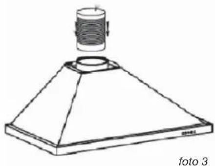
natural_image
Line drawing of a conical lamp with a cylindrical top and base, labeled 'foto 3' (no text or symbols on the diagram itself)2 / INSTALLAZIONE DEL DISPOSITIVOIT
• MONTAGGIO DELLA CANNA FUMARIA
natural_image
Line drawing of a conical lamp with a cylindrical top and base, no text or symbols presentfoto 3

natural_image
Simple line drawing of a refrigerator with ladder and labeled component C (no text or symbols beyond label)
natural_image
Architectural diagram of a chimney mounted on a brick wall, with directional arrows indicating airflow or movement (no text or symbols)
natural_image
Line drawing of a chimney with downward arrows indicating airflow or pressure (no text or symbols)foto 5
2 / INSTALLAZIONE DEL DISPOSITIVO IT
- Riciclaggio
natural_image
Pure technical diagram of a mechanical component with no text, numbers, or symbolsfoto 8

natural_image
Line drawing of a conical tower with vertical supports and a central opening (no text or symbols)
natural_image
Technical line drawing of a chimney mounted on a brick wall (no text or symbols)foto 6
natural_image
Simple line drawing of a cabinet or enclosure with labeled point C and caption 'foto 4' (no text or symbols on the diagram itself)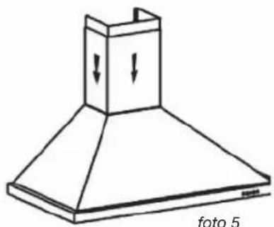
natural_image
Line drawing of a conical hood with downward arrows indicating force or movement (no text or symbols)
Nota
natural_image
Line drawing of a kitchen range hood with labeled components (no text or symbols)
4 / MANUTENZIONE E PULIZIA DEL DISPOSITIVOIT
• PULIZIA DELLA SUPERFICIE ESTERNA
natural_image
Technical line drawing of a brick chimney and its side profile, labeled '2. fotó' (no text or symbols on the diagram itself)
natural_image
Line drawing of a conical lamp with a cylindrical top and base, labeled '3. fotó' (no text or symbols on the diagram itself)HU 2 / A KÉSZÜLÉK ÜZEMBE HELYEZÉSE
natural_image
Line drawing of a conical lamp with a cylindrical top and base, no text or symbols present- fotó

natural_image
Technical line drawing of a chimney mounted on a brick wall, with no visible text or symbols.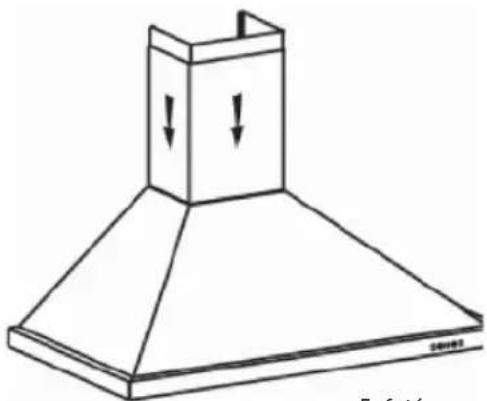
natural_image
Line drawing of a double-hop kitchen chimney with downward arrows indicating airflow or ventilation (no text or symbols)- fotó

2 / A KÉSZÜLÉK ÜZEMBE HELYEZÉSE
HU
• Keringetés
natural_image
Pure technical diagram of a mechanical component with no text, numbers, or symbols- fotó

natural_image
Line drawing of a double-bone kitchen chimney with ventilation ducts (no text or symbols)
natural_image
Technical line drawing of a chimney mounted on a brick wall (no text or symbols)- fotó

natural_image
Simple line drawing of a rectangular frame with a vertical support and labeled point C, no text or symbols present.
natural_image
Line drawing of a chimney with downward arrows indicating force or movement (no text or symbols)
Tudomásul
natural_image
Line drawing of a kitchen range hood with labeled components (no text or symbols)
natural_image
Technical line drawing of a brick wall and a chimney with mounting brackets (no text or symbols)Obr. 2

natural_image
Line drawing of a conical lamp or fixture with a cylindrical top and base (no text or symbols)Obr. 3
SK 2 / INŠTALÁCIA PRÍSTROJA
• MONTÁŽ KOMÍNA
• Vypúštanie von
natural_image
Technical line drawing of a conical mechanical component with a cylindrical top and base (no text or symbols)Obr. 3
natural_image
Technical line drawing of a chimney mounted on a brick wall, labeled 'Obr. 6' (no text or symbols on the diagram itself)
natural_image
Line drawing of a chimney with downward arrows indicating airflow or pressure (no text or symbols)Obr. 5
2 / INŠTALÁCIA PRÍSTROJA
SK
- Recyklácia
natural_image
Pure technical diagram of a mechanical component with no text, numbers, or symbolsObr. 8
natural_image
Line drawing of a double-bone kitchen chimney with ventilation ducts (no text or symbols)
natural_image
Technical line drawing of a chimney mounted on a brick wall (no text or symbols)Obr. 6

natural_image
Simple line drawing of a 3D rectangular frame with a vertical support and labeled point C, no text or symbols present.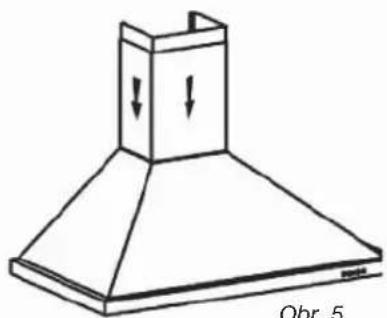
natural_image
Line drawing of a conical exhaust hood with downward arrows indicating airflow or pressure (no text or symbols)
Rada
Stop
Low
Mid
High
Light

Ako šetriť energiu
natural_image
Line drawing of a kitchen range hood with labeled components (no text or symbols)• VÝMENA UHLÍKOVÉHO FILTRA (možnost)
SK 4 / ÚDRŽBA A ČISTENIE PRÍSTROJA
• ČISTENIE VONKAJŠIEHO POVRCHU
2 / INSTALACE PŘÍSTROJE
2 / INSTALACE PŘÍSTROJE
CZ
CZ 2 / INSTALACE PŘÍSTROJE
• ELEKTRICKÉ ZAPOJENÍ
2 / INSTALACE PŘÍSTROJE
CZ
• MONTÁŽ EXTRAKČNÍHO ZVONU

Pozor
natural_image
Technical line drawing of a brick chimney and its side profile (no text or symbols)Obr. 2

natural_image
Line drawing of a conical lamp with a cylindrical top and base (no text or symbols)Obr. 3
CZ 2 / INSTALACE PŘÍSTROJE
• MONTÁŽ KOMÍNA
• Vypouštění ven
natural_image
Technical line drawing of a chimney mounted on a brick wall, labeled 'Obr. 6' (no other text or symbols)
natural_image
Technical line drawing of a conical lamp or fixture with a cylindrical component above it, labeled 'Obr. 3' (no other text or symbols)
natural_image
Line drawing of a conical exhaust hood with downward arrows indicating airflow or pressure, labeled 'Obr. 5' at bottom (no other text or symbols)
2 / INSTALACE PŘÍSTROJE
CZ
- Recyklování
natural_image
Pure technical diagram of a mechanical component with no text, numbers, or symbolsObr. 8
natural_image
Line drawing of a double-bell tower with ventilation ducts (no text or symbols)
natural_image
Architectural diagram of a chimney mounted on a brick wall, showing airflow direction (no text or symbols)Obr. 6
natural_image
Simple line drawing of a cabinet or enclosure with labeled point C and identifier Obr. 4 (no text or symbols on the diagram itself)
natural_image
Line drawing of a chimney with downward arrows indicating airflow or movement (no text or symbols)
Rada
natural_image
Line drawing of a kitchen range hood with labeled components (no text or symbols)
CZ 4 / ÚDRŽBA A ČIŠTĚNÍ PŘÍSTROJE
• ČIŠTĚNÍ VNĚJŠÍHO POVRCHU
• UŻYTKOWANIE W WERSJI WYCIĄGU
natural_image
Technical line drawing of a brick chimney and wall assembly (no text or symbols)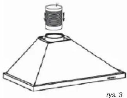
natural_image
Line drawing of a conical lamp with a cylindrical top and base, labeled 'rys. 3' (no text or symbols on the diagram itself)natural_image
Line drawing of a conical lamp with a cylindrical top and base, no text or symbols presentrys. 3
natural_image
Technical line drawing of a chimney mounted on a brick wall, labeled 'rys. 6' (no text or symbols on the diagram itself)
natural_image
Line drawing of a kitchen chimney with downward arrows indicating airflow or ventilation (no text or symbols)rys. 5

2 / INSTALACJA URZĄDZENIA
PL
- Tryb pochłaniacza
natural_image
Pure technical diagram of a mechanical component with no text, numbers, or symbolsrys. 8

natural_image
Line drawing of a double-tube hood with ventilation ducts (no text or symbols)
natural_image
Technical line drawing of a chimney mounted on a brick wall (no text or symbols)rys. 6

natural_image
Simple line drawing of a 3D rectangular box with a vertical support and labeled point C, no text or symbols present.
natural_image
Line drawing of a kitchen chimney with downward arrows indicating airflow or movement (no text or symbols)
Rada
4 / KONSERWACJA I CZYSZCZENIE URZĄDZENIA
PL

Uwaga
natural_image
Line drawing of a kitchen range hood with labeled components (no text or symbols)PL 4 / KONSERWACJA I CZYSZCZENIE URZĄDZENIA
• CZYSZCZENIE POWIERZCHNI ZEWNETRZNYCH
2 / INSTALLATION AF APPARATET
• BRUG MED RECIRKULERINGSVERSIONEN
installationskravene.

Advarsel
natural_image
Technical line drawing of a brick chimney and wall assembly (no text or symbols)
natural_image
Line drawing of a conical lamp with a cylindrical component above it, labeled 'Illu. 3' (no text or symbols on the diagram itself)2 / INSTALLATION AF APPARATET DK
• SAMLING AF VENTILATIONSSKAKTEN
natural_image
Line drawing of a conical lamp with a cylindrical top and base, no text or symbols presentIllu. 3
natural_image
Architectural diagram of a chimney mounted on a brick wall, showing structural details without any text or symbols.
natural_image
Line drawing of a chimney with downward arrows indicating airflow or pressure (no text or symbols)Illu. 5
natural_image
Simple line drawing of a refrigerator with ladder and labeled part C, no text or symbols present2 / INSTALLATION AF APPARATET DK
- Recirkulering
natural_image
Simple line drawing of a rectangular frame with a label 'C' and identifier 'Illu. 4' below (no text or symbols on the diagram itself)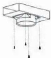
natural_image
Pure technical diagram of a mechanical component with no text, numbers, or symbolsIllu. 8

natural_image
Line drawing of a double-tube hood with ventilation ducts (no text or symbols)
natural_image
Technical line drawing of a chimney mounted on a brick wall (no text or symbols)Illu. 6

natural_image
Line drawing of a kitchen chimney with downward arrows indicating airflow or movement (no text or symbols)Illu. 5

Råd
4 / PLEJE OG RENG∅RING AF APPARATET DK

Advarsel
natural_image
Line drawing of a kitchen range hood with labeled components (no text or symbols)DK 4 / PLEJE OG RENG∅RING AF APPARATET
- RENG∅RING AF DE YDRE OVERFLADER
4 / PLEJE OG RENG∅RING AF APPARATET DK

Advarsel
2 / INSTALLATIE VAN HET APPARAATNL
natural_image
Technical line drawing of a brick chimney with a side panel and label 'afbeelding 2' (no other text or symbols)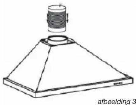
natural_image
Line drawing of a conical lamp or fixture with a cylindrical component above it, labeled 'afbeelding 3' at the bottom (no other text or symbols)2 / INSTALLATIE VAN HET APPARAATNL
• MONTAGE VAN HET AFVOERKANAAL
natural_image
Line drawing of a conical lampshade with a cylindrical top and base (no text or symbols)afbeelding 3
natural_image
Architectural diagram of a chimney mounted on a brick wall, labeled 'afbeelding 6' (no other text or symbols)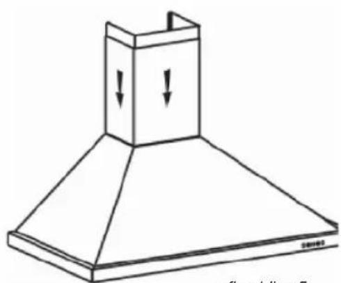
natural_image
Line drawing of a conical exhaust hood with downward arrows indicating airflow or pressure (no text or symbols)afbeelding 5

natural_image
Pure technical diagram of a mechanical component with no text, numbers, or symbolsafbeelding 8

natural_image
Line drawing of a conical tower with vertical supports and a central opening (no text or symbols)
natural_image
Technical line drawing of a chimney structure mounted on a brick wall (no text or symbols)afbeelding 6
natural_image
Line drawing of a chimney with downward arrows indicating airflow or movement (no text or symbols)afbeelding 5

Advies

natural_image
Line drawing of a kitchen range hood with labeled components (no text or symbols)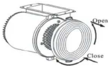
NL 4 / ONDERHOUD EN REINIGING VAN HET APPARAAT
• REINIGING VAN DE BUITENZIJDE
natural_image
Technical line drawing of a brick chimney and wall assembly (no text or symbols)fig. 2

natural_image
Line drawing of a conical lamp with a cylindrical top and base, no text or symbols presentfig. 3
2 / INSTALLATION AV APPARATENSV
• MONTERING AV SKORSTENEN
- Utvändigt utlopp
natural_image
Technical line drawing of a chimney mounted on a brick wall, labeled 'fi g. 6' (no text or symbols on the diagram itself)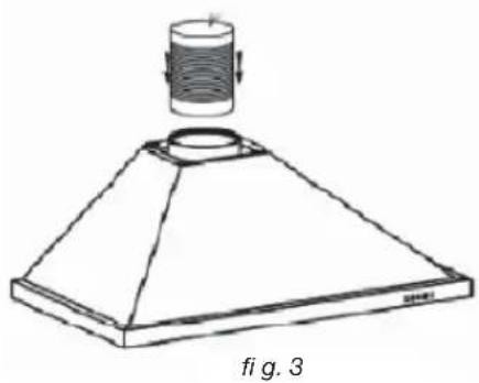
natural_image
Technical line drawing of a conical lamp or fixture with a cylindrical component and base plate (no text or symbols)
natural_image
Line drawing of a conical exhaust hood with downward arrows indicating airflow or pressure, labeled 'fi g. 5' at bottom (no text or symbols on the diagram itself)
natural_image
Simple line drawing of a cabinet or enclosure with labeled point C and figure number fig. 4 (no text or symbols on the diagram itself)2 / INSTALLATION AV APPARATEN SV
- Återcirkulation
natural_image
Pure technical diagram of a mechanical component with no text, numbers, or symbolsfig. 8

natural_image
Line drawing of a double-bell tower with ventilation ducts (no text or symbols)
natural_image
Technical line drawing of a chimney structure mounted on a brick wall (no text or symbols)fig. 6

natural_image
Simple line drawing of a 3D rectangular box with a side panel and labeled point C, no text or symbols present.
natural_image
Line drawing of a conical hood with downward arrows indicating compression or force (no text or symbols)fig. 5
Stop
Low
Mid
High
Light

Energisparråd
natural_image
Line drawing of a kitchen range hood with labeled components (no text or symbols)• UTBYTE AV KOLFILTRET (alternativt)
SV 4 / UNDERHÅLL OCH RENGÖRING AV APPARATEN
• RENGÖRING AV UTVÄNDIGA YTOR
natural_image
Technical line drawing of a brick chimney and its exterior wall assembly (no text or symbols)рис. 2
natural_image
Line drawing of a conical lamp with a cylindrical top and base, no text or symbols presentрис. 3
natural_image
Line drawing of a conical lamp with a cylindrical top and base, no text or symbols presentрис. 3

natural_image
Technical line drawing of a chimney mounted on a brick wall, showing structural details without any text or symbols.рис. 6
natural_image
Line drawing of a chimney with downward arrows indicating airflow or pressure (no text or symbols)рис. 5

natural_image
Technical line drawing of a mechanical component with labeled point C and caption 'рис. 4' (no text or symbols on the diagram itself)natural_image
Simple line drawing of a cabinet or enclosure with labeled point C and page number PNC. 4 (no text or symbols on the diagram itself)рис. 4

natural_image
Pure technical diagram of a mechanical component with no text, numbers, or symbolsрис. 8

natural_image
Line drawing of a double-bell tower with ventilation ducts (no text or symbols)
natural_image
Technical line drawing of a chimney structure mounted on a brick wall (no text or symbols)рис. 6

natural_image
Line drawing of a kitchen chimney with downward arrows indicating airflow or movement (no text or symbols)рис. 5

Совет

natural_image
Line drawing of a kitchen range hood with labeled components (no text or symbols)
- Nota
- / MANTENIMIENTO Y LIMPIEZA DEL APARATO ES
- Atención
- / MANTENIMIENTO Y LIMPIEZA DEL APARATOES
- • LIMPIEZA DE LA SUPERFICIE EXTERIOR
- Warning :
- ENT
- /NOTICES TO THE USER
- / INSTALLING YOUR APPLIANCE
- / USING YOUR APPLIANCE
- / CARING FOR AND CLEANING YOUR APPLIANCE
- / TROUBLESHOOTING 43
- / AFTER-SALES SERVICE 44
- EN 1 / NOTICES TO THE USER
- Attention
- Safety and important precautions
- / NOTICES TO THE USER EN
- Important precautions
- Electrical risks
- / NOTICES TO THE USEREN
- Risk of asphyxiation
- Risk of fire
- Warning
- • ENVIRONMENTAL PROTECTION
- / INSTALLING YOUR APPLIANCE EN
- • USING THE EVACUATION MODE
- • USING THE RECYCLING MODE
- Advice on how to save energy
- / INSTALLING YOUR APPLIANCEEN
- • ELECTRICAL CONNECTIONS
- Ensure that:
- • ASSEMBLING THE HOOD
- Fixing to the wall :
- • ASSEMBLING THE VENTILATION SHAFT
- • Outdoor evacuation
- - Recycling
- Tip
- / USING YOUR APPLIANCEEN
- • DESCRIPTION OF CONTROL PANEL
- Push button
- / CARING FOR AND CLEANING YOUR APPLIANCE EN
- - CLEANING THE FILTER CARTRIDGES
- • Dismantling the fi Iter cartridge
- - CHANGING THE CARBON FILTER (optional)
- EN 4 / CARING FOR AND CLEANING YOUR APPLIANCE
- • CLEANING THE OUTER SURFACES
- • CHANGING THE LIGHT BULB
- / AFTER-SALES SERVICE EN
- Ecodesign information / Technical product ficheEN
- / INSTALLATION DE VOTRE APPAREILFR
- • MONTAGE DE LA CHEMINEE
- / INSTALLATION DE VOTRE APPAREIL FR
- - Recyclage
- Conseil
- FR 4 / ENTRETIEN ET NETTOYAGE DE VOTRE APPAREIL
- • NETTOYAGE DE LA SURFACE EXTERIEURE
- 1- RELATIONS CONSOMMATEURS FRANCE
- Fixação na parede:
- Conselho
- / ANSCHLIESSEN DES GERÄTSDE
- • MONTAGE DER ROHRABDECKUNG
- / ANSCHLIESSEN DES GERÄTS DE
- • Umluft
- Hinweis
- • WECHSEL DES KOHLEFILTERS (optional)
- / INSTALLAZIONE DEL DISPOSITIVOIT
- • MONTAGGIO DELLA CANNA FUMARIA
- / INSTALLAZIONE DEL DISPOSITIVO IT
- - Riciclaggio
- / MANUTENZIONE E PULIZIA DEL DISPOSITIVOIT
- • PULIZIA DELLA SUPERFICIE ESTERNA
- HU 2 / A KÉSZÜLÉK ÜZEMBE HELYEZÉSE
- / A KÉSZÜLÉK ÜZEMBE HELYEZÉSE
- HU
- • Keringetés
- Tudomásul
- SK 2 / INŠTALÁCIA PRÍSTROJA
- • MONTÁŽ KOMÍNA
- • Vypúštanie von
- / INŠTALÁCIA PRÍSTROJA
- - Recyklácia
- Rada
- Ako šetriť energiu
- • VÝMENA UHLÍKOVÉHO FILTRA (možnost)
- SK 4 / ÚDRŽBA A ČISTENIE PRÍSTROJA
- • ČISTENIE VONKAJŠIEHO POVRCHU
- / INSTALACE PŘÍSTROJE
- CZ
- CZ 2 / INSTALACE PŘÍSTROJE
- • ELEKTRICKÉ ZAPOJENÍ
- • MONTÁŽ EXTRAKČNÍHO ZVONU
- Pozor
- • Vypouštění ven
- - Recyklování
- CZ 4 / ÚDRŽBA A ČIŠTĚNÍ PŘÍSTROJE
- • ČIŠTĚNÍ VNĚJŠÍHO POVRCHU
- • UŻYTKOWANIE W WERSJI WYCIĄGU
- / INSTALACJA URZĄDZENIA
- - Tryb pochłaniacza
- / KONSERWACJA I CZYSZCZENIE URZĄDZENIA
- Uwaga
- PL 4 / KONSERWACJA I CZYSZCZENIE URZĄDZENIA
- • CZYSZCZENIE POWIERZCHNI ZEWNETRZNYCH
- / INSTALLATION AF APPARATET
- • BRUG MED RECIRKULERINGSVERSIONEN
- Advarsel
- / INSTALLATION AF APPARATET DK
- • SAMLING AF VENTILATIONSSKAKTEN
- - Recirkulering
- Råd
- / PLEJE OG RENG∅RING AF APPARATET DK
- DK 4 / PLEJE OG RENG∅RING AF APPARATET
- - RENG∅RING AF DE YDRE OVERFLADER
- / INSTALLATIE VAN HET APPARAATNL
- • MONTAGE VAN HET AFVOERKANAAL
- Advies
- NL 4 / ONDERHOUD EN REINIGING VAN HET APPARAAT
- • REINIGING VAN DE BUITENZIJDE
- / INSTALLATION AV APPARATENSV
- • MONTERING AV SKORSTENEN
- - Utvändigt utlopp
- / INSTALLATION AV APPARATEN SV
- - Återcirkulation
- Energisparråd
- • UTBYTE AV KOLFILTRET (alternativt)
- SV 4 / UNDERHÅLL OCH RENGÖRING AV APPARATEN
- • RENGÖRING AV UTVÄNDIGA YTOR
- Совет
Brand : BRANDT
Model : AD1006B
Category : Range hood