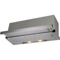
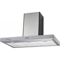
AT1460X - Range hood BRANDT - Free user manual and instructions
Find the device manual for free AT1460X BRANDT in PDF.


| Product Type | Range Hood (Canopy) |
| Brand | Brandt |
| Model | AT1460X |
| Dimensions (W x D x H) | 60 cm x 50 cm x 15 cm |
| Weight | Approx. 12 kg |
| Power Supply | 220-240 V, 50 Hz |
| Motor Power | 200 W |
| Number of Speeds | 3 |
| Lighting | 2 x 40 W halogen (or LED equivalent) |
| Airflow (max) | 600 m³/h |
| Noise Level | 55-65 dB (depending on speed) |
| Filter Type | Aluminum grease filter (washable) |
| Activated Carbon Filter | Optional for recirculation mode |
| Exhaust Diameter | 150 mm |
| Installation Type | Wall-mounted |
| Energy Class | B (typical) |
| Maintenance | Clean grease filter monthly; replace carbon filter every 6 months |
| Spare Parts | Grease filter, carbon filter, light bulbs |
| Safety Features | Thermal motor protection, auto shutoff timer (optional) |
| Warranty | 2 years (manufacturer warranty) |
Frequently Asked Questions - AT1460X BRANDT
User questions about AT1460X BRANDT
0 question about this device. Answer the ones you know or ask your own.
Ask a new question about this device
Download the instructions for your Range hood in PDF format for free! Find your manual AT1460X - BRANDT and take your electronic device back in hand. On this page are published all the documents necessary for the use of your device. AT1460X by BRANDT.
USER MANUAL AT1460X BRANDT
INSTRUCTIONS FOR INSTALLATION AND USE

To avoid the risk of accidents or damage to the appliance
it is essential to read these instruction before it is installed or used for the first time.
For original parts & reliable service:
Table of Contents
• From the Manufacturer 3
- Specifications 3
• SAFETY : Read this first ! 4
• Description of Parts 5, 6
• Instruction for use 6
• Technical Information 7
• Installation 8
• Cleaning & Maintenance 9, 10
- Troubleshooting 11
Troubleshooting
| Symptoms | Possible Cause | Action |
| Does not function | No electrical supply | Check that the plug is connected. |
| Check that the main switch is turned on. | ||
| Poor airflow | Aluminum filters grease clogged | Clean the filters and replace when it is dry |
| Charcoal grease filters clogged | Replace charcoal filters with new sets | |
| Motor running but no airflow | Butterfly valve jammed | Contact technician |
| Motor cuts after a few minutes | High temperature safety device activated | The kitchen is not sufficiently ventilated |
| The hood is installed too near the cooking stove | The hood must be at least 65cm from stove | |
| Strong cooking smell | Charcoal filters not installed | In re-circulating mode, charcoal filters must be installed |
| Oil dripping onto stove | Aluminum grease filter saturated | Wash the aluminum grease filters |
| Aluminum grease filter saturated | Wash the aluminum grease filters | |
| Whirring sound | Foreign object in contact with fan blade | Contact technician |
Cleaning & Maintenance (continued)
Activated charcoal filter
To install the charcoal filter, the motor anchorage is made to coincide with the anchor points of the activated charcoal filter and turn in clockwise.
The carbon filter lasts from three to six months depending on the particular conditions of use.
The activated carbon filter can neither be exhausted, it must be changed.
Changing Bulbs
Remove the filter support to access the bulbs.
Take care to disconnect the mains beforehand and that the bulbs to be replaces are not hot.
The maximum bulbs power is 40W.
From the Manufacturer
- This appliance and it's packaging are produced by processes that minimize waste and respect the environment.
- Please help us to continue the protection of the environment by disposing of the packaging in a correct manner.
- Safety!
- Please do not allow young children to play with the plastic bag packaging.
- Before disposing of any old appliances, be sure to cut off the power chord so that others will not be endangered by a defective electric appliance.
Specifications
| Input | 220-240V 50. Hz |
| Power | 155W |
| Lamps | 2X40W |
External Dimensions
| 60cm version | : | 600x280x180mm |
| 90cm version | : | 900x280x180mm |
| Air flow | : | 440m3/hr |
SAFETY : Read this First !
- Do not connect the appliance if there are obvious signs of transportation damage.
- Read this user manual thoroughly before attempting to use this appliance.
• Installation and repair should be attempted only by qualified technical personnel.
• It is dangerous to modify any part of this appliance. - The manufacturer declines all responsibility in case of failure to adopt proper safety measures.
- Ensure the location in which this appliance is installed has good, permanent ventilation.
- The cooker hoods should be placed at a distance of 65-75cm from the cooking surface for best effect. **if the cooktop is gas, 65 - 75cm is calculated from the top of the pot stand.
• Use an electrical connector with earth that is correct for your location. - Check that the voltage in your area is correct before plugging in.
- Multiple plugs and extension cables must not be used. Overload is dangerous and may cause a fire.
- Ensure that the power supply chord is free from any heat source or sharp objects.
- The appliance should be switched off and the electrical supply disconnected before any cleaning or maintenance work can be carried out.
- This appliance is not intended for use by persons (including children) with reduced physical, sensory or mental capabilities, or lack of experience and knowledge, unless they have been given supervision or instruction concerning use of the appliance by a person responsible for their safety.
Children should be supervised to ensure that they do not play with the appliance.
- If the supply cord is damaged, it must be replaced by the manufacturer, its service agent or similarly qualified persons in order to avoid a hazard.
Clause 7 (60335-2-31)
There is a fire risk if cleaning is not carried out in according with the instructions.
The hood use four hob element at most.
Cleaning & Maintenance
Before carrying out any cleaning or maintenance activities, ensure that the appliances is disconnected from the mains.
To carry out cleaning and maintenance, follow the safety Instructions.
Filter Cleaning
To withdraw the filters from their locations release the anchoring points. Clean the filter either putting in the dishwasher (refer to notes) or leaving it standing in hot water to simplify the removal of grease or, if wished, by means of special sprays (protecting the non metallic parts). Once clean, leave it to dry. Notes: cleaning in the dishwasher with aggressive detergents may blacken the surface of metallic parts, without this affecting its gas retaining properties. The filter must be cleaned at least once a month depending on how often the appliances is used. It must be remembered that grease is deposited in the extractor when cooking, whether it is switched on or not.
** before using, please take note to remove the plastic wrapping and fix back the circular charcoal filter after the wrapper has been removed.
Cleaning the appliances body
The use of (40°C approx.) soapy water is recommended. A cloth moistened in this water is used for cleaning the extractor, paying special attention to the grids. Afterwards, dry it using a lint-free cloth.
Note: Never use metallic scouring pads or abrasive products that could damage the surface. Do not use scrapers with metallic surfaces such as knives, scissors etc.
Installation
To fix the extractor to the kitchen unit.
The lower part of the extractor must be located at a minimum height of 65cm above the hob for electric cookers and 65cm for gas cookers. If the instructions of a gas cooker indicate a greater distance these must be observed.
When the extractor is working at the same time as other non-electrical cooking equipment, the outlet air pressure must not exceed 4 Pa.
To achieve optimum performance the length of the outlet hose should not exceed 2 meters, or include more than two 90 angles (elbows)
Although venting to the outside is recommended, activated carbon filters may be used, which allow the gas to be returned to the kitchen through the outlet pipe.

Description of Parts
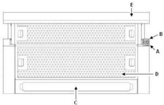
A Motor controls that allow two positions to be selected.
B Light switch independent of the motors.
C Lighting by means of lamps.
D Filters located over cooking area, easily withdrawn for cleaning.
E Extractable group that allows a greater gas capture area.
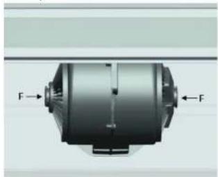
F Possibility of incorporating activated charcoal filter.
G-H Anti return tabs to be located in the outlet mouth, locating ends in the holes provided.
natural_image
Mechanical component diagram showing a cylindrical shaft with force vectors labeled F (no text or symbols beyond labels)
Instructions for use
By pressing the button shown in the below, you will be able to control the functions of the extractor.
To achieve better extraction, we recommend switching on the extractor a few minutes before starting to cook (3—5 minutes) so that the air flow is continuous and stable when extracting fumes.
Likewise, keep the extractor switched on for a few minutes when cooking is complete to allow all fumes and odors to be expelled.

natural_image
Architectural line drawing of a building facade with windows and doorways (no text or symbols)| Speed | |
| I | Low |
| II | High |
| Light ON | |
| 0 | OFF |
| A | Automatic |
Technical Information
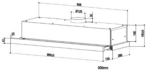
Dimensions
Width = 600 - 900 mm
Depth = 280 mm
Height = 180 mm

- Table of Contents
- Troubleshooting
- Cleaning & Maintenance (continued)
- Activated charcoal filter
- Changing Bulbs
- From the Manufacturer
- - Safety!
- SAFETY : Read this First !
- Clause 7 (60335-2-31)
- Cleaning & Maintenance
- Filter Cleaning
- Cleaning the appliances body
- Installation
- Description of Parts
- Instructions for use
- Technical Information
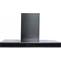
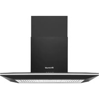
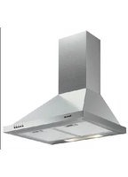
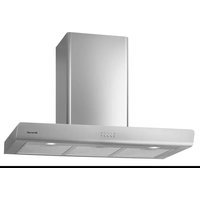
Brand : BRANDT
Model : AT1460X
Category : Range hood