
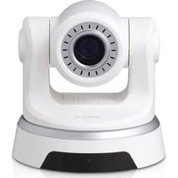
DCS-6004L - Surveillance Camera D-LINK - Free user manual and instructions
Find the device manual for free DCS-6004L D-LINK in PDF.


| Product Type | HD PoE Mini Dome Network Camera |
| Model | DCS-6004L |
| Brand | D-Link |
| Resolution | HD (720p) |
| Connectivity | 10/100 Ethernet (PoE supported) |
| Power Supply | Power over Ethernet (PoE) or DC 5V (adapter included) |
| Mounting Type | Wall or ceiling mount with included bracket |
| Viewing Angle | Adjustable (pan/tilt via manual adjustment) |
| Remote Access | Via mydlink cloud service |
| System Requirements | Windows 8/7/Vista/XP or Mac OS X 10.6+, 1.3 GHz CPU, 128 MB RAM, Java, Internet Explorer 7+, Firefox 12+, Safari 4+, Chrome 20+ |
| Network Standard | IEEE 802.3, 802.3u |
| Dimensions (Approx.) | 100 mm (diameter) x 60 mm (height) |
| Weight (Approx.) | 200 g |
| Operating Temperature | 0°C to 40°C (32°F to 104°F) |
| LED Indicators | Power, WPS (if applicable) |
| Included Accessories | Power adapter, network cable, Ethernet cable, installation CD, audio extension cable, female Ethernet extension adapter, mounting screws, alignment sticker |
| Security | Password-protected access, encryption via HTTPS (when configured) |
| Maintenance | Clean lens with soft dry cloth; avoid liquids |
| Repairability | Not user-serviceable; contact D-Link support |
Frequently Asked Questions - DCS-6004L D-LINK
User questions about DCS-6004L D-LINK
0 question about this device. Answer the ones you know or ask your own.
Ask a new question about this device
Download the instructions for your Surveillance Camera in PDF format for free! Find your manual DCS-6004L - D-LINK and take your electronic device back in hand. On this page are published all the documents necessary for the use of your device. DCS-6004L by D-LINK.
USER MANUAL DCS-6004L D-LINK
flowchart
graph TD
    A["D-Link"] --> B["Step 1: Box with antenna, cable strap, camera, and USB cable"]
    B --> C["Step 2: Box with cable strap, cable strap, camera, and USB cable"]
    C --> D["Step 3: Box with cable strap, cable strap, camera, and USB cable"]
    D --> E["End"]
DCS-6004L HD POE MINI DOME NETWORK CAMERA OR DCS-6005L HD WIRELESS MINI DOME NETWORK CAMERA
POWER ADAPTER
NETWORK CABLE ETHERNET CABLE (CAT5 UTP)
INSTALLATION CD INCLUDES SETUP WIZARD, TECHNICAL MANUALS
AUDIO EXTENSION CABLE
FEMALE ETHERNET EXTENSION ADAPTER
If any of these items are missing from your packaging, contact your reseller.
PRODUCT SETUP SYSTEM REQUIREMENTS
• A router (a D-Link Cloud Router is recommended)
• A broadband Internet connection
- An e-mail account (required to register for mydlink service)
- Computer with:
- Microsoft Windows® 8/7/Vista/XP, or Mac with OS X 10.6 or higher
• PC with 1.3 GHz or above and at least 128 MB RAM - Internet Explorer 7, Firefox 12, Safari 4, or Chrome 20 or higher version with Java installed and enabled
- Existing 10/100 Ethernet-based network or 802.11g/n wireless network
If you have a D-Link Cloud Router, you can take advantage of Zero Configuration Setup. This feature automatically configures your camera's settings for you and adds it to your mydlink account automatically. If you do not have a D-Link Cloud Router, you can use the Setup Wizard to install and configure your camera, as described in the following section.

natural_image
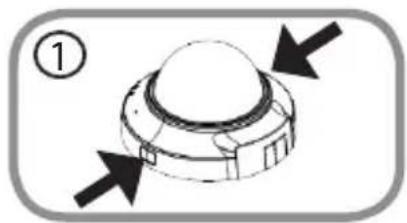
Diagram of a mechanical component with two black arrows pointing outward (no text or symbols)Step 1:
Remove the camera housing by squeezing the housing release buttons on both sides of the came

natural_image
Illustration of a robotic arm with a blue tool inserted, showing no text or symbolsStep 2:
Connect the included Ethernet cable to the network cable connector located inside of the camera and attach it to the network.

natural_image
Mechanical assembly diagram showing a motor or gear mechanism with orange and blue arrows indicating direction (no text or symbols present)Step 3:
If you are going to power the device using Power over Ethernet, you can skip this step and continue with the configuration of the device. Otherwise, attach the external power supply to the DC power input connector located on the inside of the camera and connect it to your wall outlet or power strip. Power is confirmed when the green LED Power Indicator is lit.

natural_image
Diagram of a mechanical component with downward arrows indicating force or direction (no text or symbols)Step 4:
Reattach the camera housing by lining up the housing so that the access port on the housing matches the access port on the camera base. Firmly push down until the camera housing snaps back onto the camera base.
USING THE INSTALLATION WIZARD
If you do not have a D-Link Cloud Router, you can simply use any Windows or Mac computer to go through the Installation Wizard from the CD, which will guide you through the installation process from connecting your hardware to configuring your camera.
If you do not have a CD-ROM drive, or the CD is missing, please download the Setup Wizard from http://www.mydlink.com/support
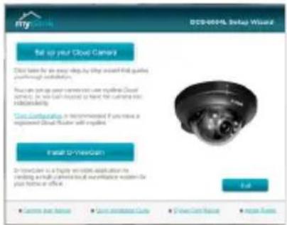
- Windows Users: Insert the CD. Simply click Set up your Cloud Camera to go through the Setup Wizard. If the Setup Wizard program does not automatically start on your computer, go to Start > Run. In the run box type D:\autorun.exe (where D: represents the drive letter of your CD-ROM drive) and click OK.
- Mac Users: Insert the CD. On the desktop, open your CD drive, double-click on the SetupWizard file, wait about 20-30 seconds, and follow the instructions.
GETTING STARTED WITH mydlink
mydlink is a web-based service which allows you to view and control your mydlink-enabled devices through any computer connected to the Internet. If you have cameras linked to your mydlink account, you will be able to see their live views using the mydlink website. Follow the instructions below to access your mydlink account.
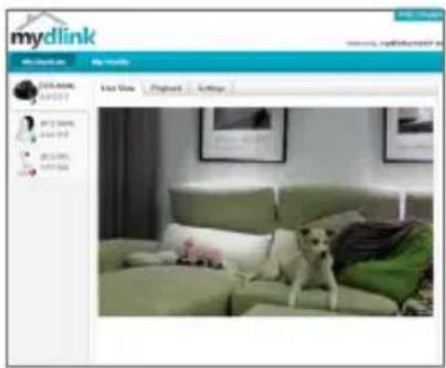
- Open a web browser on any computer connected to the Internet.
- Type http://www.mydlink.com in the address bar and press Enter.
• Sign in using your mydlink account. -
From the home screen, you will be able to view all devices which have been linked to your mydlink account.
-
Ensure that your browser supports both Java and ActiveX, and that these features have been installed and enabled.
- Windows does not have Java installed by default. You can download the latest version from http://www.java.com
- In Mac OS X 10.7.x, Java applets are disabled by default. To enable Java applets, click the Finder > Applications > Utilities > Java Preferences and check the Enable applet plug-in and Web Start applications option.
- The ActiveX® controls in IE will install automatically if needed. We suggest that you make sure that you have enabled the related options in Tools > Internet Options > Security > Custom Level.
MOUNTING THE CAMERA
Please refer to the steps below to assist you with mounting the camera. We suggest that you configure the camera before mounting.

natural_image
Technical diagram of a mechanical component with a circular housing and bolted elements, labeled with number 1 (no text or symbols on the diagram itself)Step 1:
The camera needs to be separated from the mounting base to expose the holes in the mounting base. Remove the camera head from the mounting base by firmly holding the camera with the D-Link logo facing you and then sliding the mounting base towards you.

Step 2:
Place the mounting base alignment sticker where you want to position the camera. Depending on the material of the wall or ceiling, use proper tools to drill two holes where you placed the alignment sticker. If the wall is made out of concrete, drill the holes first, then insert the plastic anchors to support the screws.

Step 3:
Place the mounting base over the holes that are in the wall. Make sure to align the mounting base holes with the holes in the wall. Use the supplied screws to attach the mounting base to the surface of the wall.
Step 4:
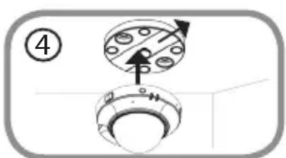
With the D-Link logo facing you, reattach the camera to the mounting plate by sliding the camera towards you until it locks into position.
natural_image
Simple line drawing of a mechanical component with no text or symbolsStep 5:
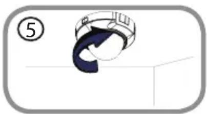
Adjust the direction of the camera as desired by rotating it.
ADJUSTING VIEWING ANGLE
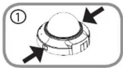
natural_image
Diagram of a mechanical component with directional arrows indicating movement or force (no text or symbols)Step 1:
The camera housing needs to be separated from the camera base to expose the screw used to adjust the viewing angle. Remove the camera housing from the camera base by squeezing the housing release buttons on either side of the camera.

natural_image
Diagram of a mechanical component with upward arrows and a circular symbol (no text or labels)Step 2:
Lift the camera housing up off the camera base once the housing has been released.
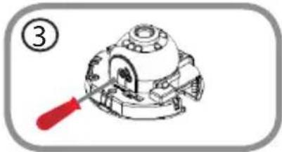
natural_image
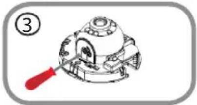
Technical line drawing of a mechanical component with a red screwdriver, no visible text or symbolsStep 3:
Use a philips head screwdriver to loosen the retaining screw used to secure the viewing angle of the camera lens.
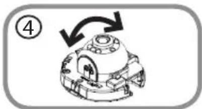
natural_image
Mechanical component diagram with directional arrows indicating motion (no text or symbols)Step 4:
Manually adjust the viewing angle back and forth to your desired location.
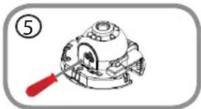
natural_image
Technical illustration of a mechanical component with a red-handled tool, no visible text or symbolsStep 5:
Use a philips head screwdriver to tighten the retaining screw used to secure the viewing angle of the camera lens.

natural_image
Technical diagram of a mechanical component with directional arrows, no readable text or symbolsStep 6:
Reattach the camera housing by lining up the housing so that the access port on the housing matches the access port on the camera base. Firmly push down until the camera housing snaps back onto the camera base.
TROUBLESHOOTING
SETUP AND CONFIGURATION PROBLEMS
1. HOW DO I CONNECT MY CAMERA USING WPS? (DCS-6005L ONLY)
We recommend that you use either the Zero Configuration or Setup Wizard method described earlier in this guide as they will automatically configure your camera for your wireless network.
If you wish to use WPS to connect your camera, follow these steps:
- Press and hold the WPS button on the back of the camera for 5 seconds. The blue WPS status LED will blink.
- Press the WPS button on your wireless router or access point within 60 seconds. On some routers, you may need to log into the web interface and then click an onscreen button to activate the WPS feature. If you are not sure where the WPS button is on your router or access point, please refer to your router's user manual.
You can find software updates and user documentation on the D-Link website.
Tech Support for customers in
Australia:
Tel: 1300-766-868
24/7 Technical Support
Web: http://www.dlink.com.au
E-mail: support@dlink.com.au
India:
Tel: +91-22-27626600
Toll Free 1800-22-8998
Web: www.dlink.co.in
E-Mail: helpdesk@dlink.co.in
Singapore, Thailand, Indonesia, Malaysia, Philippines, Vietnam:
Singapore - www.dlink.com.sg
Philippines - www.dlink.com.ph
Vietnam - www.dlink.com.vn
Korea:
Tel : +82-2-2028-1810
Monday to Friday 9:00am to 6:00pm
24/7 Technical Support
Web: http://www.dlink.co.nz
E-mail: support@dlink.co.nz
South Africa and Sub Sahara Region:
Tel: +27 12 661 2025
08600 DLINK (for South Africa only)
Monday to Friday 8:30am to 9:00pm South
Africa Time
Web: http://www.d-link.co.za
E-mail: support@d-link.co.za
Saudi Arabia (KSA):
Tel: +966 01 217 0008
Fax: +966 01 217 0009
Saturday to Wednesday 9.30AM to 6.30PM
Thursdays 9.30AM to 2.00 PM
E-mail: Support.sa@dlink-me.com
D-Link Middle East - Dubai, U.A.E.
Plot No. S31102,
Jebel Ali Free Zone South,
P.O.Box 18224, Dubai, U.A.E.
Tel: +971-4-8809022
Fax: +971-4-8809066 / 8809069
Technical Support: +971-4-8809033
General Inquiries: info.me@dlink-me.com
Tech Support: support.me@dlink-me.com
Egypt
1, Makram Ebeid Street - City Lights Building
Nasrcity - Cairo, Egypt
Floor 6, office C2
Tel.: +2 02 26718375 - +2 02 26717280
Technical Support: +2 02 26738470
General Inquiries: info.eg@dlink-me.com
Tech Support: support.eg@dlink-me.com
Kingdom of Saudi Arabia
Office # 84,
Al Khaleej Building ( Mujamathu Al-Khaleej)
Opp. King Fahd Road, Olaya
Riyadh - Saudi Arabia
Tel: +966 1 217 0008
Technical Support:
+966 1 2170009 / +966 2 6522951
General Inquiries: info.sa@dlink-me.com
Tech Support: support.sa@dlink-me.com
Pakistan
Islamabad Office:
61-A, Jinnah Avenue, Blue Area,
Suite # 11, EBC, Saudi Pak Tower,
Islamabad - Pakistan
Tel.: +92-51-2800397, 2800398
Fax: +92-51-2800399
Karachi Office:
D-147/1, KDA Scheme # 1,
Opposite Mudassir Park, Karsaz Road,
Karachi – Pakistan
Phone: +92-21-34548158, 34326649
Fax: +92-21-4375727
Technical Support: +92-21-34548310, 34305069
General Inquiries: info.pk@dlink-me.com
Tech Support: support.pk@dlink-me.com
Iran
Unit 5, 5th Floor, No. 20, 17th Alley, Bokharest
St., Argentine Sq.,
Tehran IRAN
Postal Code : 1513833817
Tel: +98-21-88880918,19
+98-21-88706653,54
General Inquiries: info.ir@dlink-me.com
Tech Support: support.ir@dlink-me.com
Morocco
M.I.T.C
Web:www.dlink.com.tr
Teknik Destek: support.tr@dlink.com.tr
ISRAEL
בְרָהוֹרִי
20
49348 n"ɔ, 170n n"ɔ
7060.τ.π
073-796-2797:11970
natural_image
Diagram of a mechanical component with two opposing arrows indicating direction (no text or symbols)War 1:
natural_image
Illustration of a robotic arm with a blue tool inserted, no text or symbols presentWar 2:
natural_image
Mechanical assembly diagram showing a motor or gear mechanism with orange and blue arrows indicating direction (no text or symbols present)War 3:
natural_image
Diagram of a mechanical component with downward arrows indicating force or direction (no text or symbols)War 4:
natural_image
Technical diagram of a mechanical component with a circular housing and central hub, marked with an arrow (no text or symbols present)War 1:
War 2:
natural_image
Simple diagram showing a circular object with internal patterns and two vertical arrows pointing downward, enclosed in a rounded rectangle (no text or symbols)War 3:
natural_image
Simple line drawing of a mechanical component with a numbered label (5) and no text or symbolsWar 5:
natural_image
Diagram of a mechanical component with directional arrows indicating movement or force (no text or symbols)War 1:
natural_image
Diagram of a spacecraft with directional arrows indicating orientation (no text or labels)War 2:
natural_image
Technical line drawing of a mechanical component with a red screwdriver, no text or symbols presentWar 3:
natural_image
Mechanical component diagram showing a rotating assembly with arrows indicating motion (no text or symbols)War 4:
natural_image
Technical line drawing of a mechanical component with a red-handled tool, no visible text or symbolsWar 5:
natural_image
Diagram of a mechanical component with arrows indicating downward motion, no text or symbols presentWar 6:
natural_image
Diagram of a mechanical component with two black arrows pointing outward (no text or symbols)Paso 1:
natural_image
Illustration of a robotic arm with a blue tool inserted, showing no text or symbolsPaso 2:
natural_image
Mechanical assembly diagram showing a motor or gear component with directional arrows indicating motion (no text or symbols present)Paso 3:
natural_image
Diagram of a mechanical component with downward arrows indicating force or direction (no text or symbols)Paso 4:
natural_image
Diagram of a mechanical component with a circular housing and central hub, marked with an arrow (no text or symbols present)Paso 1:
natural_image
Simple 3D diagram of a mechanical component with a curved arrow and circular head, no text or symbols present.Paso 5:
natural_image
Diagram of a mechanical component with directional arrows indicating movement or force (no text or symbols)Paso 1:
natural_image
Diagram of a mechanical component with upward arrows and a circular symbol (no text or labels)Paso 2:
natural_image
Technical line drawing of a mechanical component with a red screwdriver, no text or symbols presentPaso 3:
natural_image
Mechanical component diagram with directional arrows indicating motion (no text or symbols)Paso 4:
natural_image
Technical line drawing of a mechanical component with a red-handled handle (no text or symbols)Paso 5:
natural_image
Technical diagram of a mechanical component with arrows indicating downward motion (no text or symbols)Paso 6:
natural_image
Simple 3D diagram of a mechanical component with two black arrows pointing outward (no text or symbols)Passo 1:
natural_image
Illustration of a robotic arm with a blue tool inserted, showing no text or symbols.Passo 2:
natural_image
Mechanical assembly diagram showing a motor or gear mechanism with orange and blue arrows indicating direction (no text or symbols present)Passo 3:
natural_image
Diagram of a mechanical component with downward arrows indicating force or direction (no text or symbols)Passo 4:
natural_image
Technical diagram of a mechanical component with a circular housing and bolt holes, marked with an arrow (no text or symbols present)Passo 1:
natural_image
Simple line drawing of a mechanical component with no text or symbolsPasso 5:
natural_image
Diagram of a mechanical component with directional arrows indicating movement or force (no text or symbols)Passo 1:
natural_image
Diagram of a mechanical component with upward arrows and a circular symbol (no text or labels)Passo 2:
natural_image
Technical illustration of a mechanical component with a red screwdriver, no visible text or symbolsPasso 3:
natural_image
Mechanical component diagram showing a rotating assembly with arrows indicating motion (no text or symbols)Passo 4:
natural_image
Line drawing of a mechanical component with a red screwdriver, no text or symbols presentPasso 5:
natural_image
Technical diagram of a mechanical component with arrows indicating downward motion (no text or symbols)Passo 6:
natural_image
Simple 3D diagram of a mechanical component with two black arrows pointing outward (no text or symbols)步驟 1:
natural_image
Diagram of a mechanical device with orange and blue arrows indicating movement or force (no text or symbols)步驟 2:
natural_image
Mechanical assembly diagram showing a motor or gear mechanism with orange and blue arrows indicating direction (no text or symbols present)步驟 3:
natural_image
Diagram of a mechanical component with downward arrows indicating force or direction (no text or symbols)步驟 4:
natural_image
Technical diagram of a mechanical component with a circular housing and central hub, marked with an arrow (no text or symbols present)步驟 1:
natural_image
Simple diagram showing a circular object with internal patterns and two vertical arrows pointing downward, enclosed in a rounded rectangle (no text or symbols)步驟 3:
步驟 4:
natural_image
Simple line drawing of a mechanical component or tool with a curved blue component, no text or symbols present.步驟 5:
請旋轉攝影機到您要觀看的方向。
調整鏡頭的角度
natural_image
Diagram of a mechanical component with directional arrows, no text or symbols present步驟 1:
natural_image
Diagram of a mechanical component with upward arrows and a circular symbol (no text or labels)步驟 2:
請將攝影機的外殼往上拿起。
natural_image
Technical line drawing of a mechanical component with a red screwdriver (no text or symbols)步驟 3:
natural_image
Mechanical component diagram with directional arrows indicating motion (no text or symbols)步驟 4:
請手動旋轉鏡頭到您要的角度。

natural_image
Mechanical component diagram with a red screwdriver, no visible text or symbols步驟 5:
natural_image
Diagram of a mechanical component with downward arrows indicating force or direction (no text or symbols)步驟 6:
natural_image
Diagram of a mechanical component with two opposing arrows indicating direction (no text or symbols)Langkah 1:
natural_image
Illustration of a robotic arm with a blue tool inserted, showing no text or symbols.Langkah 2:
natural_image
Mechanical assembly diagram showing a motor or gear mechanism with orange and blue arrows indicating direction (no text or symbols present)Langkah 3:
natural_image
Diagram of a mechanical component with downward arrows indicating force or direction (no text or symbols)Langkah 4:
natural_image
Technical diagram of a mechanical component with a circular housing and central hub, marked with an arrow (no text or symbols present)Langkah 1:
natural_image
Simple 3D diagram of a mechanical component with a curved arrow and circular head, no text or symbols present.Langkah 5:
natural_image
Diagram of a mechanical component with directional arrows indicating movement or force (no text or symbols)Langkah 1:
natural_image
Diagram of a mechanical component with upward arrows and a circular symbol (no text or labels)Langkah 2:
natural_image
Technical illustration of a mechanical component with a red screwdriver, no visible text or symbolsLangkah 3:
natural_image
Mechanical component diagram with directional arrows indicating motion (no text or symbols)Langkah 4:
natural_image
Line drawing of a mechanical component with a red-handled tool, no text or symbols presentLangkah 5:
natural_image
Technical diagram of a mechanical component with downward arrows indicating force or movement (no text or symbols)Langkah 6:
Wireless Network Name (SSID)
Wireless Network Password


- PRODUCT SETUP SYSTEM REQUIREMENTS
- Step 1:
- Step 2:
- Step 3:
- Step 4:
- USING THE INSTALLATION WIZARD
- GETTING STARTED WITH mydlink
- MOUNTING THE CAMERA
- Step 5:
- ADJUSTING VIEWING ANGLE
- Step 6:
- TROUBLESHOOTING
- HOW DO I CONNECT MY CAMERA USING WPS? (DCS-6005L ONLY)
- Tech Support for customers in
- Australia:
- India:
- Singapore, Thailand, Indonesia, Malaysia, Philippines, Vietnam:
- Korea:
- South Africa and Sub Sahara Region:
- Saudi Arabia (KSA):
- D-Link Middle East - Dubai, U.A.E.
- Egypt
- Kingdom of Saudi Arabia
- Pakistan
- Iran
- Morocco
- War 1:
- War 2:
- War 3:
- War 4:
- War 5:
- War 6:
- Paso 1:
- Paso 2:
- Paso 3:
- Paso 4:
- Paso 5:
- Paso 6:
- Passo 1:
- Passo 2:
- Passo 3:
- Passo 4:
- Passo 5:
- Passo 6:
- 步驟 1:
- 步驟 2:
- 步驟 3:
- 步驟 4:
- 調整鏡頭的角度
- 步驟 5:
- 步驟 6:
- Langkah 1:
- Langkah 2:
- Langkah 3:
- Langkah 4:
- Langkah 5:
- Langkah 6:
Brand : D-LINK
Model : DCS-6004L
Category : Surveillance Camera