
PA-WDHWM80ZNT - Air-conditioner PANASONIC - Free user manual and instructions
Find the device manual for free PA-WDHWM80ZNT PANASONIC in PDF.


| Product Type | Split-type air conditioner (indoor + outdoor unit) |
| Brand | Panasonic |
| Model | PA-WDHWM80ZNT |
| Indoor Unit Dimensions (W x H x D) | Approx. 790 x 290 x 230 mm |
| Outdoor Unit Dimensions (W x H x D) | Approx. 700 x 510 x 260 mm |
| Net Weight (Indoor) | Approx. 9.5 kg |
| Net Weight (Outdoor) | Approx. 27 kg |
| Power Supply | 220-240 V, 50 Hz, single phase |
| Cooling Capacity | 2.5 kW (approx. 8,500 BTU/h) |
| Heating Capacity | 3.2 kW (approx. 10,900 BTU/h) |
| Energy Efficiency Ratio (EER) / COP | EER 3.2 / COP 3.5 (typical) |
| Refrigerant Type | R32 |
| Airflow Rate (High) | 600 m³/h (indoor unit) |
| Noise Level (Indoor/Outdoor) | Indoor: 26-45 dB / Outdoor: 50-55 dB |
| Functions | Cooling, heating, dehumidification, fan, timer, sleep mode, auto restart |
| Control | Remote control included, LCD display on indoor unit |
| Filter Type | Washable pre-filter, optional PM2.5 filter |
| Maintenance | Clean filter every 2 weeks; professional service annually |
| Safety Features | Overheat protection, voltage fluctuation protection, auto fan off |
| Spare Parts Availability | Filter, remote control, fan motor, compressor (service network) |
| Repairability Index | 7.5/10 (based on spare parts availability and design) |
Frequently Asked Questions - PA-WDHWM80ZNT PANASONIC
User questions about PA-WDHWM80ZNT PANASONIC
0 question about this device. Answer the ones you know or ask your own.
Ask a new question about this device
Download the instructions for your Air-conditioner in PDF format for free! Find your manual PA-WDHWM80ZNT - PANASONIC and take your electronic device back in hand. On this page are published all the documents necessary for the use of your device. PA-WDHWM80ZNT by PANASONIC.
USER MANUAL PA-WDHWM80ZNT PANASONIC
natural_image
White cylindrical water heater with a small indicator panel and two red connectors at the bottom (no visible text or symbols)PAW-DHWM 80-120 ZNT

Instructions for Use 3

The appliance may be used by children older than 8 years old, elderly persons and persons with physical, sensory or mental disabilities or lacking experience and knowledge, if they are under supervision or taught about safe use of the appliance and if they are aware of the potential dangers.
Children should not play with the appliance.
Children should not clean or maintain the appliance without supervision.
Always transport the heat pump in an upright position; exceptionally, it may be tilted by 35^ in all directions. Be careful not to damage the housing or the vital component parts of the heat pump during transport.
The heat pump is not intended for industrial use and use in premises where corrosive and explosive substances are present.
The connection of the heat pump to the mains should be performed in accordance with standards for electrical appliances. An all-poles disconnect switch should be installed between the heat pump and the mains in accordance with the national installation standards.
The heat pump should not be in operation without water in the hot water tank, because of danger of destruction of the compressor!
The installation should be performed in accordance with the valid regulations and the instructions of the manufacturer. It should be performed by a professionally trained installation expert.
It is necessary to install a safety valve with a rated pressure to the inlet pipe of the heat pump, to prevent the pressure in the boiler from rising for more than 0.1 MPa (1 bar).
Water may drip from the outlet opening of the safety valve, so the outlet opening should be set to atmospheric pressure.
The outlet of the safety valve should be installed facing downwards and in a non-freezing area.
To ensure proper functioning of the safety valve, the user should perform regular controls to remove limescale and make sure the safety valve is not blocked.
Do not install a stop valve between the heat pump and the safety valve, because it will impair the functioning of the safety valve!
Before the beginning of the operation two 90° elbows must be installed to the top of the appliance (ø125 mm), each facing in the opposite direction. The premises must be properly ventilated.
The elements in the electronic control unit are live even after pressing the off field (9) on the heat pump.
⚠️ If you disconnect the heat pump from the power supply, please drain any water from the pump to prevent freezing.
Water can be drained from the pump through the boiler inlet pipe. For this purpose it is advisable to install a special element or outlet valve between the inlet pipe and safety valve.
⚠️ Please do not try to fix any defects of the heat pump on your own. Call the nearest authorised service provider.
INTRODUCTION
Dear Customer,
Thank you for purchasing this Aquarea product. This heat pump for heating sanitary water is one of the most advanced appliances in its class. Its material, design and testing were made in compliance with related applicable standards.
Power, capacity and safety systems were thoroughly tested. Tests were made individually for each component part, as well as for the finished product, according to international quality standards.
Please read these Instructions for Installation and Use carefully before use in order to prevent eventual problems that may cause damage to the product.
Keep this Manual for future reference, as a source of information on the details of the heat pump operation or its maintenance.
Of course, you can always contact any of our experienced authorised servicing technicians for occasional maintenance.
USE
This unit is designed for production of sanitary water in households and at premises where daily consumption of hot water (40 °C) does not exceed 150 l to 250 l. The appliance must be connected to water supply mains and to the power supply grid. The air intake and air exhaust may also be provided by designing the inlet and outlet drain from and to the adjacent room.
In case of installing the unit in a room with a bathtub or shower tub, take into account the requirements defined in the IEC 60364-7-701 standard (VDE 0100, Teil 701). To mount the unit on the wall, use special wall bolts with a nominal diameter of minimum 8 mm and always mount the unit in an upright position. Make sure the mounting location on the wall is adequately reinforced if the wall is not strong enough. We recommend leaving enough space between the floor and unit as to provide easy access to the Mg anode (for maintenance or replacement purposes – Fig. 4). If not, the unit will need to be dismounted from the wall before servicing.
The heat pump may not be used for purposes other than those defined in these Instructions. The unit is not designed for industrial use or use in rooms where corrosive or explosive substances are present.
The manufacturer shall not assume any liability for damages caused by incorrect installation or misuse that are not in compliance with the Instructions for installation and use.
The instructions for use are a component and important part of this product and must be delivered to the customer. Read the warnings carefully, as they contain important directions related to safety during operation, use and maintenance.
Keep these Instructions for later use.
The marking of the heat pump is stated on the nameplate located on the bottom side of the unit, between both inlet pipes for sanitary water.
Once the packaging is removed, check the contents. When in doubt, contact your dealer. Never let children play with the packaging parts (clamping, plastic bags, expanded polystyrol, etc.) – potential risk. Make sure to remove and dispose of the packaging safely and in an environmentally friendly way.
STORAGE AND TRANSPORT
Store the heat pump in an upright position, in a clean and dry place.
The heat pump is in fact a thermodynamic heat generator, drawing heat from a low temperature level (e.g.: heat from the ambient air) to a higher temperature level (e.g.: hot sanitary water).
The heat drawn from the ambient air, along with the electric energy, generates heating energy, which is available for heating the sanitary water.
Fig. 1: Chart of energy flow through the heat pump unit
DIMENSIONS
| A | B | C * | C ** | D * | D ** | E * | E ** | |
| PAW-DHWM80ZNT | 1197 | 345 | 100 | 175 | 100 | 230 | G 1/2 | G 3/4 |
| PAW-DHWM100ZNT | 1342 | 490 | 100 | 175 | 100 | 230 | G 1/2 | G 3/4 |
| PAW-DHWM120ZNT | 1497 | 645 | 100 | 175 | 100 | 230 | G 1/2 | G 3/4 |
| * - DIN norm | ||||||||
| ** - NF norm | ||||||||
| 285 | ||||||||
| 170 | ||||||||
| 324 | 589 | |||||||
| 350 | ||||||||
| A | ||||||||
| B | ||||||||
| 350 | 533 | |||||||
| 294 | 264 | |||||||
| E | C | |||||||
| D | ||||||||
Fig. 2: Connection and installation dimensions of the heat pump [mm]
TECHNICAL CHARACTERISTICS
| Type | PAW-DHWM80ZNT | PAW-DHWM100ZNT | PAW-DHWM120ZNT |
| Volume [I] | 80 | 100 | 120 |
| Rated pressure [MPa (bar)] | up to 1,0 (10) | ||
| Weight / Filled with water [kg] | 58 / 138 | 62 / 162 | 68 / 188 |
| Anti-corrosion protection of tank | Enamelled / MG Anode | ||
| Insulation thickness [mm] | 40 - 85 | ||
| Degree of protection | IP24 | ||
| Max connected load [W] | 2350 | ||
| Voltage | 230 V / 50 Hz | ||
| Number and power of heating elements [W] | 2 x 1000 | ||
| Electricity protection [A] | 16 | ||
| Adjusted water temperature [°C] | 55 | ||
| Maximum temperature (HP / el. heater) [°C] | 55 / 75 | ||
| Legionella control programme [°C] | 70 | ||
| Temperature range of installation [°C] | 2 to 35 | ||
| Operation zone - air [°C] | -7 to 35 | ||
| Refrigerating agent | R 134a | ||
| Quantity of coolant [g] | 540 | ||
| *Heating time A15 / W10-55 [h:min] | 4:40 | 5:40 | 6:40 |
| *Energy consumption during heating A15 / W10-55 [kWh] | 0,99 | 1,19 | 1,41 |
| Type of measured cycle of emissions | M | M | M |
| *Energy consumption in the selected cycle of emissions A15 / W10-55 [kWh] | 2,04 | 2,05 | 2,08 |
| *COP _DHW in the selected cycle of emissions A15 / W10-55 | 3,10 | 3,10 | 3,10 |
| **Heating time A7 / W10-55 [h:min] | 5:20 | 6:50 | 8:41 |
| **Energy consumption during heating A7 / W10-55 [kWh] | 1,12 | 1,43 | 1,78 |
| **Energy consumption in the selected cycle of emissions A7 / W10-55 [kWh] | 2,45 | 2,35 | 2,51 |
| **COP _DHW in the selected cycle of emissions A7 / W10-55 | 2,65 | 2,63 | 2,61 |
| Max quantity of usable water (min 40 °C) [I] | 90 130 142 | ||
| Power in standby mode according to EN16147 [W] | 19 | 20 | 27 |
| Sound power / Sound pressure at 1m [dB(A)] | 51 / 39,5 | ||
| Air connections [mm/m] | ø125 (☐150x70) / 15 | ||
| Working Air Flow [m3/h] | 100-230 | ||
| Max acceptable pressure drop in the pipeline (volumetric flow rate of air 100 m3/h) [Pa] | 95 | ||
(*) Heating of water to 55 °C at inlet air temperature of 15 °C, 74% humidity and inlet temperature of water of 10 °C; in accordance with the EN16147 standard.
(**) Heating of water to 55 °C at inlet air temperature of 7 °C, 89% humidity and inlet temperature of water of 10 °C; in accordance with the EN16147 standard.
INSTALLATION OF THE HEAT PUMP
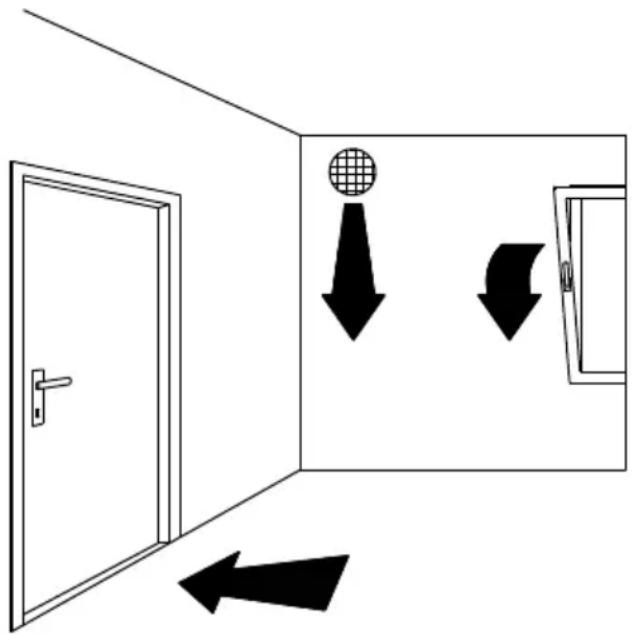
The heat pump can be used using the ambient air or air from other premises. The heat pump must be installed in a frost-free room. When selecting a place for installation, particular attention should be paid that the selected air intake location is dust free, because dust has adverse effects on the heat pump performance. When selecting the place of installation, pay attention to the solidity of the wall – can it take the weight of the heat pump together with the weight of the water inside the boiler? Take all the necessary precautions to prevent the operation noise and vibrations from transferring through the walls to the premises where this would be disturbing (bedrooms, rest areas). Do not install the heat pump and its air intake in premises with other air consumption appliances (gas boilers, solid-fuel fireplaces, dust extraction appliances etc.) During installation, please bear in mind the minimum distances from the wall, ground and ceiling. The condensate outlet from the heat pump is placed on the bottom left side in the form of a plastic tube with an external diameter of 18 mm. This tube should be connected to the external condensate outlet pipe and led to the sewage system or a container. The quantity of condensate depends on air temperature and humidity when the heat pump is in operation.
To prevent pressure depression in the building, fresh air must be regularly supplied to the premises. The desired rate of air exchange for a residential building is 0.5. This means that the entire quantity of air in the building is exchanged every two hours.
Connecting the heat pump to the same pipeline as the kitchen extractor fan or taking air out of several smaller apartments or suites is not allowed.
natural_image
Simple line drawing of a door opening with directional arrows indicating movement or flow (no text or symbols)Fig. 3: Ventilation
To minimize the transfer of noise and vibrations through walls into the premises where this would be disturbing (bedrooms, rest areas), please take the following measures:
- install flexible joints for hydraulic connections
- install a flexible tube for the pipeline of inlet/outlet air
- plan vibration insulation for wall openings
- plan noise dampers for inlet/outlet air
- pipelines for inlet/outlet air should be attached using noise dampers
- plan vibration insulation against the wall
a) Operation using ambient air
In this type of operation, the device heats domestic water using only the amount of energy generated by the air from the room where the device is installed. The heat pump must be installed in a ventilated, frost-free room, possibly in the vicinity of other heating sources. For optimal performance of the heat pump, we recommend a sufficiently large and well ventilated room with the temperature ranging between 15 °C and 25 °C. It is vital to ensure sufficient intake of air in the room. Elbows must be installed on the heat pump and turned so that they prevent the mixing of air. Heat losses are greater in premises with colder air.
If the heat pump is installed in a frost-free room and the temperature is under 7 °C , the heat pump operates in the normal mode of operation.
min 20 cm
min 25 cmmin 2
min 75 cm
min 150 cm
Fig. 4: Minimum requirements for the installation of HP
b) Operation using air from other premises
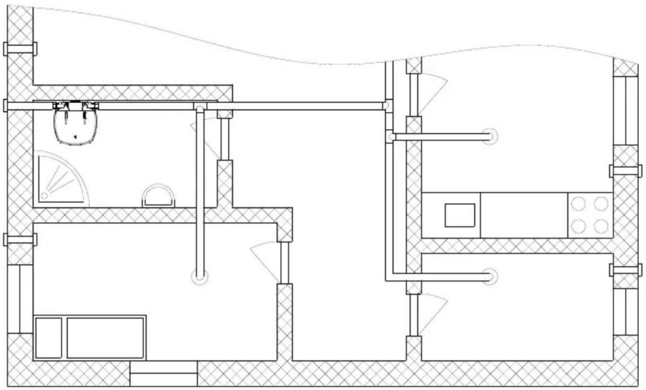
In this type of operation, the heat pump uses air from other premises via a pipeline system. It is advisable to insulate the pipeline system to prevent the formation of condensate. In case of using air from outside, the external part must be covered so as to prevent the intrusion of dust or snow into the appliance.
Besides the drag in the pipes and elbows, the user should be aware that increased drag also increases noise levels.
In case of using air from outside, the user should adhere to the minimum diameter of the pipes 125 mm or 150×70 .
To make sure the operation of the pump is effective at all times, you can install dampers to take air from the premises and then return it either to the premises or outside. If the temperature of air is under -7 °C, heaters for the heating of domestic water are switched on. The heat pump operates in reserve mode.
natural_image
Architectural floor plan showing room layouts and structural elements (no text or labels)Fig. 5: Possible installation of a heat pump
PRESSURE LOSS IN CASE OF USING THE PIPELINE SYSTEM
In planning the pipeline system for the inlet and outlet of air to and from the heat pump, the key element is to take into account the aerodynamic character of the fan which also causes the loss of static pressure.
Presentation of the diagram of aerodynamic characteristics for different speeds of the fan
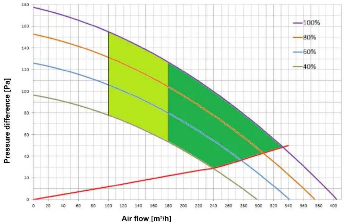
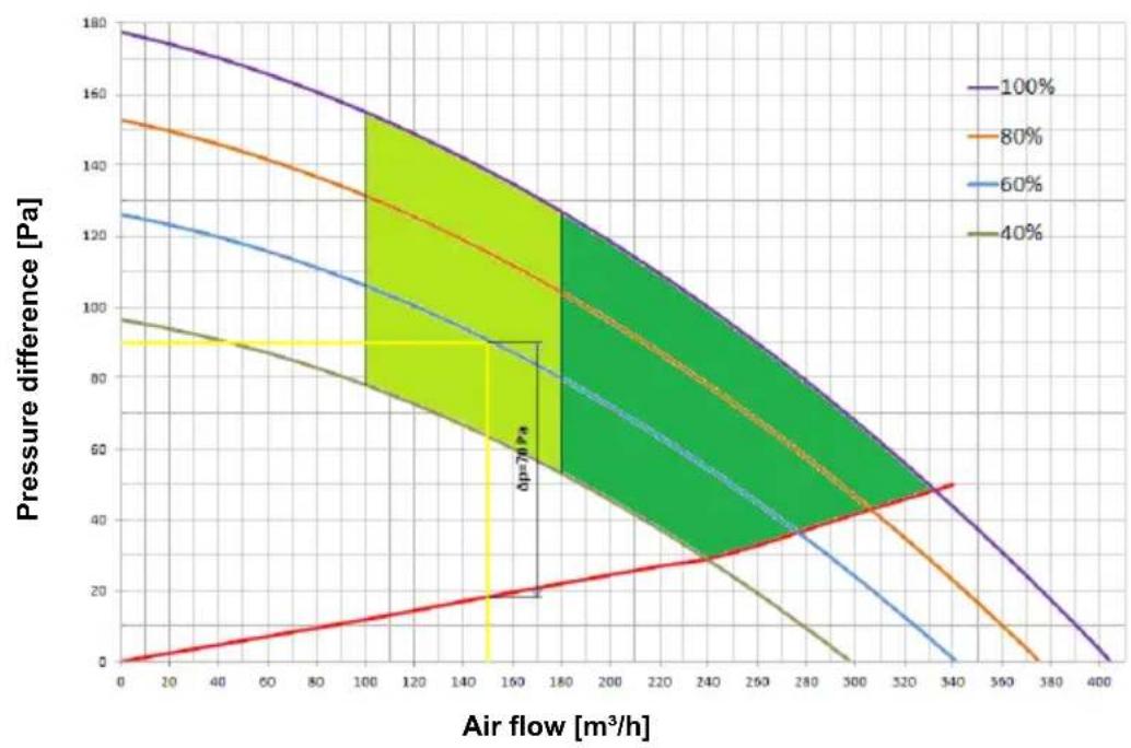
The diagram (Diagram 1) includes aerodynamic characteristics of the operation of the fan. The top (purple) line represents the curve of air flow depending on the pressure drop at maximum speed of the fan (100 %). The bottom (brown) line represents the operation of the fan at minimum speed (40 %). The curves between (60 %, 80 %) represent the aerodynamic characteristics at lowered revolutions of the fan. The bottom (red) line that lies between points (0,0) and (340,50) represents the internal drop of static pressure created by the evaporator alone, without overloading the pipeline system. This pressure drop cannot be eliminated.
area
| Air flow [m³/h] | 100% | 80% | 60% | 40% | | --------------- | ---- | --- | --- | --- | | 0 | 175 | 150 | 125 | 95 | | 20 | 170 | 145 | 120 | 90 | | 40 | 165 | 140 | 115 | 85 | | 60 | 160 | 135 | 110 | 80 | | 80 | 155 | 130 | 105 | 75 | | 100 | 150 | 125 | 100 | 70 | | 120 | 145 | 120 | 95 | 65 | | 140 | 140 | 115 | 90 | 60 | | 160 | 135 | 110 | 85 | 55 | | 180 | 130 | 105 | 80 | 50 | | 200 | 125 | 100 | 75 | 45 | | 220 | 120 | 95 | 70 | 40 | | 240 | 115 | 90 | 65 | 35 | | 260 | 110 | 85 | 60 | 30 | | 280 | 105 | 80 | 55 | 25 | | 300 | 100 | 75 | 50 | 20 | | 320 | 95 | 70 | 45 | 15 | | 340 | 90 | 65 | 40 | 10 | | 360 | 85 | 60 | 35 | 5 | | 380 | 80 | 55 | 30 | - | | 400 | - | - | - | - |- Area of more efficient use – volumetric flow of air is higher here, which requires a lower pressure drop (channel system with minimum pressure drop). Fan is set to higher speeds.
- Operating area with a normal air flow with respect to the pressure drop and fan setting.
Diagram 1: Aerodynamic characteristics
Air inlet and outlet pipeline system
When connecting the sanitary heat pump to an existing pipeline system, we use the basic pipe elements that we connect into a pipeline system for air inlet and outlet. The air pipeline should consist of round pipes with an inner diameter of 125 mm, or rectangular pipes with a cross section of 150×70 mm.
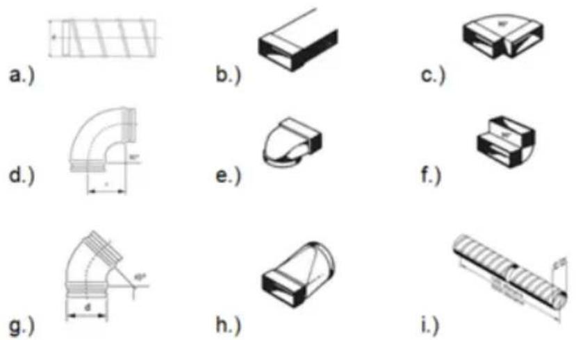
Fig. 6: Schematic demonstration of the basic elements in a pipeline system for inlet and outlet of air
Calculation of pressure drops
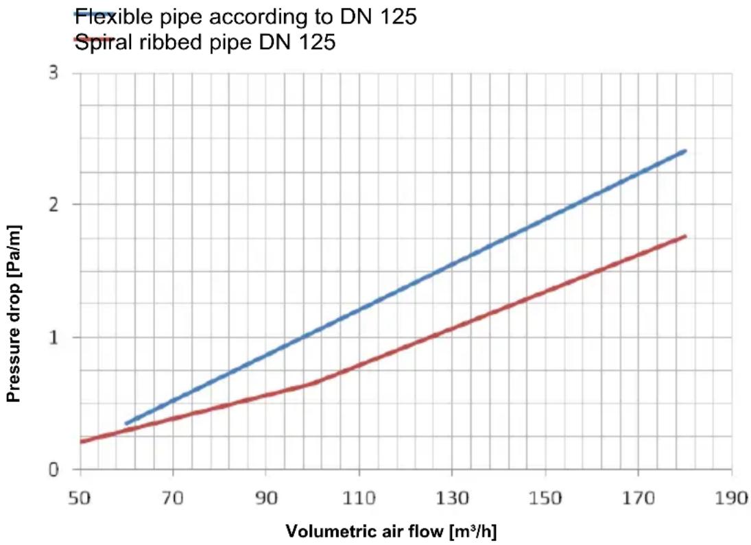
The values of total static pressure drop can be calculated by adding up the losses from individual elements built into the air pipeline system and the internal static pressure. The values of static pressure drops of individual elements (static pressure drops of elements relate to the internal diameter 125mm or 150x70mm ) are shown in Table no. 2.
| Type of element | Value of static pressure loss |
| a.) Spiral ribbed pipe | Diagram 2 |
| b.) Rectangular pipe □150x70 mm | Diagram 2 (according to DN 125) |
| c.) Rectangular elbow - horizontal 90° | 5 Pa |
| d.) Elbow 90° 4 Pa | |
| e.) Angular reducer ø125 to □150x70 5 Pa | |
| f.) Rectangular elbow - vertical 90° 5 Pa | |
| g.) Elbow 45° 3 Pa | |
| h.) Reducer ø125 to □150x70 3 Pa | |
| i.) Flexible tube | Diagram 2 |
| j.) Air intake grid 25 Pa |
Table no. 2: Types of elements and corresponding pressure loss values
line
| Volumetric air flow [m³/h] | Flexible pipe pressure drop [Pa/m] | Spiral ribbed pipe pressure drop [Pa/m] | | -------------------------- | ----------------------------------- | ---------------------------------------- | | 50 | 0.3 | 0.2 | | 70 | 0.6 | 0.4 | | 90 | 0.9 | 0.6 | | 110 | 1.2 | 0.8 | | 130 | 1.5 | 1.0 | | 150 | 1.8 | 1.2 | | 170 | 2.1 | 1.4 | | 185 | 2.3 | 1.6 |Diagram 2: Value of the static pressure drop for selected pipes
| Number of elements | p (Pa) | p (Pa) | |
| Rectangular elbow horizontal 90° | 4 | 5 | 20 |
| Flexible tube (DN125) | 13.5 | 1.85(at 150 m3/h) | 25 |
| Air intake grid | 1 | 25 | 25 |
| Total: | 70 |
Table 3: Example of pressure drop calculation
Note:
As mentioned above, the total loss of static pressure, which can be calculated by adding up the losses of individual elements built into the pipeline system, may not exceed 95 Pa. If they do, the values of COP start dropping more dramatically.
DETERMINING THE FAN SETTING
When pressure drop is determined, select the mode in which the fan will operate. This determines the speed of the fan. The mode is selected using Diagram no. 1, which shows the aerodynamic characteristics of the fan depending on the air flow and pressure drop in the pipeline*.
Note:
*Pressure drop in the pipeline – in diagram 1 this is marked as pressure difference.
Zone of operation of the sanitary heat pump
On diagram 1 there are two zones of operation of the sanitary heat pump among the curves:
- The dark green zone represents the area of use with higher efficiency. The volumetric air flow is higher in this zone, which requires a lower pressure drop (channel system version with minimum pressure drop).
- The light green zone represents the area of use with lower air flow in relation to the pressure drop and fan setting.
Noise
Like the aerodynamic characteristics rise from the lowest to the highest, the noise increases as well. Between the aerodynamic characteristics 80% and 100% there is a zone with increased noise.
Checking the calculation of pressure drop
Determining the aerodynamic characteristics based on the calculation of pressure drop while taking into account individual elements of the pipeline and air flow is an iteration. Once the aerodynamic characteristic has been determined and set, we must measure the air flow in the pipeline. If the air flow does not correspond to the ventilation system, we select the next higher or lower aerodynamic characteristic that corresponds to the ventilation system.
Selecting the operating point of the fan for the ventilation system
When determining the speed of the fan, we must know the maximum air flow for ventilation and pressure drop caused by the pipeline. In Diagram 1, find the desired air flow and draw a vertical line, then draw a horizontal line at the pressure drop that you have calculated (based on the existing pipeline). Select the fan characteristic curve that lies the closest to the point where the lines cross.
Example of selecting the aerodynamic characteristic
In diagram 3 at air flow of 150 m^3/h draw a vertical line. The pipeline represents 70 Pa of pressure drop, which is added to the below (red) line**. Total pressure drop is thus 90 Pa. Draw a horizontal line at the pressure drop of 90 Pa. The point where the lines meet lies on the curve that corresponds to 60% speed of the fan. This is the standard setting of the fan that has also been preset by the manufacturer.
Note:
**Line, represents the internal static pressure drop created by the evaporator.
line
| Air flow [m³/h] | 100% | 80% | 60% | 40% | | --------------- | ---- | --- | --- | --- | | 0 | 180 | 150 | 125 | 95 | | 160 | 130 | 110 | 85 | 60 | | 340 | 50 | 30 | 0 | 0 |Diagram 3: Example of determining aerodynamic characteristic
CONNECTION TO WATER SUPPLY MAINS
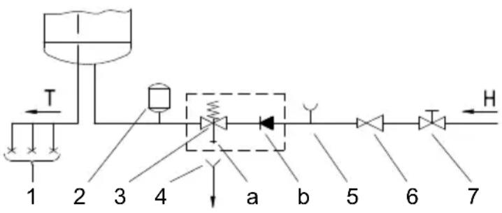
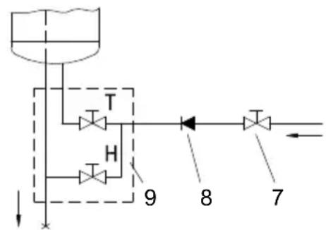
Water inlet and outlet on the heat pump are marked with colours. Cold water inlet is marked with blue, and warm water outlet is marked with red. The heat pump is designed for connection to indoor water supply mains without using the relief valve if the pressure in the supply mains is lower than 0.6 MPa (6 bar). If the pressure is higher, a relief valve needs to be installed so as to provide that the pressure at the inlet to the hot water tank does not exceed the nominal pressure.
Installing a safety valve is mandatory in order to assure safe operation. The valve prevents an increase of the pressure in the boiler by any more than 0.1 MPa (1 bar) above the rated pressure. The outflow nozzle on the safety valve must have an outlet into the atmosphere. To assure correct operation of the safety valve, the valve must be regularly checked.
When checking the valve, push the lever or unscrew the nut of the valve (depending on the type of the valve) and open the drain from the safety valve. Water must flow from the valve nozzle, showing that the valve operation is faultless. During the heating of water, the water pressure in the hot water tank is increased up to the level preset in the safety valve. Since the system prevents backflow of water into the water supply mains, water may be dripping from the outlet opening on the safety valve. The dripping water may be drained via trap into the drains; the trap is mounted under the safety valve. The outlet pipe, which is mounted under the safety valve, must be directed downwards, in a place with a temperature above freezing.
If the installation does not allow draining of the water from the safety valve into the drains, dripping can be avoided by installing an expansion vessel onto the heat pump inlet pipe. The volume of the expansion vessel must be ca. 3% of the hot water tank volume.
flowchart
graph LR
    1 --> T
    T --> 2
    2 --> 3
    3 --> 4
    4 --> a
    a --> b
    b --> 5
    5 --> 6
    6 --> 7
    7 --> H
Fig. 7: Closed (pressure) system
flowchart
graph TD
    A["Container Tank"] --> B["T"]
    B --> C["H"]
    C --> D["Valve 9"]
    D --> E["Valve 8"]
    E --> F["Valve 7"]
    style A fill:#f9f,stroke:#333
    style B fill:#ccf,stroke:#333
    style C fill:#cfc,stroke:#333
    style D fill:#fcc,stroke:#333
    style E fill:#cff,stroke:#333
    style F fill:#ffc,stroke:#333
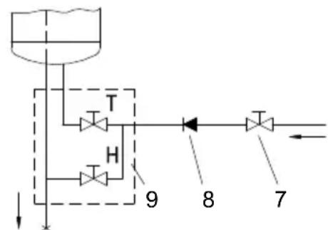
Fig. 8: Open (non-pressure) system
Legend:
1 - Pressure mixer taps
2 - Expansion tank
3 - Safety valve
a - Test valve
b - Non-return valve
4 - Funnel with outlet connection
5 - Checking fitting
6 - Pressure reduction valve
7 - Closing valve
8 - Non-return valve
9 - Low pressure mixer tap
H - Cold water
T - Hot water
CONNECTING THE HEAT PUMP TO THE POWER SUPPLY NETWORK
Before connecting to the power supply network, install a power supply cord in the heat pump, with a min. diameter of 1.5 mm^2 (H05VV-F 3G 1.5 mm^2 ). To do this, remove the protective cover from the heat pump. The cover is attached using two screws (Fig. 9). Connecting the heat pump to the power supply network must take place in accordance with the standards for electric appliances. To comply with the national installation regulations, an all poles disconnect switch must be installed between the heat pump and the power supply network.
Fig. 9: Protective cover
scatter
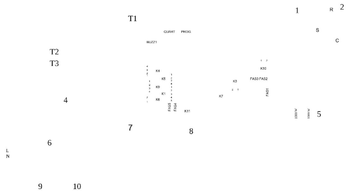
| Label | Value | |---|---| | T1 | 1 | | R | 2 | | S | | | C | | | BUZZ1 | | | T2 | | | T3 | | | 4 | | | 7 | | | 8 | | | 6 | | | 9 | 10 | L NFig. 10: Electrical circuit diagram
Legend:
T1 - Bar with sensors
T2 - Evaporator – temp. sensor
T3 - Air temperature sensor
1 - 4-way valve
2 - Compressor
4 - Fan
5 - Electric heating element
6 - Thermal cut-out
7 - Magnesium anode
8 - LCD touch screen
9 - Boiler - ground
10 - Housing - ground
$$ (2 \times 1 0 0 0 \mathrm{W}) $$
HEAT PUMP OPERATION
The heat pump can be operated using an LCD touch screen (Fig. 11). If you press anywhere on the screen, the screen lights up. When the screen is lit up, the operation fields are active.
When the heat pump is connected to the water and power supply mains and the boiler is filled with water, the heat pump is ready to be used. The heat pump heats the water in the range 10 °C - 55 °C . From 55 °C - 75 °C the water is heated by electrical heaters.
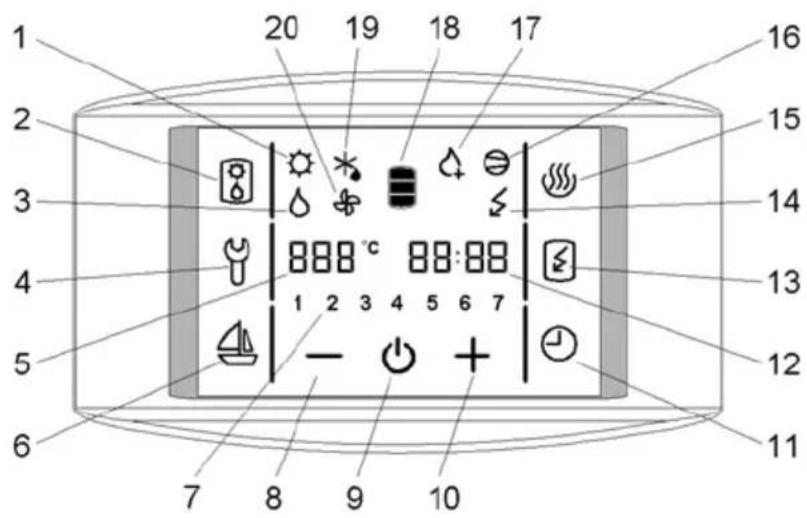
Fig.11: LCD touch screen
Legend:
1 - Signalization of the operation of solar collectors**
2 - alternative source of heating turned on (heaters)
3 - Signalization of the operation of the oil boiler**
4 - Indication, overview of operation errors, entrance into the service menu
5 - Display and setup of temperature in °C
6 - Start and setup of the VACATION programme
7 - Day of the week
(1 .. Monday, ..., 7 .. Sunday)
8 - Reducing the value
9 - Heat pump on/off switch
10 - Increasing the value
11 - TIMER start and setup
12 - Time setup and display
13 - Start-up of quick heating "TURBO"
14 - Indicator of the heating element operation
15 - Start-up of heating to the maximum temperature level
16 - Signalization of compressor operation
17 - Signalization of anti-legionella programme operation
18 - Warm water quantity display
19 - Signalization of defrosting
20 - Signalization of fan operation
** function is not used in versions TC-ZNT
Starting/stopping the heat pump
• To start the heat pump hold field no. 9.
When the appliance is switched on, the fan starts first and operates for one minute (symbol no. 20 is displayed). If the temperature of inlet air is appropriate, the controlling unit switches on the compressor and the heat pump operates in normal
mode (symbols 16 and 20 are displayed). The heat pump is on, the screen remains unlit and inactive.
In 60 seconds after the last touch of the screen, the illumination and activity of the screen are turned off, but that does not affect the operation of the heat pump.
Pressing anywhere on the screen re-activates the screen and its illumination.
If trying to start up at a lower temperature, please see chapter "Operation at lower temperatures".
- By holding field no. 9, the heat pump is switched off. The appliance stops functioning and the only field visible on the screen is field no. 9. (If you switch off the heat pump for a longer period of time, the water must be drained from the pump if there is any danger of freezing).
Power failure protection
In case of power failure, the settings remain stored for up to 23 hours.
After restarting, the heat pump operates in the same mode it was operating in before the power failure.
Operation at lower temperatures
When the appliance is switched on, the fan starts first and operates for one minute (symbol no. 20 is displayed). If the temperature of inlet air is lower than -7 °C, the fan is turned off. Domestic water is heated with heaters. The heat pump operates in the reserve mode (symbol no. 14 is displayed). The possibility of switching to normal mode is checked every 2 hours by switching on the fan for one minute. If the temperature of inlet air is higher than -7 °C, the heat pump switches to normal mode of operation (symbols 16 and 20 are displayed). The heaters switch off. The heat pump is on, the screen remains unlit and inactive.
At lower air temperatures, the evaporator defrosting cycle is started if necessary.
Symbol no. 19 is displayed on the screen. The fields 2, 4, 6, 11, 13 and 15 remain inactive. Defrosting takes place until the conditions for normal operation of the heat pump are achieved.
After successful defrosting, the heat pump returns to normal operation (symbols 16 and 20 are displayed).
If defrosting is unsuccessful after two consecutive attempts, the controlling unit displays an error message. Field no. 4 starts flashing, accompanied by warning beeps. By pressing field no. 4 the warning beeps can be turned off. Error code E247 appears in field no. 12 and the pump switches automatically to heating with electric heaters. The screen displays symbol no. 14. The error code can be deleted at any time by pressing field no. 4. Field no. 12 resumes to displaying time.
Setting the clock and day of the week
- Hold field no. 12, until field no. 7 shows a flashing number of the day of the week.
- By pressing + or – you can set the number of the day of the week (1 – Monday, ..., 7 – Sunday).
- Press field no. 12 again (flashing hour setting is displayed).
- By pressing + or – set the hour (by holding + or – you can speed up the setting).
- Press field no. 12 again.
-
Flashing minute setting is displayed.
-
By pressing + or – set the minutes (by holding + or – you can speed up the setting).
- The setting is stored when you press field no. 12, or when the field stops flashing.
Setting the temperature
- Press field no. 5 (the set temperature starts blinking).
- By pressing + or – you can change the temperature setting from 10 °C to 75 °C (preset to economic temperature of 55 °C).
- The setting is stored by pressing field no. 5 again, or when field no. 5 stops flashing. After a few seconds, the display shows the actual temperature.
- In case of power failure, the last stored value is restored.
Switching on the "TURBO" mode
- If you need more warm water than the heat pump can heat up in a short period of time, press field no. 13 (switches on the "TURBO" mode). The heat pump and heater work simultaneously. The screen shows symbols no. 14, 16 in 20. When the temperature reaches 55^ the heat pump returns to the mode used before the "TURBO" mode.
Switching on the "HOT" mode
- If you want to heat the water to the maximum temperature of 75 °C, press field no. 15. The heat pump will heat water to 55 °C. The screen displays symbols no. 16 in 20. When the temperature in the boiler reaches 55 °C the electric heater turns on to heat the temperature up to 75 °C. The screen displays the symbol no. 14. When the temperature reaches 75 °C the heat pump returns to the mode used before the "HOT" mode.
Display of the quantity of water in the heat pump
Field no. 18 shows the following symbol :
- low quantity of warm water

- no warm water
- high quantity of warm water

Setting the vacation mode
In the vacation mode, you can set the number of days (maximally 100), when the heat pump shall maintain the minimal temperature of water (approximately 10 °C ).
- Hold field no. 6 for a while (fields 5 and 6 start to flash).
- By pressing fields + or – you can set the number of vacation days shown in field no. 5.
- By pressing field no. 6 again, or when field no. 6 stops flashing, the set number of days is stored.
- If you set the value to 0, then the heat pump will resume its normal operating mode after confirming the setting, and illumination of field no. 6 will turn off.
- After the set number of days has elapsed, the heat pump returns to the normal mode and illumination of field no. 6 turns off.
Setting the TIMER mode
In the TIMER operating mode, you can set the times when the heat pump will start and stop. For each timer combination you can set up to three time periods in which the heat pump will not heat the water.
a) Setting the timer combinations
- Hold field no. 11 for a while (fields 7 and 11 start to flash).
- By pressing fields + or – choose among three timer modes of operation:
- Timer mode of operation of the heat pump for the entire week (numbers 1-7 flash in field no. 7),
- Timer mode of operation of the heat pump for Monday to Friday and Saturday to Sunday (numbers 1-5 and then 6 and 7 flash in field no. 7),
-
Timer mode of operation of the heat pump for each day at a time (individual numbers 1-7 flash in field no. 7).
-
To set the time, press field no. 12.
- On the field no. 5, the text 1OF appears and field no. 12 starts to blink.
- By pressing fields + or – set the time of shutdown.
- Press field no. 12 again.
- On the field no. 5, the text 1ON appears and field no. 12 starts to blink.
- By pressing fields + or – set the time of start-up.
- By pressing field no. 12 again, you can use the above procedure to set the second and third period.
- By pressing field no. 12 again, or when field no. 6 stops flashing the set number of days is stored. Again, press field no. 12.
b) Activation, deactivation of timer
- By pressing field no. 11, you can activate the set timer mode.
- The heat pump heats the water in the ON periods (to the set temperature) and in the OFF periods, it does not heat the water.
- By pressing field no. 11 again, you can deactivate the set time mode of operation.

Fig. 12: Time periods
Anti-legionella function
- Works only when the heat pump is switched on. When activated, symbol no. 17 is displayed.
- Automatic activation: every 2 weeks of operation of the heat pump, if the temperature of water did not exceed 65^ for one straight our or more in the previous two-week period.
- Anti-legionella programme can be activated manually by pressing field no. 15 (heating of water to the temperature of 75^ ).
Operation signalization:
Anti-legionella programme:
Programme on – control field no. 17 is displayed
Programme off – control field no. 17 is not displayed
electric heaters:
heaters on - control field no. 14 is displayed
heaters off – control field no. 14 is not displayed
heat pump:
heat pump is heating water – control field no. 16 is displayed
heat pump is not heating water – control field no. 16 is not displayed
on/off:
heat pump is on – next to field no. 9 other fields are also visible on the screen
heat pump is off – only field no. 9 is visible on the screen
defrosting:
heat pump is in the defrosting mode – control field no. 19 is displayed
heat pump is not in the defrosting mode – control field no. 19 is not displayed
fan on/off:
fan is on – control field no. 20 is displayed
fan is off - control field no. 20 is not displayed
alternative source of heat – electric heaters: (field no. 2)
switched to the electric heaters - control field no. 14 is displayed
fields 1 and 3 are not active in these versions of the heat pump
Access to the service level
- By holding field no. 4 on the display (figure 11), the function "service mode" is turned on.
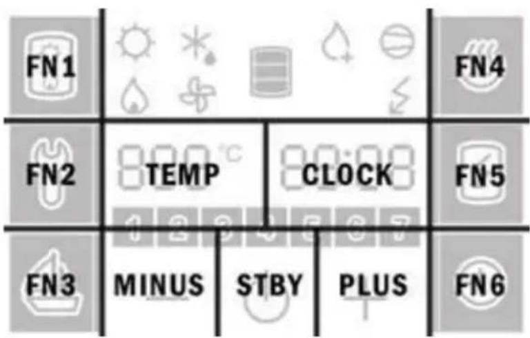
- The introductory menu appears with code written in the CLOCK field; the service code can be entered using the keys FN1, FN2, FN3, FN4, FN5 and FN6, which correspond to numbers 1,2,3,4,5,6.
flowchart
graph TD
    FN1["FN1"] --> A["Weather Icon"]
    FN1 --> B["Light Bulb icon"]
    FN1 --> C["Light Source icon"]
    FN2["FN2"] --> D["TEMP Icon"]
    FN2 --> E["CLOCK Icon"]
    FN3["FN3"] --> F["MINUS Icon"]
    FN3 --> G["STBY Icon"]
    FN3 --> H["PLUS Icon"]
    FN4["FN4"] --> I["Light Bulb icon"]
    FN5["FN5"] --> J["Light Source icon"]
    FN6["FN6"] --> K["Plus Icon"]
Fig. 13: Fields on the display
- If none of the fields are pressed for 10 s the menu automatically returns to normal functioning.
- If the code is entered incorrectly, the programme automatically exits the
introductory menu.
- When the code is entered correctly, the first parameter appears. The number on the right consecutive number of the parameter and the number on the left is its value.
- The first parameter :00 is the version of the programme code that is purely of informative nature.
- By pressing the right number (the CLOCK field on Figure 13) the next parameter is displayed.
Installation menu: CODE 1166:
After the installation menu code is entered correctly, the following parameters can be accessed:
00 programme code version (informative parameter)
21 setting the speed of fan
27 setting low-temperature mode
Setting the speed of the fan (parameter :21)
When the parameter (:21) is selected, press (+) or (-) to set the desired fan speed (40 -100%). On the left side (field 5) the numeric value of the setting is displayed. When the desired speed of the fan is set, it is stored after a short delay or after pressing field no. 4.
Setting the low-temperature mode of operation of the heat pump (parameter :27) When parameter :27 is selected, press (+) or (-) to determine the temperature mode of operation of the heat pump, which depends on the version of the heat pump. The low-temperature mode can only be set if the heat pump version allows it!**** On the left side (TEMP field) the set mode is displayed:
Yes – heat pump version TC ZNT, heat pump operation mode (up to -7^ ), the system includes a 4-way valve
No – heat pump version TC Z, heat pump operation mode 7°C, the system does not include a 4-way valve
Note:
****The low-temperature mode of operation of the heat pump is a setting that the installer can only set if the version of the heat pump is appropriate. When replacing the electronic module, the mode of operation must be selected in such a way that it suits the version of the heat pump!
SERVICE AND MAINTENANCE
If installed and used correctly, the heat pump will last for years without service.
The exterior of the heat pump should be cleaned with a mild detergent solution. Do not use solvents or abrasive cleaning agents.
If the heat pump was exposed to dust, evaporator lamellas might become blocked, which can have a detrimental effect on the functioning of the heat pump. In this case the evaporator should be cleaned. The cleaning of the evaporator must be carried out by an authorised service provider.
By performing regular service inspections you can ensure faultless operation and a long life span of the heat pump. The tank corrosion warranty applies only if the prescribed regular anode inspections have been performed. The interval between individual inspections should not be longer than 36 months. Inspections must be carried out by an authorised service provider that logs each inspection on the product's warranty sheet. The service provider inspects the wear and tear of the anti-corrosion protective anode and cleans the limescale that accumulates inside the tank, depending on the quality, quantity and temperature of the water used. Service providers will also provide you with the following inspection date, depending on the state of the heat pump.
Before calling your service provider, check the following:
- Is everything OK with the power supply network?
- Is the air outlet obstructed?
- Is ambient temperature too low?
- Can you hear the operation of the compressor and fan?
- Pipeline system pressure drop
Do not try to eliminate malfunctions by yourself, call your nearest authorized service provider!
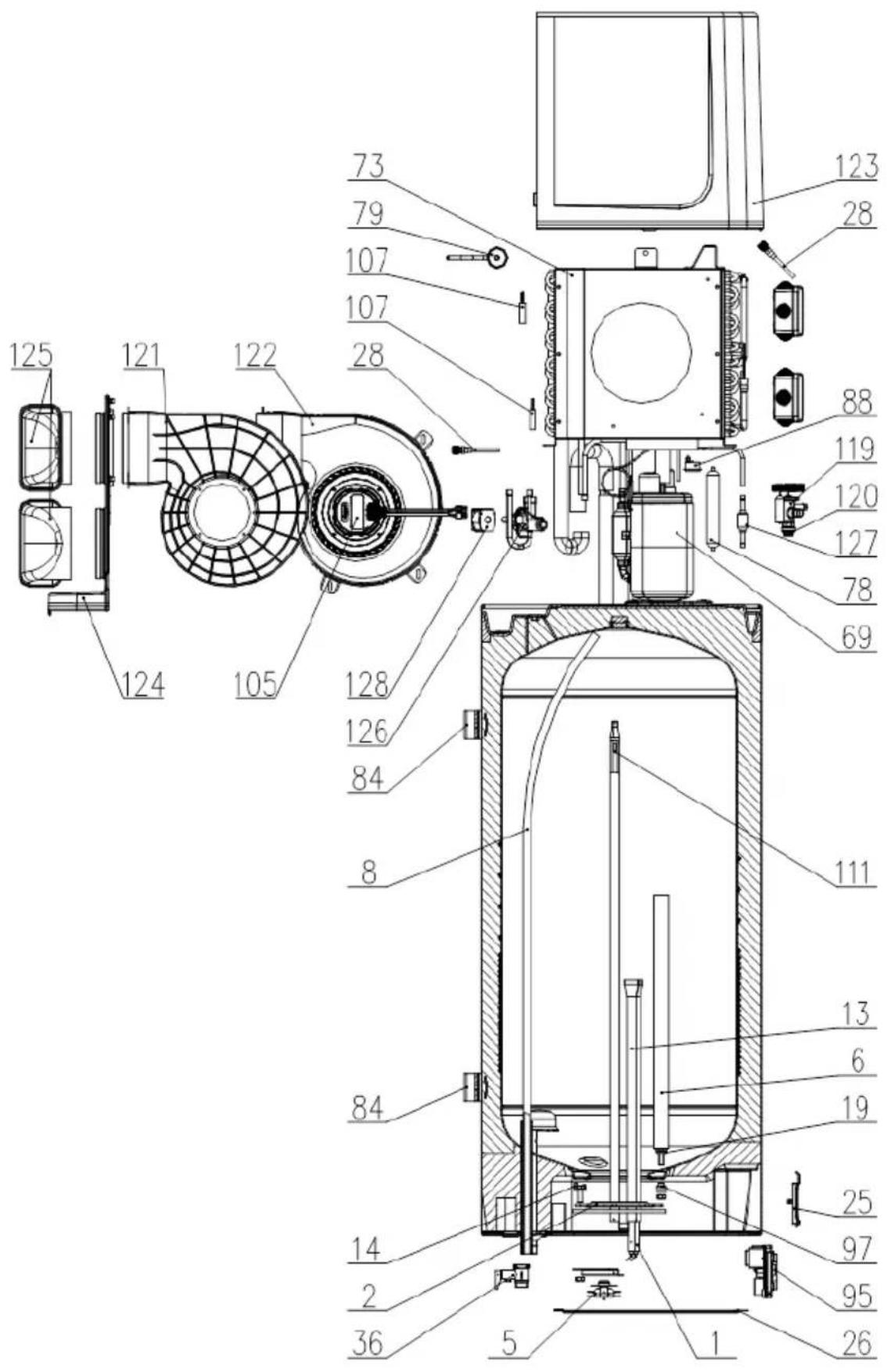
| Position | Ident | Spare part description | Quantity | Validity |
| 1 | 458697 | Heating Element 1000W | 2 | |
| 2 | 482939 | Gasket 160/94X8 | 1 | |
| 5 | 482993 | Bimetal Safety | 1 | |
| 6 | 268069 | Mg Anode D25,5X340-M8 | 1 | PAW-DHWM80ZNT PAW-DHWM120ZNT |
| 6 | 269182 | Mg Anode D25,5X450-M8 | 1 | PAW-DHWM120ZNT |
| 8 | 321302 | Outlet Tube 865mm | 1 | PAW-DHWM80ZNT |
| 8 | 321287 | Outlet Tube 1015mm | 1 | PAW-DHWM100ZNT |
| 8 | 321289 | Outlet Tube 1185mm | 1 | PAW-DHWM120ZNT |
| 13 | 404077 | Heater Flange 80L | 1 | PAW-DHWM80ZNT |
| 13 | 404053 | Heater Flange 100L | 1 | PAW-DHWM100ZNT |
| 13 | 404046 | Heater Flange 120L | 1 | PAW-DHWM120ZNT |
| 14 | 482940 | Screw Holder | 6 | |
| 19 | 482950 | Gasket D18,8/D7,6X3 | 1 | |
| 25 | 478222 | Control Panel | 1 | |
| 26 | 757132 | Bottom Cover | 1 | |
| 28 | 321732 | Filling Valve Assy | 2 | |
| 69 | 405139 | Compressor | 1 | |
| 88 | 419383 | Thermal Cutout | 1 | |
| 73 | 392473 | Evaporator | 1 | |
| 78 | 364934 | Drying Filter 30 g | 1 | |
| 79 404919 | Capacitor 10 μF | 1 | ||
| 84 | 757137 | Wall Bracket | 2 | |
| 95 | 405088 | Electronics | 1 | |
| 97 | 487074 | Insulating Bush D17/D8X5 | 1 | |
| 105 | 404083 | Centrifugal Fan | 1 | |
| 107 | 334192 | Temperature Sensor | 2 | |
| 111 | 345664 | Sensor Strip 80L | 1 | PAW-DHWM80ZNT |
| 111 | 345665 | Sensor Strip 100L | 1 | PAW-DHWM100ZNT |
| 111 | 345666 | Sensor Strip 120L | 1 | PAW-DHWM120ZNT |
| 119 | 451724 | Thermal Expansion Valve TUB-R134 | 1 | |
| 121 | 404081 | Air Duct Left | 1 | |
| 122 | 404082 | Air Duct Right | 1 | |
| 123 | 439625 | Front Protection Cap | 1 | |
| 124 | 364941 | Back Protection Cap | 1 | |
| 125 | 429797 | Connection Elbow D125/150X70 | 2 | |
| 126 | 392462 | 4-Way Valve | 1 | |
| 127 | 451725 | Check Valve | 1 | |
| 128 | 443882 | 4-Way Valve Coil | 1 | |
OPERATION ERRORS
Despite careful production and control, the heat pump can produce errors that must be solved by an authorised service provider.
Indicator of errors
- In case of an error on the appliance, the beeper starts beeping and field no. 4 starts flashing. When you press field no. 4 the error code is displayed in field no. 12.
| Error Description of error Solution | ||
| E004 Freezing. The error appears if the temperature in the heat pump is below 4 °C. | Call the service. | |
| E005 Overheating (temperature >85 °C, electronic regulator failure). | Unplug the heat pump from the power supply. Call the service. | |
| E006 | Mg anode error. | Call the service (heat pump functions normally). |
| E007 | Volume and/or temperature sensors error. | Call the service. |
| E042 | Anti-legionella function error. | Press field no. 4 to restart. |
| E247 | Defrosting error. | Automatically turns on heating with the electric heater. When the error is deleted, the aggregate resumes its normal operation. |
| E361 | External air sensor error. | Call the service (automatically switches to the electric heater). |
| E363 | Defrosting sensor error. | Call the service (automatically switches to the electric heater). |
HINWEISE!
natural_image
Simple line drawing of a door opening with directional arrows indicating movement or flow (no text or symbols)Bild 3: Belüftung
natural_image
Architectural floor plan showing room layouts and structural elements (no text or labels)line
| Luftstrom [m³/h] | 100% | 80% | 60% | 40% | | ---------------- | ---- | --- | --- | --- | | 0 | 175 | 150 | 125 | 95 | | 100 | 155 | 135 | 110 | 80 | | 240 | 125 | 105 | 80 | 30 | | 340 | 50 | 40 | 0 | 0 |line
| Luftstrom [m³/h] | 100% | 80% | 60% | 40% | | ---------------- | ---- | --- | --- | --- | | 0 | 180 | 140 | 125 | 95 | | 160 | 130 | 110 | 90 | 60 | | 340 | 60 | 40 | 20 | 0 |natural_image
Diagram showing a door opening with directional arrows indicating movement or flow, no text or symbols presentFig 3: Ventilazione
natural_image
Architectural floor plan showing room layouts and structural elements (no text or labels)line
| Flusso d'aria [m³/h] | 100% | 80% | 60% | 40% | | --------------------- | ---- | --- | --- | --- | | 0 | 180 | 150 | 125 | 95 | | 160 | 130 | 110 | 85 | 70 | | 340 | 60 | 40 | 20 | 50 | | 400 | 0 | 0 | 0 | 0 |natural_image
Simple line drawing of a door opening with directional arrows indicating movement or flow (no text or symbols)natural_image
Architectural floor plan showing room layouts and structural elements (no text or labels)line
| Caudal de aire [m³/h] | 100% | 80% | 60% | 40% | | --------------------- | ---- | --- | --- | --- | | 0 | 180 | 150 | 125 | 95 | | 190 | 130 | 110 | 85 | 60 | | 340 | 50 | 30 | 0 | 0 |natural_image
Simple line drawing of a door opening with directional arrows indicating movement or flow (no text or symbols)Fig. 3: Ventilation
natural_image
Architectural floor plan showing room layouts and structural elements (no text or labels)Fig. 5: Mulig installation af en varmepumpe
TRYKTAB VED BRUG AF R∅RSYSTEMET
line
| Luftstrøm [m³/t] | 100% | 80% | 60% | 40% | | ---------------- | ---- | --- | --- | --- | | 0 | 180 | 150 | 125 | 95 | | 160 | 150 | 125 | 100 | 75 | | 340 | 100 | 80 | 60 | 40 | | 400 | 50 | 40 | 20 | 0 |Fig. 7: Lukket system (under tryk)
flowchart
graph TD
    A["Container Tank"] --> B["T"]
    A --> C["H"]
    B --> D["Valve 9"]
    C --> E["Valve 8"]
    D --> F["Directional Arrow"]
    E --> G["Directional Arrow"]
    F --> H["Downward Arrow"]
    G --> I["Downward Arrow"]
Fig. 8: Åbent system (ikke under tryk)
Signaturforklaring:
1 - Trykblandingsbatteri
2 - Ekspansionstank
3 - Sikkerhedsventil
a - Testventil
b - Kontraventil
| Position | Ident. | Beskrivelse af reservedel | Mængde | Gyldighed |
| 1 | 458697 | Varmelegeme 1000W 230V | 2 | |
| 2 | 482939 | Pakning 160/94X8 | 1 | |
| 5 | 482993 | Sikkerhedsanordning i bimetal | 1 | |
| 6 | 268069 | Offeranode D25,5X340-M8 | 1 | PAW-DHWM80ZNTPAW-DHWM120ZNT |
| 6 | 269182 | Offeranode D25,5X450-M8 | 1 | PAW-DHWM120ZNT |
| 8 | 321302 | Afløbsslange 865mm | 1 | PAW-DHWM80ZNT |
| 8 | 321287 | Afløbsslange 1015mm | 1 | PAW-DHWM100ZNT |
| 8 | 321289 | Afløbsslange 1185mm | 1 | PAW-DHWM120ZNT |
| 13 | 404077 | Flange til varmelegeme 80L | 1 | PAW-DHWM80ZNT |
| 13 | 404053 | Flange til varmelegeme 100L | 1 | PAW-DHWM100ZNT |
| 13 | 404046 | Flange til varmelegeme 120L | 1 | PAW-DHWM120ZNT |
| 14 | 482940 | Skrueholder | 6 | |
| 19 | 482950 | Pakning D18,8/D7,6X3 | 1 | |
| 25 | 478222 | Kontrolpanel | 1 | |
| 26 | 757132 | Bunddæksel | 1 | |
| 28 | 321732 | Påfyldningsventilenh. | 2 | |
| 69 | 405139 | Kompressor | 1 | |
| 88 | 419383 | Varmeafbryder | 1 | |
| 73 | 392473 | Fordamper | 1 | |
| 78 | 364934 | Tørrefilter 30 g | 1 | |
| 79 | 404919 | Kondensator 10uF | 1 | |
| 84 | 757137 | Vægbeslag | 2 | |
| 95 | 405088 | Elektronik | 1 | |
| 97 | 487074 | Isolerende foring D17/D8X5 | 1 | |
| 105 | 404083 | Centrifugalblæser | 1 | |
| 107 | 334192 | Temperatursensor | 2 | |
| 111 | 345664 | Sensorstrimmel 80L | 1 | PAW-DHWM80ZNT |
| 111 | 345665 | Sensorstrimmel 100L | 1 | PAW-DHWM100ZNT |
| 111 | 345666 | Sensorstrimmel 120L | 1 | PAW-DHWM120ZNT |
| 119 | 451724 | Varmeekspansionsventil TUB-R134 | 1 | |
| 121 | 404081 | Luftkanal, venstre | 1 | |
| 122 | 404082 | Luftkanal, højre | 1 | |
| 123 | 439625 | Beskyttelsesdæksel, front | 1 | |
| 124 | 364941 | Beskyttelsesdæksel, bagside | 1 | |
| 125 | 429797 | Tilslutningsknæk D125/150X70 | 2 | |
| 126 | 392462 | 4-vejsventil | 1 | |
| 127 | 451725 | Kontraventil | 1 | |
| 128 | 443882 | 4-vejsventilspole | 1 |
DRIFTSFEJL
natural_image
Diagram showing a door opening with directional arrows indicating movement or flow, no text or symbols presentFig. 3: Ventilasjon
natural_image
Architectural floor plan showing room layouts and structural elements (no text or labels)Fig. 5: Mulig installering av en varmepumpe
TRYKKTAP VED BRUK AV R∅ROPPLEGG
line
| Luftgjennomstrømning [m³/h] | 100% | 80% | 60% | 40% | | --------------------------- | ---- | --- | --- | --- | | 0 | 190 | 150 | 125 | 95 | | 160 | 130 | 110 | 85 | 20 | | 340 | 50 | 40 | 20 | 50 | | 400 | 0 | 0 | 0 | 0 |SERVICE OG VEDLIKEHOLD
| Posisjon | Ident | Beskrivelse av reservedel | Mengde | Gyldighet |
| 1 | 458697 | Varmeelement 1000W | 2 | |
| 2 | 482939 | Pakning 160/94X8 | 1 | |
| 5 | 482993 | Bimetallsikkerhet | 1 | |
| 6 | 268069 | Offeranode D25,5X340-M8 | 1 | PAW-DHWM80ZNTPAW-DHWM120ZNT |
| 6 | 269182 | Offeranode D25,5X450-M8 | 1 | PAW-DHWM120ZNT |
| 8 | 321302 | Utløpsrør 865mm | 1 | PAW-DHWM80ZNT |
| 8 | 321287 | Utløpsrør 1015mm | 1 | PAW-DHWM100ZNT |
| 8 | 321289 | Utløpsrør 1185mm | 1 | PAW-DHWM120ZNT |
| 13 | 404077 | Varmeflens 80L | 1 | PAW-DHWM80ZNT |
| 13 | 404053 | Varmeflens 100L | 1 | PAW-DHWM100ZNT |
| 13 | 404046 | Varmeflens 120L | 1 | PAW-DHWM120ZNT |
| 14 | 482940 | Skrueholder | 6 | |
| 19 | 482950 | Pakning D18,8/D7,6X3 | 1 | |
| 25 | 478222 | Betjeningspanel | 1 | |
| 26 | 757132 | Bunndeksel | 1 | |
| 28 | 321732 | Påfyllingsventil | 2 | |
| 69 | 405139 | Kompressor | 1 | |
| 88 | 419383 | Termisk utkobling | 1 | |
| 73 | 392473 | Fordamper | 1 | |
| 78 | 364934 | Tørkefilter 30 g | 1 | |
| 79 404919 | Kondensator 10μF | 1 | ||
| 84 | 757137 | Veggfeste | 2 | |
| 95 | 405088 | Elektronikk | 1 | |
| 97 | 487074 | Isolasjonsforing D17/D8X5 | 1 | |
| 105 | 404083 | Sentrifugalvifte | 1 | |
| 107 | 334192 | Temperaturføler | 2 | |
| 111 | 345664 | Sensorstrips 80L | 1 | PAW-DHWM80ZNT |
| 111 | 345665 | Sensorstrips 100L | 1 | PAW-DHWM100ZNT |
| 111 | 345666 | Sensorstrips 120L | 1 | PAW-DHWM120ZNT |
| 119 | 451724 | Termisk ekspansjonsventil TUB-R134 | 1 | |
| 121 | 404081 | Luftsjakt venstre | 1 | |
| 122 | 404082 | Luftsjakt høyre | 1 | |
| 123 | 439625 | Fremre beskyttelseshette | 1 | |
| 124 | 364941 | Bakre beskyttelseshette | 1 | |
| 125 | 429797 | Koblingsvinkel D125/150X70 | 2 | |
| 126 | 392462 | 4-veis ventil | 1 | |
| 127 | 451725 | Kontrollventil | 1 | |
| 128 | 443882 | 4-veis ventilcoil | 1 | |
DRIFTSFEIL
FÖRVARING OCH TRANSPORT
natural_image
Simple line drawing of a door opening and exiting a room with directional arrows indicating movement (no text or symbols)Fig. 3: Ventilation
natural_image
Architectural floor plan showing room layouts and structural elements (no text or labels)line
| Luftflöde [m³/h] | 100% | 80% | 60% | 40% | | ---------------- | ---- | --- | --- | --- | | 0 | 180 | 150 | 125 | 95 | | 160 | 150 | 125 | 100 | 80 | | 340 | 100 | 80 | 60 | 40 | | 400 | 50 | 40 | 20 | 0 |scatter
| Label | X | Y | | :--- | :--- | :--- | | T1 | 1 | 1 | | T2 | 2 | 2 | | T3 | 3 | 3 | | BUZZ1 | 4 | 4 | | K4 | 5 | 5 | | K5 | 6 | 6 | | K9 | 7 | 7 | | K1 | 8 | 8 | | K6 | 9 | 9 | | K11 | 10 | 10 | | K3 | 11 | 11 | | K7 | 12 | 12 | | FAS3 FAS2 | 13 | 13 | | FAS1 | 14 | 14 | | 1000 W | 15 | 15 | | 1000 W | 16 | 16 | | L | 17 | 17 | | N | 18 | N | | 9 | 19 | 19 | | 10 | 20 | 20 | The chart displays a single column of numbers (T1-T2, T3, etc.) with values ranging from 1 to 13. The labels above the bars are 'QUART' and 'PROG'. There is no additional data series or categories present.Fig. 10: Elschema
Förklaring:
| Läge | Ident | Beskrivning av reservdel | Mängd | Validitet |
| 1 | 458697 | Värmeelement 1000 W | 2 | |
| 2 | 482939 | Packning 160/94X8 | 1 | |
| 5 | 482993 | Bimetall säkerhet | 1 | |
| 6 | 268069 | Offeranord D25,5X340-M8 | 1 | PAW-DHWM80ZNTPAW-DHWM120ZNT |
| 6 | 269182 | Offeranord D25,5X450-M8 | 1 | PAW-DHWM120ZNT |
| 8 | 321302 | Utloppsrör 865mm | 1 | PAW-DHWM80ZNT |
| 8 | 321287 | Utloppsrör 1015mm | 1 | PAW-DHWM100ZNT |
| 8 | 321289 | Utloppsrör 1185mm | 1 | PAW-DHWM120ZNT |
| 13 | 404077 | Värmefläns 80L | 1 | PAW-DHWM80ZNT |
| 13 | 404053 | Värmefläns 100L | 1 | PAW-DHWM100ZNT |
| 13 | 404046 | Värmefläns 120L | 1 | PAW-DHWM120ZNT |
| 14 | 482940 | Skruvhållare | 6 | |
| 19 | 482950 | Packning D18,8/D7,6X3 | 1 | |
| 25 | 478222 | Kontrollpanel | 1 | |
| 26 | 757132 | Nedre kåpa | 1 | |
| 28 | 321732 | Montering påfyllningsventil | 2 | |
| 69 | 405139 | Kompressor | 1 | |
| 88 | 419383 | Termisk strömbrytare | 1 | |
| 73 | 392473 | Avdunstare | 1 | |
| 78 | 364934 | Torkfilter 30 g | 1 | |
| 79 404919 | Kondensator 10 μF | 1 | ||
| 84 | 757137 | Väggfäste | 2 | |
| 95 | 405088 | Elektronik | 1 | |
| 97 | 487074 | Isolering D17/D8X5 | 1 | |
| 105 | 404083 | Centrifugalfläkt | 1 | |
| 107 | 334192 | Temperatursensor | 2 | |
| 111 | 345664 | Sensorremsa 80L | 1 | PAW-DHWM80ZNT |
| 111 | 345665 | Sensorremsa 100L | 1 | PAW-DHWM100ZNT |
| 111 | 345666 | Sensorremsa 120L | 1 | PAW-DHWM120ZNT |
| 119 | 451724 | Termisk expansionsventil TUB-R134 | 1 | |
| 121 | 404081 | Luftkanal vänster | 1 | |
| 122 | 404082 | Luftkanal höger | 1 | |
| 123 | 439625 | Frontskyddskåpa | 1 | |
| 124 | 364941 | Bakre skyddskåpa | 1 | |
| 125 | 429797 | Anslutning vinkel D125/150X70 | 2 | |
| 126 | 392462 | 4-vägsventil | 1 | |
| 127 | 451725 | Kontrollera ventil | 1 | |
| 128 | 443882 | 4-vägsventilspiral | 1 | |
DRIFTFEL
natural_image
Simple line drawing of a door opening with directional arrows indicating movement or flow (no text or symbols)natural_image
Architectural floor plan showing room layouts and structural elements (no text or labels)Slika 5: Prikaz mogućnosti postavljanja toplinske crpke
DEFINIRANJE PADA TLAKA U CJEVOVODNOME SUSTAVU DOVODA I ODVODA ZRAKA
line
| Protok zraka [m³/h] | 100% | 80% | 60% | 40% | | ------------------- | ---- | --- | --- | --- | | 0 | 175 | 150 | 125 | 95 | | 100 | 155 | 130 | 105 | 80 | | 200 | 130 | 105 | 80 | 60 | | 300 | 105 | 75 | 55 | 35 | | 400 | 5 | 0 | 0 | 0 |-Područje uporabe s većom učinkovitošću – zapremninski protok zraka u toj je coni viši, što iziskuje niži pad tlaka (inačica sustava kanala s minimalnim padom tlaka). Ventilator je podešen na više brzine.
- Radno područje s normalnim protokom zraka s obzirom na pad tlaka i podešavanje ventilatora.
Grafikon 1: Aerodinamička svojstva
Cjevovodni sustav dovoda i odvoda zraka
line
| Protok zraka [m³/h] | 100% | 80% | 60% | 40% | | ------------------- | ---- | --- | --- | --- | | 0 | 180 | 150 | 125 | 95 | | 100 | 160 | 135 | 110 | 85 | | 160 | 140 | 120 | 95 | 75 | | 240 | 120 | 105 | 80 | 65 | | 340 | 100 | 90 | 65 | 55 | | 400 | 80 | 75 | 50 | 45 || Pozicija | Ident | Naziv rezervnoga dijela | Količina | Valjanost |
| 1 | 458697 | Grijač 1000W 230V | 2 | |
| 2 | 482939 | Brtvilo 160/94x8 | 1 | |
| 5 | 482993 | Osigurač bimetalni | 1 | |
| 6 | 268069 | Mg Anoda D25,5X340-M8 | 1 | PAW-DHWM80ZNT PAW-DHWM120ZNT |
| 6 | 269182 | Mg Anoda D25,5X450-M8 | 1 | PAW-DHWM120ZNT |
| 8 | 321302 | Cijev odvodna 865 mm | 1 | PAW-DHWM80ZNT |
| 8 | 321287 | Cijev odvodna 1015 mm | 1 | PAW-DHWM100ZNT |
| 8 | 321289 | Cijev odvodna 1185 mm | 1 | PAW-DHWM120ZNT |
| 13 | 404077 | Prirubnica 80L | 1 | PAW-DHWM80ZNT |
| 13 | 404053 | Prirubnica 100L | 1 | PAW-DHWM100ZNT |
| 13 | 404046 | Prirubnica 120L | 1 | PAW-DHWM120ZNT |
| 14 | 482940 | Držač vijaka | 6 | |
| 19 | 482950 | Brtvilo D18,8/D7,6x3 | 1 | |
| 25 | 478222 | Ploča komandna | 1 | |
| 26 | 757132 | Poklopac dna obloge | 1 | |
| 28 | 321732 | Ventil za punjenje | 2 | |
| 69 | 405139 | Kompresor | 1 | |
| 88 | 419383 | Zaštita termička | 1 | |
| 73 | 392473 | Uparivač | 1 | |
| 78 | 364934 | Filtar za sušenje 30 g | 1 | |
| 79 404919 | Kondenzator 10 μF | 1 | ||
| 84 | 757137 | Nosač zidni | 2 | |
| 95 | 405088 | Elektronika | 1 | |
| 97 | 487074 | Zatvarač izolirni D17/D8x5 | 1 | |
| 105 | 404083 | Ventilator centrifugalni | 1 | |
| 107 | 334192 | Senzor temperature | 2 | |
| 111 | 345664 | Letvica sa senzorima 80L | 1 | PAW-DHWM80ZNT |
| 111 | 345665 | Letvica sa senzorima 100L | 1 | PAW-DHWM100ZNT |
| 111 | 345666 | Letvica sa senzorima 120L | 1 | PAW-DHWM120ZNT |
| 119 | 451724 | Ventil termoekspanzijski TUB-R134 | 1 | |
| 121 | 404081 | Vodilica zraka lijeva | 1 | |
| 122 | 404082 | Vodilica zraka desna | 1 | |
| 123 | 439625 | Kapa zaštitna prednja | 1 | |
| 124 | 364941 | Kapa zaštitna stražnja | 1 | |
| 125 | 429797 | Koljeno priključno D125/150x70 | 2 | |
| 126 | 392462 | Ventil 4-kanalni | 1 | |
| 127 | 451725 | Ventil jednosmjerni | 1 | |
| 128 | 443882 | Namotaj 4-kanalnoga ventila | 1 | |
SMETNJE U RADU
Unatoč pozornoj proizvodnji i kontroli, može doći do smetnji u radu toplinske crpke, a mora ih ukloniti ovlašteni serviser.
Indikacija pogreški
natural_image
Simple line drawing of a door opening with directional arrows indicating movement or flow (no text or symbols)Obrázek 3: Větrání
natural_image
Architectural floor plan showing room layouts and structural elements (no text or labels)scatter
| Label | X | Y | | :--- | :--- | :--- | | T1 | 0.5 | 0.8 | | QUART | 0.6 | 0.9 | | PROG. | 0.7 | 0.8 | | BUZZ1 | 0.8 | 0.7 | | T2 | 0.9 | 0.6 | | T3 | 1.0 | 0.5 | | 4 | 1.1 | 0.4 | | 5 | 1.2 | 0.3 | | 6 | 1.3 | 0.2 | | 7 | 1.4 | 0.1 | | 8 | 1.5 | 0.0 | | K4 | 1.6 | 0.9 | | K5 | 1.7 | 0.8 | | K6 | 1.8 | 0.7 | | K7 | 1.9 | 0.6 | | K8 | 2.0 | 0.5 | | K9 | 2.1 | 0.4 | | K10 | 2.2 | 0.3 | | K11 | 2.3 | 0.2 | | K12 | 2.4 | 0.1 | | K13 | 2.5 | 0.0 | | K14 | 2.6 | -0.1 | | K15 | 2.7 | -0.2 | | K16 | 2.8 | -0.3 | | K17 | 2.9 | -0.4 | | K18 | 3.0 | -0.5 | | K19 | 3.1 | -0.6 | | K20 | 3.2 | -0.7 | | K21 | 3.3 | -0.8 | | K22 | 3.4 | -0.9 | | K23 | 3.5 | -1.0 | | K24 | 3.6 | -1.1 | | K25 | 3.7 | -1.2 | | K26 | 3.8 | -1.3 | | K27 | 3.9 | -1.4 | | K28 | 4.0 | -1.5 | | K29 | 4.1 | -1.6 | | K30 | 4.2 | -1.7 | | K31 | 4.3 | -1.8 | | K32 | 4.4 | -1.9 | | K33 | 4.5 | -2.0 | | K34 | 4.6 | -2.1 | | K35 | 4.7 | -2.2 | | K36 | 4.8 | -2.3 | | K37 | 4.9 | -2.4 | | K38 | 5.0 | -2.5 | | K39 | 5.1 | -2.6 | | K40 | 5.2 | -2.7 | | K41 | 5.3 | -2.8 | | K42 | 5.4 | -2.9 | | K43 | 5.5 | -3.0 | | K44 | 5.6 | -3.1 | | K45 | 5.7 | -3.2 | | K46 | 5.8 | -3.3 | | K47 | 5.9 | -3.4 | | K48 | 6.0 | -3.5 | | K49 | 6.1 | -3.6 | | K50 | 6.2 | -3.7 | | K51 | 6.3 | -3.8 | | K52 | 6.4 | -3.9 | | K53 | 6.5 | -4.0 | | K54 | 6.6 | -4.1 | | K55 | 6.7 | -4.2 | | K56 | 6.8 | -4.3 | | K57 | 6.9 | -4.4 | | K58 | 7.0 | -4.5 | | K59 | 7.1 | -4.6 | | K60 | 7.2 | -4.7 | | K61 | 7.3 | -4.8 | | K62 | 7.4 | -4.9 | | K63 | 7.5 | -5.0 | | K64 | 7.6 | -5.1 | | K65 | 7.7 | -5.2 | | K66 | 7.8 | -5.3 | | K67 | 7.9 | -5.4 | | K68 | 8.0 | -5.5 | | K69 | 8.1 | -5.6 | | K70 | 8.2 | -5.7 | | K71 | 8.3 | -5.8 | | K72 | 8.4 | -5.9 | | K73 | 8.5 | -6.0 | | K74 | 8.6 | -6.1 | | K75 | 8.7 | -6.2 | | K76 | 8.8 | -6.3 | | K77 | 8.9 | -6.4 | | K78 | 9.0 | -6.5 | | K79 | 9.1 | -6.6 | | K80 | 9.2 | -6.7 | | L N N L OO W N OO W N OO W N OO W N OO W N OO W N OO W N OO W N OO W N OO W N OO W N OO W N OO W N OO W N OO W N OO W N OO W N OO W N OO W N OO W N OO W N OO W N OO W N OO W N OO W N OO WN OO W N OO W N OO W N OO W N OO W N OO W N OO W N OO W N OO W N OO W N OO W N OO W N OO W N OO W N OO W N OO W N OO W N OO W N OO W N OO W N OO W N OO W N OO W N OO W N OO Wnatural_image
Diagram showing a door opening with directional arrows indicating movement or force, next to a wall-mounted device (no text or symbols)- ábra: Szellőzés
natural_image
Architectural floor plan showing room layouts and structural elements (no text or labels)line
| Légáramlás [m³/h] | 100% | 80% | 60% | 40% | | ----------------- | ---- | --- | --- | --- | | 0 | 180 | 150 | 125 | 95 | | 190 | 130 | 110 | 85 | 60 | | 340 | 50 | 30 | 0 | 0 |scatter
| Label | X | Y | | :--- | :--- | :--- | | T1 | 0.8 | 0.9 | | QUART | 0.75 | 0.85 | | PROG. | 0.75 | 0.85 | | BUZZ1 | 0.65 | 0.75 | | T2 | 0.65 | 0.75 | | T3 | 0.65 | 0.75 | | 4 | 0.65 | 0.75 | | 7 | 0.65 | 0.75 | | 8 | 0.65 | 0.75 | | L | 0.65 | 0.75 | | N | 0.65 | 0.75 | | 5 | 0.65 | 0.75 | | 6 | 0.65 | 0.75 | | 9 | 0.65 | 0.75 | | 10 | 0.65 | 0.75 | | 1 | 0.65 | 0.75 | | R | 0.65 | 0.75 | | S | 0.65 | 0.75 | | C | 0.65 | 0.75 | | K10 | 0.65 | 0.75 | | K3 | 0.65 | 0.75 | | FAS3 FAS2 | 0.65 | 0.75 | | FAIS1 | 0.65 | 0.75 | | K7 | 0.65 | 0.75 | | K11 | 0.65 | 0.75 | | K4 | 0.65 | 0.75 | | K5 | 0.65 | 0.75 | | K9 | 0.65 | 0.75 | | K11 | 0.65 | 0.75 | | FAS5 FAS4 | 0.65 | 0.75 | | FAS3 FAS2 | 0.65 | 0.75 | | FAIS3 FAS2 | 0.65 | 0.75 | L109 W | 0.65 | 0.75 | L119 W | 0.65 | 0.75 | L119 W | 0.65 | 0.75 | T1 is not explicitly labeled in the chart but appears to be a label on the chart.natural_image
Diagram showing a door opening and wall-mounted device with directional arrows indicating movement (no text or symbols)natural_image
Architectural floor plan showing room layouts and structural elements (no text or labels)scatter
| Label | X | Y | | :--- | :--- | :--- | | T1 | 0.5 | 0.8 | | QUART | 0.6 | 0.7 | | PROG. | 0.7 | 0.6 | | BUZZ1 | 0.8 | 0.5 | | T2 | 0.9 | 0.4 | | T3 | 1.0 | 0.3 | | 4 | 1.1 | 0.2 | | K4 | 1.2 | 0.1 | | K5 | 1.3 | 0.2 | | K9 | 1.4 | 0.1 | | K1 | 1.5 | 0.2 | | K11 | 1.6 | 0.1 | | K6 | 1.7 | 0.2 | | FAS5 | 1.8 | 0.3 | | FAS4 | 1.9 | 0.2 | | K3 | 2.0 | 0.1 | | FAS3 | 2.1 | 0.2 | | FAS2 | 2.2 | 0.1 | | S | 2.3 | 0.2 | | C | 2.4 | 0.1 | | K10 | 2.5 | 0.1 | | K7 | 2.6 | 0.1 | | FAS1 | 2.7 | 0.2 | | L N | 2.8 | 0.1 | | 6 | 2.9 | 0.1 | | 7 | 3.0 | 0.2 | | 8 | 3.1 | 0.1 | | 9 | 3.2 | 0.1 | | 10 | 3.3 | 0.1 | | R | 3.4 | 0.2 | | S | 3.5 | 0.1 | | C | 3.6 | 0.1 | | I O O N W | 3.7 | 0.1 | | I O O N W | 3.8 | 0.1 | | L N | 3.9 | 0.1 | | N | 4.0 | 0.1 | The chart displays a single data series with values for each label corresponding to the letter 'N'. The y-axis is labeled 'QUART' and 'PROG.' but contains no explicit numerical labels or units for the data points.- INTRODUCTION
- Dear Customer,
- USE
- STORAGE AND TRANSPORT
- INSTALLATION OF THE HEAT PUMP
- a) Operation using ambient air
- b) Operation using air from other premises
- PRESSURE LOSS IN CASE OF USING THE PIPELINE SYSTEM
- Presentation of the diagram of aerodynamic characteristics for different speeds of the fan
- Air inlet and outlet pipeline system
- Calculation of pressure drops
- Note:
- DETERMINING THE FAN SETTING
- Zone of operation of the sanitary heat pump
- Noise
- Checking the calculation of pressure drop
- Selecting the operating point of the fan for the ventilation system
- Example of selecting the aerodynamic characteristic
- CONNECTION TO WATER SUPPLY MAINS
- Legend:
- CONNECTING THE HEAT PUMP TO THE POWER SUPPLY NETWORK
- HEAT PUMP OPERATION
- Starting/stopping the heat pump
- Power failure protection
- Operation at lower temperatures
- Setting the clock and day of the week
- Setting the temperature
- Switching on the "TURBO" mode
- Switching on the "HOT" mode
- Display of the quantity of water in the heat pump
- Setting the vacation mode
- Setting the TIMER mode
- a) Setting the timer combinations
- b) Activation, deactivation of timer
- Anti-legionella function
- Operation signalization:
- Anti-legionella programme:
- electric heaters:
- heat pump:
- on/off:
- defrosting:
- fan on/off:
- alternative source of heat – electric heaters: (field no. 2)
- Access to the service level
- SERVICE AND MAINTENANCE
- OPERATION ERRORS
- Indicator of errors
- HINWEISE!
- TRYKTAB VED BRUG AF R∅RSYSTEMET
- Signaturforklaring:
- DRIFTSFEJL
- TRYKKTAP VED BRUK AV R∅ROPPLEGG
- SERVICE OG VEDLIKEHOLD
- DRIFTSFEIL
- FÖRVARING OCH TRANSPORT
- Förklaring:
- DRIFTFEL
- DEFINIRANJE PADA TLAKA U CJEVOVODNOME SUSTAVU DOVODA I ODVODA ZRAKA
- Cjevovodni sustav dovoda i odvoda zraka
- SMETNJE U RADU
- Indikacija pogreški
Brand : PANASONIC
Model : PA-WDHWM80ZNT
Category : Air-conditioner