721-107 - Lance-pierre Meec Tools - Free user manual and instructions
Find the device manual for free 721-107 Meec Tools in PDF.


| Product Type | Slingshot |
| Brand | Meec Tools |
| Model | 721-107 |
| Frame Material | Stainless steel |
| Band Material | Natural rubber latex |
| Overall Length | Approx. 15 cm (5.9 in) |
| Overall Width | Approx. 10 cm (3.9 in) |
| Overall Height | Approx. 20 cm (7.9 in) |
| Weight | Approx. 200 g (0.44 lb) |
| Band Type | Flat bands, 2 bands |
| Recommended Ammo | Steel or clay balls, 8-10 mm |
| Pouch Material | Leather |
| Safety Features | Wrist brace, band safety retainers |
| Maintenance | Clean with dry cloth; replace bands if worn |
| Replacement Parts | Spare band sets available |
| Warranty | 2 years |
| Intended Use | Target practice, recreational shooting |
| Age Recommendation | 14 years and up |
Frequently Asked Questions - 721-107 Meec Tools
User questions about 721-107 Meec Tools
0 question about this device. Answer the ones you know or ask your own.
Ask a new question about this device
Download the instructions for your Lance-pierre in PDF format for free! Find your manual 721-107 - Meec Tools and take your electronic device back in hand. On this page are published all the documents necessary for the use of your device. 721-107 by Meec Tools.
USER MANUAL 721-107 Meec Tools
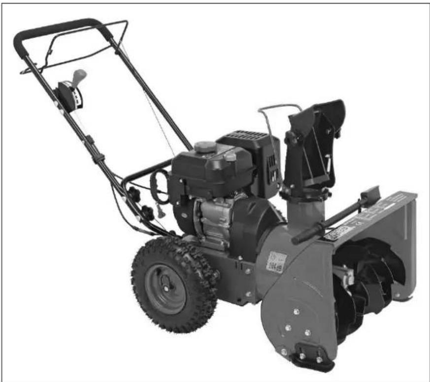
Operating instructions for Snow blower
721-107
natural_image
Black-and-white photo of a snowman with visible blade and shovels (no text or symbols)SV Bruksanvisning i original
NO Bruksanvisning i original
EN Operating instructions in original
SVENSKA 8
SÄKERHETSANVISNINGAR 8
Utbildning 8
Förberedelser....8
Bränslehantering....8
Användning 9
Maintenance and storage 76
Never modify the engine in anyway....77
Symbols 77
TECHNICAL DATA....79
DESCRIPTION 80
Assembly 80
Handle 80
Ejector 81
Setting up 82
Shear screws 82
Cleaning tool 83
Tyre pressure....83
Fuel recommendations 83
Refuelling 83
Oil level inspection 84
Settings 84
Runners 84
Adjusting the runners 85
Ejector unit 85
Rotor lever 85
Drive lever 87
Ignition key 87
Starter cord 87
Rotor 87
Ejector unit 87
Rotor lever 87
Handle, ejector unit 87
Wing nut, ejector unit 87
Scrapper plate....87
Runners 87
Gear lever 88
Forwards 88
Reverse......88
Filler cap 88
Oil filler cap 88
Oil drain plug 88
Choke lever 88
Starting the engine....89
Cord start 89
Power Off 89
Driving 89
Activating the rotor 89
Replacing the shear screws: 90
Maintenance 90
General 90
Engine 90
Tyre pressure....90
Checking the V-belts....90
Scrapper plate and runners 90
Replacing the runners....91
Dismantling the scraper plate 91
Storage 91
Engine preservation....91
Lubrication 91
Rotor shaft 92
Wheels 92
Engine maintenance 92
Maintenance schedule 92
Changing the engine oil 92
Recommended oil....93
Spark plug....93
Cleaning the engine....94
Rotor service....94
Troubleshooting....95
Parts....96
SÄKERHETSANVISNINGAR
Fig. 1 Fig. 2
natural_image
Close-up of a mechanical engine component with visible wiring and mounting brackets (no text or symbols)natural_image
Close-up of a hand adjusting a mechanical component with a white arrow pointing to a specific part (no text or symbols visible)natural_image
Close-up of a hand holding a small object with a circled area, possibly part of a mechanical or electronic component (no visible text or symbols)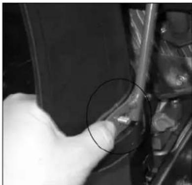
natural_image
Close-up of a hand holding a small object, possibly a tool or device, with no visible text or symbols.natural_image
Close-up of a mechanical component with two circular annotations highlighting features (no readable text or symbols)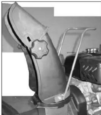
natural_image
Close-up of a mechanical component with a gear-like feature and attached bracket (no visible text or symbols)natural_image
Mechanical assembly diagram showing a lever mechanism with no visible text or symbolsDäcktryck
natural_image
Diagram showing mechanical components with directional arrows, no text or symbols presentUtkastenhet
natural_image
Close-up of a hand using a tool to adjust or install a mechanical component (no visible text or symbols)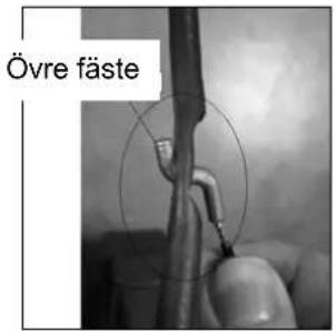
natural_image
Technical line drawing of a mechanical assembly with no visible text or symbolsnatural_image
Technical line drawing of a mechanical assembly with no visible text or symbolsByte av medar
natural_image
Technical line drawing of a mechanical gear or pump assembly (no text or symbols)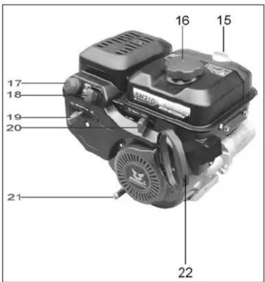
Fig. 1 Fig. 2
natural_image
Close-up of a mechanical engine component with visible wiring and mounting brackets (no text or symbols)natural_image
Close-up of a hand adjusting a mechanical component with a white arrow pointing to a specific part (no text or symbols visible)natural_image
Close-up of a metallic mechanical component with circular annotations and arrows indicating features (no readable text or symbols)natural_image
Close-up of a hand adjusting a mechanical component with a circular annotation (no visible text or symbols)natural_image
Close-up of a hand adjusting a mechanical component with a circular annotation (no visible text or symbols)natural_image
Close-up of a mechanical component with two circular annotations highlighting features (no readable text or symbols)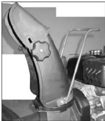
natural_image
Close-up of a leather boot with a star-shaped emblem, mounted on a vehicle (no visible text or symbols)natural_image
Mechanical assembly diagram showing a lever mechanism with no visible text or symbolsDekktrykk
natural_image
Diagram showing a mechanical component with directional arrows indicating movement or force (no text or symbols present)Utkastenhet
natural_image
Close-up of a hand using a tool to adjust or install a mechanical component (no visible text or symbols)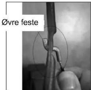
Nedre vaier
natural_image
Technical line drawing of a mechanical component with no visible text or symbolsnatural_image
Technical line drawing of a mechanical assembly with no visible text or symbolsSkifte meier
natural_image
Technical line drawing of a mechanical component with three symmetrical helical structures and central hub (no text or symbols)Rys. 1 Rys. 2
natural_image
Close-up of a mechanical engine component with visible wiring and mounting brackets (no text or symbols)natural_image
Close-up of a hand adjusting a mechanical component with a white arrow pointing to a damaged section (no text or symbols visible)natural_image
Close-up of a hand holding a small mechanical component, possibly a tool or tool, with no visible text or symbols.natural_image
Close-up of a hand pressing a small object on a vehicle (no visible text or symbols)natural_image
Close-up of a metallic mechanical component with two circled features, no visible text or symbols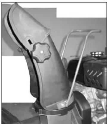
natural_image
Close-up of a mechanical component with a star-shaped knob and metal frame (no visible text or symbols)natural_image
Mechanical assembly diagram showing a lever mechanism with no visible text or symbolsCiśnienie opon
natural_image
Diagram showing a mechanical component with arrows indicating direction, no text or symbols presentnatural_image
Close-up of a hand using a screwdriver to adjust or install a mechanical component (no visible text or symbols)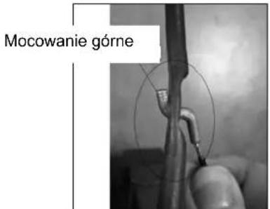
natural_image
Technical line drawing of a mechanical assembly with no visible text or symbolsnatural_image
Technical line drawing of a mechanical assembly with mounting brackets and a housing (no text or symbols)Wymiana płóz
natural_image
Technical line drawing of a mechanical component with symmetrical helical structures and mounting holes (no text or symbols)Read the Operating Instructions carefully before use!

WARNING! This symbol points out important safety instructions that must be observed in order to prevent personal injury and/or damage to property. Failure to follow all the instructions and safety instructions entails a risk of personal injury and/or damage to property.

DANGER! The machine must only be used as described in these instructions. Read all warnings, safety instructions and other directives. Failure to follow all the instructions and safety instructions could result in the risk of serious personal injury and/or death.
Training
- Read all the instructions and all the safety instructions and all the warning labels on the equipment prior to assembly and use. Save these instructions for future reference.
- Familiarise yourself with the controls on the machine and how to use them. Learn how to stop the machine quickly and disengage the drive.
- Do not allow children under 14 to use the machine. The machine may be used by children older than 14 years only if they are under adult supervision.
• Never allow anyone who has not received appropriate instructions to use the machine. - Ejected objects can cause serious personal injury. Plan the work so that materials are not thrown towards roads, bystanders, etc.
- Keep bystanders, especially children and pets, at least 20 metres from the work area. Switch off the machine if anyone enters the work area.
- Be careful to avoid slipping or falling, especially when walking backwards.
Preparations
Carefully inspect the area where the machine is to be used and remove any objects in the way, such as newspapers, planks, stones, cords, mats, sledges, boards, etc.
- Wear safety glasses during use and when making adjustments and/or repairs.
- Wear appropriate winter clothing. Do not wear loose-fitting clothing or jewellery watches or the like, as these can get caught in moving parts. Wear non-slip shoes.
- Machines with electric starter motors may only be connected to an earthed power outlet.
- Adjust the height of the feed hopper so that it is free of gravel and the like.
- Disengage and place all levers in neutral before starting the engine.
• Do not make any adjustments with the engine running, except as stated in this manual.
• Let the engine and machine adjust to the outdoor temperature before you start to clear the snow.
Fuel handling
Be careful when handling fuel – risk of personal injury and/or damage to property. Petrol is highly flammable and can be explosive in certain circumstances. If you get fuel on your skin or clothes, wash immediately.
- Only use an approved fuel container.
- Store and handle petrol away from sparks, naked flames, heat and other ignition sources. Smoking prohibited!
- Never refuel indoors.
- Never remove the fuel cap or add fuel while the engine is running.
- Let the engine cool for at least 2 minutes before refuelling.
- Do not overfill the fuel tank. Do not fill more than 1 cm below the filler pipe, so that the fuel can expand.
- Replace the filler cap and tighten properly.
-
Wipe up any spilled fuel immediately. Move the machine away from the area where you are refuelling. Wait 5 minutes before starting the engine.
-
Never store the machine or fuel container near ignition sources such as a naked flame, water heater, dryer and electric motors that could emit sparks, in order to avoid the risk of ignition of fuel vapours.
- Allow the machine to cool for at least 5 minute before storing.
- Never fill the fuel tank indoors or on a combustible surface. Place the container on the ground at a safe distance from any vehicles.
- If possible move fuel driven machines away from the transport vehicle before refuelling. If refuelling must be done on the transport vehicle, it must be done from a container and not using a fuel pump nozzle.
- Keep the nozzle in contact with the mouth of the fuel tank or the container during the entire refuelling process. Do not block the nozzle in the open position.
Use
- Keep your hands and feet away from moving parts – risk of serious personal injury and/or death.
- The rotor control lever is a safety device that should never be bypassed or disabled as this can lead to a risk of serious personal injury.
- Control levers must be possible to move in both directions and must automatically return to the neutral position when released.
- Never use the machine if the ejector unit is missing or damaged. Safety devices must be fitted correctly and function properly.
- Never start or run the engine indoors or in an enclosed area. Engine exhaust fumes contain carbon monoxide, an odourless and deadly gas.
• Never use the machine when you are tired or under the influence of drugs, alcohol or medication.
• The muffler and engine become hot – risk of burns. Keep children at a safe distance.
• Always be careful when working on or crossing gravel covered entrances, roads, etc.
- Pay attention to traffic and concealed dangers.
- Be very careful when changing direction and on slopes.
- Plan the work so that thrown snow does not hit windows, walls, cars, etc., to avoid the risk of damage to property and/or personal injury.
- Never direct the ejector towards anyone or animals and never let anyone stand in front of the machine.
- Do not overload the machine by trying to remove too much snow too quickly.
- Never use the machine in poor visibility or low light. Make sure you always have a firm footing and hold the handle firmly. Never run with the machine.
• Disengage the rotor drive during transport and when the machine is not in use.
• Never operate the machine quickly on slippery surfaces. Be careful when reversing.
- Stop the engine, remove the spark plug lead and earth this against the engine if the machine starts vibrating abnormally. Check the machine for damage. Repair any damage before the machine is restarted.
- Move all control levers to the neutral position and turn off the engine before leaving the driving position behind the handle. Wait until the rotor has stopped completely before carrying out any inspection or adjustments on the machine or cleaning the ejector.
- Never put your hand in the ejector or intake openings. Always use the accompanying cleaning tool to clear the ejector. Never attempt to clean the ejector when the engine is running. Turn off the engine and remain behind the handle until all moving parts have come to a complete standstill before attempting to clean.
• Only use parts and accessories that are recommended by the manufacturer.
- To start the engine, pull the starter cord slowly until it catches and then pull quickly. Hold the handle firmly and allow it to return slowly to its original position, otherwise there is a risk that it returns so quickly that the hand is drawn towards the engine - a risk of personal injury.
- Contact your dealer if you have any questions.
Maintenance and storage
- Never modify the safety devices in any way. Regularly check that all safety devices are in place and are functioning properly according to these instructions.
- Move all control levers to the neutral position, turn off the engine and wait until all moving parts have stopped completely before cleaning or carrying out checks and/or repairs. Loosen the spark plug lead and earth this against the engine to prevent unintentional starting.
-
Check all bolted joints regularly, and retighten if necessary. Regularly check the machine visually for damage.
-
Do not change the speed governor setting and do not overspeed the engine. The speed governor controls maximum permitted engine speed.
- Glide plates and runners wear and are subjected to damage. Regularly check all components and replace if necessary using original spare parts recommended by the manufacturer. The use of other spare parts can cause malfunctioning, damage to property and/or personal injury.
- Regularly check that all the control levers can be moved correctly and automatically return to the neutral position when released. Adjust, if necessary, according to these instructions.
- Stickers bearing safety information and instructions must always be clean and legible. Replace the stickers if necessary.
- Observe applicable laws and regulations relating to fuel, oil, etc.
- Before putting the machine away for storage, let it run for several minutes to clear any snow so that the rotor does not freeze solid.
- Never store the machine or fuel container near ignition sources such as a naked flame, water heater, dryer and electric motors that could emit sparks, in order to avoid the risk of ignition of fuel vapours.
- Follow the instructions for storage.
- Check fuel lines, the tank, fuel filler cap and fittings frequently for cracks or leaks. Replace them if necessary.
- Do not turnover the engine when the spark plug is not fitted.
- The machine must be inspected at an authorised service centre at least once a year, to avoid the risk of damage to property, personal injury and/or death.
Never modify the engine in anyway.
Never modify the engine in anyway – risk of serious personal injury and/or death. Never change the factory setting on the speed governor, this can cause the engine to overspeed and result in a risk of personal injury or damage to property.
Symbols
The following symbols may appear on the warning label on the machine. Read all the instructions and all the safety instructions and all the warning labels on the machine prior to assembly and use.
| Symbol | Explanation |
 | Read these instructions carefully.Read these instructions carefully before assembly and use. |
 | Wear ear protection. |
 | Wear safety glasses. |
 | WARNING Rotating parts.Keep your hands and feet away from moving parts – risk of serious personal injury and/or death. |
 | WARNING Rotating blades.Keep your hands and feet away from openings when the machine is in operation. |
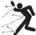 | WARNING Objects can be thrown.Ejected objects can cause serious personal injury. |
 | Wait until all moving parts have come to a complete standstill before touching them. |
 | |
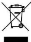 | When the product is worn out, it must be disposed of in accordance with the applicable regulations. |
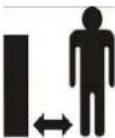 | Keep children at least 10 metres from the work area. |
 | WARNING Petrol is highly flammable.Allow the engine to cool for at least 2 minutes before refuelling. |
 | WARNING Carbon monoxide.Never start or run the engine indoors or in an enclosed area.Engine exhaust fumes contain carbon monoxide, an odourless and deadly gas. |
 | WARNING Electrical hazards (only engines with electric start)Do not use the electric start in the rain or in damp areas. |

WARNING! Never permit anyone who has not read all the instructions and all the safety instructions and all the warning labels on the machine to use the machine. SAVE THESE INSTRUCTIONS FOR FUTURE REFERENCE.
TECHNICAL DATA
| Working width 510 mm | ||
| Working height 400 mm | ||
| 4 forward gears, 2 reverse gears | ||
| Output | 4.0 | kW |
| Speed (no load) 3600 rpm | ||
| Starting system Manual start | ||
| Fuel tank capacity 2.5 l | ||
| Oil reservoir volume 0.5 l | ||
| Measured sound power level, LwA 103,6 dB(A) | ||
| Guaranteed sound power level, LwA 105 dB(A) | ||
| Sound pressure level, LpA 88 dB(A), K=1,5 dB | ||
| Vibration level 8 m/s | ^2 , K=1,5 m/s ^2 | |
Always wear ear protection!
The declared vibration value, which has been measured by a standardised test method, can be used to compare different tools with each other and for a preliminary assessment of exposure.
WARNING! The actual vibration level when using power tools may differ from the specified maximum value, depending on how the tool is used. It is therefore necessary to determine which safety precautions are required to protect the user, based on an estimate of exposure in actual operating conditions (taking into account all stages of the work cycle, e.g. the time when the tool is switched off and when it is idling, in addition to the start-up time).
DESCRIPTION
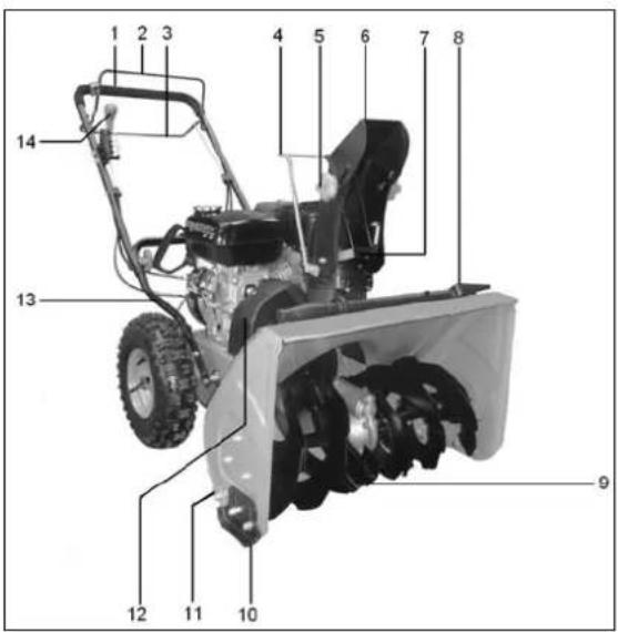
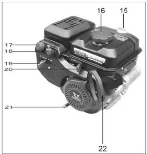
Fig. 1 Fig. 2
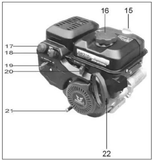
- Upper handle
- Rotor lever
- Drive lever
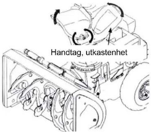
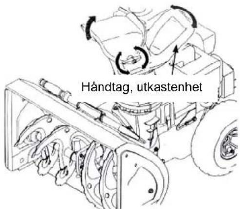
- Handle, ejector unit
- Wing nut, ejector unit
- Upper ejector
- Safety bracket
- Cleaning tool
- Rotor
- Runner
- Scrapper plate
- Belt cover
-
Lower handle
-
Gear lever
- Oil filler cap
- Filler cap
- Fuel primer bulb.
- Ignition key
- Choke
- Throttle lever
- Oil drain lug
- Starter cord handle
ASSEMBLY
Handle
natural_image
Close-up of a mechanical device with visible wiring and mounting brackets (no text or symbols)- Remove any protective plastic from the handles.
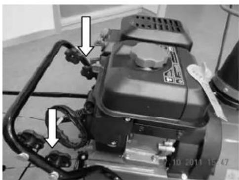
- Remove the wing nut, washer and screw on each side of the lower handle.
natural_image
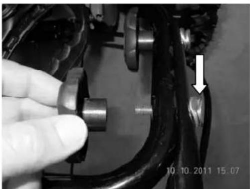
Close-up of a hand adjusting a mechanical component with a white arrow pointing to a detail (no text or symbols visible)- Place the upper handle over the lower, with the holes aligned.
IMPORTANT! Be careful not to bend or fold the wires
-
Insert the screw from the outside, through the upper and lower handles and the washer, and screw on the wing nut. Repeat on the other side.
-
Tighten the wing nuts on either side of the handle.
Ejector
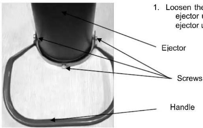
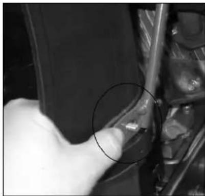
- Loosen the three screws and nuts from the ejector unit and remove the handle from the ejector unit.
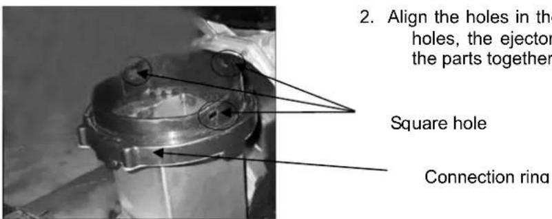
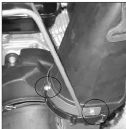
- Align the holes in the ring with three square holes, the ejector unit and handle and hold the parts together.
natural_image
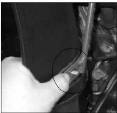
Close-up of a hand pointing to a small object on a vehicle wheel (no visible text or symbols)- Insert a screw through one of the holes and secure with one of the nuts.
natural_image
Close-up of a hand pointing to a small mechanical component with a circled area (no visible text or symbols)- Repeat for the other two holes.
natural_image
Close-up of a mechanical component with two circled features, no visible text or symbols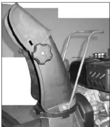
natural_image
Close-up of a leather shoe with a star-shaped emblem, mounted on a metal frame (no visible text or symbols)- Try turning the ejector unit with the handle
SETTING UP
Shear screws
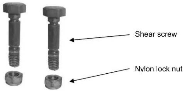
2 extra shear screws and nylon lock nuts are supplied. Keep them in a safe place until they are needed.
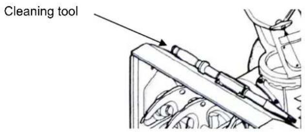
Cleaning tool
The cleaning tool is attached on top of the rotor housing at the factory with a clip and a cable tie. Cut the cable tie before use.
Tyre pressure
The correct tyre pressure is 1–1.4 bar. Regularly check the tyre pressure and correct if necessary. Both tyres must have the same pressure. Do not over inflate the tyres. Too high pressure can cause the wheel to explode - the risk of serious personal injury.
WARNING! Do not use a compressor.
Fuel recommendations
Use unleaded petrol with a rating of at least 87 octane. Petrol with at most 10% ethanol or 15% MTBE (methyl tertiary butyl ether) can be used. Never use old, contaminated fuel or fuel mixed with oil. Avoid getting water and debris in the fuel tank. Do not use E85.
- Only refuel in a well-ventilated area with the engine switched off. Keep petrol away from sparks and naked flames, and do not smoke where petrol is stored or when filling petrol.
• Do not overfill the tank. Replace the filler cap properly after filling. - Be careful not to spill fuel when filling. Spilled fuel and fuel fumes constitute a fire risk. Wipe up any spilled fuel before starting the engine.
- Avoid repeated or prolonged skin contact with fuel and/or inhalation of fuel fumes.
Refuelling

WARNING! Be very careful when handling fuel. Petrol is highly flammable and can be explosive in certain circumstances. Never refuel indoors or with the engine running. Store and handle petrol away from sparks, naked flames, heat and other ignition sources. Smoking prohibited!

WARNING! Keep your hands and feet away from moving parts. Do not use starting fluid. Vapours are highly flammable.
- Clean the area around the filler cap before opening the fuel cap.
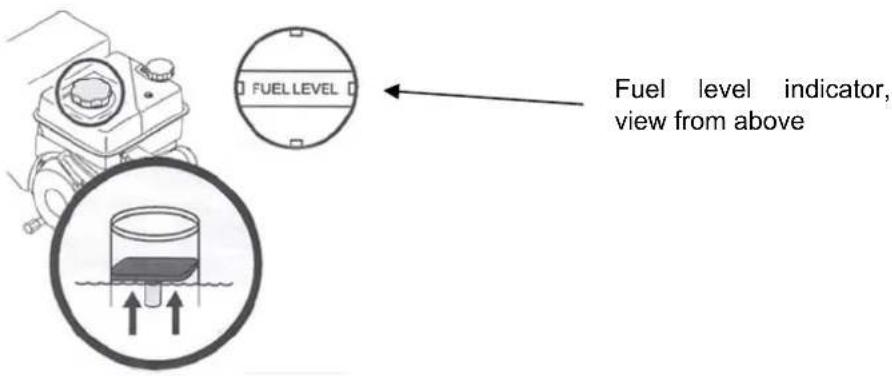
- The fuel tank has a level indicator. Fill up to the red plate in the screen. Do not overfill.
Oil level inspection

IMPORTANT! The engine is supplied without oil. Fill with oil and check the oil level prior to starting the engine. Do not run the engine with insufficient oil – risk of serious engine damage. The warranty does not cover damage resulting from the engine being run with too little oil.
NOTE! Check the engine's oil level on a flat surface with the engine turned off.
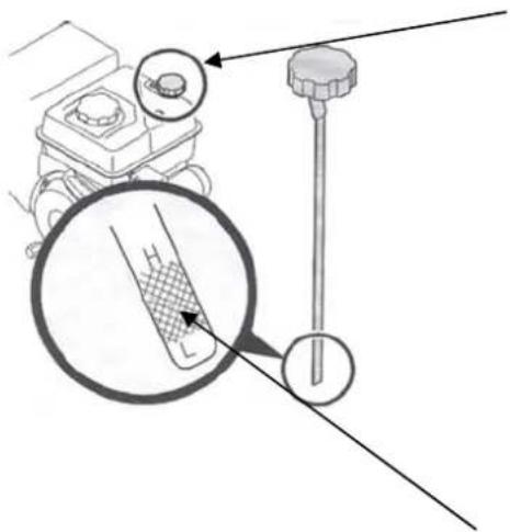
- Remove the oil filler cap and the dipstick and wipe the dipstick.
- Refit the filler cap with the dipstick without tightening.
- Remove the oil filler cap with the dipstick again. Top up the oil if the level is too low. The correct viscosity and oil volume are set out in the engine maintenance section.
NOTE! Do not overfill. This can cause the engine to smoke, be difficult to start or cause soot on the spark plug.
- Refit the filler cap with the dipstick and tighten before starting the engine.
NOTE! Fill so that the level is between the minimum and maximum markings.
SETTINGS
Runners
The runners on the snow blower are mounted in the highest position during transport. Move them down, if necessary, before use.

IMPORTANT! We recommend that you do not run the snow blower on gravel, it can throw stones that can cause personal injury or damage to property. If, however, you need to drive on a gravel surface, place the runners at the lowest position for the maximum amount of clearance.
- Move the runners further up on the rotor housing for a thinner level of remaining snow cover.
- Place the runners in the centre position or lower when working on uneven ground.
Adjusting the runners
natural_image
Diagram showing a mechanical component with directional arrows indicating movement or force (no text or symbols present)-
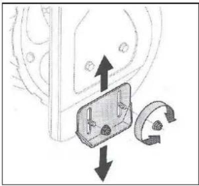
Loosen the four hexagonal nuts (two on each side) and the screws. Move the runners to the position required.
-
Make sure that the underside of the runners rests on the ground along the whole of their length, to avoid the runners wearing unevenly.
-
Make sure the screw unions are properly tightened.
Ejector unit
-
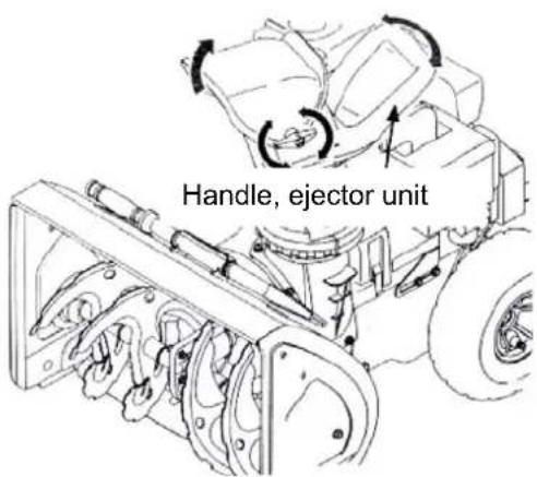
Loosen the wing nut on top of the unit and turn the ejector unit to the position required.
-
Tighten the wing nut.
Rotor lever
The rotor lever wire must be checked regularly and adjusted if necessary, due to normal wear and that the belt stretches. Adjust immediately if any of the following occurs.
- Rotation continues even though the rotor lever is disengaged.
• The rotor gets caught during operation, even though the engine speed remains constant.
NOTE! Make the following checks before the machine is used for the first time and before it is put into operation when the season starts. Check the rotor lever as instructed below.
- When you release the rotor lever in the disengaged, upper position there should be very little play on the wire, but it must not be tight.
- Start the engine in a well-ventilated area, as instructed in the section about use. Set the throttle lever in the high revs position.
- Stand in the driving position behind the handle and engage the rotor.
- Let the rotor remain engaged for about 10 seconds and then release the rotor lever. Repeat several times.
- Let the engine run with the throttle lever in the high revs position and the rotor lever disengaged. Go round to the front of the machine.
- Make sure that the rotor has come to a complete standstill and does not move at all.
NOTE! If the rotor moves at all, go back to the driving position immediately and stop the engine. Wait until all moving parts have come to a complete standstill and adjust the rotor wire as instructed below.
natural_image
Close-up of a hand holding a tool interacting with a car engine component (no visible text or symbols)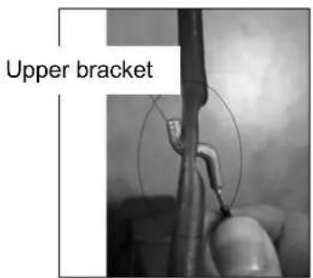
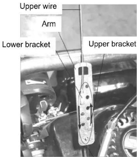
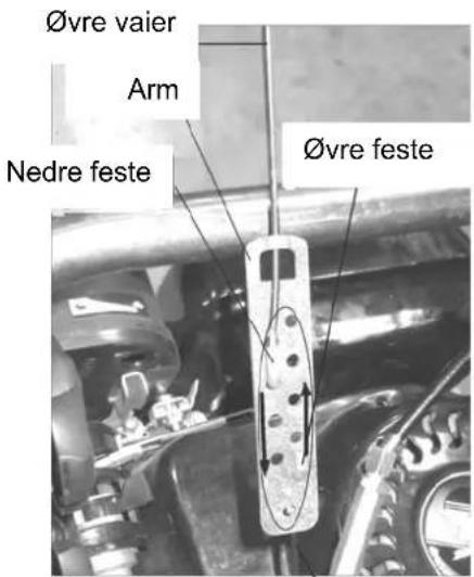
Lower wire
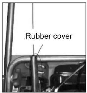
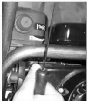
- Tip up the machine. Hold the cover firmly with one hand. Loosen the upper wire's upper bracket with the other hand.
- Remove the rubber cover, loosen the upper wire's lower bracket and insert it in the lower hole in the arm to tighten the wire. You can also loosen the lower wire's upper bracket and insert it in the upper hole in the arm to tighten the wire. Test drive. If the machine runs correctly refit the rubber cover.
- Start the engine and check that the rotor engages and disengages correctly.
NOTE! Turn off the engine and adjust again if the rotor continues to rotate when the lever is disengaged.
- If the rotor appears to get stuck even though the engine runs at a constant speed, the cable is too slack. Follow the instructions above to tighten the wire.

WARNING! Do not tighten the wire too tight, this can cause the rotor not to disengage properly, resulting in a risk of personal injury or damage to property.
Drive lever
The drive lever, which is positioned on the upper handle's underside, connects and disconnects wheel drive. Press the drive lever towards the handle to engage the drive, then release to disengage.
Ignition key
The ignition key is a safety device. It must be fully inserted in order to start the engine. Remove the ignition key when the machine is not in use.
NOTE! Do not turn the ignition key, it may break.
Starter cord
The starter cord is used to start the engine.
Rotor
When the rotor is engaged it feeds snow into the rotor housing and throws it out through the ejector.
Ejector unit
The snow the rotor feeds into the rotor housing is thrown out through the ejector unit.
Rotor lever
The rotor lever is positioned on the upper handle. Press the rotor lever towards the handle to engage the rotor, then release to disengage.
WARNING! Never carry out any adjustments on the ejector unit unless both the rotor and drive levers are in the disengaged position and you are standing next to the machine.
IMPORTANT! Adjust the rotor lever according to these instructions before use, otherwise there is a risk of personal injury and/or damage to property.
Handle, ejector unit
The ejector unit can be set in the required ejection direction by using the handle.
Wing nut, ejector unit
Set how far the snow is thrown by raising or lowering the top of the ejector unit. Loosen the wing nut, move the upper part to the position required and tighten the wing nut.
Scrapper plate
The scraper plate rests against the surface during operations to permit snow removal to a shallow depth.
Runners
Place the runners at the appropriate height, higher up for hard packed snow, lower down when driving on gravel.
Gear lever
The gear lever (see fig. 1-14) sits on the right-hand side of the handle. It has 6 positions for driving forwards and reversing at different speeds.
Forwards
The machine has 4 forward gears (F), where 1st is the slowest. Drive at the lowest speed when snow throwing.
Reverse
The machine has 2 reverse gears (R), where 1st is the slowest.
IMPORTANT! Always release the drive lever before shifting gears.
Filler cap
Unscrew the filler cap before refuelling. The machine is powered by ordinary petrol.
Oil filler cap
Check and top up the oil when necessary through the oil filler cap.
NOTE! The engine is supplied without oil. Fill with oil and check the oil level before starting the engine and top up, if necessary. Check the oil level before each use.
Oil drain plug
Used to drain the oil.
Choke lever
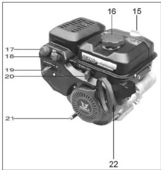
The choke lever is located at the rear of the engine (see fig.2-19). Move the arm to the left to close the
choke valve and facilitate starting
Fuel primer bulb.
Press the primer bulb (see fig.2-17) to pump fuel into the carburettor to facilitate cold start

Throttle lever
The throttle lever is located at the rear of the engine (see fig. 1-20). It controls the engine speed and stops the engine when placed in the STOP position.
Starter cord handle
Used to start the engine manually.
Ejector unit
The snow the rotor feeds into the rotor housing is thrown out through the ejector unit.
Cleaning tool

WARNING! Never clean the ejector unit with your hands. Turn off the engine and remain behind handle until all moving parts have come to a complete standstill before attempting to clean.
The cleaning sits in a clip at the rear of the rotor housing. Follow the instructions below to clear snow that had become compacted in the ejector unit
- Disengage the rotor and drive levers.
- Turn off the engine by removing the ignition key.
- Remove the cleaning tool from the clip at the rear of the rotor housing.
- Clear the snow and ice with the spade-shaped end of the cleaning tool.
- Return the cleaning tool in the clip on the rotor housing, insert the ignition key and start the engine.
Stand in the driving position behind the handle and engage the rotor lever for a few seconds to throw out any snow and ice remaining in the ejector unit.
USE
Starting the engine.

WARNING! Keep your hands and feet away from moving parts. Do not use starting fluid. Vapours hly flammable.
NOTE! Let the engine run for a few minutes. The engine does not produce full output until it reaches operating temperature.
Cord start

IMPORTANT! Do not pull the starter cord handle when the engine is running.

WARNING! Do not leave the machine unattended with the engine running. Switch off the engine move the ignition key before leaving the machine.
- Insert the ignition key completely. Do NOT turn the ignition key. The engine cannot be started if the ignition key is not inserted.
- Move the throttle lever to the high revs position.
- Close the choke if the engine is cold. Open the choke if the engine is warm.
- If the engine is cold, block the ventilation hole and press the primer bulb 3-5 times. If the engine is warm, block the ventilation hole and press once. If it is cold you may need to press the primer bulb again.
- Pull the starter cord slowly until it catches and then pull quickly. Do not release handle, but move it back slowly to its original position. Repeat, if necessary.
- Slowly move the choke to open position when the engine becomes warm. If the engine stops, start it again and let it run for a short time with the choke half-open before you slowly move the choke to open position.
Power Off

WARNING! Do not leave the machine unattended with the engine running. Switch off the engine se and remove the ignition key. Allow the engine to run without a load for a few minutes before g it to remove any moisture.
- Move the throttle lever to the STOP position.
- Remove the ignition key to prevent accidental or unauthorised starting. Keep the key in a safe place. The engine cannot be started without the ignition key.
- Wipe all controls on the engine dry.
Driving
- Move the throttle lever to the high revs position.
- Activate driving by pressing the drive lever fully against the upper handle. Release the drive lever to stop.
Activating the rotor
Activate the rotor by pressing the rotor lever fully against the upper handle. Release the rotor lever to stop the rotor.
Replacing the shear screws:
natural_image
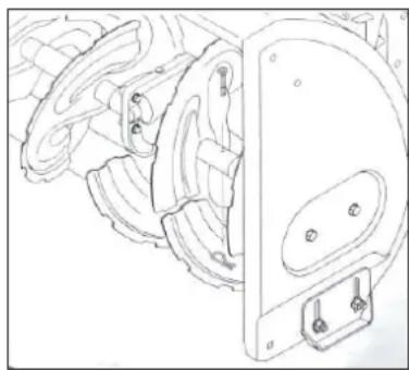
Technical line drawing of a mechanical assembly with no visible text or symbolsThe rotor is mounted on the spiral shaft with two shear screws with nylon nuts. The shear screws can shear off if the rotor hits ice or a solid object. If the rotor does not rotate, check whether the shear screws have sheared off.
IMPORTANT! Never replace the shear screws with anything else other than identical shear screws from the manufacturer. Any damage incurred if other components are used is not covered by the warranty.
WARNING! Switch off the machine and remove the ignition key before replacing the shear screws.
MAINTENANCE
General
• Always follow the safety instructions during maintenance work.
- Regularly check that all bolted joints are tightened correctly.

WARNING! Turn off the engine and disconnect all the levers before servicing, making repairs, lubrication and/or inspection. Wait until all moving parts have come to a complete standstill. Loosen the spark plug lead and earth this against the engine to prevent unintentional starting. Always wear safety glasses when working with or on the machine.
Engine
The following are general guidelines for engine maintenance. More detailed instructions can be found in the engine maintenance section.
- Check the oil level before each use.
- Change the engine oil after 5 hours of operation and then every 25 hours of operation.
- Clean the spark plug and adjust electrode gap to 0.76 mm at least once every season or after 100 hours of operation. Replace the spark plug at intervals of 200 hours of operation.
Tyre pressure
Check and adjust if necessary, the tyre pressure before each use. The tyre pressure should be 1–1.4 bar. If both tyres do have the same pressure, the machine may pull to one side.
Checking the V-belts
Check the condition of the drive belts as set out below at intervals of 50 hours of operation.
- Remove the plastic cover over the belt on the front of the engine, loosen the screws and press the plastic tabs.
- Check the belts for wear, cracks and fraying. Replace if necessary.
Scrapper plate and runners
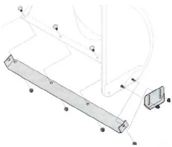
The scraper plate and runners wear and must be checked regularly and replaced if necessary.
natural_image
Technical line drawing of a mechanical assembly with no visible text or symbolsReplacing the runners
- Loosen the screws and nuts holding the runners by the rotor housing.
NOTE! For reasons of clarity the rotor is not shown in the picture.
- Fit the new runners with screws and nuts. The runners must sit at the same height.
Dismantling the scraper plate
- Dismantle the runners and the screws and nuts holding the scraper plate by the machine casing.
- Fit the new scraper plate with all bolt heads on the inside of the casing.
- Refit the runners and tighten all the bolt joints properly.
Storage
Follow the instructions below if the machine will not be used for at least 30 days.
- Store in a clean, dry place.
- Clean the machine and its engine on the outside.
- If the machine is kept in an unventilated area it must be corrosion protected with a thin layer of thin-bodied oil
Engine preservation

WARNING! Never store the machine or fuel container near ignition sources such as a naked
flame, water heater, dryer and electric motors that could emit sparks, in order to avoid the risk of ignition of fuel vapours.
NOTE! If the engine is not to be used for at least 30 days, the fuel system should be drained to prevent deposits forming in the fuel system.
IMPORTANT! Ethanol or methanol blended fuels may attract water, which can lead to separation and the formation of acids during storage, which can damage the fuel system.
The fuel system should be drained if the machine will not be used for at least 30 days in order to avoid engine problems. Follow the instructions below if the machine will not be used for at least 30 days.

WARNING! Let the engine cool and drain the fuel into a suitable container. Work outside, away from ignition sources. Do not smoke. The fuel that remains in the engine in hot weather is broken down and can cause serious starting problems.
- Run the engine until the fuel tank is empty and the engine stops due to a shortage of fuel.
- Change the engine oil.
- Remove the spark plug and pour two tablespoons of engine oil into the cylinder through the spark plug hole. Cover the spark plug hole with a cloth and turn over the engine by pulling the starter cord several times to distribute the oil. Replace the spark plug.
- Clean the engine and the area around the muffler. Apply a thin film of oil on corrosion-prone areas.
Lubrication
Lubricate the pivot points on the rotor and drive levers using thin-bodied engine oil every season.
Rotor shaft
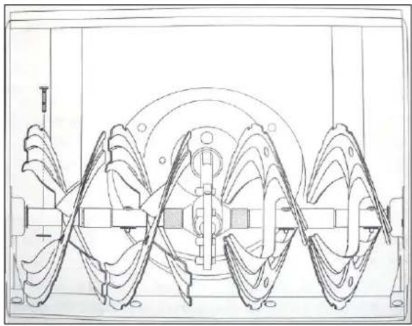
natural_image
Technical line drawing of a mechanical pump or turbine assembly (no text or symbols)The shear screws should be dismantled from the rotor shaft at least once a season and a suitable lubricant is sprayed on the shaft around the spacers and around flange bearings on the ends of the shaft.
Wheels
Both wheels should be dismantled at least once a season. Clean the axles and apply automotive grease. Refit the wheels.
Engine maintenance

WARNING! Switch off the engine and remove the ignition key before starting maintenance.
Perform maintenance according to the table below. In demanding conditions, maintenance should be carried out at shorter intervals.
Maintenance schedule
| Action | After hours | Before 5 each use and at intervals of 5 hours of operation | Each season or at intervals of 25 hours of operation. | Each season or at intervals of 50 hours of operation. | Each season or at intervals of 100 hours of operation. | Service date |
| Check the engine oil | • | |||||
| Changing the engine oil | • | • | ||||
| Check the spark plug | • | |||||
| Spark plug | • | service | • | |||
| Clean the exhaust area | • |
Changing the engine oil
NOTE! Check the oil level before each use and at intervals of 5 hours of operation. Top up if necessary.
-
Drain the fuel tank by running the engine until the fuel tank is empty. Check that the filler cap is properly tightened.
-
Place a suitable container under the drain plug.
-
Remove the oil drain plug (fig.2-21).
-
Tilt the engine to pour oil into the container. Used oil must be disposed of in accordance with local regulations.
-
Replace the drain plug and tighten firmly.
-
Fill using oil of the recommended grade to the indicated level.
-
Put the oil filler cap back with dipstick.

IMPORTANT! Wash your hands immediately with soap and water after handling oil.
NOTE! Used oil must be disposed of in accordance with applicable regulations.
Recommended oil
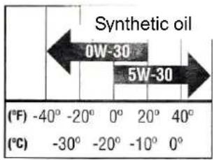
Use oil according to the table. The engine oil volume is 0.5 l. Do not overfill. Use good grade 4-stroke engine oil.

IMPORTANT! Do not use another oil grade than those recommended by the manufacturer, it can be an engine life.
Spark plug

WARNING! Do not check the spark with spark plug removed. Do not turnover the engine when
the spark plug is not fitted.

WARNING! The muffler is hot when the engine has been running – risk of burns.
For good engine performance, the spark plug must be clean and have the right spark clearance.
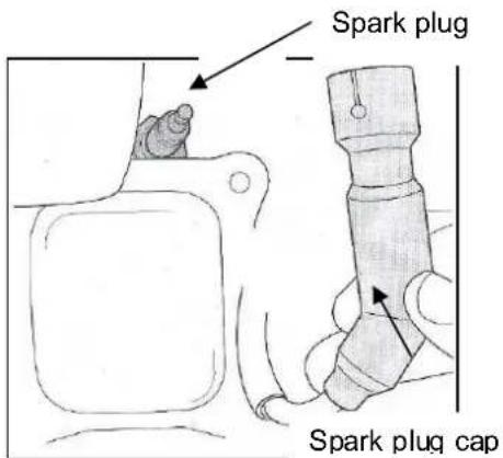
-
Remove the spark plug cap and unscrew the spark plug using a spark plug spanner.
-
Inspect the spark plug. Discard the spark plug if it is visibly worn or if the insulator is cracked or broken. Clean the spark plug with a steel brush if it is to be used again.
Electrode
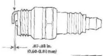
-
Measure the electrode gap with a feeler gauge. Correct the gap, if necessary, by gently bending the electrode. The gap should be 0.60 to 0.80 mm.
-
Check that the sealing washer is in good condition. Unscrew the spark plug carefully by hand to avoid threading problems.
- Tighten the spark plug with a suitable spanner to compress the sealing washer.
NOTE! Tighten a new spark plug a 1/2 turn after it seats to compress the sealing washer. If refitting the same, used spark plug, tighten it 1/8–1/4 turn after it seats to compress the sealing washer.

IMPORTANT! Tighten the spark plug correctly. A loose spark plug can overheat and damage the engine.
Cleaning the engine.
If the engine has been running, leave it to cool for at least 30 minutes before cleaning. Regularly remove debris that has accumulated on the engine.

IMPORTANT! Do not spray water on the engine - risk of fuel contamination or water entering the muffler opening.

WARNING! Clean out accumulated debris from the muffler before use - fire hazard.
Rotor service
The rotors are mounted on the spiral shaft with two shear screws with nylon nuts. The shear screws can shear off if the rotor hits ice or a solid object.
If the rotor does not rotate, check whether the shear screws have sheared off. Replace the shear screws with identical shear screws from the manufacturer.
IMPORTANT! Never replace the shear screws with anything else other than identical shear screws from the manufacturer. Any damage incurred if other components are used is not covered by the warranty.
TROUBLESHOOTING
| Problem Cause Action | ||
| The motor will not start | Empty fuel tank, or old fuel.Blocked fuel line.Ignition key not inserted correctly.Loose ignition cable.Defective spark plug.Engine flooded.Throttle lever in stop position. | Fill the tank with fresh petrol.Clear the fuel line.Insert the ignition key correctly.Fit the spark plug cap on the spark plug.Clean the spark plug. Adjust the spark gap or replace the spark plug.Pump four times on the primer bulb.Wait at least 10 minutes before attempting to start.Move the throttle lever to the high revs position. |
| The engine does not run smoothly | The choke is closed.Blocked fuel line or old fuel. | Move the choke to fully open position.Clean the fuel line and fill the tank with fresh petrol. |
| Low power. | Spark plug lead is loose.Ventilation hole in filler cap clogged. | Refit the spark plug lead.Clear the ventilation hole. |
| Heavy vibration | Loose parts or damaged rotor. | Switch off the engine immediately and remove the ignition key. Check with regard to damage. Tighten all the screw unions. Repair if necessary. Contact an authorised service centre if the problem persists. |
| Forward drive does not work | Loose or damaged drive belt. | Replace the belt. |
| The rotor does not stop | Wire adjusted incorrectly. | Adjusted the rotor lever wire. |
| The machine does not throw snow | Ejector unit blocked.One or more shear screws have sheared off.Foreign object blocking the rotor.Rotor lever wire adjusted incorrectly.Rotor drive belt loose or damaged. | Switch off the engine immediately and remove the ignition key. Clear the ejector unit using the cleaning tool or a stick.Replace the shear screws.Switch off the engine immediately and remove the ignition key. Remove the foreign object from the rotor.Adjusted the rotor lever wire.Replace the belt. |
Parts
| Part | Description |
 | Cleaning tool |
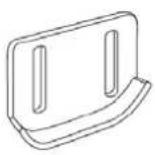 | Runner, standard |
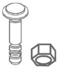 | Shear screwNylon lock nut |
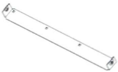 | Scrapper plate |
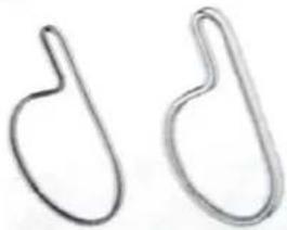 | Drive belt, rotorDrive belt, wheels |
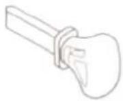 | Ignition key |
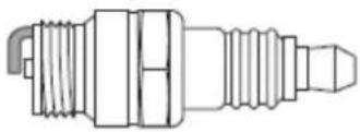 | Spark plug |
Subject to printing errors and design changes over which we have no control. In the event of problems, please contact our service department.
www.jula.com
Care for the environment!
Must not be discarded with household waste!
This product contains electrical or electronic components that should be recycled.
Leave the product for recycling at the designated station e.g. the local authority's recycling station.
CE
EC DECLARATION OF CONFORMITY
EG FÖRSÄKRAN OM ÖVERENSSTÄMMELSE
EF SAMSVARSERKLÆRING
DEKLARACJA ZGODNOŚCI WE

Jula AB, Box 363, SE-532 24 SKARA, SWEDEN
Machinery Directive 2006/42/EC,
Electromagnetic Compatibility 2004/108/EC,
Outdoor Noise Directive 2000/14/EC, amended by 2005/88/EC
EN 60335-1:2002+A11+A1+A12+A2+A13+A14,
ISO/DIS 8437:2008, EN ISO 14982:2009
This product was CE marked in year -11
Name and address of the person
authorised to compile the technical file:
Erik Svedén
Box 363, SE-532 37 Skara, Sweden
Skara 2011-08-04
natural_image
Abstract line drawing with intersecting curves and a horizontal line (no text or symbols)Stefan Rundberg
PRODUCT MANAGER
- Operating instructions for Snow blower
- SVENSKA 8
- SÄKERHETSANVISNINGAR 8
- Assembly 80
- Setting up 82
- Settings 84
- Maintenance 90
- SÄKERHETSANVISNINGAR
- Däcktryck
- Utkastenhet
- Byte av medar
- Dekktrykk
- Skifte meier
- Ciśnienie opon
- Wymiana płóz
- Read the Operating Instructions carefully before use!
- Training
- Preparations
- Fuel handling
- Use
- Maintenance and storage
- Never modify the engine in anyway.
- Symbols
- Always wear ear protection!
- DESCRIPTION
- ASSEMBLY
- Handle
- Ejector
- SETTING UP
- Shear screws
- Cleaning tool
- Tyre pressure
- Fuel recommendations
- Refuelling
- Oil level inspection
- SETTINGS
- Runners
- Adjusting the runners
- Ejector unit
- Rotor lever
- Drive lever
- Ignition key
- Starter cord
- Rotor
- Handle, ejector unit
- Wing nut, ejector unit
- Scrapper plate
- Gear lever
- Forwards
- Reverse
- Filler cap
- Oil filler cap
- Oil drain plug
- Choke lever
- Fuel primer bulb.
- Throttle lever
- Starter cord handle
- Starting the engine.
- Cord start
- Power Off
- Driving
- Activating the rotor
- Replacing the shear screws:
- MAINTENANCE
- General
- Engine
- Checking the V-belts
- Scrapper plate and runners
- Replacing the runners
- Dismantling the scraper plate
- Storage
- Engine preservation
- Lubrication
- Rotor shaft
- Wheels
- Engine maintenance
- Maintenance schedule
- Changing the engine oil
- Recommended oil
- Spark plug
- Cleaning the engine.
- Rotor service
- Care for the environment!
- CE
- EC DECLARATION OF CONFORMITY
- EG FÖRSÄKRAN OM ÖVERENSSTÄMMELSE
- EF SAMSVARSERKLÆRING
- DEKLARACJA ZGODNOŚCI WE
Brand : Meec Tools
Model : 721-107
Category : Lance-pierre