
FDF 6146 XS ECS - Range hood FRANKE - Free user manual and instructions
Find the device manual for free FDF 6146 XS ECS FRANKE in PDF.


| Product Type | Cooker Hood |
| Brand | Franke |
| Model | FDF 6146 XS ECS |
| Installation Type | Wall-mounted telescopic chimney |
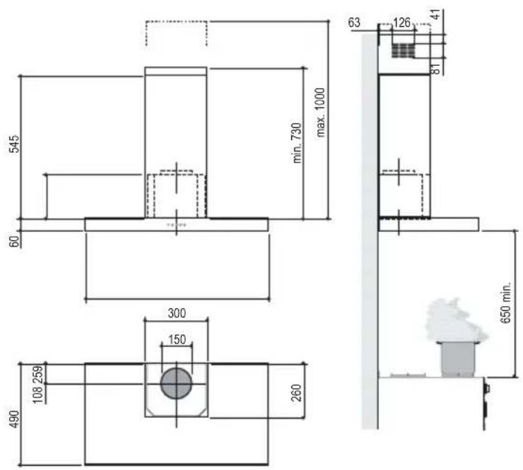
| Dimensions (Width x Depth) | 545 mm x 490 mm |
| Height Range | 730 mm to 1000 mm (adjustable) |
| Minimum Distance from Hob | 650 mm |
| Exhaust Connection Diameter | 150 mm (120 mm with reducer) |
| Air Extraction Type | Ducted or recirculation (with charcoal filter) |
| Motor Speed Settings | 3 speeds (Low, Medium, Intensive) |
| Controls | Push buttons with LED indicator |
| Lighting | 1 x 40W incandescent (replaceable) |
| Grease Filter Type | Metal self-supporting, washable in dishwasher |
| Charcoal Filter (Optional) | Activated carbon, non-washable, replace every 4 months |
| Easy Cleaning System | Removable suction unit for fan cleaning |
| Electrical Rating | 220-240 V, 50/60 Hz |
| Energy Class (if available) | Not specified |
| Noise Level | Not specified |
| Materials | Stainless steel |
Frequently Asked Questions - FDF 6146 XS ECS FRANKE
User questions about FDF 6146 XS ECS FRANKE
0 question about this device. Answer the ones you know or ask your own.
Ask a new question about this device
Download the instructions for your Range hood in PDF format for free! Find your manual FDF 6146 XS ECS - FRANKE and take your electronic device back in hand. On this page are published all the documents necessary for the use of your device. FDF 6146 XS ECS by FRANKE.
USER MANUAL FDF 6146 XS ECS FRANKE
Instructions for use and installation
Cooker Hood

Instructions Manual INDEX
RECOMMENDATIONS AND SUGGESTIONS....7
CHARACTERISTICS 8
INSTALLATION 9
USE....12
MAINTENANCE....13
EASY CLEANING TM 14
RECOMMENDATIONS AND SUGGESTIONS
INSTALLATION
- The manufacturer will not be held liable for any damages resulting from incorrect or improper installation.
- The minimum safety distance between the cooker top and the extractor hood is 650 mm.
- Check that the mains voltage corresponds to that indicated on the rating plate fixed to the inside of the hood.
- For Class I appliances, check that the domestic power supply guarantees adequate earthing.
Connect the extractor to the exhaust flue through a pipe of minimum diameter 120 mm. The route of the flue must be as short as possible.
- Do not connect the extractor hood to exhaust ducts carrying combustion fumes (boilers, fireplaces, etc.).
- If the extractor is used in conjunction with non-electrical appliances (e.g. gas burning appliances), a sufficient degree of aeration must be guaranteed in the room in order to prevent the backflow of exhaust gas. The kitchen must have an opening communicating directly with the open air in order to guarantee the entry of clean air.
USE
- The extractor hood has been designed exclusively for domestic use to eliminate kitchen smells.
- Never use the hood for purposes other than for which it has been designed.
- Never leave high naked flames under the hood when it is in operation.
- Adjust the flame intensity to direct it onto the bottom of the pan only, making sure that it does not engulf the sides.
- Deep fat fryers must be continuously monitored during use: overheated oil can burst into flames.
- Do not flambè under the range hood; risk of fire
- The hood should not be used by children or persons not instructed in its correct use.
MAINTENANCE
- Switch off or unplug the appliance from the mains supply before carrying out any maintenance work.
- Clean and/or replace the Filters after the specified time period.
- Clean the hood using a damp cloth and a neutral liquid detergent.


Dimensions
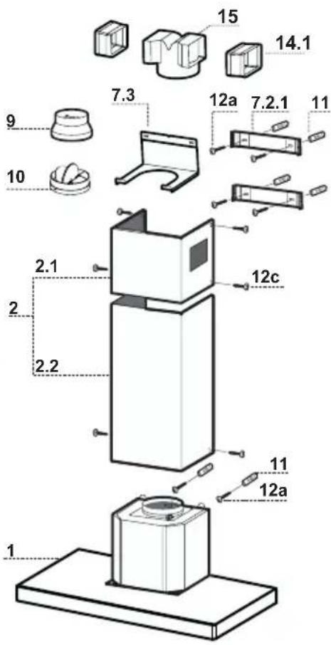
Components
| Ref. | Q.ty | Product | Components |
| 1 | 1 | Hood Body, complete with: Controls, Light, Blower, Filters | |
| 2 | 1 | Telescopic Chimney comprising: | |
| 2.1 | 1 | Upper | Section |
| 2.2 | 1 | Lower | Section |
| 9 | 1 | Reducer Flange ø 150-120 mm | |
| 10 | 1 | Damper ø 150 | |
| 14.1 | 2 | Air Outlet Connection Extension | |
| 15 | 1 | Air Outlet Connection | |
| Ref. | Q.ty | Installation Components |
| 7.2.1 | 2 | Upper Chimney Section Fixing Brackets |
| 7.3 | 1 | Air Outlet Connection Support |
| 11 | 6 Wall Plugs | |
| 12a | 6 Screws 4,2 x 44,4 | |
| 12c | 6 Screws 2,9 x 9,5 | |
| Q.ty | Documentation | |
| 1 | Instruction Manual | |
Wall drilling and bracket fixing
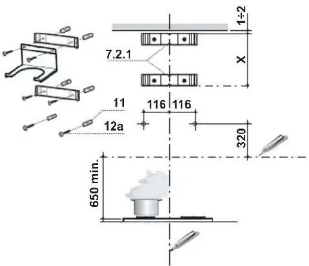
Wall marking:
- Draw a vertical line on the supporting wall up to the ceiling, or as high as practical, at the centre of the area in which the hood will be installed.
- Draw a horizontal line at 650 mm above the hob.
- Place bracket 7.2.1 on the wall as shown about 1-2 mm from the ceiling or upper limit aligning the centre (notch) with the vertical reference line.
- Mark the wall at the centres of the holes in the bracket.
- Place bracket 7.2.1 on the wall as shown at X mm below the first bracket (X = height of the upper chimney section supplied), aligning the centre (notch) with the vertical line.
- Mark the wall at the centres of the holes in the bracket.
- Mark a reference point as indicated at 116 mm from the vertical reference line and 320 mm above the horizontal reference line.
- Repeat this operation on the other side.
- Drill φ 8 mm holes at all the centre points marked.
- Insert the wall plugs 11 in the holes.
• Fix the lower bracket 7.2.1 using the 12a screws (4,2 x 44,4) supplied. - Fix the upper bracket 7.2.1 and the air outlet connection support 7.3 together using the 2 screws 12a (4,2 x 44,4) supplied.
- Insert the two screws 12a (4,2 x 44,4) supplied in the hood body fixing holes, leaving a gap of 5-6 mm between the wall and the head of the screw.
Mounting the hood body
- Before attaching the hood body, tighten the two screws Vr located on the hood body mounting points.
- Hook the hood body onto the screws 12a.
• Fully tighten support screws 12a. - Adjust screws Vr to level the hood body.
Connections
DUCTED VERSION AIR EXHAUST SYSTEM
When installing the ducted version, connect the hood to the chimney using either a flexible or rigid pipe φ 150 or 120mm, the choice of which is left to the installer.
To install a ø 150
• To install the dumper 10
- Fix the pipe in position using sufficient pipe clamps (not supplied).
To install a ø 120
- To install a φ 120 mm air exhaust connection, insert the reducer flange 9 on the dumper 10.
- Fix the pipe in position using sufficient pipe clamps (not supplied).
- Remove any activated charcoal filters.


RECIRCULATION VERSION AIR OUTLET
- Put connection 15 into the connection support 7.3.
- Insert the connection extension pieces laterally 14.1 in connection 15.
- Make sure that the outlet of the extension pieces 14.1 is horizontally and vertically aligned with the chimney outlets.
- Connect the air outlet connection 15 to the hood body outlet using either a flexible or rigid pipe 150 mm, the choice of which is left to the installer.
- Ensure that the activated charcoal filters have been inserted.

ELECTRICAL CONNECTION
- Connect the hood to the mains through a two-pole switch having a contact gap of at least 3 mm.
- Remove the grease filters (see paragraph Maintenance) being sure that the connector of the feeding cable is correctly inserted in the socket placed on the side of the fan.

Flue assembly
Upper exhaust flue
- Slightly widen the two sides of the upper flue and hook them behind the brackets 7.2.1, making sure that they are well seated.
- Secure the sides to the brackets using the 4 screws 12c (2,9 x 9,5) supplied.
- Make sure that the outlet of the extensions pieces is aligned with the chimney outlets.
Lower exhaust flue
- Slightly widen the two sides of the flue and hook them between the upper flue and the wall, making sure that they are well seated.
- Fix the lower part laterally to the hood body using the 2 screws 12c (2,9 x 9,5) supplied.


L Light Switches the lighting system on and off.
S Led Motor running led.
| V1 | Motor | Switches the extractor motor on and off at low speed. Used to provide a contin-uos and silent air change in the presence of light cooking vapours. |
| V2 | Speed | Medium speed, suitable for most operating conditions given the optimum treated air flox/noise level ratio. |
| V3 | Intensive | Maximum speed, used for eliminating the highest cooking vapour emission, including long periods. |
Grease filters
CLEANING METAL SELF- SUPPORTING GREASE FILTERS
- The filters must be cleaned every 2 months of operation, or more frequently for particularly heavy usage, and can be washed in a dishwasher.
- Remove the filters one at a time by pushing them towards the back of the group and pulling down at the same time.
- Wash the filters, taking care not to bend them. Allow them to dry before refitting.
- When refitting the filters, make sure that the handle is visible on the outside.

Activated charcoal filter (Recirculation version)
REPLACING THE ACTIVATED CHARCOAL FILTER
- The filter is not washable and cannot be regenerated, and must be replaced approximately every 4 months of operation, or more frequently for particularly heavy usage.
- Remove the metal grease filters
- Remove the saturated activated carbon filter by releasing the fixing hooks
• Fit the new filter by hooking it into its seating - Replace the metal grease filters.

Lighting
LIGHT REPLACEMENT
40 W incandescent light.
- Remove the screw fixing the Lighting support.
- Pull the Lighting support down.
- Extract the lamp and replace with another of the same type.
- Replace the lighting support in reverse order.

Removing the Grease Filters
Before carrying out Maintenance on the E-ASY CLEANING Suction Unit:
- Disconnect the hood by switching off the twopole switch on the mains power supply line, or by switching off the main power switch.
- Remove the grease filters from the hood.
- If the hood is of the recirculation type, remove the odour filters:
- For hoods with a flat cartridge (A): turn the fastening elements provided;
- For hoods with a bayonet cartridge (B): turn as indicated and extract.
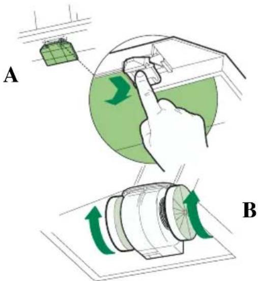
Disconnecting the EASY CLEANING Suction Unit
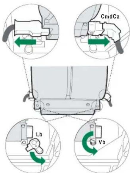
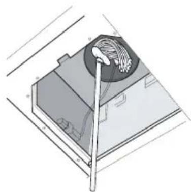
- Disconnect the power connector Ca and the control and lighting connector Cmd on the sides of the unit.
- For wall-mounted hoods and free-standing hoods with square chimney, turn the levers Lb locking the suction unit, so that they disconnect from the pins.
- For free-standing hoods with round chimney, unscrew the plugs Vb locking the suction unit.
- Pull the suction unit forwards so that it unhooks from the support pins, and remove it downwards through the air outlet.

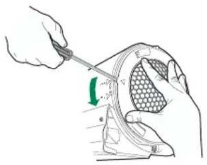
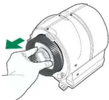
- To remove the side grilles protecting the fans, lift up the stop tooth using a knife or screwdriver and turn the grilles in the direction indicated by the arrow.
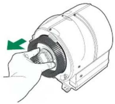
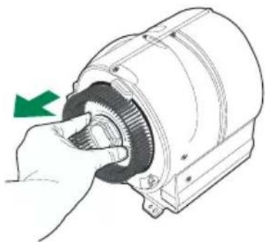
- Grasp the fans in the holes provided and pull to extract.
CLEANING
- Wash the fans and the protection grilles, using normal washing-up liquid. These elements can also be washed in the dish-washer.
- Using a damp cloth and a suitable detergent, clean the body of the suction device, taking great care not to allow any water to leak into the inside of the unit or into the connector housings.
- Leave until completely dry before reassembling.
- Using a brush, clean the air outlet pipe as far as you can reach.


N.B. To avoid reassembling the wrong way round, the two fans have different couplings.
- Reassemble the fans on the corresponding pins, pressing them until they snap into place.

- Fit the protection grilles so that the teeth coincide in the "FREE" position and when turned to "LOCK".
- Replace the EASY CLEANING suction unit on the hood, inserting it in position and connecting it to the support pins.
- Turn the lock levers, or screw in the lock plugs.
- Connect the power connector and the command connector to the sockets on the sides of the suction device.
- Replace any activated charcoal odour filters.
- Replace the grease filters.
- Connect the hood to the power supply system, by turning the two-pole switch on the mains power line to on, or by turning the main switch on.
- Check that the hood is working properly, by turning the motor and lighting on.

INSTALLATION
Dimensioner

Komponenter
Ref. Stk. Installationsdele
Montering af aftræk
∅verste aftræk
Aktivt kulfilter (recirkulationsudgave)
UDSKIFTNING AF DET AKTIVE KULFILTER
Belysning
UDSKIFTNING AF PÆRER
40 W glødelamper

RENG∅RING
INSTALLATION
Mått

Komponenter
MONTERING AV SKORSTEN
Kolfilter
Belysning
BYTE AV LAMPA
Glödlampor, 40W


RENGÖRING

INSTALLASJON
Dimensjoner

Deler
Ref. Antall Produktets deler
1 1 Kjøkkenviftens hoveddel komplett med: Kontroller, lys, vifteenhet, filtre.
Belysning
BYTTE AV LYSPÆRENE

- For å fjerne beskyttelseristene på siden av viftebladene må du løfte sperreanordningen med spissen til et skrujern eller en kniv og dreie dem i pilens retning.

- Ta tak i viftebladene i de bestemte hullene og trekk dem ut.
RENGJ∅RING


ASENNUS
Mitat

Hormin asennus
Ylähormi
Valaistus
LAMPUN VAIHTO
40 W:n hehkulamppu


PUHDISTUS

The symbol 📋 on the product or on its packaging indicates that this product may not be treated as household waste. Instead it shall be handed over to the applicable collection point for the recycling of electrical and electronic equipment. By ensuring this product is disposed of correctly, you will help prevent potential negative consequences for the environment and human health, which could otherwise be caused by inappropriate waste handling of this product. For more detailed information about recycling of this product, please contact your local city office, your household waste disposal service or the shop where you purchased the product.


- INSTRUCTIONS MANUAL INDEX
- RECOMMENDATIONS AND SUGGESTIONS
- INSTALLATION
- USE
- MAINTENANCE
- WALL DRILLING AND BRACKET FIXING
- WALL MARKING
- MOUNTING THE HOOD BODY
- CONNECTIONS
- DUCTED VERSION AIR EXHAUST SYSTEM
- TO INSTALL A Ø 150
- TO INSTALL A Ø 120
- RECIRCULATION VERSION AIR OUTLET
- ELECTRICAL CONNECTION
- FLUE ASSEMBLY
- UPPER EXHAUST FLUE
- LOWER EXHAUST FLUE
- GREASE FILTERS
- CLEANING METAL SELF- SUPPORTING GREASE FILTERS
- ACTIVATED CHARCOAL FILTER (RECIRCULATION VERSION)
- REPLACING THE ACTIVATED CHARCOAL FILTER
- LIGHTING
- LIGHT REPLACEMENT
- 40 W INCANDESCENT LIGHT
- REMOVING THE GREASE FILTERS
- DISCONNECTING THE EASY CLEANING SUCTION UNIT
- CLEANING
- MONTERING AF AFTRÆK
- ∅VERSTE AFTRÆK
- AKTIVT KULFILTER (RECIRKULATIONSUDGAVE)
- UDSKIFTNING AF DET AKTIVE KULFILTER
- BELYSNING
- UDSKIFTNING AF PÆRER
- 40 W GLØDELAMPER
- RENG∅RING
- MONTERING AV SKORSTEN
- KOLFILTER
- BYTE AV LAMPA
- GLÖDLAMPOR, 40W
- RENGÖRING
- INSTALLASJON
- DIMENSJONER
- DELER
- REF. ANTALL PRODUKTETS DELER
- BYTTE AV LYSPÆRENE
- RENGJ∅RING
- ASENNUS
- HORMIN ASENNUS
- YLÄHORMI
- VALAISTUS
- LAMPUN VAIHTO
- 40 W:N HEHKULAMPPU
- PUHDISTUS
Brand : FRANKE
Model : FDF 6146 XS ECS
Category : Range hood