
392-14 - Range hood FRANKE - Free user manual and instructions
Find the device manual for free 392-14 FRANKE in PDF.


| Product Type | Range hood |
| Brand | Franke |
| Model | 392-14 |
| Installation Type | Under cabinet / Wall-mounted |
| Width | 90 cm (approx.) |
| Depth | 50 cm (approx.) |
| Height | 60 cm (approx.) |
| Weight | 15 kg (approx.) |
| Power Supply | 220-240 V / 50 Hz |
| Max Power Consumption | 250 W (approx.) |
| Motor Type | Single motor |
| Number of Speeds | 3 speeds |
| Extraction Capacity | 600 m³/h (approx.) |
| Noise Level | 55 dB (max speed, approx.) |
| Lighting | 2 x 20 W halogen |
| Filter Type | Aluminum grease filter |
| Filter Cleaning | Dishwasher safe or hand wash |
| Venting Type | Ducted / Recirculation (with charcoal filter, optional) |
| Control Type | Push buttons |
| Safety Features | Thermal fuse, motor overload protection |
| Maintenance | Clean filters monthly; charcoal filter replace every 3-6 months |
| Spare Parts | Grease filters, charcoal filters, light bulbs, motor |
| Repairability Index | 7/10 (approx.) |
| Certification | CE, RoHS |
Frequently Asked Questions - 392-14 FRANKE
User questions about 392-14 FRANKE
0 question about this device. Answer the ones you know or ask your own.
Ask a new question about this device
Download the instructions for your Range hood in PDF format for free! Find your manual 392-14 - FRANKE and take your electronic device back in hand. On this page are published all the documents necessary for the use of your device. 392-14 by FRANKE.
USER MANUAL 392-14 FRANKE
natural_image
Illustration of a family celebrating with food and drinks, featuring cartoon characters, kitchen utensils, and snacks (no text or symbols)SV Bruksanvisning
Säkerhetsföreskrifter . . . . . . . . . . . . . . . . . . . . . . . . . . . . . . . . . .
Installation 4
Injustering av luftflöden . . . . . . . . . . . . . . . . . . . . . . . . . . . . . . . . . . . . . .
Användning 8
GB User instructions
Safety Instructions . . . . . . . . . . . . . . . . . . . . . . . . . . . . . . . . . . . . . .
Installation 11
Adjusting the air flow . . . . . . . . . . . . . . . . . . . . . . . . . . . . . . . . . . . . . . . . .
Instructions for use 16
Servicing and warranty . . . . . . . . . . . . . . . . . . . . . . . . . . . . . . . . . . . . . . . .
natural_image
Technical line drawing of a mechanical housing or bracket component (no text or symbols)TEKNISKA UPPGIFTER

Fig.1
Fig.7
Obs!
natural_image
Simple 3D diagram of a tray with an arrow and a small box, no text or symbols presentFig. 11
Please read this installation and user guide carefully before installing and using the product, paying special attention to the safety instructions.
Keep the instructions for reference or for the next owner.
Disconnect the product from the power supply prior to cleaning or maintenance.
§ Diversion of exhaust air shall be carried out in accordance with instructions issued by the appropriate authority.
§ Exhaust air may not be directed into flues that are used for fumes from items such as gas, wood or oil-burning stoves or fireplaces.
§ The distance between the stove and the product must be at least 45 cm. For gas hob, the distance should be increased to 65 cm. Adjust accordingly if the stove manufacturer recommends a higher mounting height.
§ For safety reasons, installation and replacement of cables or other types of connectors should only be carried out by a qualified professional.
§ You must not flambé food underneath the product.
§ If the hood is to be used at the same time as products that use energy sources other than electricity, i.e., gas hobs, gas, wood or oil-burning stoves or fireplaces, etc, the room must have an adequate supply of air.
§ The product may be used by children from 8 years of age and persons with mental, sensory or physical impairment, or a lack of experience and knowledge, provided they are given information about how the product is to be used.
§ Children should not be allowed to play with the product. Children must not undertake cleaning or maintenance of the product unsupervised.
§ Accessible parts of the product may become hot when food is being prepared.
§ A fire is more likely to spread if the product is not cleaned as frequently as indicated.
The cooker hood is intended for installation built into cupboards. The cooker hood is equipped with electronic control for EC motors, a motorised damper, LED lighting and a metal mesh filter. Installation, use, care, maintenance, etc., are described in these instructions.

natural_image
Technical line drawing of a mechanical housing or enclosure component (no text or symbols)TECHNICAL INFORMATION
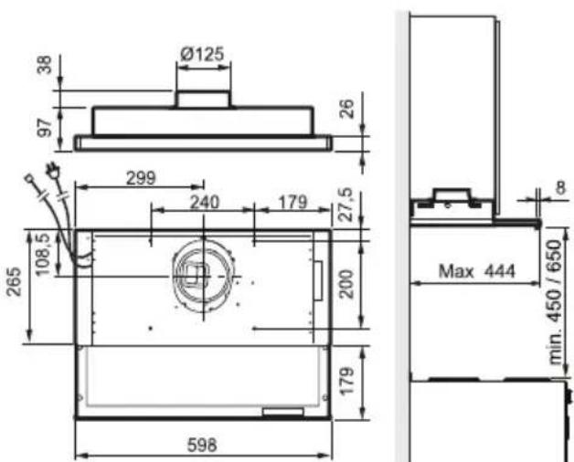
Fig. 1
| Measure-ments | see Fig. 1 |
| Electrical connection | 230 V ~ earthed. |
| Lighting LED | 2 x 2 W |
| Control cable | 1-10 VUpon delivery, the set-tings are 3, 5 and 10 V. |
INSTALLATION
Fixing parts, screws for mounting, etc. are supplied with the cooker hood.
Electrical installation
The cooker hood is supplied with an electrical cable and earthed plug for connection to an earthed wall socket as well as a low voltage cable for connection to an EC motor. The wall socket must be accessible after installation is complete.
Assembly of connecting sleeve coupling with damper

Fig. 2
The outlet air terminal device is supplied, fitted inside the cooker hood.
The damper shaft A should be positioned in the eye under the damper cover; see Fig. 2. Make sure that the tabs B end up under the edge of the plate and that the device snaps into place.
Assembly
Installation between or in cupboards without bases.

Fig. 3
The cooker hood is installed using brackets.
Mark out and fasten screws (3,5 x 13) so that they protrude a few millimetres from both cupboard sides as illustrated, Fig. 3A. If it is intended to align the underside of the cooker hood with the underside of the row of cupboards, use the upper measurement, 102, see Fig. 3A. The cooker hood brackets are adjustable to fit various cupboard depths, Fig. 3B.

Fig. 4
Move the cooker hood brackets without fully tightening the screws (3,5 x 6,5) helt och justera konsolerna så att de passar mot skåpsidorna, Fig. 4A. Hang the cooker hood in the pre-installed screws in the side of the cupboard. Tighten the screws in the bracket and on the wall, Fig. 4B. Lock the brackets into position using the locking screws, Fig. 4C (3,5 x 13).
Installation in cupboards with bases.
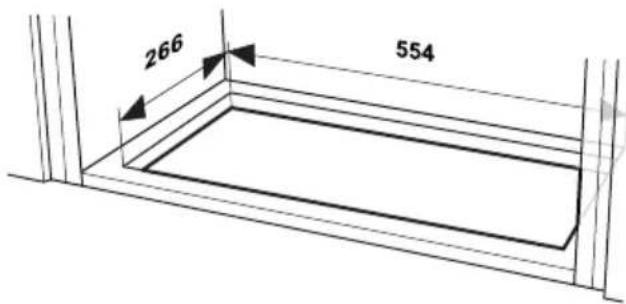
Fig. 5

Fig. 6
The cooker hood is installed using brackets.
Using a saw, cut out a hole in the base of the cupboard, Fig. 5. Attach the brackets as far into the cooker hood as possible. Insert the cooker hood up into the hole in the base of the cupboard. Pull out, Fig. 6A, oand use screws to fasten the brackets to the sides of the cupboard, Fig. 6B, with screws 3,5 x 13. Tighten the brackets in the cooker hood.
Connection to exhaust flue
Connect the cooker hood with a pipe or tubing ∅ 125 mm.

Fig. 7
Attention!
When using connecting tubing, the tubing must be stretched and assembled to fit directly next to the connection, Fig. 7.
Removal of protective plastic
Remove all protective plastic from the filter and any other parts of the product.
CHANGING THE AIR VOLUME VIA REPROGRAMMING CONTROL
The speeds are reprogrammable from 1 to 10 V.
Upon delivery, the settings are 3 V for speed 1, 5 V for speed 2 and 10 V for speed 3.

Always start by adjusting the lowest speed setting and then go on to the higher speeds. There must be a lower voltage at speed 1 than at speed 2 and a lower voltage at speed 2 than at speed 3. Start with whole volts and make fine adjustments to tenths of a volt.
Activate programming mode
All settings must be made in programming mode.

Press and hold buttons A and B for approx. 5 seconds. The indicator lights are illuminated during this period. When they start flashing the control is in programming mode.
Attention!
If no button is pressed for 30 seconds, programming mode is exited and the previously set voltages remain.
Save settings
Once programming is complete, save the settings by holding in buttons A and B for approx. 5 seconds. During this period the indicator lights are illuminated. When they go out, the settings have been saved.
Reprogramming speeds
Activate programming mode

Select the speed you want to change by pressing button C, D or E.
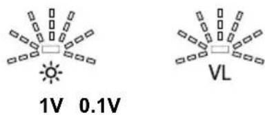
The selected button is illuminated and the voltage is indicated via flashes. First button A which indicates whole volts, then button B which indicates tenths of a volt.
Raise the voltage by pressing button A. Each press of the button gives 1 volt more and is indicated by an extra flash.
The same procedure applies to button B (tenths of a volt).

Lower the voltage by holding a speed button in for 5 seconds. The voltage then falls and is adjusted to the lowest possible setting. From there you can step up to the desired voltage. Save the settings.
Factory reset
Activate programming mode

To revert to the factory settings, hold in buttons A and E for 5 seconds. During this period the indicator lights flash. When they go out, the reset has been completed.
SETTING THE DAMPER
Basic flow

Fig. 8
Basic ventilation is set by moving the sliding damper A to the desired position according to marking B, Fig. 8. (See diagram, page 39.)
Measuring pressure drop
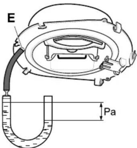
Fig. 9
The pressure drop is measured by fitting the hose on the measuring port E at the front edge of the coupling, Fig. 9.
FUNCTION SWITCH
Central fan is always running in standard mode for general and sanitary ventilation.

Fig. 10
A. Lighting.
B. Increased general and sanitary ventilation. The central fan runs at top speed. Returns to basic ventilation after 60 minutes.
C. Open damper. Speed 1 on fan motor.
D. Open damper. Speed 2 on fan motor.
E. Open damper. Speed 3 on fan motor.
The damper closes automatically after 60 minutes and the central fan returns to standard mode. It can also be returned to standard mode by pressing in the activating button one more time.
Ideally, keep the damper open a short while before and after cooking, in order to avoid the spread of odours in the room.
CHANGING SWITCH FUNCTIONS
Switch functions can be changed by reprogramming the button panel. (Contact Customer Services.)
CARE AND MAINTENANCE
Cleaning
The cooker hood should be cleaned with a damp cloth and washing-up liquid. With normal usage, the filters must be cleaned at least every other month. Clean more often after intensive use.
natural_image
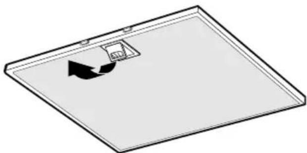
Simple 3D diagram of a tray with an arrow pointing to a small box, no text or symbols presentFig. 11
Remove the grease filters by opening the snap retainer, Fig. 11 Handle the filters carefully, taking care not to bend them.
Soak the filter in a solution of warm water and washing-up liquid. The filter can also be washed in a dishwasher.
Refit the grease filters after cleaning, making sure they snap firmly into place.
The inside of the cooker hood and the damper must be cleaned at least twice a year. Wipe with a damp cloth and washing-up liquid. The damper is easiest to clean when it is open.
REPLACEMENT OF LED LIGHTING AND LED DRIVER

flowchart
graph LR
    A["Light Source"] --> B["LED"]
    B <--> C["LED"]
    C --> D["Output 230V"]
Fig. 12
Attention!
The replacement of the LED lighting and LED driver must be carried out by an authorised professional. Contact the service organisation.
If the lighting and driver are damaged, they must be replaced with an equivalent special light fixture and driver from the manufacturer or its service agent.
Check that the fuse is intact. Go through all the functions to check what is not working.
Contact Franke Service
Tel. +46 (0)912-40 500
www.franke.se/service
They can help you fix the problem or refer you to the nearest service agent for fast and effective service.
The product is covered by the relevant EHL provisions.
PACKAGING AND PRODUCT RECYCLING
The packaging should be deposited at your nearest
recycling point.
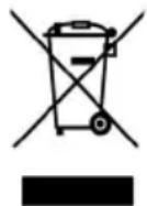
The symbol means that the product must not be treated as household waste. It should instead be taken to a collection point for the recycling of electrical and electronic components. By ensuring that the product is dealt with in the correct manner, you are helping to prevent the adverse environmental and health effects that could arise if the product was disposed of as regular waste. For further information on recycling, contact your local authority or waste disposal service, or the store where you purchased your product.
natural_image
Technical line drawing of a mechanical housing or bracket component (no text or symbols)TEKNISKE DATA
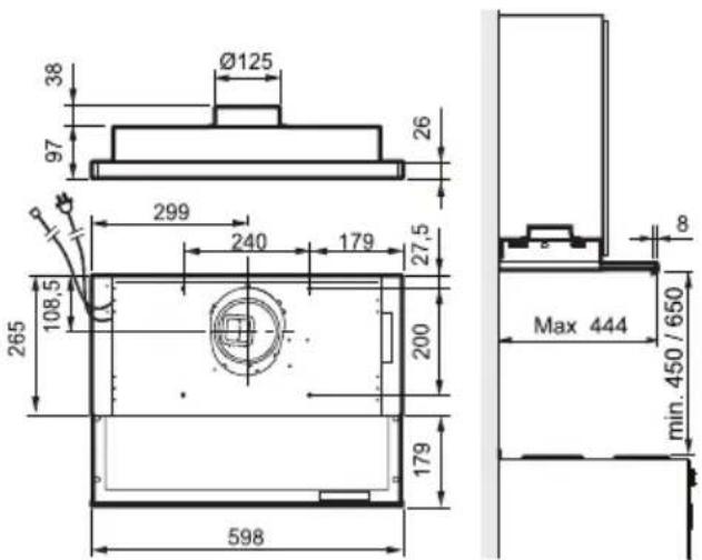
Fig. 1
| Mål | se Fig. 1 |
| Elektrisk tilslutning | 230 V ~ med jordforbindelse. |
| Belysning LED | 2 x 2 W |
| Styrekabel | 1 - 10 VVed levering er indstillingerne 3, 5 og 10 V. |
INSTALLATION
Fig. 7
Obs!
natural_image
Two abstract geometric symbols: a sun with radiating lines and a square with a central dot, labeled 'VL' (no text or numbers present)1V 0.1V
natural_image
Simple 3D diagram of a tray with an arrow indicating direction and a small box on top (no text or symbols)Fig. 11
natural_image
Technical line drawing of a mechanical housing component (no text or symbols)TEKNISET TIEDOT

Kuva 1
Kuva 7
Huom!
natural_image
Simple 3D diagram of a rectangular plate with an arrow pointing to a small square containing a grid, no text or symbols present.Kuva 11
natural_image
Technical line drawing of a mechanical housing or bracket component (no text or symbols)TEKNISKE DATA

Fig. 1
| Mål | se Fig. 1 |
| Elektrisk tilkobling | 230 V – med vernejording |
| Belysning LED | 2 x 2 W |
| Hovedled-ning | 1 - 10 VVed levering er innstillingene 3, 5 og 10 V. |
INSTALLASJON
Fig. 7
Merk:
PLEIE OG VEDLIKEHOLD
Rengjøring
natural_image
Simple 3D diagram of a tray with an arrow indicating direction and a small box on top (no text or symbols)Fig. 11



- SV Bruksanvisning
- GB User instructions
- Obs!
- INSTALLATION
- Electrical installation
- Assembly of connecting sleeve coupling with damper
- Assembly
- Connection to exhaust flue
- Attention!
- Removal of protective plastic
- CHANGING THE AIR VOLUME VIA REPROGRAMMING CONTROL
- Activate programming mode
- Save settings
- Reprogramming speeds
- Factory reset
- SETTING THE DAMPER
- FUNCTION SWITCH
- CHANGING SWITCH FUNCTIONS
- CARE AND MAINTENANCE
- Cleaning
- REPLACEMENT OF LED LIGHTING AND LED DRIVER
- PACKAGING AND PRODUCT RECYCLING
- Huom!
- Kuva 11
- INSTALLASJON
- Merk:
- PLEIE OG VEDLIKEHOLD
- Rengjøring
Brand : FRANKE
Model : 392-14
Category : Range hood