
ALLIANCE 604-10 - Range hood FRANKE - Free user manual and instructions
Find the device manual for free ALLIANCE 604-10 FRANKE in PDF.


| Product Type | Range Hood |
| Brand | Franke |
| Model | ALLIANCE 604-10 |
| Installation Type | Under-cabinet or Wall-mounted |
| Width | 60 cm |
| Depth | 50 cm |
| Height (Minimum) | 70 cm |
| Height (Maximum) | 100 cm |
| Weight | 15 kg |
| Power Supply | 220-240 V ~ 50/60 Hz |
| Motor Power | 200 W |
| Extraction Rate (Max) | 600 m³/h |
| Noise Level (Max) | 65 dB(A) |
| Number of Speeds | 3 |
| Control Type | Push buttons |
| Lighting | LED |
| Filter Type | Aluminum grease filter |
| Ducted/Recirculation | Both possible (charcoal filter optional) |
| Annual Energy Consumption | 50 kWh |
| Maintenance | Clean grease filter monthly |
| Safety Features | Automatic shut-off timer, motor thermal protection |
Frequently Asked Questions - ALLIANCE 604-10 FRANKE
User questions about ALLIANCE 604-10 FRANKE
0 question about this device. Answer the ones you know or ask your own.
Ask a new question about this device
Download the instructions for your Range hood in PDF format for free! Find your manual ALLIANCE 604-10 - FRANKE and take your electronic device back in hand. On this page are published all the documents necessary for the use of your device. ALLIANCE 604-10 by FRANKE.
USER MANUAL ALLIANCE 604-10 FRANKE
natural_image
Illustration of a family's dining scene with kitchen, drinks, and food items (no text or symbols)SV Bruksanvisning
Säkerhetsföreskrifter . . . . . . . . . . . . . . . . . . . . . . . . . . . . . . . . . .
Installation 4
Injustering av luftflöden . . . . . . . . . . . . . . . . . . . . . . . . . . . . . . . . . . . . . .
Användning 7
GB User instructions
Safety Instructions . . . . . . . . . . . . . . . . . . . . . . . . . . . . . . . . . . . . .
Installation 11
Adjusting air flow 13
Instructions for use 14
Service and warranty ....
natural_image
Technical line drawing of a mechanical assembly with a base plate and cylindrical component (no text or symbols)TEKNISKA UPPGIFTER

Fig.1
Fig.5
Obs!
natural_image
Simple 3D diagram of a rectangular plate with an arrow pointing to a small square containing a checkmark (no text or symbols)Fig.9
natural_image
Illustration of hands using a tool to adjust a mesh component (no text or symbols present)Fig.11
natural_image
Technical line drawing of a mechanical component with arrows indicating assembly or adjustment (no text or symbols present)Fig.12
Please read this installation and user guide carefully before installing and using the product, paying special attention to the safety instructions.
Keep the instructions for reference or for the next owner.
Disconnect the product from the power supply prior to cleaning or maintenance.
§ Diversion of exhaust air shall be carried out in accordance with instructions issued by the appropriate authority.
§ Exhaust air may not be directed into flues that are used for fumes from items such as gas, wood or oil-burning stoves or fireplaces.
§ The distance between the stove and the product must be at least 45 cm. For gas hob, the distance should be increased to 65 cm. Adjust accordingly if the stove manufacturer recommends a higher mounting height.
§ For safety reasons, installation and replacement of cables or other types of connectors should only be carried out by a qualified professional.
§ You must not flambé food underneath the product.
§ If the hood is to be used at the same time as products that use energy sources other than electricity, i.e., gas hobs, gas, wood or oil-burning stoves or fireplaces, etc, the room must have an adequate supply of air.
§ The product may be used by children from 8 years of age and persons with mental, sensory or physical impairment, or a lack of experience and knowledge, provided they are given information about how the product is to be used.
§ Children should not be allowed to play with the product. Children must not undertake cleaning or maintenance of the product unsupervised.
§ Accessible parts of the product may become hot when food is being prepared.
§ A fire is more likely to spread if the product is not cleaned as frequently as indicated.
The cooker hood is intended for installation under, built into or between cupboards. The cooker hood is equipped with Easy Clean™ motor package, LED lighting and a metal mesh filter. Installation, use, care, maintenance etc., are described in these instructions.

natural_image
Technical line drawing of a mechanical assembly with a base plate and cylindrical component (no text or symbols)TECHNICAL INFORMATION
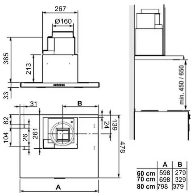
Fig. 1
Measurements see Fig. 1
Electrical 230 V \~ earthed installation
Lighting LED 2 x 2 W
INSTALLATION
Fixing parts, screws for mounting, etc. are supplied with the cooker hood.
Electrical installation
The cooker hood is supplied with a cable and earthed plug for connection to an earthed socket. The socket should be accessible after installation is complete.
Assembly
Remove grease filter and motor unit, see Fig. 9 and Fig. 10.
Installing damper unit
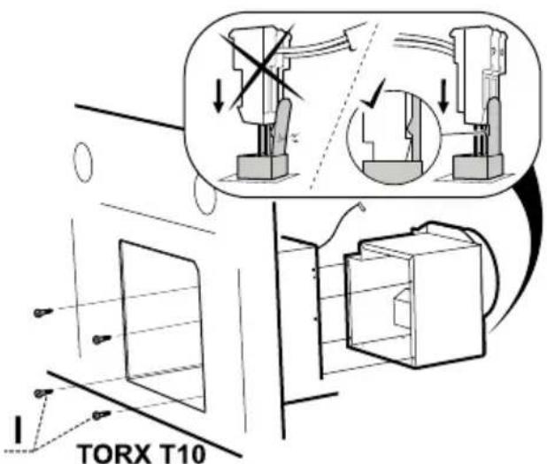
Fig.2
Lay hood and damper unit on a flat surface. Screw the damper unit into the cooker hood with screws I.

Fig. 3

Fig. 4
The cooker hood can be placed under, between or built into cupboards. When installed under cupboards, the cooker hood is screwed into place with four 3.8 x 30 screws, Fig. 3. When placed between or built into cupboards, the cooker hood is installed with the aid of brackets. Brackets and cooker hood must be screwed into place with eight 3.5 x 13 screws, Fig. 4. The brackets are screwed into place with the bevelled corners facing out and level with the front edge of the cupboard, Fig. 4A, or with the bracket facing the front section of the hood upper cupboard, Fig. 4B. The cooker hood is then screwed into the brackets. Reinstall motor unit and filter.
Connection to exhaust flue
Connect the cooker hood with a pipe or tubing ∅160 mm. If the connection is ∅125 mm a reducing coupling sleeve must be used.

natural_image
Technical diagram showing two mechanical assembly states with cross symbols indicating failure or failure (no text or labels present)Fig. 5
Attention!
When using connecting tubing, the tubing must be stretched and installed directly adjacent to the connection, Fig. 5.
Removal of protective plastic
Remove all protective plastic from the filter and any other parts of the product.
CHANGE OF AIR VOLUME VIA REPROGRAMMING
The air volume at the highest speed can be reduced by reprogramming via the power switch. (contact Customer service.)
SETTING THE DAMPER
The air flow is adjusted with the aid of the damper. The damper can be accessed for adjustment by removing the filter and the motor unit.
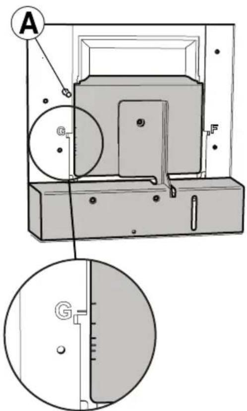
Fig. 6
Measurement outlet
The measurement pressure Pm is measured in the measurement outlet, Fig. 6A. With the aid of the measurement pressure Pm and the position of the damper, the volume of air can be read off in the adjustment diagram, where G1-G6 are basic ventilation. If the volume of air has to be altered, read off a new damper setting from the diagram and then adjust the position of the damper according to the following description.
Adjusting basic ventilation

Fig. 7
Adjust the basic ventilation with the damper hatch closed. Undo the screws, Fig. 7E. Move the damper hatch, Fig. 7F, to the desired position.
Attention!
Handle the damper with care.
The markings for the position of the damper hatch, G1-G6, correspond with the values in the diagram Basic ventilation, see Fig.14, page 38.
Lock the damper hatch in place with the screws, Fig. 7E.
Measure the pressure Pm and check that the desired basic flow is achieved.
FUNCTION SWITCH

Fig. 8
A. Lighting
B. Ventilation mode. Open damper. Returns to basic ventilation after 60 minutes.
C. Speed 1 on fan motor.
D. Speed 2 on fan motor.
E. Speed 3 on fan motor.
The damper and the alliance fan motor closes automatically after 60 minutes. You can also return to basic mode by pressing the active button once more.
It is a good idea to open the damper a short while before and after cooking, in order to avoid the spread of odours in the room. Adjust the speed of the fan depending on the type of food you are preparing. Preferably allow the fan to run on low speed for a while after cooking. If needed, also use the fan's low speed when the oven is in use, or after using the dishwasher.
CARE AND MAINTENANCE
Cleaning
The cooker hood should be cleaned with a damp cloth and washing-up liquid. With normal usage, the filters must be cleaned at least every other month. Clean more often after intensive use.

natural_image
Simple 3D diagram of a rectangular plate with an arrow pointing to a small square containing a grid, no text or symbols present.Fig. 9
Remove the grease filters by opening the snap retainer, Fig. 9 Handle the filters carefully, taking care not to bend them.
Soak the filter in a solution of warm water and washing-up liquid. The filter can also be washed in a dishwasher.
Refit the grease filters after cleaning, making sure they snap firmly into place.

Fig. 10
The inside of the fan and the damper must be cleaned at least twice a year. Wipe with a damp cloth and washing-up liquid. The damper is easiest to clean when it is open. The impellers and the side grilles must be cleaned at least twice a year.
The motor core is removed by first disconnecting the contact on the side of the motor unit, Fig. 10A. Rotate the latches, Fig. 10B, that lock the motor core in place. Pull the unit outwards so that it is freed from the pins, and then downwards.
Attention!
The motor core should not be washed or exposed to moisture!
natural_image
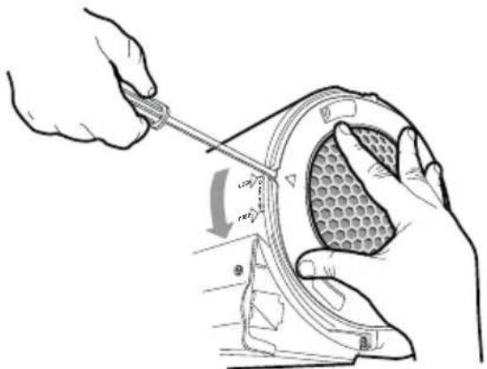
Illustration of a hand using a tool to adjust a mesh component, showing angle and direction (no text or symbols)Fig. 11
The side grilles are detached by lifting up the stop lug with a screwdriver and rotating the grille in the direction of the arrow, Fig. 11.

natural_image
Technical line drawing of an electric motor with a hand operating it, showing internal components and mounting holes (no text or symbols)Fig. 12
The impellers are removed by pressing together the plastic tabs in the centre of the wheels while simultaneously pulling the wheels outwards, Fig. 12.
The impeller and side grilles should be cleaned in warm water with washing-up liquid. The parts can also be washed in a dishwasher.
After washing and drying, assemble the parts in reverse order. Check that the parts snap into place and that the motor assembly and electrical connector are properly seated.
REPLACEMENT OF LED LIGHTING AND LED DRIVER

flowchart
graph LR
    A["LED"] <--> B["LED"]
    C["230V"] --> D["LED"]
Fig. 13
Attention!
The replacement of the LED lighting and LED driver must be carried out by an authorised professional. Contact the service organisation.
If the lighting and driver are damaged, they must be replaced with an equivalent special light fixture and driver from the manufacturer or its service agent.
Check that the fuse is intact. Go through all the functions to check what is not working.
Contact Franke Service
Tel. +46 (0)912-40 500
www.franke.se/service
They can help you fix the problem or refer you to the nearest service agent for fast and effective service.
The product is covered by the relevant EHL provisions.
PACKAGING AND PRODUCT RECYCLING
The packaging should be deposited at your nearest
recycling point.
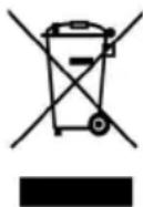
The symbol means that the product must not be treated as household waste. It should instead be taken to a collection point for the recycling of electrical and electronic components. By ensuring that the product is dealt with in the correct manner, you are helping to prevent the adverse environmental and health effects that could arise if the product was disposed of as regular waste. For further information on recycling, contact your local authority or waste disposal service, or the store where you purchased your product.
ECO-DESIGN DIRECTIVE
The product meets and is tested in accordance with the eco-design requirements of European Regulation 66/2014.
natural_image
Technical line drawing of a mechanical assembly with a base plate and cylindrical component (no text or symbols)TEKNISKE DATA
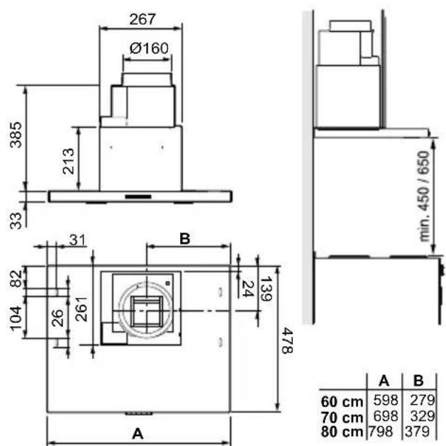
Fig. 1
| Mål | se Fig. 1 |
| Elektrisk tilslutning | 230 V ~ med jordforbindelse |
| Belysning LED | 2 x 2 W |
INSTALLATION
Fig. 5
Obs!
natural_image
Simple 3D diagram of a flatboard with a small box and arrow, no text or symbols presentFig. 9
natural_image
Illustration of hands using a tool to adjust a mesh component (no text or symbols present)Fig. 11
natural_image
Technical illustration of a mechanical component with arrows indicating assembly or adjustment (no text or symbols present)Fig. 12
natural_image
Technical line drawing of a mechanical assembly with a base plate and cylindrical component (no text or symbols)TEKNISET TIEDOT

Kuva 1
Mitat ks. Kuva 1
Kuva 5
Huom!
natural_image
Simple 3D diagram of a rectangular plate with a small square and arrow indicating rotation or movement (no text or symbols)Kuva 9
natural_image
Illustration of a hand using a tool to adjust a mesh component, showing angle measurement (no text or symbols)Kuva 11
natural_image
Technical line drawing of an electric motor with a hand operating it, showing internal components and a gray arrow indicating direction (no text or symbols present)Kuva 12
natural_image
Technical line drawing of a mechanical assembly with a base plate and cylindrical component (no text or symbols)TEKNISKE DATA
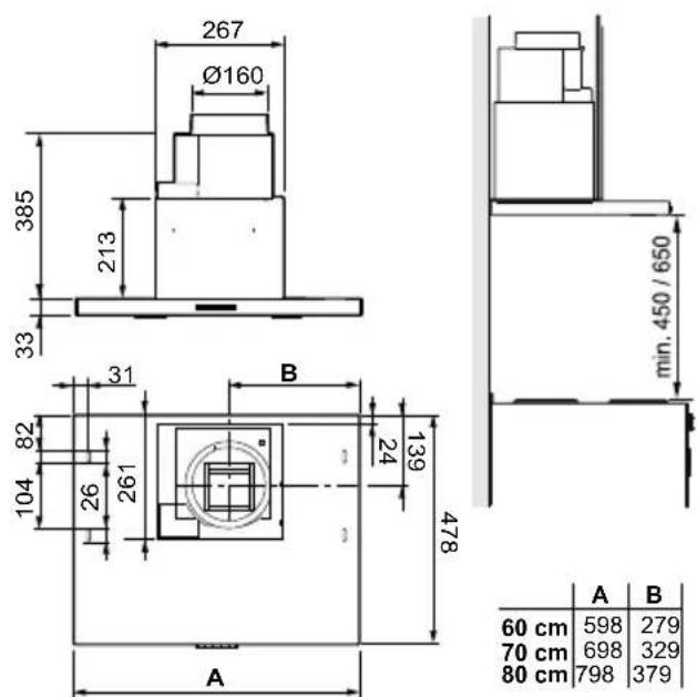
Fig. 1
| Mål | se Fig. 1 |
| Elektrisk tilkobling | 230 V ~ med vernejording |
| Belysning LED | 2 x 2 W |
INSTALLASJON
Monteringsdetaljer, festeskruer m.m. leveres sammen med kjøkkenventilatoren.
Fig. 5
Merk:
Plasser spjeldluken, Fig. 7F, i ønsket stilling.
Merk:
PLEIE OG VEDLIKEHOLD
Rengjøring
natural_image
Simple 3D diagram of a rectangular plate with an arrow pointing to a small square containing a box, no text or symbols present.Fig. 9
Legg filteret i varmt vann blandet med oppvaskmiddel. Filteret kan også vaskes i oppvaskmaskin.
natural_image
Illustration of hands using a tool to adjust a mesh component (no text or symbols present)Fig. 11
natural_image
Technical illustration of a mechanical component with arrows indicating assembly or adjustment (no text or symbols present)Fig. 12



- SV Bruksanvisning
- GB User instructions
- Obs!
- INSTALLATION
- Electrical installation
- Assembly
- Connection to exhaust flue
- Attention!
- Removal of protective plastic
- CHANGE OF AIR VOLUME VIA REPROGRAMMING
- SETTING THE DAMPER
- Measurement outlet
- FUNCTION SWITCH
- CARE AND MAINTENANCE
- Cleaning
- REPLACEMENT OF LED LIGHTING AND LED DRIVER
- PACKAGING AND PRODUCT RECYCLING
- ECO-DESIGN DIRECTIVE
- Kuva 5
- Huom!
- INSTALLASJON
- Merk:
- PLEIE OG VEDLIKEHOLD
- Rengjøring
Brand : FRANKE
Model : ALLIANCE 604-10
Category : Range hood