
M6995 - Home trainer HMS Premium - Free user manual and instructions
Find the device manual for free M6995 HMS Premium in PDF.


| Product Type | Magnetic home trainer / exercise bike |
| Model | M6995 |
| Brand | HMS Premium |
| Dimensions (L x W x H) | 92 x 55 x 142.5 cm |
| Net Weight | 28 kg |
| Flywheel Weight | 7 kg |
| Maximum User Weight | 120 kg |
| Resistance System | Magnetic (manual 1–16 levels) |
| Display Type | LCD dot matrix |
| Displayed Metrics | RPM, speed, time, distance, calories, pulse, watts, recovery heart rate |
| Training Programs | 12 preset programs (P1–P12), 4 user programs (U1–U4), random, HRC (55%, 75%, 90%, target), watts constant |
| Heart Rate Monitoring | Hand pulse sensors (L/R) |
| Power Supply | AC adapter (included) |
| Frame Material | Steel |
| Pedals | Adjustable with toe cages (9/16" thread) |
| Seat Adjustment | Vertical (seat post) and horizontal (sliding) |
| Handlebar Adjustment | Vertical (handle post) |
| Transport Wheels | Yes, on front stabilizer |
| Safety Class | HC (home use) per EN ISO 20957-1 |
| Warranty | 24 months (parts and labor) |
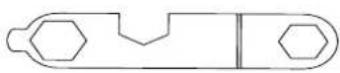
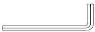
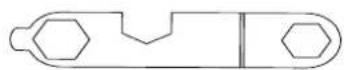
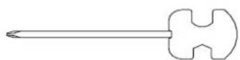
| Included Tools | Allen wrenches (6 mm), N-type tool, harpoon wrench 13/15 |
Frequently Asked Questions - M6995 HMS Premium
User questions about M6995 HMS Premium
0 question about this device. Answer the ones you know or ask your own.
Ask a new question about this device
Download the instructions for your Home trainer in PDF format for free! Find your manual M6995 - HMS Premium and take your electronic device back in hand. On this page are published all the documents necessary for the use of your device. M6995 by HMS Premium.
USER MANUAL M6995 HMS Premium
natural_image
Line drawing of a stationary exercise bike with adjustable arms and legs (no text or symbols)INSTRUKCJA UŻYTKOWANIA – MANUAL INSTRUCTION NÁVOD K OBSLUZE – BEDIENUNGSANLEITUNG
LISTA KONTROLNA PRZED MONTAZEM
| NR CZEŚCI | OPIS | ILOŚĆ |
| 1 | KOMPUTER | 1 |
| 3 | OSŁONA PRZEDNIA | 1 |
| 8 | SŁUPEK KOMPUTERA | 1 |
| 9 | OSŁONA SŁUPKA KOMPUTERA | 1 |
| 13 | SIODEŁKO | 1 |
| 16 | WSPORNIK SIODEŁKA | 1 |
| 21 | SZTYCA | 1 |
| 28 | PEDAL (P) 9/16 " | 1 |
| 43 | STABILIZATOR TYLNY | 1 |
| 44 | RAMA GŁÓWNA | 1 |
| 58 | PEDAL (L) 9/16 " | 1 |
| 62 | STABILIZATOR PRZEDNI | 1 |
| 67 | OSŁONA TYLNA | 1 |
| 79 | KIEROWNICA | 1 |
| 90 | ADAPTER | 1 |
| LISTA CZĘŚCI I NARZĘDZI | 1 |
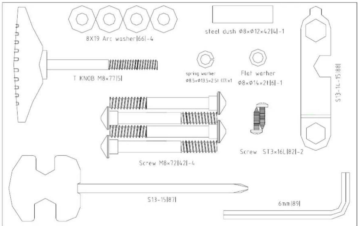
LISTA NARZĘDZI
natural_image
Line drawing of a mechanical tool with a handle and spiral grip (no text or symbols)5
82
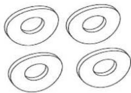
natural_image
Four identical hand-drawn oval shapes with internal concentric circles, no text or symbols present.66
4
88
42
6

7
89
87
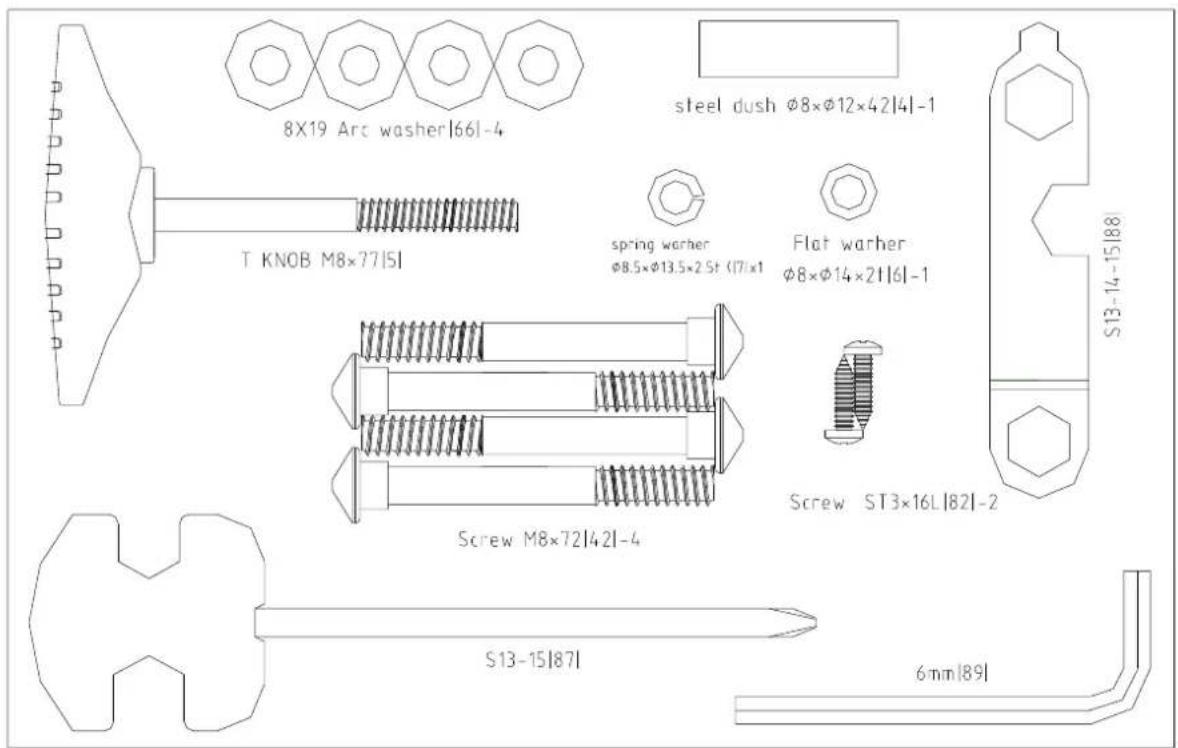
| NR CZĘŚCI | OPIS | ILOŚĆ |
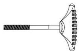
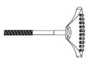
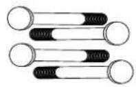
| 5 | POKRETŁO TYPU T (M8*77mmL) | 1 |
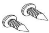
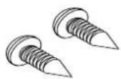
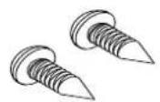
| 82 | ŚRUBA(ST3*16) | 2 |
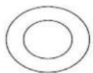
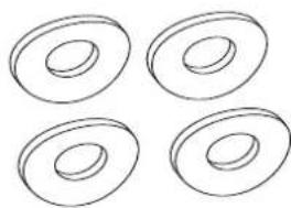
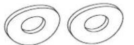
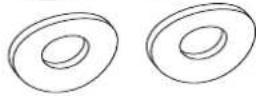
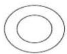
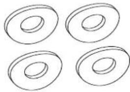
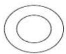
| 66 | PODKŁADKA(∅8*∅19*2T) | 4 |
| 4 | TULEJA(φ8*φ12*42mmL) | 1 |
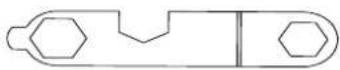
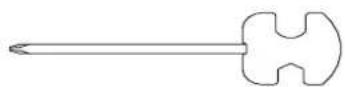
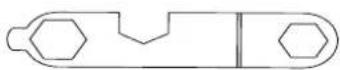
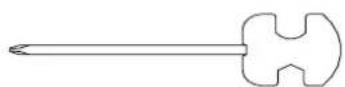
| 88 | NARZĘDZIE TYPU N | 1 |
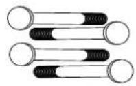
| 42 | ŚRUBA(M8X72L) | 4 |
| 6 | PŁASKA PODKŁADKA (φ8*φ14*2t) | 1 |
| 7 | PODKŁADKA SPREŻYNUJĄCA (φ8.5*φ13.5*2.5t) | 1 |
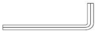
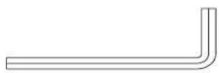
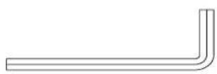
| 89 | KLUCZ SZEŚCIOKĄTNY 6MM*30MML*84MML | 1 |
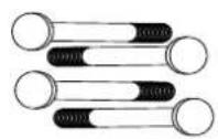
| 87 | KLUCZ HARPUNOWY 13.15 | 1 |
LISTA CZEŚCI I NARZĘDZI
| Nr | OPIS | Ilość | Nr | OPIS | Ilość | |
| 1 | KOMPUTER | 1 | 46 | ŚRUBA(M8*20) | 1 | |
| 2 | PRZEWÓD GÓRNY | 1 | 47 | WSPORNIK | 1 | |
| 3 | POKRYWA PRZEDNIA | 1 | 48 | TULEJA( 10* 14*3mm ) | 1 | |
| 4 | TULEJA( 8* 12*42mmL ) | 1 | 49 | KOŁO | 1 | |
| 5 | POKRĘTŁO TYPU T (M8*77mmL) | 1 | 50 | PŁASKA PODKŁADKA( 8* 22*1T ) | 1 | |
| 6 | PŁASKA PODKŁADKA( 8* 14*2t ) | 1 | 51 | ŁOŻYSKO(6000) | 2 | |
| 7 | PODKŁADKA SPREŻYNUJĄCA( 8.5* 13.5*2.5t ) | 1 | 52 | PŁASKA PODKŁADKA( 8* 14*2T ) | 1 | |
| 8 | SŁUPEK KOMPUTERA | 1 | 53 | ŚRUBA (M6*12) | 2 | |
| 9 | OSŁONA SŁUPKA KOMPUTERA | 1 | 54 | DŹWIGNIA | 1 | |
| 10 | POKRĘTŁO SIODEŁKA | 1 | 55 | ŚRUBA (M8*55L) | 1 | |
| 11 | OSŁONA SZTYCY | 1 | 56 | MAGNES | 1 | |
| 12 | ŚRUBA (M4*8L) | 1 | 57 | OSŁONA ŁAŃ CUCHA (L) | 1 | |
| 13 | SIODEŁKO | 1 | 58 | PEDAL(L)9/16" | 1 | |
| 14 | PŁASKA PODKŁADKA( 8* 16*2T ) | 3 | 59 | ŚRUBA(ST4*50L) | 7 | |
| 15 | NAKRĘTKA NYLONOWA(M8) | 6 | 60 | OSŁONA PRZEDNICH KÓŁEK | 2 | |
| 16 | WSPORNIK SIODEŁKA | 1 | 61 | ŚRUBA(ST3*8L) | 2 | |
| 17 | TULEJA | 1 | 62 | STABILIZATOR PRZEDNI | 1 | |
| 18 | OSŁONA SZTYCY | 1 | 63 | CZUJNIK | 1 | |
| 19 | PŁASKA PODKŁADKA( 10* 25*2T ) | 1 | 64 | ŚRUBA(M3*8L) | 2 | |
| 20 | POKRĘTŁO | 1 | 65 | ŚRUBA(M8*16) | 4 | |
| 21 | SZTYCA | 1 | 66 | PODKŁADKA( 8* 19*2T ) | 8 | |
| 22 | PLASTIKOWA TULEJA | 1 | 67 | OSŁONA TYLNA | 1 | |
| 23 | OŚ | 1 | 68 | ŚRUBA(M5*16) | 2 | |
| 24 | KOŁO PASOWE( 232 ) | 1 | 69 | SPREŻYNA | 1 | |
| 25 | KORBA L/P | 1 | 70 | SILNIK | 1 | |
| 26 | PAS | 1 | 71 | ŁOŻYSKO 6203 | 1 | |
| 27 | OSŁONA ŁAŃ CUCHA (R) | 1 | 72 | PRZEWÓD CZUJNIKA POMIARU PULSU | 1 | |
| 28 | PEDAL(P) 9/16" | 1 | 73 | PŁASKA PODKŁADKA( 8* 14*2t ) | 1 | |
| 29 | OSŁONA KORBY L/P | 2 | 74 | ŚRUBA | 1 | |
| 30 | ŚRUBA (3/16" *3/4") | 6 | 75 | PRZEWÓD DC | 1 | |
| 31 | NAKRĘTKA 3/8"-26*7T | 2 | 76 | UCHWYT PIANKOW L/P | 2 | |
| 32 | NAKRĘTKA3/8"-26*3.8T | 3 | 77 | UCHWYT PIANKOWY L/P | 2 | |
| 33 | OŚ KOŁA ZAMACHOWEGO 3/8-26"*140L | 1 | 78 | CZUJNIK POMIARU PULSU L/P | 2 | |
| 34 | ŁOŻYSKO 6900 | 2 | 79 | KIEROWNICA | 1 | |
| 35 | KOŁO PASOWE MAŁE 30 | 1 | 80 | OSŁONA | 2 | |
| 36 | ŁOŻYSKO 6003 | 2 | 81 | ŚRUBA(ST3*10) | 6 | |
| 37 | ŁOŻYSKO 35*17 | 1 | 82 | ŚRUBA(ST3*16) | 2 | |
| 38 | KOŁO ZAMACHOWE( 240 ) | 1 | 83 | ŚRUBA (M5*12) | 4 | |
| 39 | ŁOŻYSKO 6300 | 1 | 84 | ŚRUBA (M8*P1.25*55L*S28L) | 1 | |
| 40 | TULEJA( 10* 15.8*9mm ) | 1 | 85 | PŁASKA PODKŁADKA( 6* 13*1T ) | 2 | |
| 41 | ZAŚLEPKA TYLNA | 2 | 86 | ŚRUBA (M6*20) | 2 | |
| 42 | ŚRUBA ( M8*72L) | 4 | 87 | KLUCZ HARPUNOWY13.15 | 1 | |
| 43 | STABILIZATOR TYLNY | 1 | 88 | NARZĘDZIE TYPU N | 1 | |
| 44 | RAMA GŁÓ WNA | 1 | 89 | KLUCZ SZEŚCIOKĄTNY6mmX30mmlX84mml | 1 | |
| 45 | SPREŻYNA | 1 | 90 | ADAPTER | 1 | |
| 91 | PRZEWÓD DOLNY | 1 |
Instrukcja montażu
KROK 1
natural_image
Line drawing of a stationary exercise bike with adjustable arms and control panel (no text or symbols)KROK 8: Przymocuj adapter.
KOMPUTER
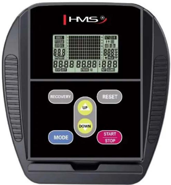
FUNKCJE
IMPORTANT SAFETY INFORMATION
This product has been designed for home use only and built for optimum safety. Please note the following safety precautions:
- Before starting any exercise program you should consult your doctor to determine if you have any physical or health conditions that could create a risk to your health and safety, or prevent you from using the equipment properly. Your doctor's advice is essential if you are taking medication that affects your heart rate, blood pressure or cholesterol level. This is especially important for persons over the age of 35, pregnant women, or those with pre-existing health problems or balance impairments.
- Before using this equipment to exercise, always do stretching exercises to properly warm up.
- Be aware of your body's signals. Incorrect or excessive exercise can damage your health. Stop exercising if you experience any of the following symptoms: pain, tightness in your chest, irregular heartbeat, extreme shortness of breath, feeling light headed, dizzy or nauseous. If you do experience any of these conditions you should consult your doctor before continuing with exercise program. Injuries to health may result from incorrect or excessive training.
- During exercises and after keep children and pets away from the equipment.
- Use the equipment on a solid, flat level surface with a protective cover for your floor or carpet. Move all sharp objects.
- Free area shall be not less than 0,6 m greater than the training area in the directions from which the equipment is accessed. Free area must also include the area for emergency dismount. Where equipment is positioned adjacent to each other the value of the free area may be shared.
- Before each use, visually inspect the unit including hardware and resistance bends.
- Before using the equipment, check if the nuts, bolts and other bends are securely tightened.
- Always use the equipment as indicated. If you find any defective components whilst assembling or checking the equipment, or if you hear any unusual noise coming from the equipment while using, stop. Do not use the equipment until the problem has been rectified.
- Do not insert any object into any openings.
- Be aware of all regulation and constructions parts which may disturb during exercises.
- The safety level of the equipment can only be maintained if it is regularly examined for damage and/or wear and tear.
- Wear suitable clothing whilst using the equipment. Avoid wearing loose clothing which may get caught in the equipment or that may restrict or prevent movement.
- The equipment has been tested and certified according to EN ISO 20957-1 under class HC. It is not suitable for therapeutic use.
- Care must be taken when lifting or moving the equipment so as not to injure your back. Always use proper lifting techniques and/or use assistance.
- The equipment is designed for adult use only. Keep unsupervised children away from the equipment.
- Assemble this unit as described in this manual. Use only parts from the set. Check all parts with the part list.
WARNING: READ ALL INSTRUCTIONS BEFORE USING ANY FITNESS EQUIPMENT. WE ASSUME NO RESPONSIBILITY FOR PERSONAL INJURY OR PROPERTY DAMAGE CAUSED BY OR THROUGH THE USE OF THIS PRODUCT
SPECIFICATIONS
Weight - 28 kg
Flywheel - 7 kg
Dimensions - 92 x 55 x 142,5 cm
Maximum weight of user - 120 kg
MAINTENANCE
Your unit has been carefully designed to require minimum maintenance. To ensure this, we recommend that you do the following: keep your unit clean by wiping sweat, dust or other residue off with a soft, clean cloth after each use. Always make sure that the bands are secure and show no signs of wear. Regularly check the tightness of nuts and bolts.
BREAKING
Stop to pedal when you want stop the item. Magnetic bike M6995 does not acquire breaking system or emergency break.
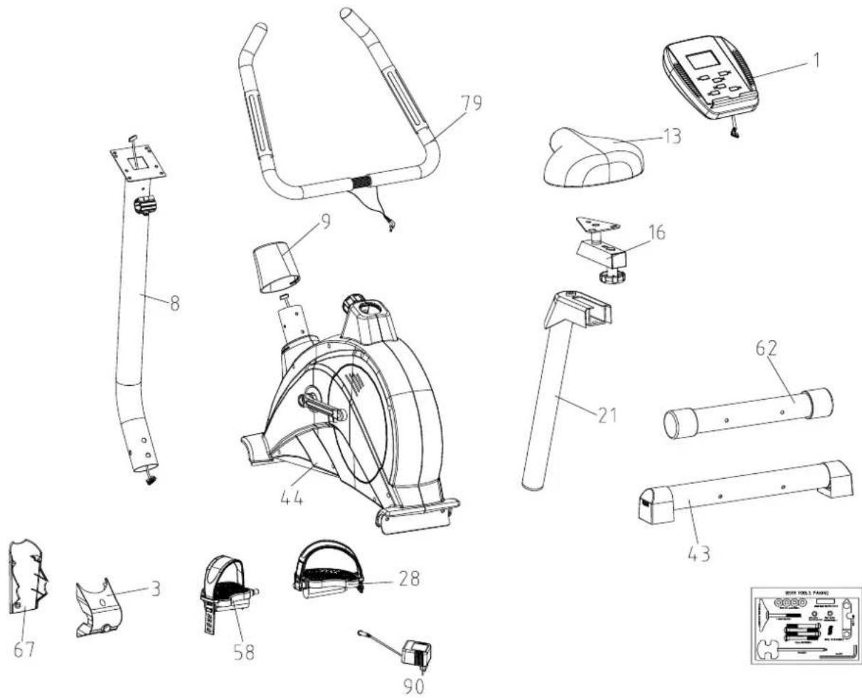
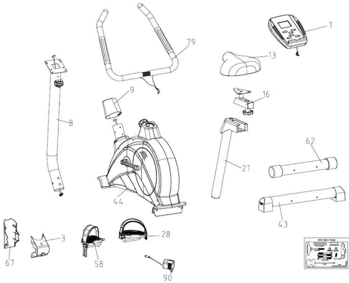
Exploded drawing:
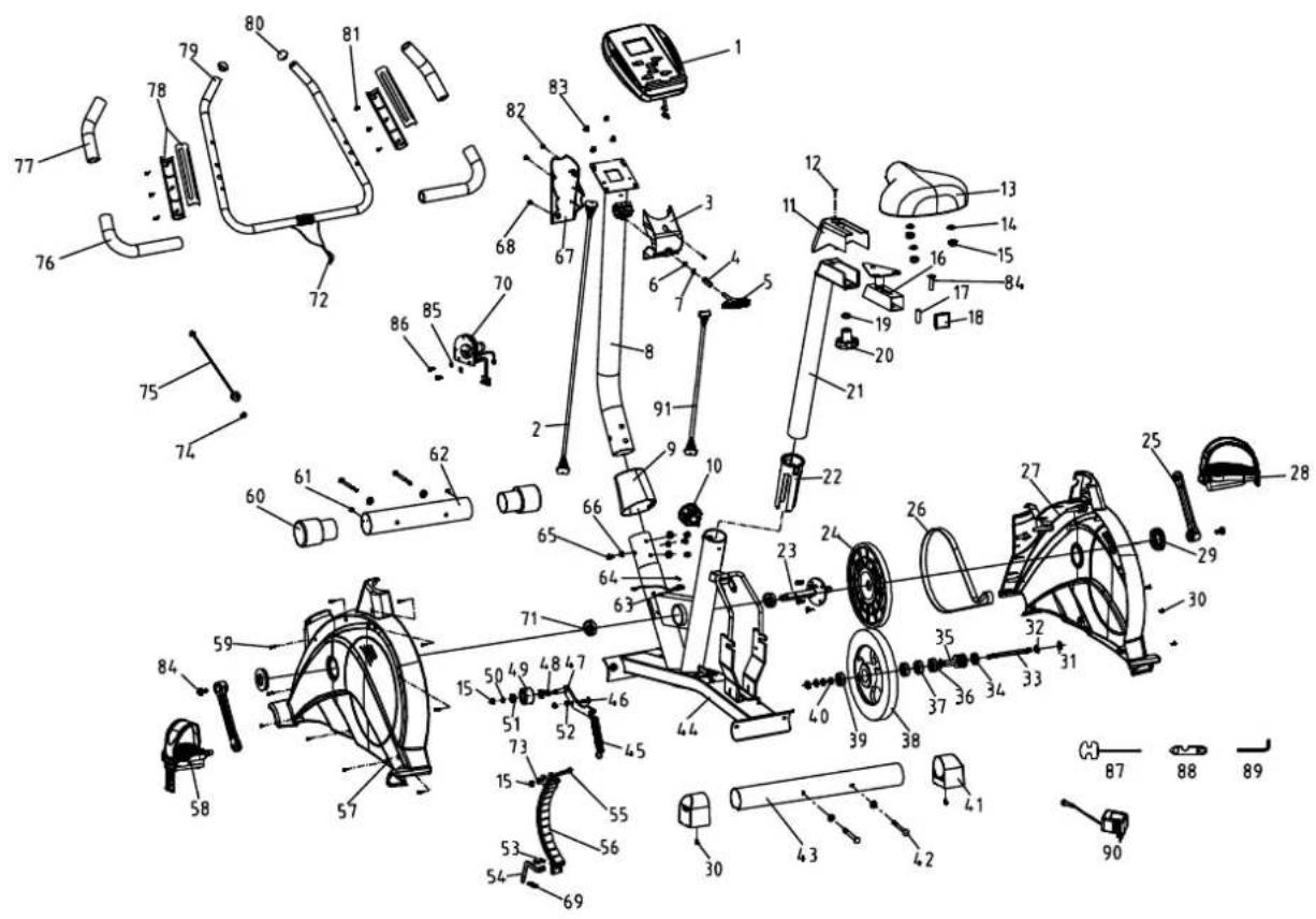
PARTS LIST AND TOOLS
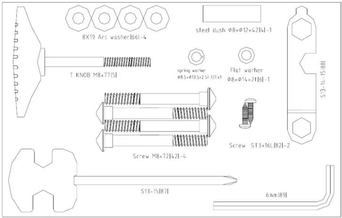
PRE-ASSEMBLY CHECK LIST
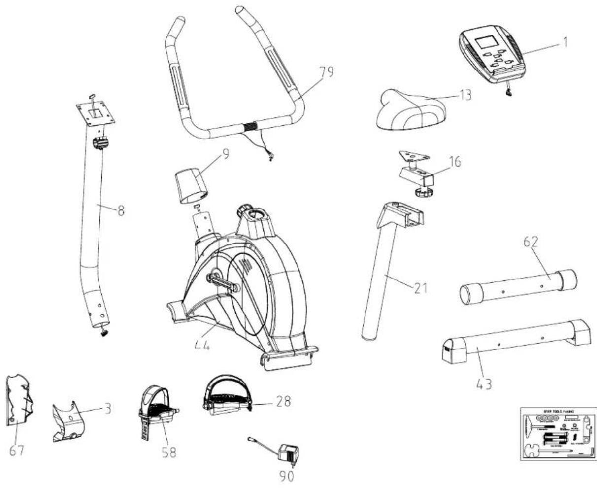
| PART NO | DESCRIPTION | QTY |
| 1 | COMPUTER | 1 |
| 3 | FRONT COVER | 1 |
| 8 | HANDLE POST | 1 |
| 9 | HANDLE POST COVER | 1 |
| 13 | SEAT | 1 |
| 16 | SLIDING PIECE | 1 |
| 21 | SEAT POST | 1 |
| 28 | PEDAL (R) 9/16 " | 1 |
| 43 | REAR STABILIZER | 1 |
| 44 | MAIN FRAME | 1 |
| 58 | PEDAL (L) 9/16 " | 1 |
| 62 | FRONT STABILIZER | 1 |
| 67 | REAR COVER | 1 |
| 79 | HANDLE BAR | 1 |
| 90 | ADAPTOR | 1 |
| PARTS LIST AND TOOLS | 1 |
HARDWARE PARTS LIST
natural_image
Illustration of a mechanical tool with a handle and spring-like end (no text or symbols)5
82
natural_image
Four hand-drawn oval shapes with internal concentric circles, no text or symbols present66
4
88
42
6

7
89
87
| PART NO | DESCRIPTION | QTY |
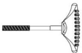
| 5 | T KNOB(M8*77mmL) | 1 |
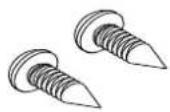
| 82 | SCREW(ST3*16) | 2 |
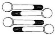
| 66 | WASHER(∅8*∅19*2T) | 4 |
| 4 | BUSHING(φ8*φ12*42mmL) | 1 |
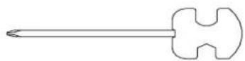
| 88 | N TYPE TOOL | 1 |
| 42 | SCREW(M8X72L) | 4 |
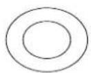
| 6 | FLAT WASHER(φ8*φ14*2t) | 1 |
| 7 | SPRING WASHER(φ8.5*φ13.5*2.5t) | 1 |
| 89 | HEX WRENCH 6MM*30MML*84MML | 1 |
| 87 | HARPOON WRENCH 13.15 | 1 |
PARTS LIST AND TOOLS
| NO | Description | Q'ty | NO | Description | Q'ty | |
| 1 | COMPUTER | 1 | 46 | SCREW(M8*20) | 1 | |
| 2 | UPPER CABLE | 1 | 47 | IDLER BAR | 1 | |
| 3 | FRONT COVER | 1 | 48 | BUSHING(Φ10*φ14*3mm) | 1 | |
| 4 | BUSHING(Φ8*φ12*42mmL) | 1 | 49 | WHEEL | 1 | |
| 5 | T KNOB(M8*77mmL) | 1 | 50 | FLAT WASHER(Φ8*φ22*1T) | 1 | |
| 6 | FLAT WASHER(Φ8*φ14*2t) | 1 | 51 | BEARING(6000) | 2 | |
| 7 | SPRING WASHER(Φ8.5*φ13.5*2.5t) | 1 | 52 | FLAT WASHER(Φ8*φ14*2T) | 1 | |
| 8 | HANDLE POST | 1 | 53 | SCREW (M6*12) | 2 | |
| 9 | HANDLE POST COVER | 1 | 54 | LEVER | 1 | |
| 10 | SEAT KNOB | 1 | 55 | SCREW (M8*55L) | 1 | |
| 11 | COVER FOR SEAT POST | 1 | 56 | MAGNET | 1 | |
| 12 | SCREW (M4*8L) | 1 | 57 | CHAIN COVER (L) | 1 | |
| 13 | SEAT | 1 | 58 | PEDAL(L)9/16" | 1 | |
| 14 | FLAT WASHER(Φ8*φ16*2T) | 3 | 59 | SCREW(ST4*50L) | 7 | |
| 15 | NYLON NUT(M8) | 6 | 60 | FRONT END CAP AND WHEEL | 2 | |
| 16 | SLIDING PIECE | 1 | 61 | SCREW(ST3*8L) | 2 | |
| 17 | BUSHING | 1 | 62 | FRONT STABILIZER | 1 | |
| 18 | SEAT POST PLASTIC COVER | 1 | 63 | SENSOR | 1 | |
| 19 | FLAT WASHER(φ10*φ25*2T) | 1 | 64 | SCREW(M3*8L) | 2 | |
| 20 | HORIZONTAL KNOB | 1 | 65 | SCREW (M8*16) | 4 | |
| 21 | SEAT POST | 1 | 66 | WASHER(φ8*φ19*2T) | 8 | |
| 22 | PLASTIC SLEEVE FOR SEAT POST | 1 | 67 | REAR COVER | 1 | |
| 23 | AXLE | 1 | 68 | SCREW(M5*16) | 2 | |
| 24 | PULLEY(φ232) | 1 | 69 | Spring | 1 | |
| 25 | CRANK L/R | 1 | 70 | MOTOR | 1 | |
| 26 | BELT | 1 | 71 | BEARING 6203 | 1 | |
| 27 | CHAIN COVER (R) | 1 | 72 | HAND PULSE WIRE | 1 | |
| 28 | PEDAL(R) 9/16" | 1 | 73 | FLAT WASHER (Φ8*φ14*2t) | 1 | |
| 29 | CRANK COVER L/R | 2 | 74 | SCREW | 1 | |
| 30 | SCREW(3/16" *3/4") | 6 | 75 | DC WIRE | 1 | |
| 31 | NUT 3/8"-26*7T | 2 | 76 | FOAM GRIP L/R | 2 | |
| 32 | NUT 3/8"-26*3.8T | 3 | 77 | FOAM GRIP L/R | 2 | |
| 33 | FLYWHEEL SHAFT 3/8-26"*140L | 1 | 78 | HAND PULSE L/R | 2 | |
| 34 | BEARING 6900 | 2 | 79 | HANDLE BAR | 1 | |
| 35 | SMALL PULLEY Φ30 | 1 | 80 | COVER | 2 | |
| 36 | BEARING 6003 | 2 | 81 | SCREW(ST3*10) | 6 | |
| 37 | ONE WAY BEARING Φ35*17 | 1 | 82 | SCREW(ST3*16) | 2 | |
| 38 | FLYWHEEL(φ240) | 1 | 83 | SCREW (M5*12) | 4 | |
| 39 | BEARING 6300 | 1 | 84 | BOLT (M8*P1.25*55L*S28L) | 1 | |
| 40 | BUSHING(Φ10*Φ15.8*9mm) | 1 | 85 | FLAT WASHER(Φ6*φ13*1T) | 2 | |
| 41 | REAR END CAP | 2 | 86 | SCREW(M6*20) | 2 | |
| 42 | SCREW ( M8*72L) | 4 | 87 | HARPOON WRENCH13.15 | 1 | |
| 43 | REAR STABILIZER | 1 | 88 | N TYPE TOOL | 1 | |
| 44 | MAIN FRAME | 1 | 89 | HEX WRENCH 6mmX30mmlX84mml | 1 | |
| 45 | SPRING | 1 | 90 | ADAPTOR | 1 | |
| 91 | LOWER CABLE | 1 |
Assembly instruction
STEP 1
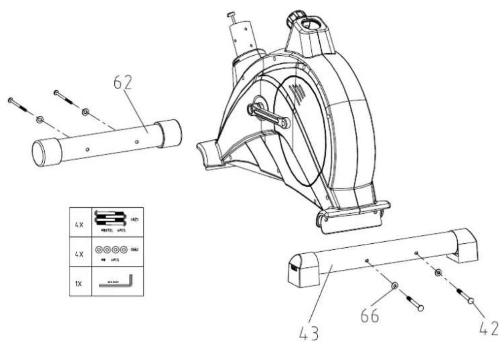
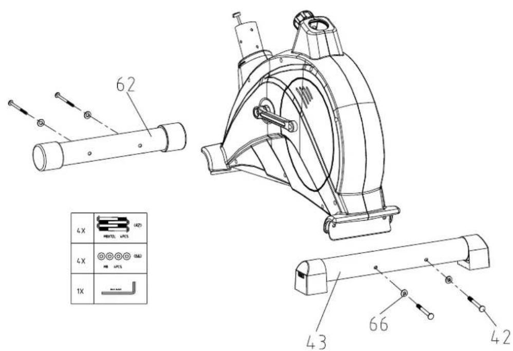
STEP 1: Assemble front and rear stabilizer
Fix front the stabilizer (62) and rear stabilizer (62) using screw (42) and washer (66), tighten using hex wrench.
STEP 2
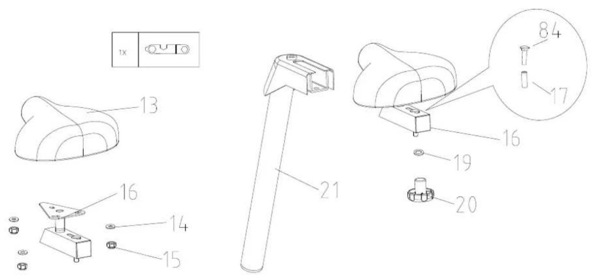
STEP 2: Assemble seat
- Loosen the nut and washer on the seat (13), use N tool and fix on the sliding (16).
- Loosen the knob (20), washer (19), bushing (17), screw (84) that on the sliding, then insert seat into the seat post (21).
6.Screw (84), bushing (17), washer (19) and knob (20) fix on the sliding(16).
STEP 3
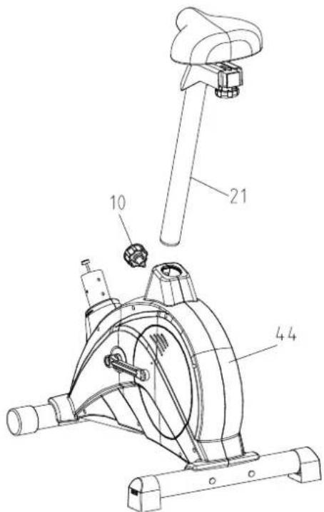
STEP 3: Assemble seat post
- Loosen knob (10) from main frame (44).
- Insert seat post (21) into the frame (44).
- Lock the knob (10).
STEP 4
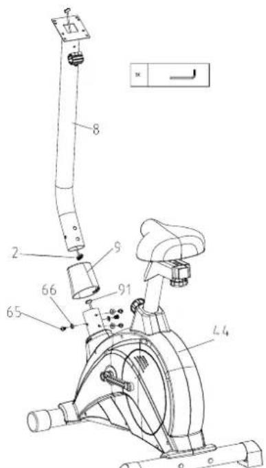
STEP 4: Assemble upright post
- Loosen screw (65) and washer (66) from the main frame (44).
- Connect upper cable (2) with lower cable (91).
- Insert upright post (8) into the frame (44).
- Use hex wrench to tighten screw (65) and washer (66)
- Insert handle post cover (9) into the frame.
STEP 5
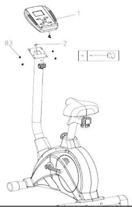
STEP 5: Assemble computer
- Use harpoon wrench to tighten the screws on the back of the computer.
- Connect upper cable (2) with the computer (1).
- Use harpoon to tighten screw (83).
STEP 6
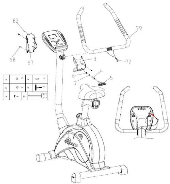
STEP 6: Assemble handlebar
- Insert the handlebar (79) into the dotted line position.
- Use harpoon wrench to tighten T knob (5) with bushing (4), washer (7), washer (6), fix front cover (3) using screw (82).
- Fix rear cover (67) using screw (68).
- Insert the line (72) into the computer (1).
STEP 7
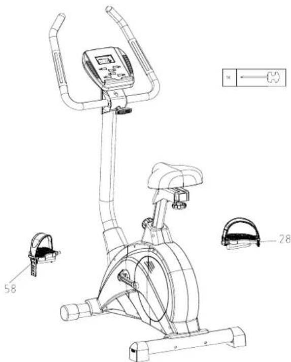
STEP 7: Assemble pedals
Use harpoon wrench to tighten left pedal (58) and right pedal (28).
STEP 8
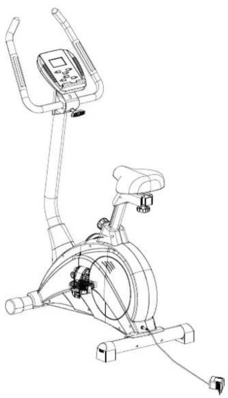
natural_image
Line drawing of a stationary exercise bike with mounted equipment (no text or symbols)STEP 8: Assemble adaptor.
COMPUTER
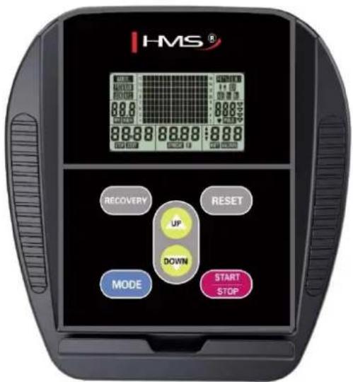
FUNCTION
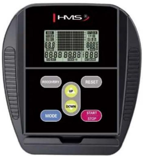
SCAN : Alternates between WATTS/CALORIES and RPM/SPEED. 6 seconds per display.
RPM:0\~15\~999
SPEED:0.0\~99.9 km/h
TIME:0:00\~99:59
DISTANCE : 0.00\~99.99 km
CALORIES : 0\~999
MANUAL : 1\~16 level
PROGRAM : P1\~P12
USER : U1\~U4
H.R.C : 55%、75%、90%、IND (TARGET)
PULSE : P\~30\~240, max value is available
USER DATA : U0 \~U4 (U1 \~ U4 programs set by the user)
WATTS : 0\~999 watts
WATTS CONSTANT :10\~350
FUNCTION DESCRIPTION
MANUAL Set the resistance level using the dot matrix display then (if required) set exercise parameters TIME/DISTANCE / CALORIES / PULSE then press START/STOP to start manual program.
- Set your exercising TIME by pressing UP ▲/DOWN ▼ from 0:00 to 99:00.
- Set your exercising DISTANCE by pressing UP ▲/DOWN ▼ from 0.00\~99.50 km
- Set your exercising CALORIES by pressing UP ▲/DOWN ▼ from 0\~990
- Set your target PULSE (HEART RATE) by pressing UP ▲/DOWN ▼ from P\~30\~240.
- Press MODE to confirm each value setting.
- If you don't need to set above value (TIME/DISTANCE / CALORIES / PULSE), press ST/STOP to quick start your exercising workout.
PROGRAM 12 automatic adjusting programs with control exercise (P1\~P12), Resistance level can be adjusted during PROGRAM DIAGRAM is flashing.
- Choose program profile P1 – P12 which workout program you want to challenge.
- In the program you can raise the load level by UP ▲/DOWN ▼.
- Set your program TIME by pressing UP ▲/DOWN ▼ from 0:00 to 99:00.
- Set your program DISTANCE by pressing UP ▲/DOWN ▼ from 0.00\~99.50 km.
- Set your program CALORIES by pressing UP ▲/DOWN ▼ from 0\~990.
- Set your target PULSE (HEART RATE) by pressing UP ▲/DOWN ▼ from P\~30\~240.
- Press MODE to confirm each value setting.
WATTS CONSTANT User can default WATTS value at his/her desire 10-350 watts between 10\~350 watts by using the UP/ DOWN knob. To fix WATTS constant value and then press ST/STOP key. Use WATTS control mode to train yourself in different WATTS's constant.
- Set up WATTS you want to constant by pressing UP ▲/DOWN ▼ from 10-350 while you are working out.
- Set your exercising TIME by pressing UP ▲/DOWN ▼ from 0:00 to 99:00.
- Set your exercising DISTANCE by pressing UP ▲/DOWN ▼ from 0.00\~99.50 km
- Set your exercising CALORIES by pressing UP ▲/DOWN ▼ from 0\~990
- Set your target PULSE (HEART RATE) by pressing UP ▲/DOWN ▼ from P\~30\~240.
- Press MODE to confirm each value setting.
USER Create your own Program profile through U1\~U4 by setting the resistance level for each individual segment. Then the Program will be automatically saved for future use. U0 ENTER can be set the same as U1\~U4 but this Program cannot be saved.
- User design your ideal program profile for each load in 16 levels.
- For example, user pressing UP ▲/DOWN ▼ to input his/her resistance load from 1-16 dot matrix.
- Press MODE to confirm each resistance load setting.
- Finish the resistance program chart.
-
Set your exercising TIME by pressing UP ▲/DOWN ▼ from 0:00 to 99:00.
-
Set your exercising DISTANCE by pressing UP ▲/DOWN ▼ from 0.00\~99.50 km
- Set your exercising CALORIES by pressing UP ▲/DOWN ▼ from 0\~990
- Set your target PULSE (HEART RATE) by pressing UP ▲/DOWN ▼ from P\~30\~240.
- Press MODE to confirm each value setting.
H.R.C HEART RATE CONTROL- Select your own target Heart Rate of choose one of the preset programs 55%, 75%, or 90%. Please enter your age into the User Data to ensure that your target heart rate is set correctly. The PULSE display will flash when you have reached your target heart rate according to the Program you have chosen.
i. 55% -- DIET PROGRAM
ii. 75% -- HEALTH PROGRAM
iii. 90% -- SPORTS PROGRAM
iv. TARGET—USER SET TARGET HEART RATE
- Set your own target HEART RATE of choose one of the preset programs 55%, 75%, 90% or Target.
- Set your target Heart Rate in the LCD window 30-240.
- Set your exercising TIME by pressing UP ▲/DOWN ▼ from 0:00 to 99:00.
- Set your exercising DISTANCE by pressing UP ▲/DOWN ▼ from 0.00\~99.50 km.
- Set your exercising CALORIES by pressing UP ▲/DOWN ▼ from 0\~990.
RANDOM PORGRAM A randomly selected program by the computer that will automatically generate its graph.
- There are total 16 bars: Every random will result load value of bar.
- After START, user can press UP ▲ / DOWN ▼ to adjust the load values of whole bar.
RECOVERY
When you have finished your workout, press RECOVERY. For RECOVERY to function correctly, it needs your Heart Rate input. TIME will count down from 1 minute and then your fitness level from F1 to F6 will be displayed.
NOTE: during RECOVERY, no other displays will operate.
F 1 \~ F6 = RECOVERY HEART RATE LEVEL
| Condition | Score | Heart Rate |
| Excellent | F1 | Above 50 |
| Good | F2 | 40 ~ 49 |
| Average | F3 | 30 ~ 39 |
| Fair | F4 | 20 ~ 29 |
| Poor | F5 | 10 ~ 19 |
| Very Poor | F6 | Under 10 |
USER DATA : U0\~U4 are user's Personal Programs (refer Personal). Users should enter their gender, age, height and weight. Only data for U1 to U4 will be saved.
- Press UP ▲/DOWN▼ to choose and identify you are user U0 / U1 / U2 /U3 / U4.
- Press UP ▲/DOWN ▼ to choose MALE / FEMALE.
- Input your AGE from 30 by pressing UP ▲/DOWN ▼. If you are 32 year-old, up to 32
- Input your Ht: HEIGHT by pressing UP ▲/DOWN ▼.
- Input your Wt:WEIGHT by UP ▲/DOWN ▼.
- Press MODE key to confirm your setting.
KEY FUNCTIONS
- MODE : Function select and confirmation key.
- UP ▲/DOWN ▼ : Increase and decrease or select option. 3. START/STOP KEY : START / STOP key.
- RECOVERY : Fitness test by measuring your recovery rate.
- RESET : Clean the pre-set value to 0.
TIPS
- Option: Plug in AC Adaptor
- Keep moisture away from computer.
Cardio – Training:
Before programming your training, it is essential to take account of your age, particularly for people of more than 35 years of age, as well as your physical condition. If you have a sedentary lifestyle without regular physical activity, it is vital that you consult your doctor to determine the level of intensity of your training. Once determined, do not attempt to achieve your maximum during the first training sessions. Be patient; your performance will quickly improve.
Cardio – Training:
This enables you to develop your cardiovascular system (fitness of the heart / blood vessels). During Cardio Training, the muscles need a supply of oxygen and nutritive substances. They also need to eliminate waste. Our heart increases its rhythm and sends a larger amount of oxygen to the body by means of the cardiovascular system. The more often you exercise regularly and repetitively, the more your heart will develop, just like any other muscle. In daily life, this translates into the ability to bear greater physical effort and improve your intellectual faculties.
TRAINING INSTRUCTION
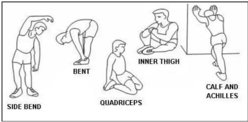
1. Warm-Up
To prevent injury and maximize performance we recommend that each workout period starts with a warm-up. We suggest you do the following exercise as the sketch map. Each exercise at least about 30 seconds.
Even though we go to great efforts to ensure the quality of each product we produce, occasional errors and/or omissions do occur. In any event should you find this product to has either a defective or a missing part, please contact us for a replacement.
Consumer service department: ABISAL Sp. z o. o.
ul. Św. Elżbiety 6
41–905 Bytom
serwis@abisal.pl
www.abisal.pl
www.hms-fitness.pl
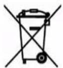
The equipment label depicting a crossed-out wheeled bin symbol informs that it is forbidden to dispose of waste electrical and electronic equipment together with other types of waste. In accordance with the WEE directive on waste electrical and electronic equipment, separate waste management processes should be
applied for this type of equipment. The user who intends to dispose of such a product is obliged to return it to an electronic equipment collection point thanks to which they can contribute to its re-use, recycling, and recovery and, in this way, protect the environment. To do this, contact the sales point where the equipment was purchased or a representative of the local authorities. Hazardous substances included in electronic equipment can have negative long-term influence on the natural environment and they can also have negative effect on human health.
RADY TÝKAJÍCÍ SE BEZPEČNOSTI
SCHÉMA
natural_image
Technical line drawing of a mechanical tool with a handle and spiral base (no text or symbols)5
82
66
4
88
42
6

7
89
87
| Číslo | Popis | Ks |
| 5 | T šroub (M8*77mm) | 1 |
| 82 | Šroub (ST3*16) | 2 |
| 66 | Podložka ( 8* 19*2T ) | 4 |
| 4 | Váleček ( 8* 12*42mmL ) | 1 |
| 88 | Klíč | 1 |
| 42 | Šroub (M8X72L) | 4 |
| 6 | Podložka ( 8* 14*2t ) | 1 |
| 7 | Pružinová podložka ( 8.5* 13.5*2.5t ) | 1 |
| 89 | Klíč 6mm*30mm*84mm | 1 |
| 87 | Klíč 13.15 | 1 |
PODROBNÝ SEZNAM DÍLŮ
natural_image
Line drawing of a stationary exercise bike with adjustable arms and control panel (no text or symbols)KROK 8: Napájecí adapter.
Počítač
Funkce
| TEIL-NR. | BESCHREIBUNG | MENGE |
| 1 | COMPUTER | 1 |
| 3 | VORDERE ABDECKUNG | 1 |
| 8 | LENKERSTÜTZROHR FÜR DEN COMPUTER | 1 |
| 9 | ABDECKUNG DES LENKERSTÜTZROHRS | 1 |
| 13 | SATTEL | 1 |
| 16 | SITZSTÜTZE | 1 |
| 21 | SATTELSTÜTZROHR | 1 |
| 28 | PEDAL (R) 9/16 '' | 1 |
| 43 | HINTERER STANDFUß | 1 |
| 44 | HAUPTRAHMEN | 1 |
| 58 | PEDAL (L) 9/16 '' | 1 |
| 62 | VORDERER STANDFUß | 1 |
| 67 | HINTERE ABDECKUNG | 1 |
| 79 | LENKER | 1 |
| 90 | NETZADAPTER | 1 |
| LISTE DER TEILE UND WERKZEUGE | 1 |
LISTE DER WERKZEUGE
natural_image
Simple line drawing of a mechanical tool with a handle and spring-like base (no text or symbols)5
82
natural_image
Four identical hand-drawn oval shapes with internal concentric rings, arranged in a 2x2 grid (no text or symbols)66
4
88
42
6

7
89
87
SCHRITT 5: Montage des Computers
SCHRITT 6: Montage des Lenkers
natural_image
Line drawing of a stationary exercise bike with attached resistance tester (no text or symbols)- The Seller provides guarantee on behalf of the Guarantor within the territory of the Republic of Poland for the period of 24 months from the date of sale.
- The Guarantee will be recognised by the shop or service centre after the client provides:
- clearly and correctly filled-in guarantee card with the sale stamp and
the seller's signature - valid purchase confirmation for the equipment
including the date of sale / bill / - complained product.
- Possible defects and damages revealed during the guarantee period shall be remedied free of charge within not more than 21 days from the delivery of the product to the shop or service.
- Should it be necessary to import some components, the guarantee term can be extended by the period required to import such part, however such period shall not be longer than 40 days.
-
The guarantee does not cover:
-
mechanical damages and subsequent defects,
- damages and defects resulting from incorrect storage and usage of the equipment against its purpose,- incorrect assembly and maintenance,
-
damages and consumption of such elements as: cables, straps, rubber parts, pedals, sponge grips, wheels, bearings, etc.
-
The guarantee expires in the event of:
-
expiry of the validity term,
- self-repairs,
-
failure to follow the rules of correct operation.
-
No duplicates of the guarantee cards shall be issued.
- The product handed over for repair should be complete and clean. If some parts are missing, the service is entitled to refuse to accept the product for repair. The service may refuse to accept a dirty product or clean in on the client's expense after the client's written permit.
- The guarantee does not cover activities related to assembly, maintenance, which, according to the instruction, the user is obliged to perform themselves.
- The Guarantor also informs that they offer post-guarantee service.
- The product should be provided in its original packaging and should be secured for shipment.
The guarantee for sold goods is not exclusive, does not limit or suspend entitlements of the buyer resulting from the non-compliance of the product with
the agreement.
Notes on the course of repairs
| Item | Date of notificacion | Date of provision | Course of repairs | Signature of the recipient (shop, owner) |
ZÁRUČNÍ LIST


- LISTA KONTROLNA PRZED MONTAZEM
- LISTA NARZĘDZI
- Instrukcja montażu
- KROK 1
- KOMPUTER
- FUNKCJE
- IMPORTANT SAFETY INFORMATION
- SPECIFICATIONS
- MAINTENANCE
- BREAKING
- Exploded drawing:
- PARTS LIST AND TOOLS
- PRE-ASSEMBLY CHECK LIST
- HARDWARE PARTS LIST
- Assembly instruction
- STEP 1
- STEP 1: Assemble front and rear stabilizer
- STEP 2
- STEP 2: Assemble seat
- STEP 3
- STEP 3: Assemble seat post
- STEP 4
- STEP 4: Assemble upright post
- STEP 5
- STEP 5: Assemble computer
- STEP 6
- STEP 6: Assemble handlebar
- STEP 7
- STEP 7: Assemble pedals
- COMPUTER
- FUNCTION
- FUNCTION DESCRIPTION
- RECOVERY
- KEY FUNCTIONS
- TIPS
- Cardio – Training:
- TRAINING INSTRUCTION
- Warm-Up
- RADY TÝKAJÍCÍ SE BEZPEČNOSTI
- SCHÉMA
- Počítač
- Funkce
- LISTE DER WERKZEUGE
- SCHRITT 5: Montage des Computers
- SCHRITT 6: Montage des Lenkers
- ZÁRUČNÍ LIST
Brand : HMS Premium
Model : M6995
Category : Home trainer