
M9239 - Home trainer HMS Premium - Free user manual and instructions
Find the device manual for free M9239 HMS Premium in PDF.


| Product Type | Magnetic resistance home trainer |
| Model | M9239 |
| Brand | HMS Premium |
| Dimensions (L x W x H) | Approx. 60 x 50 x 40 cm |
| Weight | Approx. 8 kg |
| Power Supply | Manual (no external power required) |
| Resistance Type | Magnetic, continuous adjustment |
| Resistance Levels | 8 levels |
| Bike Compatibility | 26"-28" rear wheel, quick release or thru-axle |
| Max User Weight | 120 kg |
| Flywheel Weight | 2.5 kg |
| Noise Level | Low (magnetic) |
| Display | Basic LCD: time, speed, distance, calories |
| Connectivity | None |
| Pedals Included | No (use your own bike) |
| Foldable | Yes, for storage |
| Transport Wheels | Yes, on front leg |
| Frame Material | Steel with powder coating |
| Color | Black/Gray |
| Maintenance | Clean with damp cloth; lubricate moving parts annually |
| Safety | Stable base; secure bike attachment; follow instructions |
| Spare Parts | Resistance unit, skewer, mat, repair kit available |
| Warranty | 2 years |
Frequently Asked Questions - M9239 HMS Premium
User questions about M9239 HMS Premium
0 question about this device. Answer the ones you know or ask your own.
Ask a new question about this device
Download the instructions for your Home trainer in PDF format for free! Find your manual M9239 - HMS Premium and take your electronic device back in hand. On this page are published all the documents necessary for the use of your device. M9239 by HMS Premium.
USER MANUAL M9239 HMS Premium
natural_image
Line drawing of a stationary exercise bike with adjustable arms and legs (no text or symbols)UWAGI DOTYCZĄCE BEZPIECZEŃSTWA
6. Montaż siodelka
natural_image
Line drawing of a person performing a stationary exercise on a scooter (no text or symbols)IMPORTANT SAFETY INFORMATION
This product has been designed for home use only and built for optimum safety. Please note the following safety precautions:
-
Before starting any exercise program you should consult your doctor to determine if you have any physical or health conditions that could create a risk to your health and safety, or prevent you from using the equipment properly. Your doctor's advice is essential if you are taking medication that affects your heart rate, blood pressure or cholesterol level. This is especially important for persons over the age of 35, pregnant women, or those with pre-existing health problems or balance impairments.
-
Before using this equipment to exercise, always do stretching exercises to properly warm up.
-
Be aware of your body's signals. Incorrect or excessive exercise can damage your health. Stop exercising if you experience any of the following symptoms: pain, tightness in your chest, irregular heartbeat, extreme shortness of breath, feeling light headed, dizzy or nauseous. If you do experience any of these conditions you should consult your doctor before continuing with exercise program. Injuries to health may result from incorrect or excessive training.
-
During exercises and after keep children and pets away from the equipment.
-
Use the equipment on a stable and levelled surface with a protective cover for your floor or carpet. Move all sharp objects.
-
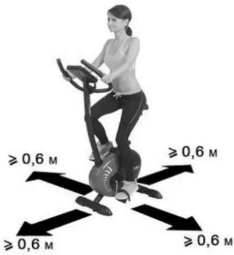
Free area shall be not less than 0,6 m greater than the training area in the directions from which the equipment is accessed. Free area must also include the area for emergency dismount. Where equipment is positioned adjacent to each other the value of the free area may be shared.
-
Before each use, visually inspect the unit including hardware and resistance bends.
-
Before using the equipment, check if the nuts, bolts and other bends are securely tightened.
-
Always use the equipment as indicated. If you find any defective components whilst assembling or checking the equipment, or if you hear any unusual noise coming from the equipment while using, stop. Do not use the equipment until the problem has been rectified.
-
Do not insert any object into any openings.
-
Be aware of all regulation and constructions parts which may disturb during exercises.
-
The safety level of the equipment can only be maintained if it is regularly examined for damage and/or wear and tear.
-
Wear suitable clothing whilst using the equipment. Avoid wearing loose clothing which may get caught in the equipment or that may restrict or prevent movement.
-
The equipment has been tested and certified according to EN ISO 20957-1 under class H. It is not suitable for therapeutic use.
-
Care must be taken when lifting or moving the equipment so as not to injure your back. Always use proper lifting techniques and/or use assistance.
-
The equipment is designed for adult use only. Keep unsupervised children away from the equipment.
-
Assemble this unit as described in this manual. Use only parts from the set. Check all parts with the part list.
WARNING: READ ALL INSTRUCTIONS BEFORE USING ANY FITNESS EQUIPMENT. WE ASSUME NO RESPONSIBILITY FOR PERSONAL INJURY OR PROPERTY DAMAGE CAUSED BY OR THROUGH THE USE OF THIS PRODUCT
SPECIFICATIONS
Weight - 24,5 kg
Flywheel - 9 kg
Dimensions - 93 x 54,5 x 128,5 cm
Maximum weight of user - 120 kg
MAINTENANCE
Your unit has been carefully designed to require minimum maintenance. To ensure this, we recommend that you do the following:
• Always make sure that the bands are secure and show no signs of wear
• Regularly check the tightness of nuts and bolts
- Keep your unit clean by wiping sweat, dust or other residue off with a soft, clean cloth after each use
SADDLE ADJUSTMENT
Loosen seat post screw. Set height according to growth. Tighten up screw. Do not take out seat post from the main frame.
TENSION ADJUSTMENT
To reduce tension turn control into sign "-" direction, to increase tension turn control into sign "+" direction.
BREAKING
Stop to pedal when you want stop the item. Magnetic bike M9239 Prime HMS not acquire breaking system or emergency break.
PARTS LIST AND TOOLS
| Description | Qty | No. | Description | Qty | |
| 1 | Rear stabilizer | 1 | 41 | 8-section tension control | 1 |
| 2 | Adjustable foot | 2 | 42 | M8×16 Bolt | 4 |
| 3 | Triangle base foot cap | 4 | 43 | M6×8 Bolt | 2 |
| 4 | Main frame | 1 | 44 | Crosshead bolt M5×35 | 1 |
| 5 | Front stabilizer | 1 | 45 | Hole pulg | 2 |
| 6 | Front cover | 1 | 46 | Crosshead self bolt ST2.9×8 | 2 |
| 7 | Handlebar support | 1 | 47 | Crosshead self bolt ST4.2×16 | 8 |
| 8 | Handlebar | 1 | 48 | Round M8×40 Bolt | 1 |
| 9 | Φ25 Ball plug | 2 | 49 | Half round bolt M8*20 | 4 |
| 10 | Foam grip | 2 | 50 | Spring spacer | 8 |
| 11 | Computer | 1 | 51 | Crosshead self bolt ST4.2×20 | 9 |
| 12 | Sensor | 2 | 52 | M6 Nut | 1 |
| 13 | Front plastic cover | 1 | 53 | Extra-thin small hexagon nut | 3 |
| 14 | Seat cushion tube cover | 1 | 54 | Fine-thread thin hexagonal nut | 3 |
| 15 | Φ6 Flat washer | 3 | 55 | Φ8 Flat washer | 9 |
| 16 | Seat bracket | 1 | 56 | Roller axis | 2 |
| 17 | Computer wire (down) | 1 | 57 | Φ5 Flat washer | 1 |
| 18 | Computer wire (up) | 1 | 58 | Stopping flat washe | 2 |
| 19 | Pulse wire | 2 | 59 | Nylon nut M8 | 5 |
| 20 | Seat cushion | 1 | 60 | Nylon nut M6 | 1 |
| 21 | Right cover | 1 | 61 | Magnetic guider | 1 |
| 22 | Left cover | 1 | 62 | Seat cushion adjustable bracket | 1 |
| 23 | Crank | 1 | 63 | End cap F35 | 2 |
| 24 | Belt wheel | 1 | 64 | Short knob | 1 |
| 25 | Foot wheel | 2 | 65 | Φ6 Elasticity washer | 2 |
| 26 | D-shaped plastic cover | 1 | 66 | Pin | 1 |
| 27 | Spring knob | 1 | 67 | Pedal strap | 2 |
| 28 | Bearing set | 1set | 68 | Wire bracket | 1 |
| 29 | Pressing wheel bracket | 1 | 69 | Handlebar Plastic cover | 1 |
| 30 | Pressing belt wheel | 1 | 70 | Spacer | 1 |
| 31 | M10×60 Bolt | 1 | 71 | T-knob | 1 |
| 32 | 4V Belt | 1 | 72 | Crank spacer | 2 |
| 33 | Flywheel | 1 | 73 | Thin flat washerΦ6 | 1 |
| 34 | Arc washer | 4 | 74 | Crosshead bolt M5×10 | 1 |
| 35 | Spacer | 1 | 75 | Cover fixing ring | 1 |
| 36 | Flywheel axis | 1 | 76 | Crosshead self bolt ST2.2×10 | 1 |
| 37 | Magnetic guider bracket | 1 | 78 | M10 Nut | 1 |
| 38 | Tension control wire | 1 | 79 | Screw driver S=5 | 1 |
| 39 | Magnetic spring | 1 | 77 | Crosshead bolt M6×20 | 1 |
| 40 | Pedal(Left & Right) | 2 | 80 | Wrench | 1 |
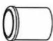
(26)D-shaped plastic cover 1pc
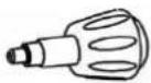
(27)Spring knob 1pc

(34) Arc washer 4pcs

(42) M8X16 Bolt 4pcs

(45)Hole plug 1pc
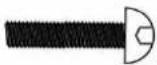
(49) M8X20 Bolt 4pcs
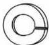
(50) 8 Spring washer
8pcs

(55)Φ8 Flat washer 4pcs
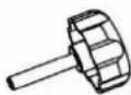
(64) Short knob 1pc
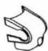
(69) Plastic cover 1pc

(70) Spacer 1pc
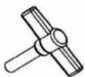
(71) T-knob 1pc
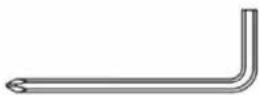
(79) Screwdriver 1pc
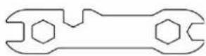
(80) Wrench 1pc
ASSEMBLY INSTRUCTION
1) Attach the Front Stabilizer
Attach the Front stabilizer (5) to the Main frame (4) with two M8*20 bolt (49), Φ8 Flat washer(55) and Φ8 spring washer(50).(Refer figure 1)
2) Attach the Rear Stabilizer
Attach the Rear stabilizer (1) to the Main frame (4) with 2 sets of M8*20 bolt(49), Φ8 Spring washer (50) and Φ8 flat washer (55). (Refer figure 2)
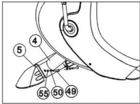
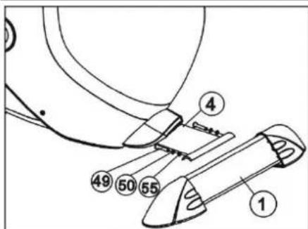
Figure2
3) Attach the Handlebar Support
a. Put the cable end of resistance cable of Tension control (41) into the spring hook of Tension control wire (38) as shown on drawing A of figure 3.
b. Pull the resistance cable of Tension control (41) up and force it into the gap of metal bracket of Tension control wire (38) as shown on drawing B of figure 3.
c. Connect the resistance cable of Tension control (41) with the Tension control wire (38) completed as shown on drawing C of figure 3.
d. Insert the Computer wire (17&18) through into the bottom of Handlebar support (7) and pull it out from the top hole of Handlebar support (7).
e. Insert the Handlebar support (7) to the Main frame (4) and secure it with four M8x16 Bolts (42), 8 Spring washer (50) and Arc washers (34). (Refer figure 3)
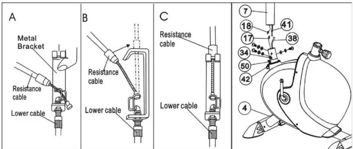
Figure 3
4) Attach the Handle Pulse Tube and Computer
a. Insert the Tension control wires (19) through into the hole of the Handlebar support (7) and then pull them out from the top hole of Handlebar support (7). Attach the Handlebar (8) to the Handlebar locator(A) of the Handlebar post(7) with the Handlebar cover(69), then insert the Tension control wires(19) into the hole of the Handlebar support(7) with the Pole plug(70), and put the Spacer(70) on the T-knob(71). Adjust the handlebar to the proper position, and lock with the T-knob(71) tightly.
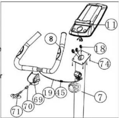
Figure 4
b. Connect the Computer wire (18) and the Pulse wires (19), insert the surplus wire into the Handlebar (7). Take Crosshead bolt M5×10 (74) from the computer (11), and use it fix the computer (11) to the top of handlebar support (7). (Refer figure 4)
Note: The latch of the handlebar (8) must be consistent with the groove of the handlebar support (7).
5) Attach the Seat cushion
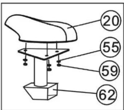
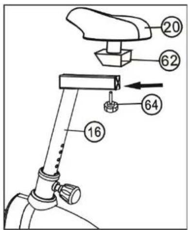
Attach seat cushion (20) to Seat cushion adjustable bracket (62) with three sets of Nylon nut M8 (59), 8 Flat washer (55) (Refer figure 5)
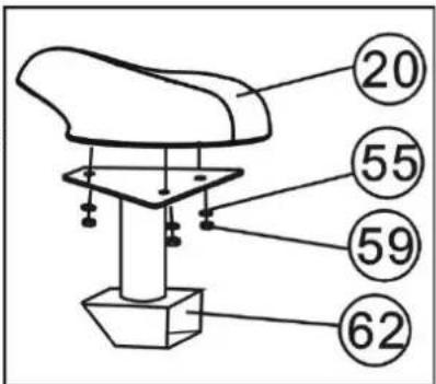
Figure 5
6) Attach the Seat Adjustor
First, remove three M8 Nylon Nuts (59) and 8 Flat washers (55) from underneath of the Seat cushion (20), and then attach the Seat cushion (20) to the Seat cushion adjustable bracket(62) with the three M8 Nylon Nuts (59) and 8 Flat washers (55) that were removed. (Refer figure 5)
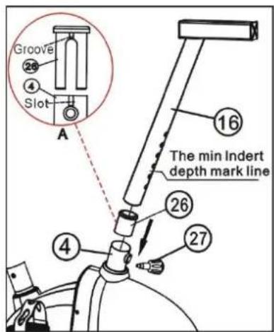
Take out D-shaped washer( below 26 mentioned parts ) from the hardware package, and with the groove of the D-shaped washer (26) aiming to the slot of the seat support of the main frame (4), pat the D-shaped washer (26) gently into the main frame (4), and then insert the Seat bracket (16) to the D-shaped washer (26) and the seat support of the main frame (4); insert the insert the Seat adjustor (16) into the hole (Refer figure 6). Finally, attach the Seat cushion adjustable bracket (62) to the top of Seat Adjustor (16) with short knob (64), adjust the saddle support plate to the appropriate position, and then tighten the short knob (64). (Refer figure 7)
7) Attach the Pedals
Tie the two Pedal strips (67) on the left & right Pedals (40), and then attach the left & right Pedals (40) to the Crank (23). (Refer figure 8)
NOTE: The left & right Pedals (40) and Crank (23) are marked with "L" & "R".
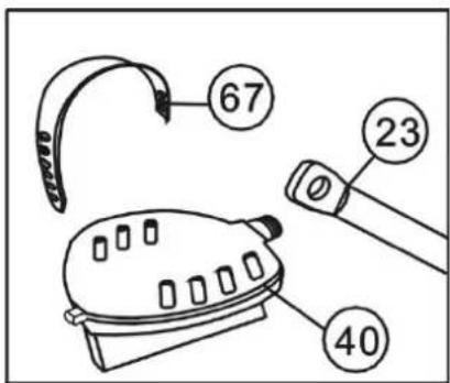
Figure 8
Instruction manual of M9239 Prime
Computer manual
BUTTONS
1. MODE
Press this button to changeover display or choose the window needs to be set.
2. RECOVERY / UP
I. In setting status, press this button to increase setting value in relevant flashing window for TIME, DIST, CAL and TEMP(°C or °F)
ii. In non-exercise or non-setting status, press this button to enter/exit pulse recovery function.
3. DOWN
In setting status, press this button to decrease setting value in relevant flashing window for TIME, DIST, CAL and TEMP(°C or °F)
4. RESET/GO
I. In setting status, press this button to reset the value in relevant flashing window for TIME, DIST and CAL.
ii. In parameters setting status for body fat, press this button to enter body fat test.
iii. In monitor status, hold this button for 3 seconds to reset all value to zero.
5. BODYFAT
In non-exercise status, press this button to enter/exit body fat parameters set-up.
FUNCTIONS
1. SPEED/BODYFAT RATIO/RPM(IF HAVE)
I. Display instantaneous speed and the range is 0.0\~99.9KM/H. If the monitor showing M, the range will be 0.0\~99.9MILE/H.
The max. pickup signal is 1500rpm.
ii. Display current repetition per minute(RPM) during exercise. It reflects the pedal frequency.
iii. Display Body fat ratio.
2. TIME/BMI
I. Count the total time from exercise start to the end and the range is 0 \~ 99M59S.
ii. Exercise time can be set in advance, when it approaches the preset time, the monitor will alarm 10 seconds before finish.
The maximum pre-set time is 99 minutes.
iii. Display Body Mass Index (BMI).
3.DISTANCE/BMR
I. Count the total distance from exercise start to the end and the range is 0.00 \~ 9.99 \~ 99.9KM. Or, if the meter showing M, the range will be 0.00 \~ 9.99 \~ 99.9 MILE.
ii. Exercise distance can be set in advance, when it approaches the preset distance, the monitor will alarm 10 seconds before finish. The maximum pre-set distance is 99.9KM or MILE(if the monitor showing M).
iii. Display Basal Metabolic Rate(BMR).
4. CALORIES/TEMPERATURE
I. Count the total calories consumed from exercise start to the end and the range is 0.0 \~ 99.9 \~ 999KCAL.
ii. The calorie value can be set in advance, when it approaches the preset calorie, the monitor will alarm 10 seconds before
finish.
iii. Display room temperature(TEMP).
5. PULSE
I. Measure the your heart rate per minute. The range is 40 \~ 240bpm.
ii. It will display "P" to pause the pulse test if there is no pulse signal over 60 seconds. You can press UP or DOWN to enter the pulse test again.
6. WHEEL DIAMETER
The wheel perimeter has been set according to client's requirements.
7. ALARM
The monitor will "Beep" when press "MODE" "RECOVERY/UP" "DOWN", RESET/GO or "BODYFAT" buttons.
8. AUTO ON/OFF & AUTO START/STOP
I. Without any signal of exercise or operation for 8 minutes, the power will turn off automatically and all the memory will be cleared off except body fat parameters and temperature.
ii. Once receive exercise or operation signal, the monitor will turn on automatically.
OPERATION
1. SET
Press MODE to choose the display window that needs to be pre-set, and the value in relevant window will flash. Then press UP/DOWN to increase/decrease the value to reach your want alarm time, alarm distance, or alarm calorie. Hold UP/DOWN to increase/decrease the value rapidly. Press RESET to reset value in relevant flashing window.
2. PULSE RATE
Before measuring your pulse rate, press any button to change "P" into "0" in the window, then enter pulse mode. Please place both your palms on the contact pads and the monitor will show your current heart beat rate in beats per minute (BPM) on the LCD after 3\~4 seconds.
3. PULSE RECOVERY
In non-setting and non-exercising status, first test your pulse as above mentioned. Then press RECOVERY/UP to enter pulse recovery function. The display will show 1 minute count-down as well as your pulse rate. Hold on the pulse sensor or wear the transmitter belt (IF HAVE) until it counts down to zero. Then, it will pop up your pulse recovery level from F1 to F6, that is, from the fastest recovery to slowest. The fastest recovery F1 show the best. Press RECOVERY/UP again to exit pulse recovery function.
4. BODYFAT, BMI & BMR
In non-exercising status, press BODYFAT to enter body fat parameters settings. You can set from the below sequence: exerciser No.(1 \~ 8), weight(KG), height(CM), age(YEAR), gender. But, if the meter showing M, the weight will show "lb", while height will show "in". Press MODE to proceed to next parameter setting. Press RECOVERY/UP to increase the setting value while press DOWN to decrease.
When you finish setting, hold the pulse sensor and press RESET/GO. Then the display will show your body fat in 6 seconds.
Press BODYFAT again to exit body fat test.
Remark:
I. During parameters setting, it will exit body fat test automatically if detects no operation signal over 10 seconds.
ii. During body fat test, it will display Er.1 if sense no test target over 10 seconds.
BODYFAT CONTRAST
| Gender/Age | Underweight | Healthy | Slightly Overweight | Overweight | Obese |
| Male/≤30 | <14% | 14%~20% | 20.1%~25% | 25.1%~35% | >35% |
| Male/>30 | <17% | 17%~23% | 23.1%~28% | 28.1%~38% | >38% |
| Female/≤30 | <17% | 17%~24% | 24.1%~30% | 30.1%~40% | >40% |
| Female/>30 | <20% | 20%~27% | 27.1%~33% | 33.1%~43% | >43% |
MP3(IF HAVE)
When the MP3 or cellphone connected with the input interface at the side of the computer by stereo plug, turn on the audio of the external service and put it to ON, if there's ON/OFF switch at the side of the computer, then, music playing. If no ON/OFF switch here, it will play music automatically.
BATTERY REPLACE
When the display becomes dim or illegible, remove the battery and replace them.
TERMS OF REFERENCES
Stationary bike exercises are replacing bicycle exercises. Magnetic bike M9239 Prime HMS is item class H. Unit is not intended for commercial use therapy or rehabilitation.
TRAINING INSTRUCTION
1. Warm-Up
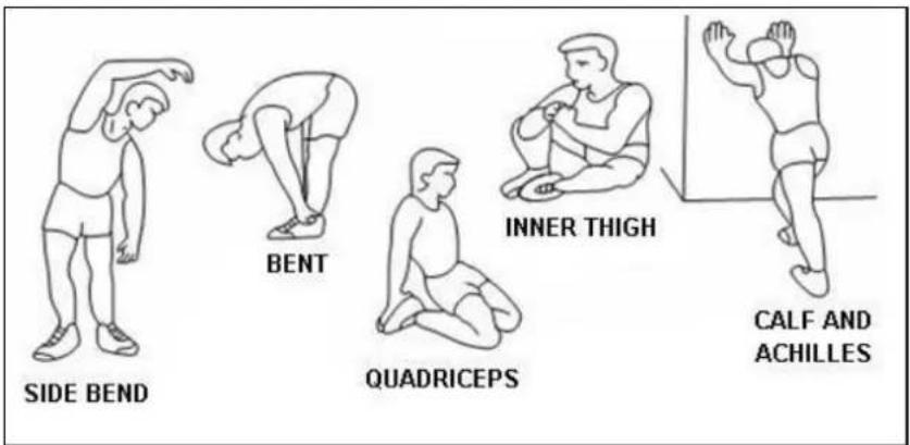
To prevent injury and maximize performance we recommend that each workout period starts with a warm-up. We suggest you do the following exercise as the sketch map. Each exercise at least about 30 seconds.
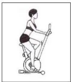
2. Position
Seat down at the saddle, put feet's in to pedals, hands put on the handlebar. Keep your back straight.
3. Training Organization
Warm-up:
Before every training you should warm-up for 5-10 minutes. Here you can do some stretching and training with low resistance.
natural_image
Line drawing of a person exercising on an exercise bike (no text or symbols)Training session:
During the actual training a rate of 70% -85% of the maximum pulse rate should be chosen. The time-length of your training session can be calculated with the following rule of thumb:
• daily training session: approx. 10 min. per unit
• 2-3 x per week: approx. 30 min. per unit
• 1-2 x per week: approx. 60 min. per unit
Cool down:
To introduce an effective cool-down of the muscles and the metabolism the intensity should be drastically decreased during the last 5 – 10 minutes. Stretching is also helpful for the prevention of muscle aches.
Success. Even after a short period of regular exercises you will notice that you constantly have to increase the resistance to reach your optimum pulse rate. The units will be continuously easier and you will feel a lot fitter during your normal day. For this achievement you should motivate yourself to exercise regularly. Choose fixed hours for your training session and do not start training too aggressively. An old quote amongst sportsmen says: "The most difficult thing about training is to start it."
Even though we go to great efforts to ensure the quality of each product we produce, occasional errors and/or omissions do occur. In any event should you find this product to has either a defective or a missing part, Please contact us for a replacement.
WARNING Heart rate monitoring systems may be inaccurate. Over exercising may result in serious injury or death. If you feel faint stop exercising immediately.
NÁVOD K OBSLUZE
RADY TÝKAJÍCÍ SE BEZPEČNOSTI
natural_image
Line drawing of a person performing a stationary exercise on a steamer (no text or symbols)Rozcvička:
CE
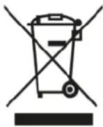
EN: Marking the equipment with a symbol of a crossed-out waste container informs about prohibition of placing used electrical and electronic equipment with other household waste. According to the WEEE Directive on used electrical and electronic waste management, separate disposal methods must be applied for this type of equipment. A user, who intends to dispose this product, is required to deliver it to a collection point for used electrical and electronic equipment in order to contribute to reuse, recycling, or recovery and consequently, to protect the environment. To do this, contact the point where the device was purchased or local government officials. Hazardous components contained in the electronic equipment can cause long-lasting adverse changes in the environment, as well as have a harmful effect on human health.
- The Seller, on behalf of the Guarantor, provides a guarantee in the territory of the Republic of Poland for a period of 24 months from the date of sale.
-
The guarantee will be honoured by the shop or service centre upon presentation by the customer:
-
a legibly and correctly completed warranty card with the sales stamp and the seller's signature,
- a valid proof of purchase of the equipment with the date of sale / receipt, the goods claimed.
- Any defects and damage discovered during the warranty period will be repaired free of charge within a maximum of 21 days from the date of delivery of the goods to the service.
- In the case of the necessity to import parts, the repair period may be extended by the time necessary for their import, but not longer than 90 days.
-
The warranty does not cover:
-
mechanical damage and defects caused by them,
- damages and defects resulting from improper use and storage,
- improper assembly and maintenance,
-
damage and wear of components such as cables, straps, rubber parts, pedals, sponge grips, wheels, bearings, etc.
-
The warranty is void in the event of:
- expiry date,
- self-repair,
- failure to observe the rules of correct operation.
- Product returned for repair should be complete and clean. In the case of defects the service has the right to refuse acceptance for repair. If the product is delivered dirty, the service centre may refuse to accept it or clean it at the customer's expense with his written consent.
- The warranty does not cover installation and maintenance work, which, according to the user manual, must be carried out by the user himself.
- The guarantor also informs that it provides post-warranty service.
- The goods should be protected for shipping.
- In order to make use of the warranty, please follow the procedure on the website: https://serwis.abisal.pl/.
In case of non-conformity of the sold thing with the contract, the buyer is entitled by law to legal remedies from and at the expense of the seller. The guarantee does not affect such remedies.
THE EQUIPMENT IS NOT INTENDED FOR REHABILITATION AND THERAPY
NOTES ON THE COURSE OF REPAIRS
| Item | Date of notification | Date of provision | Course of repairs | Signature of the recipient (shop, owner) |
ZÁRUČNÍ LIST
HMS-FITNESS.COM

IMPORTER: ABISAL SP. Z O.O., ul. Pyskowicka 17, 41-807 Zabrze, Polska
DISTRIBUTOR: ABISTORE SPORT S.R.O, U Cihelny 230/3, 74801 Hlučín, Česká Republika
abisal@abisal.pl www.abisal.pl


- UWAGI DOTYCZĄCE BEZPIECZEŃSTWA
- Montaż siodelka
- IMPORTANT SAFETY INFORMATION
- SPECIFICATIONS
- MAINTENANCE
- SADDLE ADJUSTMENT
- TENSION ADJUSTMENT
- BREAKING
- ASSEMBLY INSTRUCTION
- 1) Attach the Front Stabilizer
- 2) Attach the Rear Stabilizer
- 3) Attach the Handlebar Support
- 4) Attach the Handle Pulse Tube and Computer
- 5) Attach the Seat cushion
- 6) Attach the Seat Adjustor
- 7) Attach the Pedals
- Instruction manual of M9239 Prime
- BUTTONS
- MODE
- RECOVERY / UP
- DOWN
- RESET/GO
- BODYFAT
- FUNCTIONS
- SPEED/BODYFAT RATIO/RPM(IF HAVE)
- TIME/BMI
- 3.DISTANCE/BMR
- CALORIES/TEMPERATURE
- PULSE
- ALARM
- AUTO ON/OFF & AUTO START/STOP
- OPERATION
- SET
- PULSE RATE
- PULSE RECOVERY
- BODYFAT, BMI & BMR
- Remark:
- BODYFAT CONTRAST
- MP3(IF HAVE)
- BATTERY REPLACE
- TERMS OF REFERENCES
- TRAINING INSTRUCTION
- Warm-Up
- Position
- Training Organization
- Warm-up:
- Training session:
- Cool down:
- NÁVOD K OBSLUZE
- RADY TÝKAJÍCÍ SE BEZPEČNOSTI
- Rozcvička:
- THE EQUIPMENT IS NOT INTENDED FOR REHABILITATION AND THERAPY
- ZÁRUČNÍ LIST
Brand : HMS Premium
Model : M9239
Category : Home trainer