EPL 12-7 BE - Drill Narex - Free user manual and instructions
Find the device manual for free EPL 12-7 BE Narex in PDF.


| Product Type | Drill |
| Brand | Narex |
| Model | EPL 12-7 BE |
| Power Input | 700 W |
| Supply Voltage | 230 V ~ 50 Hz |
| No-Load Speed | 0 - 2700 rpm |
| Max. Drilling Diameter (Steel) | 12 mm |
| Max. Drilling Diameter (Wood) | 30 mm |
| Chuck Type | Keyless |
| Chuck Capacity | 1.5 - 13 mm |
| Weight | 1.8 kg |
| Power Cord Length | 2.5 m |
| Protection Class | II (Double Insulated) |
| Variable Speed | Yes (trigger-controlled) |
| Reverse Function | Yes |
| Safety Clutch | Yes |
| Side Handle Included | Yes |
| Depth Stop Included | Yes |
| Carbon Brushes | Replaceable |
| Maintenance | Clean ventilation slots regularly; check brushes after 100 hours |
Frequently Asked Questions - EPL 12-7 BE Narex
User questions about EPL 12-7 BE Narex
0 question about this device. Answer the ones you know or ask your own.
Ask a new question about this device
Download the instructions for your Drill in PDF format for free! Find your manual EPL 12-7 BE - Narex and take your electronic device back in hand. On this page are published all the documents necessary for the use of your device. EPL 12-7 BE by Narex.
USER MANUAL EPL 12-7 BE Narex
Original operating manual (EN) 17
natural_image
Exterior view of a gray EPL 12-7 BE power tool (no signage or text on body)Symboly použité v návodu a na stroji Symboly použité v návode a na stroji Symbols used in the manual and on the machine Símbolos y su significado Изображение и описание пиктограмм Symbole užate w instrukcji i na maszynie A kezelési utasításban és a gépen használt jelzések

1
Figure and description of pictograms
1 Warning of general danger!
2 Caution! Read this manual to reduce the injury hazard!
3 Double insulation
4 Not to be included in municipal refuse!
5 Used safety glasses!



natural_image
Line drawing of a mechanical device with a downward arrow indicating force or movement (no text or symbols present)Narex s.r.o.
Narex s.r.o.
Original operating manual (EN)
Table of contents
| Machine Description | 17 |
| Preface to the Operating Manual | 17 |
| Technical Data | 17 |
| General Power Tool Safety Warnings | 18 |
| Safety Instructions for Saws with Linear Reciprocating Motion | 18 |
| Information about noise level and vibrations | 18 |
| Double insulation | 18 |
| Scope of Use | 19 |
| Saw Blade Clamping and Removal | 19 |
| Splinter Guard | 19 |
| Chip / Sawdust Guard | 19 |
| Sawdust Extraction | 19 |
| Cut Parameter Setting | 19 |
| Putting into Operation and Operation | 20 |
| Work Instructions | 20 |
| Accessories | 20 |
| Maintenance and service | 20 |
| Storage | 20 |
| Environmental protection | 20 |
| Warranty | 21 |
| EC Certificate of Conformity | 21 |
Machine Description
| 1......Clamping lever |
| 2......Saw blade clamp |
| 3......Saw blade |
| 4......Additional saw blade guide |
| 5......Additional guide set screw |
| 6......Splinter guard |
| 7......Jig saw base runner |
| 8......Base runner pad |
| 9......Splinter guard locking nose |
| 10......Chip guard |
| 11......Extraction channel |
| 12......Extraction adapter |
| 13......Extraction hole |
| 14......Extraction adapter lock |
| 15......Extraction adapter lock retaining groove |
| 16......Base runner set screw |
| 17......Hexagonal (Allen) wrench |
| 18......Base runner slope scale |
| 19......Pendulum stroke change over switch |
| 20......Guide bell |
| 21......Rod |
| 22......Stroke controller |
| 23......Switch button |
| 24......Switch lock button |
| 25......Centering base runner pin |
| 26......Centering base runner hole |
| 27......Guide for straight cuts |
| 28......Guide for circular cuts (circle cutter) |
| 29......Clamping clip for the guide |
| 30......Parallel guide stop |
| 31......Guide locking screw |
| 32......Hole for the circle cutter pin |
| 33......Circle cutter pin |
| 34......Steel base runner pad |
| 35......Vent holes |
The displayed or described accessories do not necessarily become the integral part of jig saw delivery.
Preface to the Operating Manual
This Operating Manual shall facilitate familiarization with the device and with its correct applications. The Operating Manual contains important instructions how to handle the device safely, professionally and economically, thus avoiding risks, minimizing repairs and outage time and increasing its reliability and service life. The Operating Manual must be available continuously on the place where the device is used. The Operating Manual must be read and observed by all persons authorized to work with the machine, e.g. to operate, maintain or transport it. Besides the Operating Manual and the mandatory regulations how to avoid injury, valid in the country where the device is used, it is also necessary to observe the generally accepted technical rules for safe and professional work as well as the injury prevention rules of relevant professional associations.
Technical Data
| Type EPL 12-7 BE | |
| Rated voltage (V) 230–240 | |
| Power frequency (Hz) 50–60 | |
| Rated power input (W) 720 | |
| Number of strokes in idle cycle ( min^-1 ) 1,000–2,900 | |
| Electronic stroke number selection | √ |
| Pendulum stroke setting 4 stages | |
| Hoisting (mm) 26 | |
| Cut-through in timber (mm) 120 | |
| in colour metals (mm) 20 | |
| in steel (mm) | 10 |
| Chamfer cuts | ± 45^ |
| Quick coupling blade system FastFix* | √ |
| Weight (kg) | 2.4 |
| Protection class | II / ☑ |
| * System of tool-less circular-saw blade clamping | |
General Power Tool Safety Warnings

WARNING! Read all safety warnings and all instructions. Failure to follow the warnings and instructions may result in electric shock, fire and/or serious injury.
Save all warnings and instructions for future reference!
The term "power tool" in the warnings refers to your mains-operated (corded) power tool or battery-operated (cordless) power tool.
1) Work area safety
a) Keep work area clean and well lit. Cluttered or dark areas invite accidents.
b) Do not operate power tools in explosive atmospheres, such as in the presence of flammable liquids, gases or dust. Power tools create sparks which may ignite the dust or fumes.
c) Keep children and bystanders away while operating a power tool. Distractions can cause you to lose control.
2) Electrical safety
a) Power tool plugs must match the outlet. Never modify the plug in any way. Do not use any adapter plugs with earthed (grounded) power tools. Unmodified plugs and matching outlets will reduce risk of electric shock.
b) Avoid body contact with earthed or grounded surfaces, such as pipes, radiators, ranges and refrigerators. There is an increased risk of electric shock if your body is earthed or grounded.
c) Do not expose power tools to rain or wet conditions. Water entering a power tool will increase the risk of electric shock.
d) Do not abuse the cord. Never use the cord for carrying, pulling or unplugging the power tool. Keep cord away from heat, oil, sharp edges or moving parts. Damaged or entangled cords increase the risk of electric shock.
e) When operating a power tool outdoors, use an extension cord suitable for outdoor use. Use of a cord suitable for outdoor use reduces the risk of electric shock.
f) If operating a power tool in a damp location is unavoidable, use a residual current device (RCD) protected supply. Use of an RCD reduces the risk of electric shock.
3) Personal safety
a) Stay alert, watch what you are doing and use common sense when operating a power tool. Do not use a power tool while you are tired or under the influence of drugs, alcohol or medication. A moment of inattention while operating power tools may result in serious personal injury.
b) Use personal protective equipment. Always wear eye protection. Protective equipment such as dust mask, non-skid safety shoes, hard hat, or hearing protection used for appropriate conditions will reduce personal injuries.
c) Prevent unintentional starting. Ensure the switch is in the off-position before connecting to power source and/or battery pack, picking up or carrying the tool. Carrying power tools with your finger on the switch or energising power tools that have the switch on invites accidents.
d) Remove any adjusting key or wrench before turning the power tool on. A wrench or a key left attached to a rotating part of the power tool may result in personal injury.
e) Do not overreach. Keep proper footing and balance at all times. This enables better control of the power tool in unexpected situations.
f) Dress properly. Do not wear loose clothing or jewellery. Keep your hair, clothing and gloves away from moving parts. Loose clothes, jewellery or long hair can be caught in moving parts.
g) If devices are provided for the connection of dust extraction and collection facilities, ensure these are connected and properly used. Use of dust collection can reduce dust-related hazards.
4) Power tool use and care
a) Do not force the power tool. Use the correct power tool for your application. The correct power tool will do the job better and safer at the rate for which it was designed.
b) Do not use the power tool if the switch does not turn it on and off. Any power tool that cannot be controlled with the switch is dangerous and must be repaired.
c) Disconnect the plug from the power source and/or the battery pack from the power tool before making any adjustments, changing accessories, or storing power tools. Such preventive
safety measures reduce the risk of starting the power tool accidentally.
d) Store idle power tools out of the reach of children and do not allow persons unfamiliar with the power tool or these instructions to operate the power tool. Power tools are dangerous in the hands of untrained users.
e) Maintain power tools. Check for misalignment or binding of moving parts, breakage of parts and any other condition that may affect the power tool's operation. If damaged, have the power tool repaired before use. Many accidents are caused by poorly maintained power tools.
f) Keep cutting tools sharp and clean. Properly maintained cutting tools with sharp cutting edges are less likely to bind and are easier to control..
g) Use the power tool, accessories and tool bits etc. in accordance with these instructions, taking into account the working conditions and the work to be performed. Use of the power tool for operations different from those intended could result in a hazardous situation.
5) Service
a) Have your power tool serviced by a qualified repair person using only identical replacement parts. This will ensure that the safety of the power tool is maintained.
Safety Instructions for Saws with Linear Reciprocating Motion
- During activities where the cutting tool may touch hidden cabling or its own lead, the power tool must be held by the insulated gripping surfaces. The cutting tool coming into contact with a live conductor may cause metal parts of the power tool to become live as well and cause injury by electric current to the user.
- Use clamps or other practical method of securing and propping up the workpiece on a stable base. Holding the workpiece by hand or propped up against the body leads to its instability and can cause the user to lose control of the tool.
Information about noise level and vibrations
The values have been measured in conformity with EN 62841-1:
Acoustic pressure level L_nA = 82.6 dB (A)
Acoustic power level L_w,a = 93.5 dB (A)
In accuracy of measurements K = 1.5 dB (A)

ATTENTION! Noise is generated during work! Use ear protection!
Vibration emission value a_h (vector sum for three directions) and uncertainty K measured in accordance with EN 62841:
Sawing wood a_hB = 3.28 m/s^2
In accuracy of measurements K = 0.65 m/s ^2
Sawing metal a_hM = 3.76 m/s^2
In accuracy of measurements K = 0.65 m/s²
The emission values specified (vibration, noise) were measured in accordance with the test conditions stipulated in EN 62841 and are intended for machine comparisons. They are also used for making preliminary estimates regarding vibration and noise loads during operation.
The emission values specified refer to the main applications for which the power tool is used. If the electric power tool is used for other applications, with other tools or is not maintained sufficiently prior to operation, however, the vibration and noise load may be higher when the tool is used.
Take into account any machine idling times and downtimes to estimate these values more accurately for a specified time period. This may significantly reduce the load during the machine operating period.
Double insulation
To ensure maximum safety of the user, our tools are designed and built to satisfy applicable European standards (EN standards). Tools with double insulation are marked by the international symbol of a double square. These tools must not be grounded and a two-wire cable is sufficient to supply them with power. Tools are shielded in accordance with EN 55014.
Scope of Use
The jig saws are designed and intended for shaped and direct cutting of wood, plastics, steel, non-ferrous metals, aluminium and ceramics. They are suitable for straight and arc cuts under the angle of ±45^ . Use the saw blades recommended by the manufacturer for the operations above.
The user is responsible for improper use.
Saw Blade Clamping and Removal

ATTENTION! Risk of el. shock. Prior to start any operation, pull the plug out of the socket!
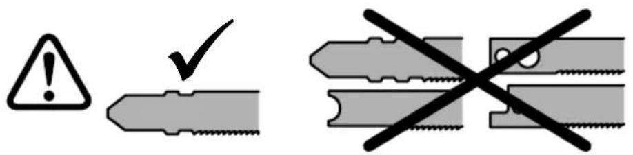
To clamp the saw blade (3), tilt the clamping lever (1) fully by one hand and insert the saw blade (3) by the second hand as far as the stop of the saw blade clamp (2). Then release the clamping lever (1) and move it to the initial position. (The clamping lever is equipped by a spring ensuring its tilting towards the jig saw body).
To remove the saw blade (3), tilt the clamping lever (1) fully by one hand and remove the saw blade (3) by the second hand (3) out of the saw blade clamp (2). If a new saw blade is not inserted, release the clamping lever and move it back to the initial position.
Saw blade guide setting (4)
For better guidance of the saw blade (3) the jig saw is equipped by the additional hard metal guide (4) mounted immediately above the workpiece.
Using the Allen key (internal part of the scope of delivery), screw or unscrew the additional guide set screw (5) until the guide jaws (4) nearly rest against the saw blade (3).
The saw blade clearance must guarantee its easy movement!
Splinter Guard
The splinted guard (6) allows cuts with splinter-free edges even on the side of the cut material which the saw blade base runner (7) leans against (except special saw blades with inverse saw teeth).

ATTENTION! Risk of injury in case of unwanted start of the tool. Prior to start any operation, pull the plug out of the socket!
☐ Insert the splinter guard (6) into the base runner pad (8) and push it as far as the saw blade. Attention, the locking nose (9) in the side groove of the splinter guard (6) must be up with respect to the position of the jig saw base runner (7).
☐ Set the pendulum stroke (see the chapter "Pendulum Stroke Setting") to position 1 or 2.
☐ Start the jig saw (see the chapter "Putting into Operation").
Place the jig saw by its protruding splinter guard (6) against a firm support (e.g. the desk edge, etc.) and push the jig saw moderately to the cut so that the splinter guard (6) may be cut partially in order to align the front splinter guard edge with the front jig saw base runner edge.
□ Stop the jig saw.
The splinter guard (6) must lie close to the saw blade on both sides to ensure reliable function of the splinter guard! Thus, a new splinter guard (6) should be fitted every time the saw blade is changed to ensure splinter-free cuts.
Chip / Sawdust Guard
The chip guard (10) prevents chips from flying off into the cut zone and improves efficiency of the chip extractor operation.

ATTENTION! Risk of injury in case of unwanted start of the tool. Prior to start any operation, pull the plug out of the socket!
☐ Insert the chip guard (10) between the jig saw base runner (7) and the saw blade clamping lever (1).
☐ Push the chip guard moderately until it leans against the jig saw base runner and body (the chip guard "catches" in place).
☐ Remove the chip guard (10) by separating both guard ends from the jig saw base runner (7) (by your fingers) and by simultaneous pushing the guard out of the jig saw.
Sawdust Extraction

ATTENTION! Dust can he hazardous to human health and therefore newer work without the dust extractor, mainly in closed rooms.
When extracting hazardous dust, always observe the valid national regulations.
When extracting dust (chips, sawdust) by the industrial vacuum cleaner, observe the operating manual of the used vacuum cleaner!
When extracting the dust, do use the splinter guard (6) to avoid extraction channel (11) clogging.
☐ Insert the extraction adapter (12) into the extraction hole (13) on the rear jig saw base runner side (7) so that the extraction adapter lock (14) may be engaged into the locking groove (15) inside the jig saw base runner.
☐ Place the vacuum cleaner (extractor) suction hose (hose diameter 27 mm) on the extraction adapter extension (12).
☐ Disconnect the extraction adapter (12) from the jig saw by pressing the extraction adapter lock (14) in the locking groove (15) and by simultaneous taking the adapter out of the extraction hole (13).
Cut Parameter Setting

ATTENTION! Risk of injury in case of unwanted start of the tool. Prior to start any operation, pull the plug out of the socket!
Setting for oblique cuts
The jig saw base runner (7) can be swivelled to both sides by 45^ in the longitudinal axis.
☐ Remove the chip guard (10) and the splinter guard (6) from the jig saw, when mounted.
☐ Loosen the set screw (16) with internal hexagon on the bottom jig saw base runner side (7), using the Allen key (17).
☐ Move the jig saw base runner (7) forwards (by ca 5 mm) a and set the requested angle in accordance with the scale (18) on the jig saw base runner.
☐ Tighten the set screw (16).
Longitudinal base runner movement
The jig saw base runner (7) can be moved by ca 5 mm in the longitudinal axis.
The basic jig saw base runner (7) position: the runner is moved backwards fully, i.e. the centering pin (25) is pushed into the centering hole (26).
☐ Loosen the set screw (16) with internal hexagon on the bottom jig saw base runner side (7), using the Allen key (17).
☐ Move the jig saw base runner (7) to the requested position.
☐ Then tighten the set screw (16).
Attention! If the splinter guard (6) was mounted on the jig saw base runner in the front position, the sprinter guard will have to be cut in additionally!
Pendulum stroke setting
The pendulum stroke is generated by horizontal movement of the guide bell (20), synchronously with rod (21) movement up and down. When moving downwards, the saw blade is put further away from the material. This way the chip can be taken out of the cut, heat generation by friction reduced and saw blade service life extended.
The pendulum stroke parameters can be set by the pendulum stroke switch (19) in four steps 0–3, if the switch is in position 0 the pendulum stroke is off and in the position 3 the pendulum stroke reaches its maximum.
Instructions for setting:
Set the zero pendulum stroke when machining thin materials like sheet metal or hard materials, e.g. ceramic.
Setting of low or zero pendulum stroke guarantees better cut edges of soft materials.
Higher pendulum stroke can be applied mainly for soft materials, e.g. wood and plastics.
When cutting curves or arcs in soft materials, set the zero or low pendulum stroke (depending on the curvature size) to reduce the saw blade stress in cut.
Suitable pendulum stroke setting can be verified by a test cut. Rough
English
data for pendulum stroke setting are contained in the table Values of setting of the number of strokes and the pendulum stroke.
Setting of the number of strokes
Using the stroke controller (22), you can pre-select the necessary number of strokes on the run.
1-2 Low number of strokes
3-4 Medium number of strokes
5–6 High number of strokes
The necessary number of strokes depends on the kind of material and can be established by a practical test. Rough data for setting of the number of strokes are contained in the table Values of setting of the number of strokes and the pendulum stroke.
After a longer work with low number of strokes let the jig saw run at the max. number of strokes (degree 6) for at least 1 to 3 minutes to let the jig saw motor cool.
Table: Values of setting of the number of strokes and the pendulum stroke
| Material | Max. material strength | Number of strokes | Forward swinging |
| Timber 120 mm 6 | 1–3 | ||
| Steel 10 mm 2–4 | 0–1 | ||
| Aluminium 20 mm | 3–5 0–2 | ||
| Plastic material | 20 mm 3–6 0–2 | ||
| Rubber 30 mm 1–2 | 0 | ||
| Ceramics 10 mm | 3–5 0 |
Putting into Operation and Operation
Check whether the data on the rating plate match with the real power supply voltage. The tool intended for 230 V\~ may be also connected to 220/240 V\~. Check whether the plug type corresponds to the socket type.
Start and stop
Press the switch button (23) to start the jig saw. Release the switch button to stop the tool.
Continuous run
Press the switch button (23) as far as the stop and at the same time depress the lock button (24). The switch button will thus be locked in the ON position, i.e. the jig saw will run continuously. Release the switch button.
By re-pressing the switch button (23), the lock button (24) will be unlocked and after release of the switch button the jig saw will be stopped.
Work Instructions

ATTENTION! Risk of injury. Secure the workpiece to avoid its movement while being machined!
Use sharp saw blades intended for the relevant material. Adapt the number of strokes and the pendulum stroke to the material. When cutting metal, coat the cut zone by a suitable lubricant to avoid saw blade overheating.
Take care of uniform saw blade movement to the cut.
When the jig saw is switched off, do not brake the saw blade (3) by swivelling the jig saw to the sides!
Free jig saw guide by the scribe mark
The triangular pin on the splinter guard (6) shows the saw blade (3) guide line. Guiding the jig saw by the scribe mark is thus facilitated.
Jig saw cutting without pre-drilling
For plunge cuts in timber materials the jig saw base runner (7) must be in the front position (see the chapter Cut Parameter Setting).
☐ Place the jig saw by the front base runner edge on the material, where the saw blade will be plunged into.
☐ Plunge the saw blade slowly into the material at full speed and pendulum stroke preset to the max. value (position 3).

ATTENTION! Proceed carefully, because the saw blade can be bent and/or broken and fly off, thus causing serious injury!
Accessories
Guide for straight cuts/parallel guide (27)
(Optional accessories)
Use the parallel guide to guide the jig saw parallel to the workpiece edge. The parallel guide can be fitted on any side of the jig saw base runner (7).
☐ Slide the clamping clip (29) onto the base runner from the front.
☐ Insert the parallel guide (27) from the requested side into the clamping clip hole and set the requested position which shall be measured from the saw blade to the parallel guide stop (30).
☐ Tighten both locking screws (31) of the clamping clip.
Attention! Prior to mounting the parallel guide, the chip guard (10) must fixed, if it shall be used!
Guide for circular cuts (circle cutter) (28)
(Optional accessories)
The circle cutter can be used to produce circular cuts with the diameter ranging from 120 to 720 mm. The circle cutter can be fitted on any side of the jig saw base runner (7).
☐ Slide the clamping clip(29) onto the base runner from the front.
☐ Insert the circle cutter (28) from the requested side into the clamping clip hole and set the requested position which shall be measured from the saw blade to the centre of the rear hole for the circle cutter pin (32).
☐ Tighten both locking screws (31) of the clamping clip.
☐ Insert the circle cutter pin (33) into the rear circle cutter hole.
Steel base runner pad
The manufacturer inserts the plastic base runner pad (8) on the jig-saw base runner. The pad slides smoothly on the wooden and plastic materials, thus restricting occurrence of scratches on the cut material.
The steel base runner pad (34) is suitable for use on all other materials.
☐ To replace the base runner pad, it is necessary to unscrew six screws on the bottom side of the jig saw base runner (7).
☐ Take out the base runner pad (8) and replace it for the requested one.
☐ Screw all six screws on the bottom side of the jig saw base runner and tighten carefully.
Maintenance and service

ATTENTION! Risk of el. shock. Prior to start any operation, pull the plug out of the socket!
Jig saw vent holes (35) may not be clogged. Clean them regularly, preferably by compressed air. When cutting conductive material, the jig saw must be cleaned carefully. Blow the vent holes by the compressed air in the rear jig saw part where the motor is mounted.
Lubricate the rod (21) and the guide bell (20) by a few drops of oil from time to time.

ATTENTION! With respect to protection from el. shock and preservation of the class of protection, all maintenance and service operations requesting jig saw case removal must be performed by the authorized service centre only!
The current list of authorized service centres can be found at our website www.narex.cz, section "Service Centres".
Storage
Packed appliance may be stored in dry, unheated storage place with temperature not lower than -5 °C.
Unpacked appliance should be stored only in dry storage place with temperature not lower than +5 °C with exclusion of all sudden temperature changes.
Environmental protection
Power tools, accessories and packaging should be sorted for environmental-friendly recy.
Only for EU countries:
Do not dispose of power tools into household waste!
According to the European Directive 2002/96/EC on waste electrical and electronic equipment and its incorporation into national law, power
tools that are no longer suitable for must be separately collected and sent for recovery in an environmental-friendly manner.
Warranty
Our equipment is under warranty for at least 12 months with regard to material or production faults in accordance with national legislation. In the EU countries, the warranty period for exclusively private use is 24 months (an invoice or delivery note is required as proof of purchase).
Damage resulting from, in particular, normal wear and tear, overloading, improper handling, or caused by the user or other damage caused by not following the operating instructions, or any fault acknowledged at the time of purchase, is not covered by the warranty.
Complaints will only be acknowledged if the equipment has not been dismantled before being sent back to the suppliers or to an authorised NAREX customer support workshop. Store the operating instructions, safety notes, spare parts list and proof of purchase in a safe place. In addition, the manufacturer's current warranty conditions apply.
EC Certifi cate of Conformity
We declare that this device meets requirements of the following standards and regulations.
Safety
EN 62841-1; EN 62841-2-11
Directive 2006/42/EC
Electromagnetic compatibility
EN 55014-1; EN 55014-2; EN 61000-3-2;
EN 61000-3-3; EN 61000-6-3
Directive 2014/30/EU
RoHS
Directive 2011/65/EU
Place of storage of the technical documentation:
Narex s.r.o.
470 01 Česká Lípa CEO of the company
May 1, 2020
Directiva 2006/42/EC
Apoderado
01-05-2020
Narex s.r.o.
Chelčického 1932 Mацией Стайковски 470 01 Česká Lípa (Maciej Stajkowski)
Поверенный в делах
01.05.2020 г.
компании
Narex s.r.o.
Narex s.r.o.
The current list of authorized service centres can be found at our website www.narex.cz, section "Service Centres".
- Symboly použité v návodu a na stroji Symboly použité v návode a na stroji Symbols used in the manual and on the machine Símbolos y su significado Изображение и описание пиктограмм Symbole užate w instrukcji i na maszynie A kezelési utasításban és a gépen használt jelzések
- Figure and description of pictograms
- Original operating manual (EN)
- Preface to the Operating Manual
- General Power Tool Safety Warnings
- Save all warnings and instructions for future reference!
- Safety Instructions for Saws with Linear Reciprocating Motion
- Information about noise level and vibrations
- ATTENTION! Noise is generated during work! Use ear protection!
- Double insulation
- Scope of Use
- Saw Blade Clamping and Removal
- ATTENTION! Risk of el. shock. Prior to start any operation, pull the plug out of the socket!
- Saw blade guide setting (4)
- Splinter Guard
- ATTENTION! Risk of injury in case of unwanted start of the tool. Prior to start any operation, pull the plug out of the socket!
- Chip / Sawdust Guard
- Sawdust Extraction
- ATTENTION! Dust can he hazardous to human health and therefore newer work without the dust extractor, mainly in closed rooms.
- Cut Parameter Setting
- Setting for oblique cuts
- Longitudinal base runner movement
- Attention! If the splinter guard (6) was mounted on the jig saw base runner in the front position, the sprinter guard will have to be cut in additionally!
- Pendulum stroke setting
- Instructions for setting:
- English
- Setting of the number of strokes
- Putting into Operation and Operation
- Start and stop
- Continuous run
- Work Instructions
- ATTENTION! Risk of injury. Secure the workpiece to avoid its movement while being machined!
- Free jig saw guide by the scribe mark
- Jig saw cutting without pre-drilling
- ATTENTION! Proceed carefully, because the saw blade can be bent and/or broken and fly off, thus causing serious injury!
- Accessories
- Guide for straight cuts/parallel guide (27)
- Guide for circular cuts (circle cutter) (28)
- Steel base runner pad
- Maintenance and service
- ATTENTION! With respect to protection from el. shock and preservation of the class of protection, all maintenance and service operations requesting jig saw case removal must be performed by the authorized service centre only!
- Storage
- Environmental protection
- Only for EU countries:
- Warranty
- EC Certifi cate of Conformity
- Safety
- Electromagnetic compatibility
- RoHS
Brand : Narex
Model : EPL 12-7 BE
Category : Drill