
GT35 - Brush cutter Cocraft - Free user manual and instructions
Find the device manual for free GT35 Cocraft in PDF.


| Brand | Cocraft |
| Model | GT35 |
| Product Type | Electric brush cutter (grass trimmer) |
| Power Source | Mains powered (corded) |
| Voltage | 220–240 V AC, 50 Hz |
| Power | 350 W |
| No-Load Speed | 10,000 rpm |
| Cutting Diameter | 250 mm |
| Line Diameter | 1.5 mm |
| Weight | 2.7 kg (model 18-4583) or 2.3 kg (model 31-1324) |
| Noise Level (LpA) | 82 dB(A), K=3 dB |
| Noise Level (LwA) | 93 dB(A), K=3 dB |
| Vibration (Rear Handle) | 6.531 m/s², K=1.5 m/s² |
| Vibration (Front Handle) | 6.764 m/s², K=1.5 m/s² |
| Shaft Type | Telescopic, adjustable length |
| Trimmer Head Adjustment | 5 fixed angle positions; 3 fixed rotation positions |
| Additional Features | Edging wheel, safety guard, cable restraint, safety switch trigger |
| Line Replacement | Spool system with spring, line diameter 1.5 mm |
| Safety Certifications | Compliant with Machinery Directive 2006/42/EC, EMC, Low Voltage Directive |
| Intended Use | Trimming grass and edging in household gardens |
Frequently Asked Questions - GT35 Cocraft
User questions about GT35 Cocraft
0 question about this device. Answer the ones you know or ask your own.
Ask a new question about this device
Download the instructions for your Brush cutter in PDF format for free! Find your manual GT35 - Cocraft and take your electronic device back in hand. On this page are published all the documents necessary for the use of your device. GT35 by Cocraft.
USER MANUAL GT35 Cocraft
natural_image
Blue and black industrial cleaning brush head with visible branding (no text or symbols)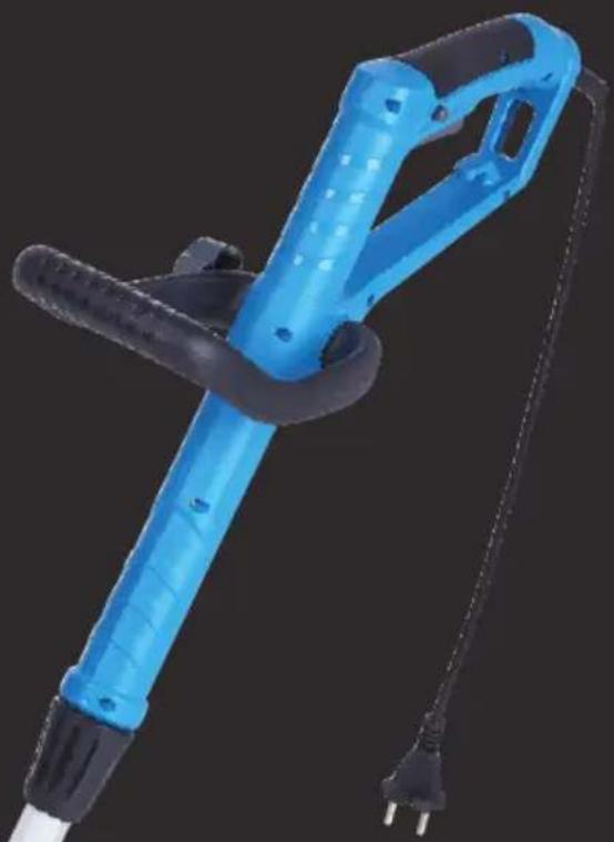
natural_image
Blue handheld electric shaver with black handle and power plug, isolated on dark background (no text or symbols)
Important!
Read the entire instruction manual carefully and make sure that you fully understand it before you use the equipment. Keep the manual for future reference.
Viktig information:
Original instructions
Bruksanvisning i original
Originalbruksanvisning
Please read the entire instruction manual before using the product and then save it for future reference. We reserve the right for any errors in text or images and any necessary changes made to technical data. If you have any questions concerning technical problems please contact our Customer Services.
Contents
Safety....4
General Safety Requirements 4
Specific Safety Instructions for Grass Trimmers 6
Grass trimmer symbol explanation....7
Product description......8
Assembly 9
Front handle 9
Safety guard 9
Edging wheel....10
Operating instructions 10
Setup....10
Connecting the extension lead 11
Switching the trimmer on....11
Care and maintenance....11
Changing the trimmer line 11
Disposal....13
Specifications 13
Safety
General Safety Requirements
General safety instructions for power tools
Warning: Read all the instructions. Failure to adhere to the following instructions may lead to electric shocks, fires or serious injuries.
SAVE THESE INSTRUCTIONS.
The term “power tools” in the warning text below refers to your handheld mains operated or battery operated tool.
1) Work area
a) Keep the work area clean and well illuminated. Cluttered and poorly lit areas invite accidents.
b) Do not use power tools in explosive environments, e.g. near to flammable liquids, gases or dust. Power tools generate sparks that can easily ignite dust or fumes.
c) Keep children and other bystanders away from the area where you are using the power tool. Distractions can cause you to lose concentration and control of the tool.
2) Electrical safety
a) The power tool plug must fit correctly into the wall socket. Never modify the plug in any way. Never use an adaptor together with earthed power tools. Unmodified plugs and suitable wall sockets minimize the risk of electric shocks.
b) Avoid physical contact with earthed objects such as pipes, radiators, ovens and refrigerators. There is an increased risk of receiving an electrical shock if your body is earthed.
c) Do not expose the power tool to rain or other wet conditions. Water entering a power tool will increase the risk of electric shock.
d) Do not abuse the mains lead. Never use the lead to carry the tool or pull the plug from a wall socket. Keep the lead away from heat, oil, sharp edges and moving parts. Damaged or tangled leads increase the risk of electric shock.
e) When using power tools outdoors, use an extension lead that is suitable for this purpose. The use of an extension lead designed for outdoor use decreases the risk of electric shocks.
f) If the use of the power tool in a wet environment is unavoidable, a wall socket equipped with a residual current device (RCD) should be used. Use of an RCD significantly reduces the risk of electric shock.
3) Personal safety
a) Pay attention to what you are doing and use common sense when using power tools. Never use power tools if you are tired or under the influence of drugs, alcohol or medication. One moment of inattention while using a power tool may result in a serious injury.
b) Wear protective clothing. Always wear safety glasses. Using protective clothing such as dust masks, non-slip safety shoes, helmets and ear defenders reduces the risk of injury.
c) Avoid accidental starts. Make sure that the power switch is set to OFF before plugging the power tool into a wall socket, picking up or carrying the power tool. Never carry a power tool with your finger on the trigger and never connect the power tool to a wall socket when the switch is set to ON, since it may result in injury.
d) Remove all service tools/keys before switching on the power tool. A service tool left on a rotating part of the power tool may result in personal injury.
e) Do not overreach. Keep proper footing and balance at all times. This ensures better control over the power tool in unexpected situations.
f) Wear suitable clothing. Do not wear loose-fitting clothing or jewellery. Keep hair, clothes and gloves away from moving parts. Loose-fitting clothes, jewellery or long hair could become caught in moving parts.
4) Use and maintenance of the power tool
a) Do not force the power tool. Use the correct power tool for your application. The correct power tool will perform the task better and safer if used at the correct feed rate.
b) Never use the power tool if the power switch does not switch the tool on and off. Any power tool that cannot be controlled by the power switch is dangerous and must be repaired.
c) Unplug the lead from the wall socket before making any adjustments, changing accessories or storing the power tool. These precautions reduce the risk of the power tool starting unexpectedly.
d) Store power tools that are not being used out of children's reach. Do not allow people who are unfamiliar with the tool or these instructions to operate the tool. Power tools can be dangerous if they fall into the hands of inexperienced users.
e) Maintaining power tools. Check for any incorrect settings, parts that catch, broken parts or anything else which may cause the power tool to malfunction. If something is damaged it must be repaired before use. Many accidents are caused by poorly maintained power tools.
f) Keep cutting tools sharp and clean. Properly maintained cutting tools with sharp cutting edges are less likely to bind and are easier to control.
g) Use the power tool, and any accessories in accordance with these instructions, taking into account the working conditions and the work to be performed. Using the power tool for a purpose other than that for which it is intended could result in a dangerous situation.
5) Service
a) Repairs and service should only be performed by qualified tradesmen, and only with original spare parts. This guarantees that the safety of the power tool is maintained.
Specific Safety Instructions for Grass Trimmers
- This grass trimmer is not intended for use by persons (including children) with reduced physical, sensory or mental capabilities, or lack of experience and knowledge, unless they have been given supervision or instruction concerning the safe use of the grass trimmer by a person responsible for their safety.
- Never let children operate or play with the grass trimmer. Keep it out of reach of children.
- Wear sturdy footwear, long trousers, safety glasses and gloves.
- Keep anyone standing close by at a safe distance from the grass trimmer.
- Keep children and pets out of the work area. Stones and other debris can be ejected by the grass trimmer. Switch the grass trimmer off immediately should any onlookers, adults, children or pets, come within 5 metres.
- Only use the grass trimmer in good light conditions.
- If the grass trimmer has been subjected to any shocks or impacts it must be checked for damage. Any defect or damage must be repaired before the grass trimmer is used. Make sure the trimmer head is securely fastened on. If it is loose or damaged the grass trimmer must not be used.
• Always inspect the grass trimmer before use. - The safety guard must always be fitted before the grass trimmer is used. The grass trimmer must not be used if the safety guard is damaged or missing.
- Before starting to use the grass trimmer, check the area to be trimmed for foreign objects such as stones or cables.
• Always hold the grass trimmer firmly. Hold it in both hands. - Never attach metal cutting blades to this grass trimmer.
- Keep the ventilation openings of the trimmer head free from debris. Remove any grass or leaves.
- The blade will continue to rotate after the motor has been turned off. Wait until the blade has completely stopped before servicing.
- The grass trimmer must not be exposed to rain or moisture.
- Make sure that you are familiar with all the controls and settings before using the grass trimmer.
- Keep hands and feet away from the trimmer head and line at all times and especially when switching the motor on.
-
Be careful when adjusting the trimmer line; do not switch the motor on until you are holding the grass trimmer in the correct way.
-
Only use the grass trimmer with parts and accessories recommended by the manufacturer.
- Keep proper footing and balance at all times.
- Avoid directing the trimmer head towards immovable objects when the trimmer head is spinning, as they could damage the grass trimmer.
- Do not attempt to stop the trimmer head with hands or feet, let it stop by itself.
- Avoid operating the grass trimmer on gravel paths, gravel covered yards or other places where stones could be ejected.
Grass trimmer symbol explanation

Warning! Grass trimmers can be dangerous.

Read the instruction manual.

Do not expose the grass trimmer to rain or moisture.

Wear eye protection.
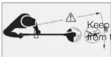
Keep all persons and animals at a safe distance from the grass trimmer.
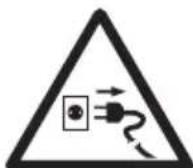
Unplug the mains lead from the electrical socket immediately if it is damaged.
Product description
The picture shows the assembled grass trimmer, parts 2 and 3 are not attached when sold.
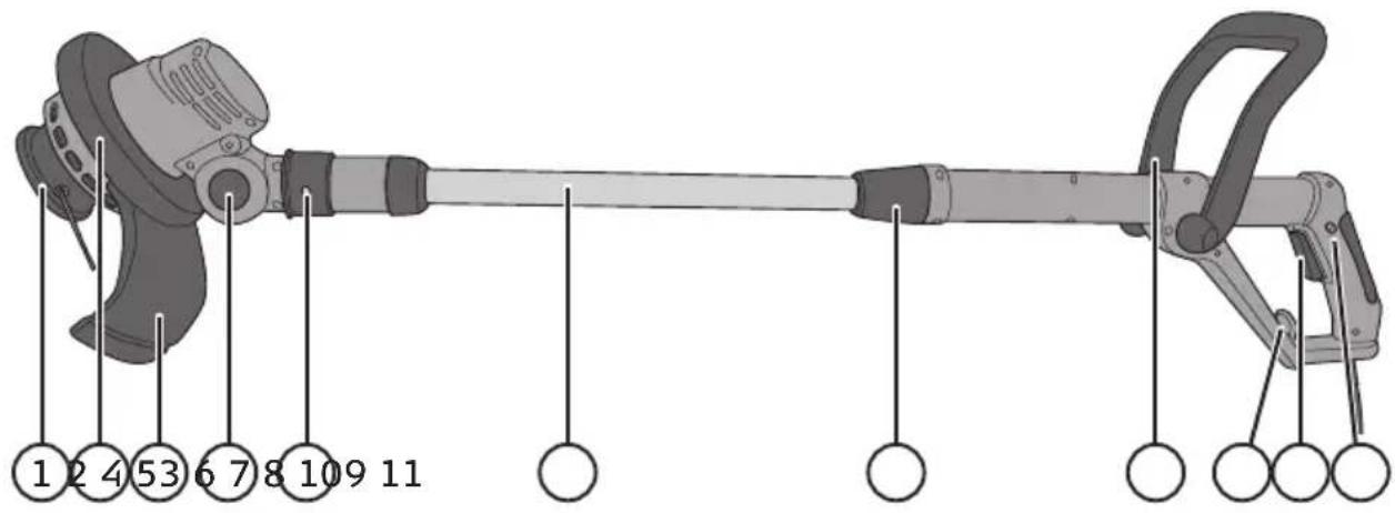
- Trimmer head
- Edging wheel
- Safety guard
- Release button for adjusting the trimmer head angle to one of its 5 fixed positions
- Catch for twisting the trimmer head to one of its 3 fixed positions. Push the catch forward towards the trimmer head.
- Telescopic handle
- Locking knob for adjusting the length of the telescopic shaft. Twist clockwise to unlock and anticlockwise to lock.
- Adjustable front handle
- Cable restraint
- [⏻] Trigger
- Safety switch for preventing unintentional operation. Hold the button in before pulling the trigger.
Assembly
Note: Do not connect the grass trimmer to an electrical socket until it is completely assembled.
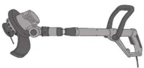
Note: When sold, the grass trimmer shaft is contracted to enable it to fit into the box. The first time the telescopic shaft is extended, it passes a non-return pawl creating a new end-stop. The shaft will then only be able to contract as far as the new end-stop.
natural_image
Illustration of a mechanical power tool with a shank and lever mechanism (no text or symbols)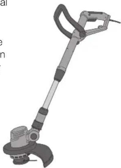
natural_image
Illustration of a metal tool with a power shank and lever mechanism (no text or symbols)Retracted when sold Max retracted length once having
been extended
Front handle
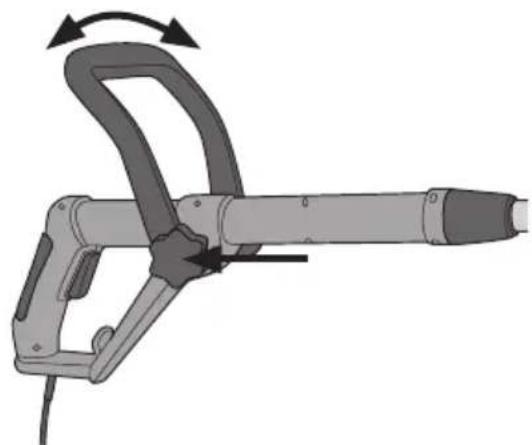
- Attach the front handle to the shaft. The handle can be mounted so that it leans forwards or backwards.
- Tighten the handle locking knob.
Safety guard
- Push the safety guard (3) into the groove in the trimmer head (1).
- Fasten the safety guard to the trimmer head using the included screw.
Note: Handle the guard carefully; it has a very sharp blade on it (indicated by the arrow).
natural_image
Illustration of a handheld tool with directional arrows indicating motion (no text or symbols)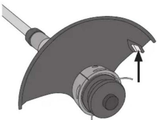
natural_image
Mechanical component diagram showing a curved mechanical assembly with a tool and directional arrow (no text or symbols)Edging wheel
The grass trimmer comes with an edging wheel (2). It consists of two parts which click together to surround the trimmer head. It is used for trimming edges.
Operating instructions Setup
-
Adjust the length of the telescopic shaft (6) to suit your height. Twist the locking knob (7) clockwise to release the shaft, adjust the length and then twist the locking knob anticlockwise to tighten.
-
Adjust the angle of the trimmer head by holding in the button (4) and moving the head to one of the 5 settings. Release the button when the trimmer head is at the desired setting.
-
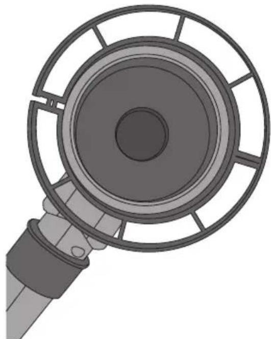
The trimmer head can be rotated and set to one of 3 fixed settings. Slide the spring-loaded catch (5) forward towards the trimmer head, twist the trimmer head into one of its fixed settings and then release the catch.
natural_image
Top-down view of a mechanical device with a circular component and radial slots (no text or symbols visible)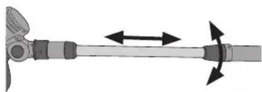
natural_image
Diagram of a propeller blade with bidirectional arrows indicating rotation (no text or symbols)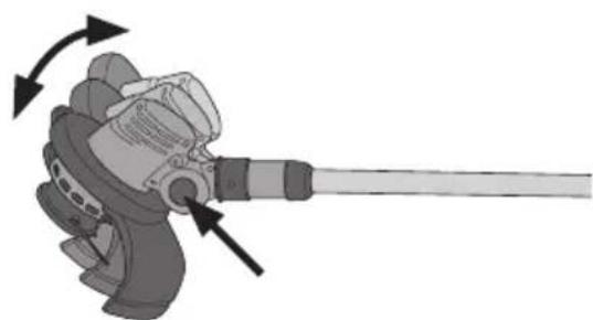
natural_image
Mechanical component diagram showing a lever with directional arrows indicating motion (no text or symbols)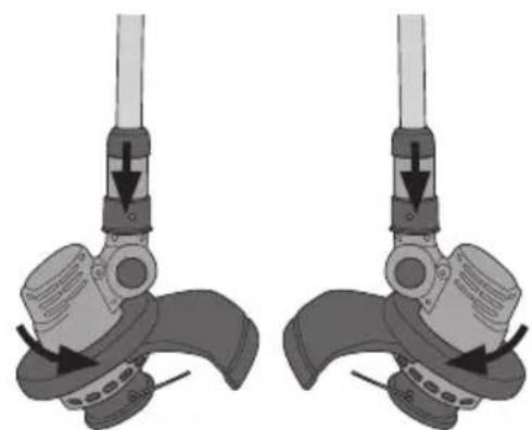
natural_image
Mechanical assembly diagram showing two identical configurations of a valve or clamp mechanism (no text or symbols present)Connecting the extension lead
- Make sure that the extension lead is not connected to the mains.
- Make a loop out of 20–25 cm of the extension lead and attach it to the cable restraint (9) on the handle.
- Tighten the loop over the cable restraint (9).
- Plug the grass trimmer lead into the extension lead.
- Plug the extension lead into a wall outlet when it is time to use the trimmer.
Switching the trimmer on
- Hold down the safety switch (11) on the rear handle.
- Start the trimmer by pressing in the power trigger (10).
- Release the power trigger to stop the motor.
Care and maintenance
Note: Always disconnect the plug from the power supply before cleaning, adjusting or transporting the grass trimmer.
Changing the trimmer line
natural_image
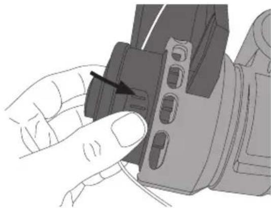
Close-up of a hand inserting a component into a mechanical housing (no text or symbols visible)- Remove the cover of the trimmer head by pressing in the two release catches (one on each side). Remove the line spool. Take care not to lose the spring located under the spool.
natural_image
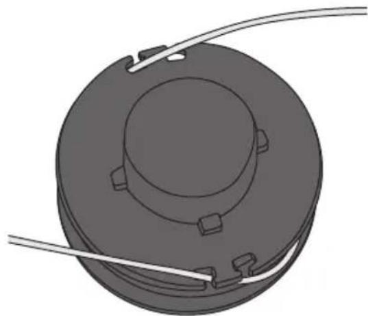
3D rendering of a circular mechanical component with mounting holes and a central hub, connected by two thin wires (no text or symbols)- Take a new spool and line and make sure that the line passes through the notches in the spool and that the ends of the line stick out about 15 cm to make fitting easier.
natural_image
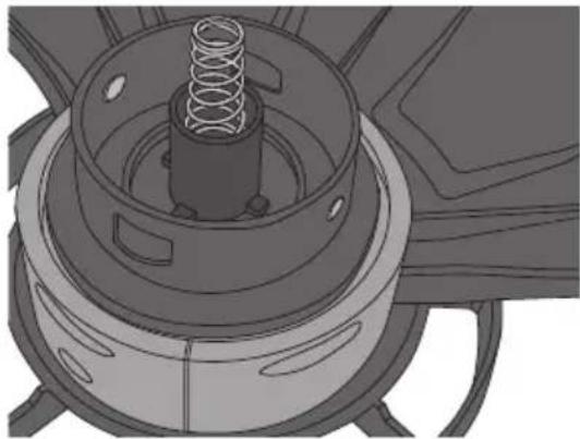
Mechanical assembly diagram showing a spring-loaded component mounted on a housing (no text or symbols visible)- Place the spring in the trimmer head with the wider end at the bottom of the cylinder and the narrow end pointing up towards the spool.
natural_image
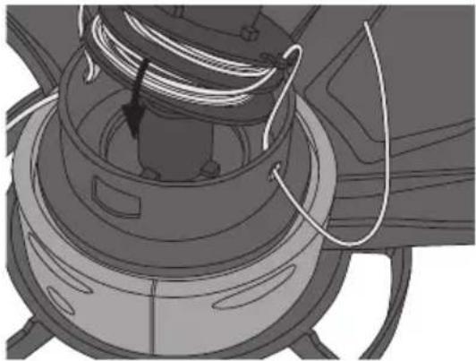
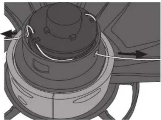
Mechanical assembly diagram showing a motor or generator with coiled cable and housing (no text or symbols)- Thread the ends of the line through the holes in the side of the trimmer head and place the spool on top of the spring in the trimmer head.
natural_image
Mechanical component diagram showing a cylindrical housing with internal components and directional arrows indicating motion (no text or symbols)- Pull gently on the ends of the line so that it comes out of the notches in the spool.
natural_image
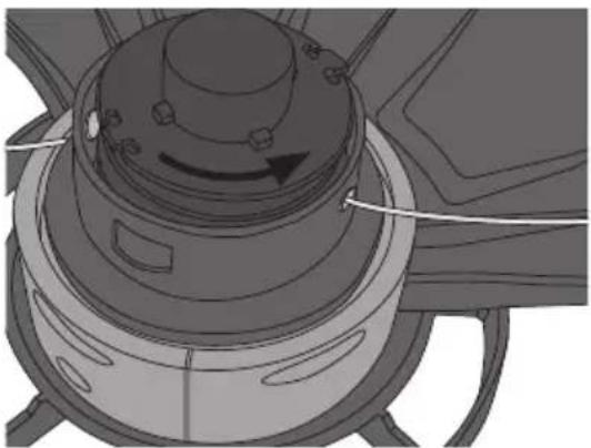
Mechanical component diagram showing a rotating knob and housing (no text or symbols)-
If there is an unnecessary length of line protruding from the spool, turn the spool anticlockwise to wind the line back onto the spool until only about 5–6 cm of line sticks out.
-
Refit the trimmer head cover making sure that the two catches spring out and lock it in place.
Note: Wear safety glasses and make sure that there are no bystanders nearby when starting the grass trimmer after new line has been fitted because any excess cut off line will fly out at high speed.
- Check regularly to ensure that no grass and twigs have built up around the spindle.
- Check before each use that the power trigger and safety catches are undamaged and work correctly.
- Clean the exterior of the trimmer with a soft brush or cloth, do not use water, solvents or polish.
- Regularly remove all dirt, especially from around the motor ventilation slits on the trimmer head.
- Store the grass trimmer in a safe, dry place out of the reach of children.
Responsible disposal
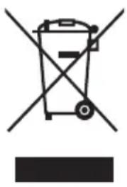
This symbol indicates that this product should not be disposed of with general household waste. This applies throughout the entire EU. In order to prevent any harm to the environment or health hazards caused by incorrect waste disposal, the product must be handed in for recycling so that the material can be disposed of in a responsible manner. When recycling your product, take it to your local collection facility or contact the place of purchase. They will ensure that the product is disposed of in an environmentally sound manner.
natural_image
Symbol of a trash bin crossed with no text or numbers, accompanied by a blank rectangular block below (no text or symbols present)Specifications
Voltage 220–240 V AC, 50 Hz
Power 350 W
No-load speed 10,000 rpm
Cutting diameter 250 mm
Line diameter 1.5 mm
Noise level LpA 82 dB(A), K: 3 dB
LwA 93 dB(A) K: 3 dB
Vibration Rear handle 6.531 m/s ^2 , K: 1.5 m/s ^2
Front handle 6.764 m/s ^2 , K: 1.5 m/s ^2
Weight 18-4583: 2.7 kg
31-1324: 2.3 kg
Grästrimmer 350 W
natural_image
Illustration of a mechanical power tool with a central blade and handle (no text or symbols)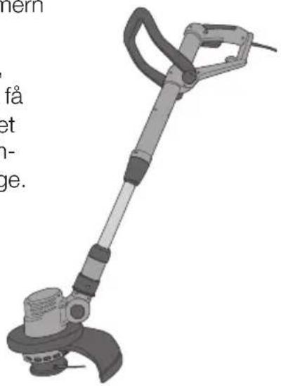
natural_image
Illustration of a metal detector device with no visible text or symbolsnatural_image
Illustration of a handheld tool with directional arrows indicating motion (no text or symbols)Skydd
natural_image
Mechanical component diagram showing a curved housing with a shaft and internal gear, no text or symbols presentStödhjul
natural_image
Top-down view of a mechanical device with a circular component and handle (no text or symbols visible)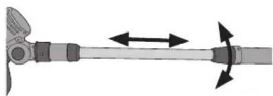
natural_image
Diagram of a mechanical lever with bidirectional arrows indicating motion (no text or symbols)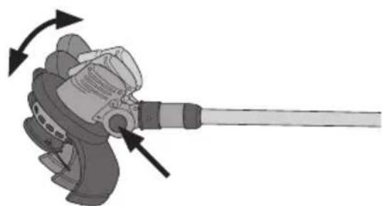
natural_image
Mechanical component diagram showing a lever mechanism with directional arrows indicating motion (no text or symbols)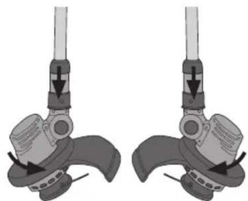
natural_image
Mechanical assembly diagram showing two identical configurations of a device with lever and adjustment arrows (no text or symbols)natural_image
Hand inserting a component into a device (no text or symbols visible)natural_image
3D rendering of a mechanical component with circular base and protruding wires (no text or symbols)natural_image
Mechanical component diagram showing a spring assembly inside a housing (no text or symbols)natural_image
Mechanical assembly diagram showing a coiled spring mounted on a cylindrical housing (no text or symbols visible)natural_image
Mechanical component diagram showing a cylindrical housing with internal components and directional arrows indicating motion (no text or symbols)natural_image
Mechanical component diagram showing a rotating knob and housing (no text or symbols)natural_image
Symbol of a trash bin crossed with no text or labels, accompanied by a black rectangular block below (no text or symbols present)Specifikationer
Drivspänning 220–240 V AC, 50 Hz
Effekt 350 W
Varvtal obelastad 10000 v/min
Klippdiameter 250 mm
Tråddiameter 1,5 mm
Ljudnivå LpA 82 dB(A), K: 3 dB
LwA 93 dB(A), K: 3 dB
Vibration Bakre handtag 6,531 m/s², K: 1,5 m/s²
Främre handtag 6,764 m/s², K: 1,5 m/s²
Vikt 18-4583: 2,7 kg
31-1324: 2,3 kg
Gresstrimmer, 350 W
Art.nr. 18-4583 Modell GT102 B
31-1324 GT102 B
Les brukerveiledningen grundig før produktet tas i bruk og ta vare på den for framtidig bruk. Vi reserverer oss mot ev. feil i tekst og bilde, samt forandringer av tekniske data.
natural_image
Illustration of a mechanical power tool with a central blade and handle (no text or symbols)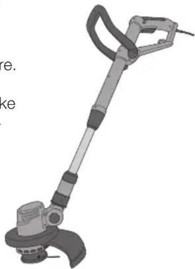
natural_image
Illustration of a metal detector device with no visible text or symbols on the device itselfnatural_image
Mechanical tool with curved handle and lever mechanism, shown in 3D rendering (no text or symbols)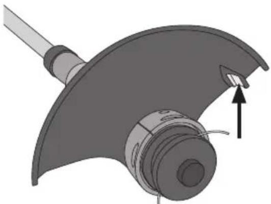
natural_image
Mechanical component diagram showing a curved housing with a lever and a directional arrow indicating motion (no text or symbols)Støttehjul
natural_image
Top-down view of a mechanical device with a circular housing and handle (no text or symbols visible)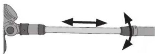
natural_image
Diagram of a mechanical lever with bidirectional arrows indicating motion (no text or symbols)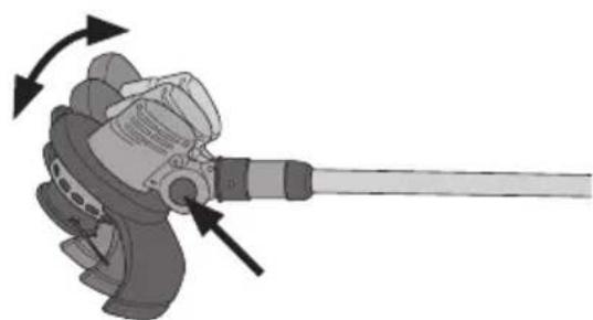
natural_image
Mechanical component diagram showing a lever mechanism with directional arrows indicating motion (no text or symbols)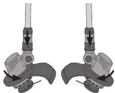
natural_image
Mechanical assembly diagram showing two identical configurations of a device with lever and base components (no text or symbols)natural_image
Hand inserting a component into a camera lens (no text or symbols visible)natural_image
3D rendering of a mechanical component with circular top and side holes, no text or symbols visiblenatural_image
Mechanical component diagram showing a spring assembly inside a housing (no text or symbols)natural_image
Mechanical assembly diagram showing a coiled spring mounted on a cylindrical housing (no text or symbols visible)natural_image
Mechanical component diagram showing a cylindrical housing with internal components and directional arrows indicating motion (no text or symbols)natural_image
Mechanical component diagram showing a rotating knob and housing (no text or symbols)-
Hvis det er unodig mye tråd ute kan den vikles opp ved at trådkassetten dreies moturs. Det ideelle er när endene stikker ca. 6 cm ut.
-
Sett lokket på plass og fest sneppertlåsene godt.
natural_image
Symbol of a trash bin crossed with no visible text or labelsSpesifikasjoner
Spenning 220–240 V AC, 50 Hz
Effekt 350 W
Turtall ubelastet 10000 o/min
Klippediameter 250 mm
Tråddiameter 1,5 mm
natural_image
Illustration of a mechanical power tool with a motor and lever (no text or symbols)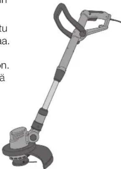
natural_image
Illustration of a metal detector device with no visible text or symbolsnatural_image
Mechanical tool with curved handle and lever mechanism, no visible text or symbolsSuoja
natural_image
Mechanical component diagram showing a curved blade and housing with an arrow indicating direction (no text or symbols)Välirengas
natural_image
Top-down view of a mechanical device with a circular component and handle (no text or symbols visible)Käyttö
Asetukset
natural_image
Diagram of a mechanical lever with bidirectional arrows indicating motion (no text or symbols)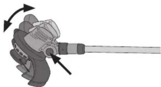
natural_image
Mechanical component diagram showing a lever mechanism with directional arrows indicating motion (no text or symbols)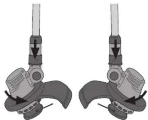
natural_image
Mechanical assembly diagram showing two identical configurations of a foot with adjustment arrows (no text or symbols)natural_image
Close-up of a hand pressing a button on a camera module (no text or symbols visible)natural_image
3D rendering of a mechanical component with a central circular base and two protruding wires (no text or symbols)natural_image
Mechanical component diagram showing a spring assembly inside a housing (no text or symbols)natural_image
Mechanical assembly diagram showing a coiled spring mounted on a cylindrical housing (no text or symbols visible)natural_image
Mechanical component diagram showing a cylindrical housing with internal components and directional arrows indicating motion (no text or symbols)natural_image
Mechanical component diagram showing a rotating knob and housing (no text or symbols)natural_image
Symbol of a trash bin crossed with no visible text or labelsTekniset tiedot
natural_image
Illustration of a mechanical power tool with a central blade and handle (no text or symbols)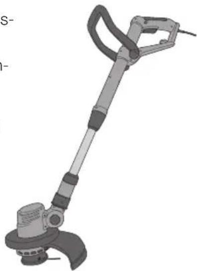
natural_image
Illustration of a metal detector device with adjustable handle and base (no text or symbols)natural_image
Mechanical tool with curved handle and lever mechanism, shown in 3D rendering (no text or symbols)Schutzvorrichtung
natural_image
Mechanical component diagram showing a curved mechanical assembly with a lever and directional arrow (no text or symbols)Stützrad
natural_image
Top-down view of a mechanical device with a circular housing and handle (no text or symbols visible)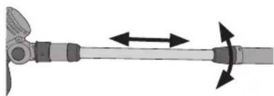
natural_image
Diagram of a mechanical lever with bidirectional arrows indicating motion (no text or symbols)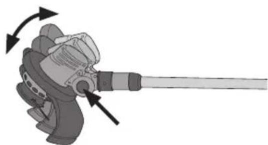
natural_image
Mechanical component diagram showing a lever with directional arrows indicating motion (no text or symbols)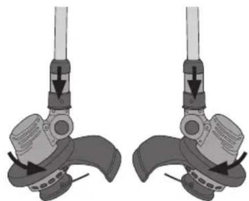
natural_image
Mechanical assembly diagram showing two identical configurations of a lever mechanism with arrows indicating motion direction (no text or symbols present)natural_image
Close-up of a hand pressing a button on a mechanical component (no text or symbols visible)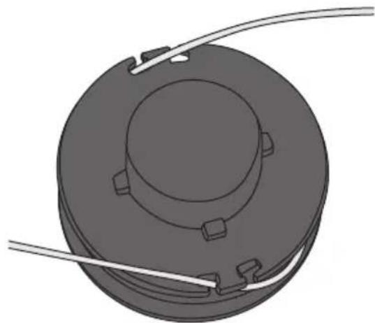
natural_image
3D rendering of a mechanical component with circular top and side holes, no text or symbols visiblenatural_image
Mechanical assembly diagram showing a spring-loaded component inside a housing (no text or symbols)natural_image
Mechanical assembly diagram showing a coiled spring mounted on a cylindrical housing (no text or symbols visible)natural_image
Mechanical component diagram showing a cylindrical housing with internal components and directional arrows indicating motion (no text or symbols)natural_image
Mechanical component diagram showing a rotating knob and housing (no text or symbols)natural_image
Symbol of a trash bin crossed out by two crossed lines, with no text or labels present.Technische Daten
Declaration of Conformity
Declares that this product complies with the requirements of the following directives and standards
Machinery directive 2006/42/EC
EN 60745-1:2009
EN ISO 10517:2009
EN 786/A2:2009
EMC directive 2004/108/EC
EN 55014-1:2006
EN55014-2/A1:2001
EN61000-6-3:2007
Low voltage directive 2006/95/EC
EN 60335-1:2002+A11
+A1+A12+A2+A13
EN 62233:2008
EN60335-2-29:2004
Klas Balkow
President
Insjön, Sweden, 2013-12-16
Sverige
Postal 10 - 13 Market Place
Kingston Upon Thames
Surrey
KT1 1JZ
Deutschland
Kundenservice Hotline: 040 2999 78111
E-Mail: kundenservice@clasohlson.de
Homepage
www.clasohlson.de

- Important!
- Viktig information:
- Contents
- Safety
- General Safety Requirements
- SAVE THESE INSTRUCTIONS.
- 1) Work area
- 2) Electrical safety
- 3) Personal safety
- 4) Use and maintenance of the power tool
- 5) Service
- Specific Safety Instructions for Grass Trimmers
- Grass trimmer symbol explanation
- Product description
- Assembly
- Front handle
- Safety guard
- Edging wheel
- Operating instructions Setup
- Connecting the extension lead
- Switching the trimmer on
- Care and maintenance
- Responsible disposal
- Specifications
- Grästrimmer 350 W
- Skydd
- Stödhjul
- Specifikationer
- Gresstrimmer, 350 W
- Støttehjul
- Spesifikasjoner
- Suoja
- Välirengas
- Käyttö
- Asetukset
- Tekniset tiedot
- Schutzvorrichtung
- Stützrad
- Technische Daten
- Declaration of Conformity
- Sverige
- Deutschland
Brand : Cocraft
Model : GT35
Category : Brush cutter