LS5T - Brush cutter Cocraft - Free user manual and instructions
Find the device manual for free LS5T Cocraft in PDF.


| Product Type | Brush Cutter |
| Brand | Cocraft |
| Model | LS5T |
| Engine Type | 2-Stroke Petrol |
| Engine Displacement | 42.7 cc |
| Power Output | 1.5 kW |
| Fuel Tank Capacity | 0.6 L |
| Cutting Width | 40 cm |
| Blade Type | 2-tooth metal blade |
| Shaft Type | Straight shaft |
| Overall Length | 180 cm |
| Weight | 6.5 kg |
| Noise Level (LWA) | 115 dB(A) |
| Vibration Level | 8.5 m/s² |
| Fuel Mixture Ratio | 50:1 (petrol:oil) |
| Starter Type | Recoil starter |
| Handle Type | J-handle |
| Safety Features | Throttle lock, blade guard |
| Maintenance | Clean air filter, sharpen blade, check spark plug |
| Spare Parts Availability | Air filter, spark plug, fuel cap, blade |
| User Manual | PDF downloadable |
Frequently Asked Questions - LS5T Cocraft
User questions about LS5T Cocraft
0 question about this device. Answer the ones you know or ask your own.
Ask a new question about this device
Download the instructions for your Brush cutter in PDF format for free! Find your manual LS5T - Cocraft and take your electronic device back in hand. On this page are published all the documents necessary for the use of your device. LS5T by Cocraft.
USER MANUAL LS5T Cocraft
Read the entire instruction manual carefully and make sure that you fully understand it before you use the equipment. Keep the manual for future reference.
Viktig information:
natural_image
Line drawing of a mechanical robotic device with articulated legs and wheels (no text or symbols)Art.no Model
41-2361
LS5000/520C-S
Ver. 20200324
Original instructions
Bruksanvisning i original
Originalbruksanvisning
Cocraft 5-Tonne Log Splitter
Art. no 41-2361 Model LS5000/520C-S
Please read the entire instruction manual before using the product and then save it for future reference. We reserve the right for any errors in text or images and any necessary changes made to technical data. In the event of technical problems or other queries, please contact our Customer Services (see address details on the back).
Warning:
When using this product, the safety instructions included in this manual should always be followed to avoid the risk of fire, electric shock, and personal injury.

Always unplug the mains lead from the wall socket before servicing or making any adjustments to the product.
Product safety symbols

Warning: Electric shock risk.

Warning: Risk of crushing. Keep hands well away from any moving parts during the entire splitting operation.
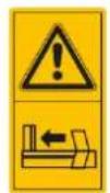
Warning: Risk of crushing. Always pay attention to the movement of the ram.
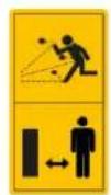
Warning: Objects ejected by the product can hit the operator or other persons in the vicinity and cause damage to property. Keep children and bystanders at a safe distance from the work area. Never allow another person to help you free a jammed log. If persons under 18 years of age are to operate the log splitter, they must be instructed in the safe use of the product and understand the hazards involved. Persons under 18 years of age must be supervised by an adult whilst operating the log splitter.

Bleed Screw

Make sure that you have read and understood the entire instruction manual before using the product.

Use protective eyewear and hearing protection.

Wear protective gloves.

Wear non-slip safety shoes.

Switch off and unplug the product whenever it is not in use and before it is cleaned or serviced.

Warning: None of the safety devices on the product must be modified in any way.

Warning: Always work alone with the log splitter. Two people must not operate the log splitter at the same time.

Warning: Never use the product in the rain or in wet conditions.
General safety instructions
-
Keep the working area tidy. Cluttered surfaces and benches invite accidents.
-
Do not use the machine in dangerous environments. The machine should not be used on moist or wet surfaces or in rain. Make sure that the work area is well lit. When working in dusty atmospheres, make sure that the air is adequately circulated. Do not operate power tools in explosive atmospheres, such as in the presence of flammable liquids, gases or dust.
-
Avoid electric shocks. Avoid body contact with earthed or grounded surfaces such as pipes, radiators, ranges and refrigerators when using power tools.
-
Keep children and bystanders away. Keep children and visitors at a safe distance from electrical machinery/tools and electric cables in the workplace.
-
Store power tools out of the reach of children. When not in use, power tools should be stored locked away in a safe place, away from children.
-
Do not force the machine. The correct feed rate makes the work better and safer.
-
Use the correct tool for the job. Do not force a tool to perform a task that it was not designed for.
-
Wear suitable attire. Do not wear any loose-fitting clothing, gloves, necklaces, bracelets or other jewellery that can get caught in moving parts. Non-slip footwear is recommended. Wear a hairnet or similar if you have long hair.
-
Always wear safety glasses. Normal glasses are not tough enough to withstand impacts. Use a dust mask or dust filter when working in dusty environments.
-
Connect dust extraction equipment. If the machine is equipped with dust extraction equipment, ensure that it is connected and used properly. Make sure to empty the dust bag regularly.
-
Do not abuse the mains lead. Do not carry the machine by its mains lead. Do not yank the mains lead to turn the power off, pull the plug out instead. Make sure that the mains lead does not come into contact with heat, oil, or sharp edges.
-
Secure the workpiece firmly. Where possible, use clamps or a vice. You can then operate the tool using two hands. This is much safer than holding the workpiece in one hand.
-
Do not overreach. Make sure that you stand steady and balanced all times.
-
Look after your tools. Keep blades sharp and clean for the best and safest performance. Follow the instruction manual's recommendations regarding lubrication and replacement of accessories. Inspect the mains lead regularly. If it is damaged it should be replaced by a qualified service technician. Inspect all leads and cables regularly to check for any damage. Make sure that the machine's handles and controls are clean, dry and free from oil and grease.
-
Turn the power off. Pull out the plug and push in the emergency stop button before servicing or changing any blades, drill bits, cutters or sanding discs.
-
Remove all spanners and repair tools. Make a habit of checking to make sure that the machine is free of all spanners and tools before turning the power on.
- Avoid accidental starts. Do not walk around with your finger on the trigger of a power tool if it is plugged in. Make sure that the on/off switch is set to OFF before plugging in any power tool.
- Use the correct extension leads. If you use extension leads outdoors, only use those designed for outdoor use. Only use extension leads with thick enough diameter core wires and roll out the whole lead.
- Use common sense and be careful. Think carefully before carrying out every action, so that it is carried out safely. Never operate machines/power tools when you are tired or under the influence of medicine.
- Inspect the tool for damage. Before starting the tool, make sure that the guards and other parts are undamaged and working properly, that moving parts can rotate freely and are correctly aligned, that no moving parts can get caught and that there is no fault or defect that could affect the performance of the machine. A safety guard or any other part that is damaged should be repaired by a tradesman or replaced. Damaged power leads and switches must always be replaced by a tradesman. Never operate a tool if you cannot stop or start the tool comfortably.
- Use only recommended accessories. The use of non-recommended accessories can cause accidents and personal injury.
- Repairs should only be carried out by a qualified repair person using genuine identical replacement parts.
- All power tools should be connected to the mains via a portable residual current device (PRCD). The product must not be modified or used for any other purpose than that for which it has been designed. Regularly check that all screws and nuts are securely tightened.
Specific safety instructions for log splitters
- The log splitter is only intended to be used by one operator at a time. The log splitter must not be operated by more than one person at a time.
- Locate the log splitter on dry, level ground which is not slippery.
- Make sure that branches are cut off flush with the log before splitting.
- Save the instruction manual, make sure that it accompanies the log splitter if it is borrowed.
- Split wood in the direction of the grain. Do not attempt to split wood across the grain.
- Read the warning labels on the log splitter and make sure that they are legible.
- Make sure that the electrical socket you intend to use has the correct voltage (230 V) before connecting the log splitter.
- Never attempt to adjust the force setting yourself. The log splitter is pre-set at the factory for a maximum splitting force of 6 tonnes.
- Tampering with the pressure settings can lead to diminished performance and damage to the machine and result in serious person injury.
- Do not attempt to split two logs at the same time.
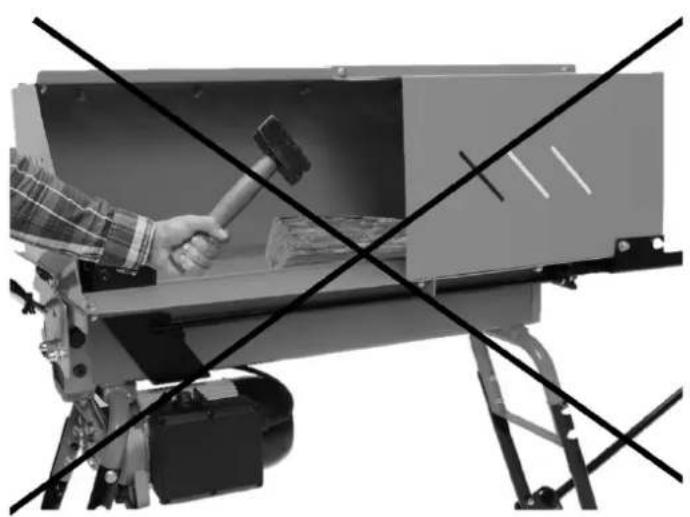
- Never attempt to right a leaning log with your hand whilst the ram is in motion. Stop the machine and move the log so that it is standing vertically.
- Never attempt to hold a log with your hand whilst the ram is in motion.
- If a log jams or fails to be split because it exceeds the capacity of the ram, release both control levers and let the ram return to its original position, otherwise there is a risk that the motor will become damaged by overheating.
- Switch off the log splitter and disconnect it from the mains supply whenever you take a break and before starting any maintenance procedures. Make sure that log splitter cannot be started by any children or unauthorised person.
- Make sure that all the safety features on the log splitter are correctly fitted and functioning properly.
- Wear safety glasses, ear defenders and safety shoes if necessary.
- Always stand in such a way that you can perform all work tasks whilst maintaining good balance and grip the control levers in both hands.
- Keep your hands and fingers well away from the and splitting wedge. When operating machines, always use your common sense and be careful.
- Make sure that there are no bystanders or pets close to the machine, sharp splinters can be ejected by the blade with great force.
- Connect the log splitter to a wall socket via an RCD.
-
Never use the log splitter in the rain or wet conditions.
-
Never use the log splitter if the power switch, plug, mains lead or any other part is damaged. The defective part must be replaced by a qualified repair person.
• Make sure that this instruction manual always accompanies the product and that it is kept accessible and legible. - Make sure that everyone who uses the product has read and understood the entire instruction manual.
- Always be alert and careful when operating the product. Think carefully before carrying out every action, so that it is carried out safely. Never use the product when you are tired, sick or under the influence of alcohol, drugs or medicine.

Other safety symbols
Warning: Do not overreach. Keep proper footing and balance at all times. Never stack your logs in such a way that you need to stretch to reach them. Only use your hands to operate the log splitter. Never use other parts of the body or devices which could enable your hands to become crushed between the splitting wedge and the log. Pay attention to the movement of the hydraulic ram at all times. Never stack logs on top of each other and try to split two at once. Never attempt to load a log into the log splitter while the ram is in motion. Keep hands away from moving parts.

Warning: Keep your hands clear of the ram when it is returning after it has split the log. The log splitter is designed to stop only when the ram has returned to its original position. Keep your hands away from any splits and cracks which open in logs. They may close suddenly which could cause serious personal injury. Never attempt to remove jammed logs by hand.

Consider the environment, dispose of waste oil in accordance with local regulations.

Make sure that the log splitter is undamaged, that none of the safety features are missing and that they are fitted correctly and working. Never operate the log splitter if any of the safety features is damaged or missing. Check the oil level before starting the log splitter.
Product description
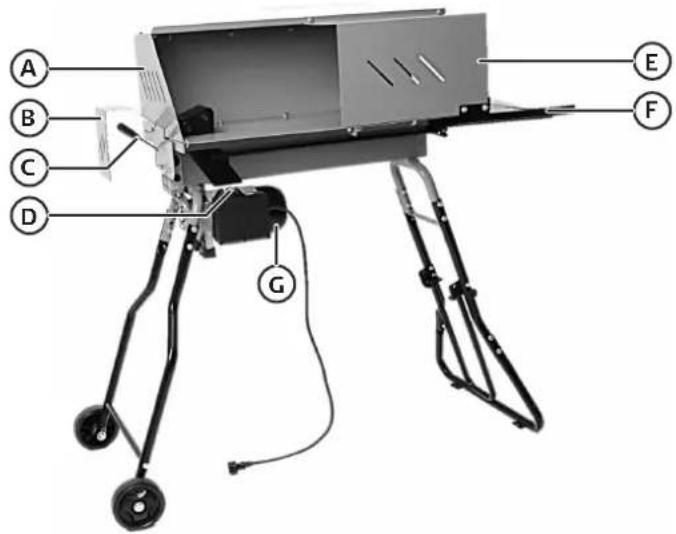
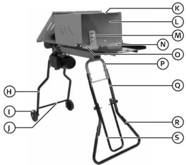
A End guard
B Control lever guard
C Control lever
D Power switch
E Front guard
F Log collector table
G Electric motor
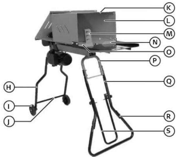
H Wheeled left support legs x 2
I Wheels x 2
J Cross member
K Upper guard
L Rear guard
M Splitting wedge
N Rear log retaining plate
O Front log retaining plate
P Log splitter leg
Q Right support leg upper sections x 2
R Right support leg lower sections x 2
S Handle

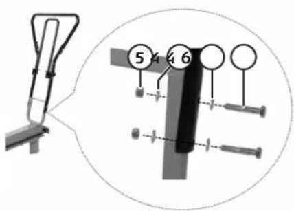
Bolt M6 x 14 2 pcs

Washer M6 2 pcs

Nut M6 2 pcs

Washer M8 90 pcs

Lock nut M8 44 pcs

Bolt M8 x 45 14 pcs
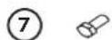
Bolt M8 x 16 28 pcs

Coach bolt M8 x 45 4 pcs
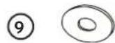
Washer 14 6 pcs

Coach bolt M8 x 40 2 pcs

Locking knob 2 pcs
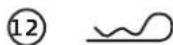
R-clip
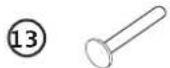
Axel 2 pcs
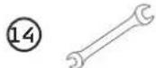
Spanner 2 pcs

Spare gasket for oil dipstick 1pcs
Assembly

Important
Always get someone to help you assemble the log splitter. The log splitter is heavy and it will be easier and safer if two people carry out the assembly.
When splitting logs however, you must always operate the controls of the machine by yourself. Two people must never operate the machine at the same time.
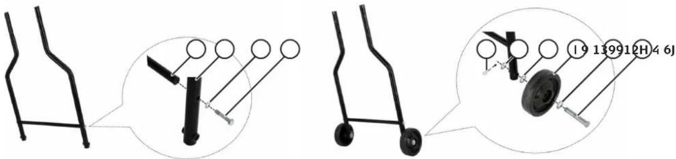
- Wheeled left support legs
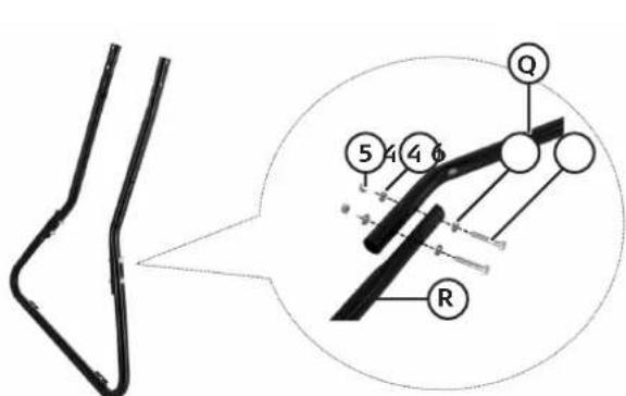
- Right support legs
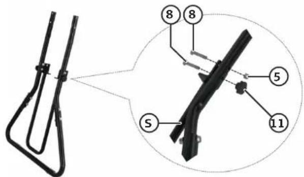
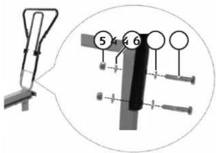
- Handle
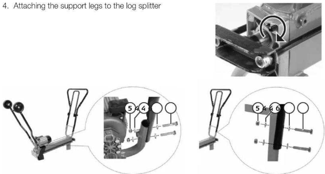
Turn the log splitter upside down and bolt the legs onto it.
natural_image
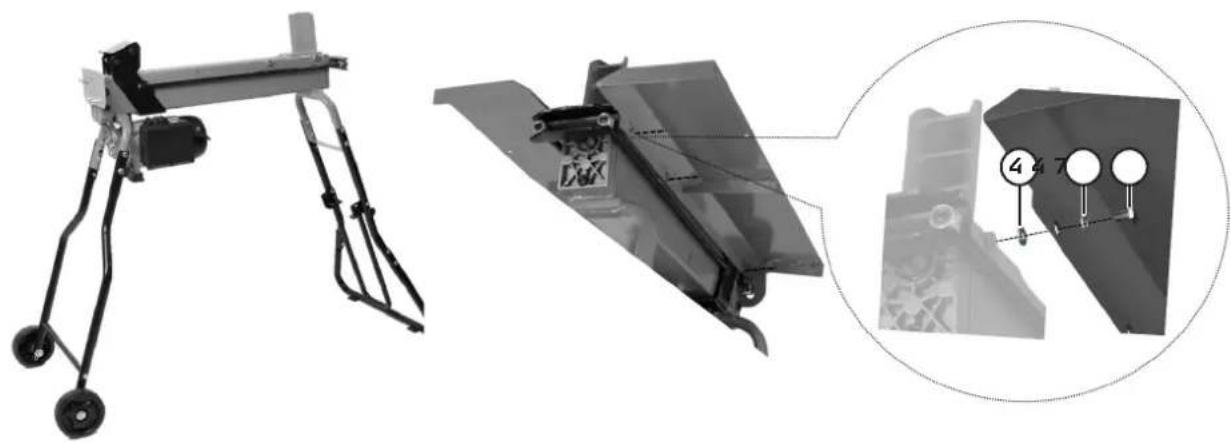
Technical illustration of a mechanical assembly with labeled parts, showing front and side views (no text or symbols present)- Turn the log splitter over so that it is standing on its legs. Attach the two log retaining plates, front and rear.
natural_image
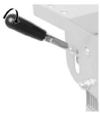
Close-up of a mechanical lever handle with a black-handled lever and mounting bracket (no text or symbols visible)- Control lever
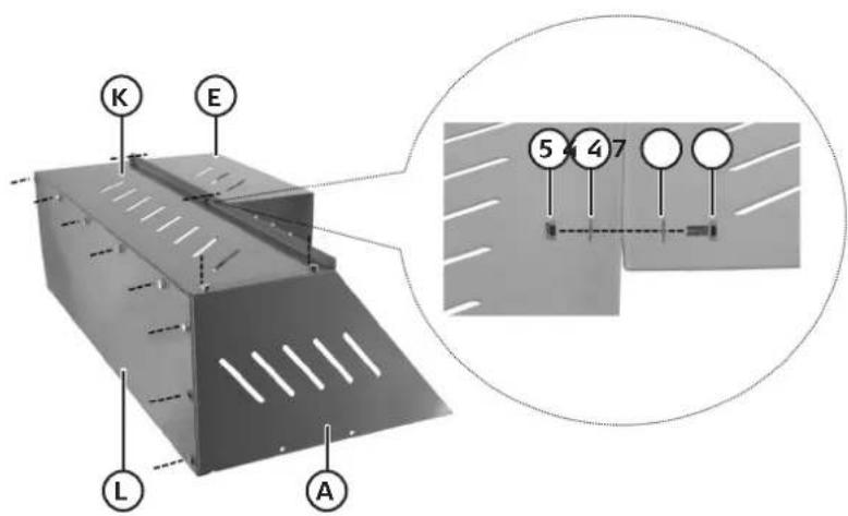
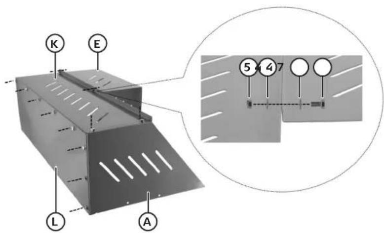
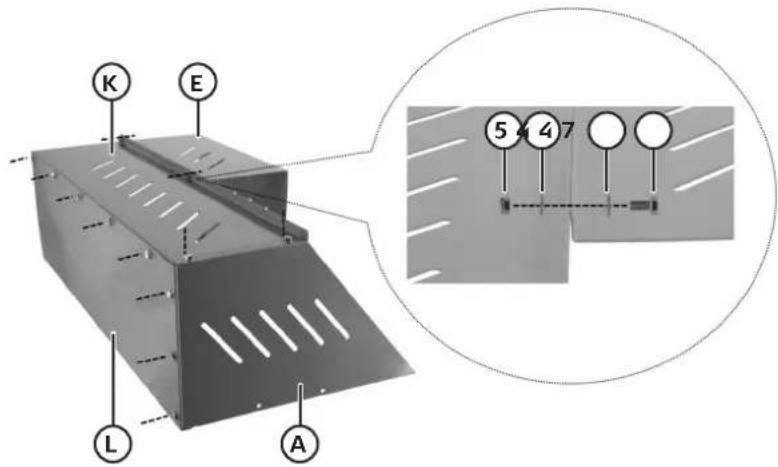
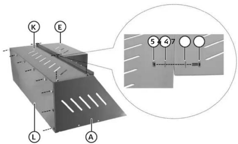
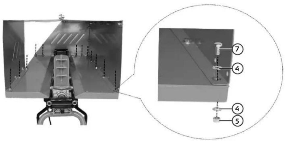
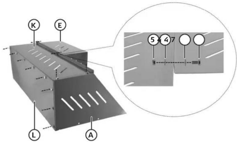
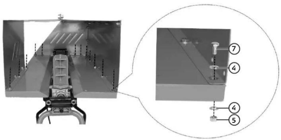
- Assembling the log splitter guard
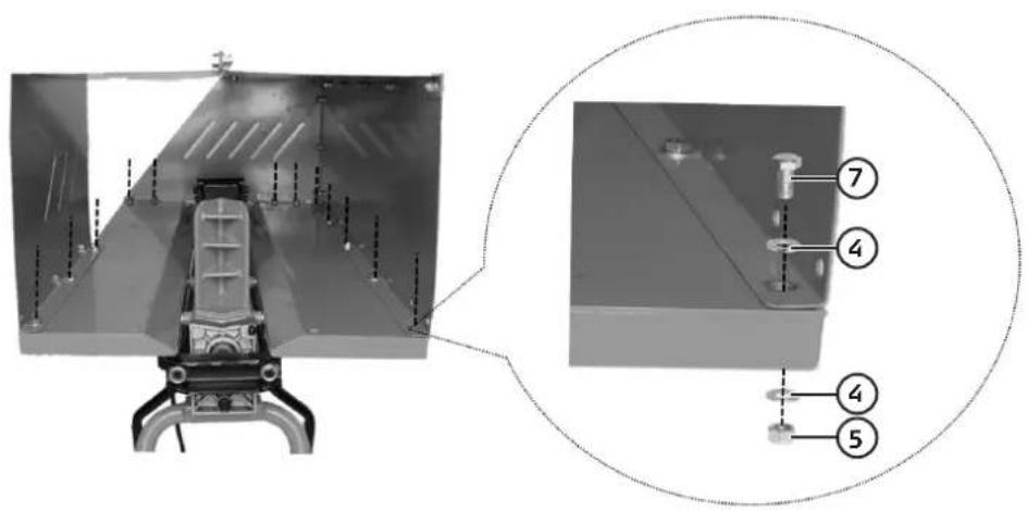
- Attaching the guard to the log splitter
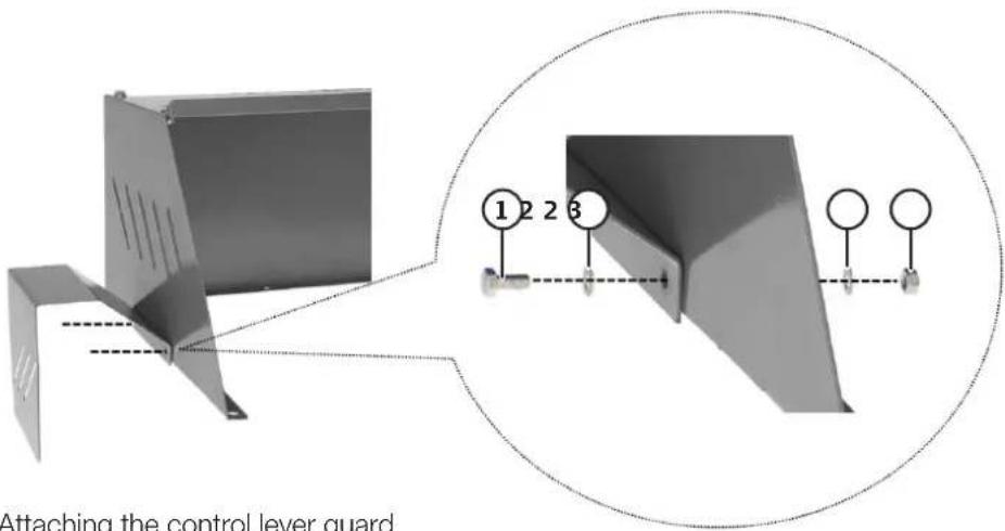
- Attaching the control lever guard
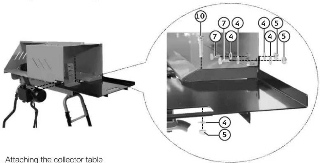
- Attaching the collector table
Instructions for use
Handle
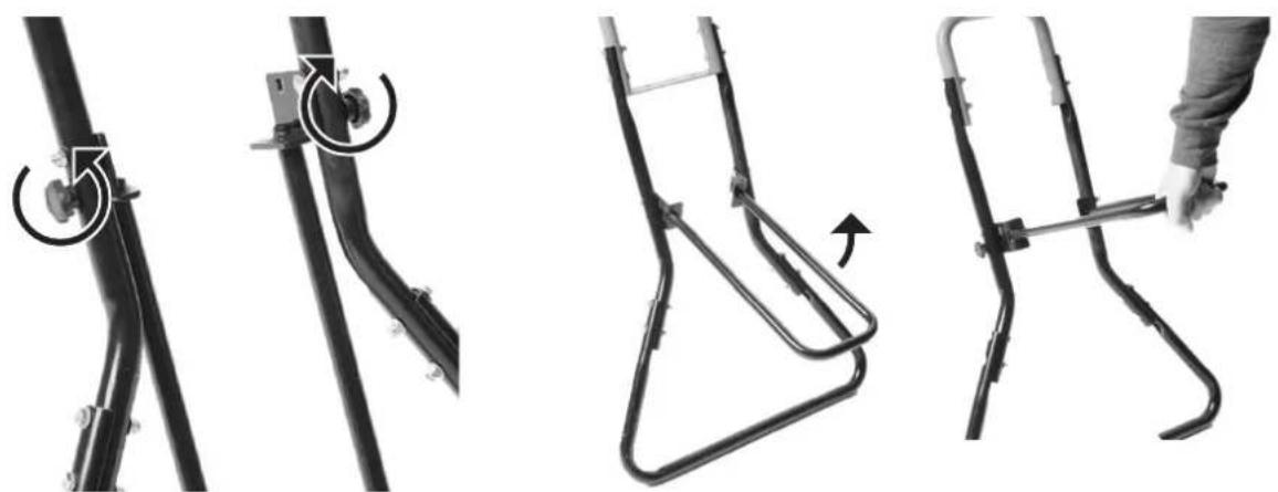
- The handle can be raised to make it easier to move the log splitter.
natural_image
Four-panel black-and-white diagram showing mechanical components with rotational arrows, no text or symbols present.- Undo the two locking knobs and remove the coach bolts.
- Lift the handle up until the holes in the end line up with the lower holes in the legs, refit the coach bolts and tighten the locking knobs.
Before starting
- The log splitter should be placed on a firm and level surface.
- Inspect the log splitter to make sure that all nuts and bolts are securely tightened and that there is no visible damage to the mains lead, the plug or the power switch.
- Connect the mains lead to an earthed wall socket. The wall socket should be protected by a residual current device (RCD) with an actuating current of 30 mA. Do not route the mains lead where it could be damaged or where someone could trip over it.
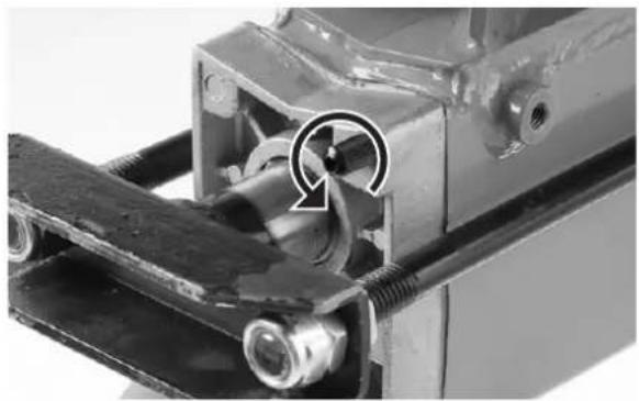
△ Important: Unscrew the bleed screw 3 or 4 turns to ensure a detectable flow of air to the oil tank while the log splitter is in operation.
natural_image
Close-up of a mechanical assembly with a circular arrow indicating rotation or adjustment (no visible text or symbols)Splitting a log
- Always place the least knotty end of the log toward the wedge, always split along the grain.
- Lay the log as stably as possible between the log retaining plates.
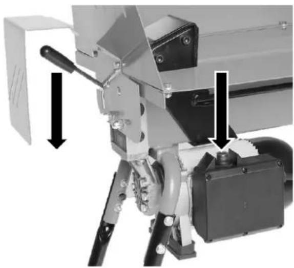
- Start the motor by pressing and holding in the power switch.
- Start the hydraulic ram by depressing the control lever.
- The hydraulic ram will now force the log against the splitting wedge.
- Release the control lever and the power switch to discontinue the splitting operation, the return springs will now return the ram to its starting position.
natural_image
Mechanical device with lever and base components, showing mechanical assembly (no visible text or symbols)△ Important: If the wood does not start to split after 5 seconds despite full pressure: release the control lever and the power switch and let the ram return to the starting position. Turn the log through 90 degrees and try to split it again.
If the log jams
- Stop the log splitting operation.
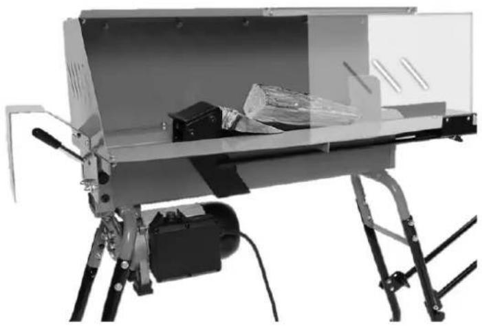
- When the ram has returned to the starting position: place a wooden wedge under the jammed log.
- Start the log splitter and force the wedge under the log using the ram.
- Repeat the procedure with a larger wedge if necessary.
natural_image
Exterior view of a mechanical device with visible components and mounting base (no text or symbols)△ Important: Never try to dislodge a log which is under tension, it could split and fly off with great force and damage the log splitter or cause an injury.
natural_image
Black-and-white photo of a hand hammering a mechanical device with crossed lines indicating resistance or crossed-out (no text or symbols)Care, maintenance and storage
• Always unplug the mains lead from the wall socket before any servicing or cleaning.
- Clean all the parts of the log splitter with a brush and dry rags.
- Always unplug the log splitter and store it in a dry, clean and non-corrosive environment out of children's reach whenever it is not in use. Make sure that the storage temperature does not fall below -25^ .
- Make sure that the bleed screw is closed before the log splitter is moved or put away, otherwise oil could leak out. If the bleed screw is left open when the log splitter is stored away, the oil will absorb moisture from the air which can lead to corrosion within the hydraulic system.
- The splitting wedge should be kept sharp by filing it regularly with a fine-toothed file.
Checking the oil level/changing the oil
△ Important: Always get someone to help you change/check the oil. It will be easier and safer if two people are involved and can assist each other.
The first oil change should take place after 50 hours of operation and thereafter after every 250 hours of operation.
Checking the oil level
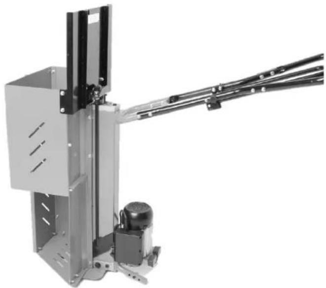
natural_image
Industrial robotic arm with articulated joints and control panel (no visible text or symbols)- Remove the wheeled left support legs and stand the log splitter on its end as shown in the picture.
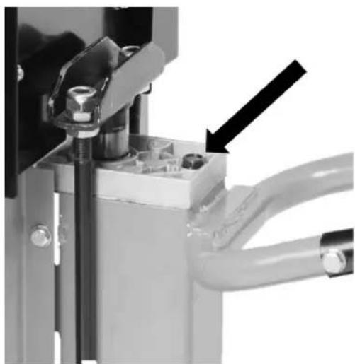
natural_image
Close-up of a mechanical assembly with a black arrow pointing to a component (no visible text or symbols)- Make sure that the area around the oil dipstick is clean and free from dust and debris.
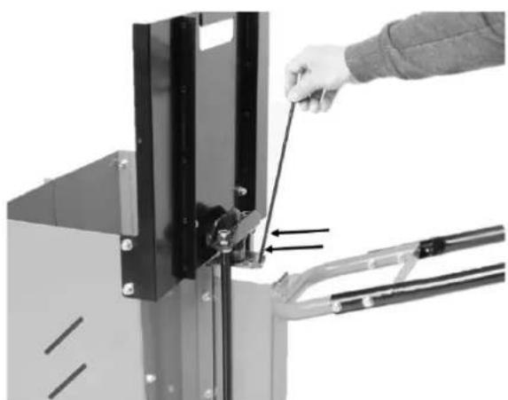
natural_image
Close-up of a hand using a tool to adjust or install a metal bracket component (no text or symbols visible)-
Unscrew the dipstick and wipe it clean. Insert the dipstick into the oil cylinder but do not screw it on. Remove the dipstick and check the oil level. The oil level should be between the two grooves on the dipstick.
-
Screw the dipstick back in again. Do not overtighten the dipstick, doing so could damage the seal.
Changing the oil
- Follow steps 1 and 2 in the Checking the oil level section above.
- Suction out the oil using an oil suction pump. Take the used oil to your local household recycling site for safe disposal.
- Replace the old oil with new oil (3.2 litres of hydraulic oil).
- Check the oil level and screw the dipstick back on again. Do not overtighten the dipstick, doing so could damage the seal.
Troubleshooting guide
| The log doesn’t split. • Log improperly positioned. Turn the log around or rotate it.• The log is too big or too hard.• The wedge is blunt or damaged. Sharpen the wedge (refer to the Care, maintenance and storage section).• Oil pressure low, check the oil level (refer to the Care, maintenance and storage section). |
| The hydraulic ram moves jerkily, makes strange noises and vibrates heavily. |
| The motor does not start. • Is the plug securely connected to the wall socket?• Is the wall socket energised? |
Responsible disposal
This symbol indicates that the product should not be disposed of with general household waste. This applies throughout the entire EU. In order to prevent any harm to the environment or health hazards caused by incorrect waste disposal, the product must be handed in for recycling so that the material can be disposed of in a responsible manner. When recycling your product, take it to your local collection facility or contact the place of purchase. They will ensure that the product is disposed of in an environmentally sound manner.
Specifications
Rated voltage 230 V AC, 50 Hz
Power 1500 W S3 80%
IP rating IP54
Log capacity ∅ 50–250 mm, length 150–520 mm
Rec. operating temp +5 °C to +40 °C
Splitting force 5 t
Hydraulic oil 3.2 L
Size 1560 x 590 x 1330 mm
Weight 71 kg
Vedklyv 5T
Art.nr 41-2361 Modell LS5000/520C-S
① Built M6 x 14 2 st
② Bricka M6 2 st
③ Mutter M6 2 st
④ Bricka M8 90 st
⑨ Bricka 14 mm 6 st
10 Vagnsbult M8 x 40 2 st
11 Låsvred
⑫ Låssprint 2 st
⑬ Hjulaxel 2 st
⑭ Blocknycklar 2 st
natural_image
Close-up of a mechanical component with a circular arrow indicating rotation or adjustment (no visible text or symbols)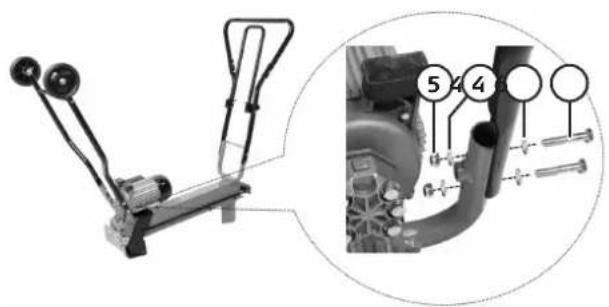
natural_image
Technical illustration of a mechanical assembly with labeled parts, showing front and side views (no text or symbols present)natural_image
Close-up of a mechanical lever handle with a black-handled lever and metal bracket (no text or symbols visible)- Montera klyvreglaget
natural_image
Four-panel black-and-white diagram showing mechanical components with arrows indicating motion or assembly (no text or symbols)natural_image
Close-up of a mechanical assembly with a circular arrow indicating rotation (no visible text or symbols)Klyvning
natural_image
Mechanical device with lever and base components, showing mechanical assembly (no visible text or symbols)natural_image
Exterior view of a mechanical device with tripod base and internal components (no visible text or symbols)natural_image
Black-and-white photo of a hand hammering a mechanical device with crossed lines indicating resistance or crossed-out (no text or symbols)natural_image
Industrial robotic arm with articulated joints and a motor, no visible text or symbolsnatural_image
Close-up of a mechanical assembly with a black arrow pointing to a component (no visible text or symbols)natural_image
Close-up of a hand using a tool to adjust or install a metal bracket component (no text or symbols visible)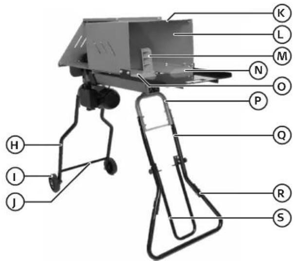
⑨ Skive 14 6 stk.
⑩ Vognbolt M8 x 40 2 stk.
11 Låseratt
12 Låsesplint 2 stk.
⑬ Hjulaksel 2 stk.
14 Nøkler 2 stk.
⑮ Reservepakning for oljepeilestokk 1 stk.
Montering

Viktig!
- Fremre støtteben
- Håndtak
- Monter bena på vedkløyveren.
natural_image
Close-up of a mechanical component with a circular arrow indicating rotation or adjustment (no visible text or symbols)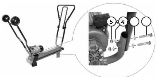
natural_image
Mechanical lever assembly diagram showing a lever mechanism and a close-up of a mechanical component with labeled parts (no text or symbols present)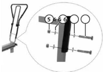
natural_image
Technical illustration of a mechanical assembly with labeled parts, showing front and side views (no text or symbols present)1. Kløyvebord
natural_image
Close-up of a mechanical lever handle with a black-handled lever and metallic shaft (no text or symbols visible)- Kløyvespak
- Beskyttelsesdeksel
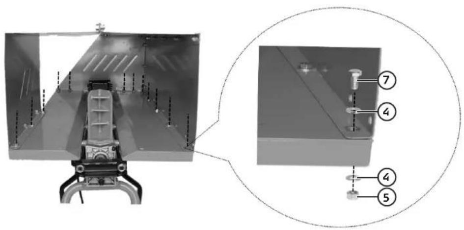
- Monter beskyttelsesdekselet på vedkløyveren.
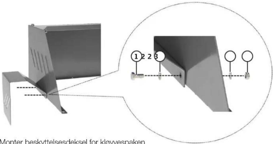
- Monter beskyttelsesdeksel for kløyvespaken
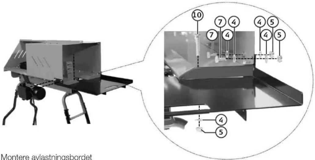
- Montere avlastningsbordet
Bruk
Håndtak
natural_image
Four-panel black-and-white diagram showing mechanical components with rotational arrows, no text or symbols present.natural_image
Close-up of a mechanical assembly with a circular arrow indicating rotation or motion (no visible text or symbols)Kløyving
natural_image
Mechanical assembly with mechanical components and directional arrows indicating motion (no text or symbols)natural_image
Exterior view of a mechanical device with mounted components and a ladder (no visible text or symbols)natural_image
Black-and-white photo of a hand hammering a mechanical device with crossed lines indicating resistance or crossed-out (no text or symbols)natural_image
Mechanical assembly with metallic frame and articulated arm, no visible text or symbolsnatural_image
Close-up of a mechanical assembly with a black arrow pointing to a component (no visible text or symbols)natural_image
Close-up of a hand using a tool to adjust or install a metal bracket component (no text or symbols visible)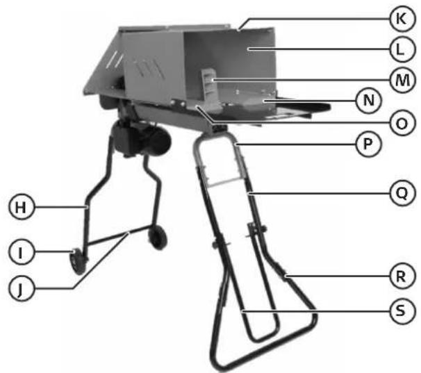
natural_image
Close-up of a mechanical component with a circular arrow indicating rotation or adjustment (no visible text or symbols)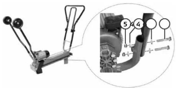
natural_image
Technical illustration of a mechanical assembly with labeled parts, showing front and side views (no text or symbols)natural_image
Close-up of a mechanical lever handle with a black-handled lever and metal bracket (no text or symbols visible)- Halkaisusäädin
- Suojapelti
natural_image
Four-panel black-and-white diagram showing bicycle support mechanisms: bracket, lock switch, ramp, and ladder (no text or symbols)natural_image
Close-up of a mechanical assembly with a circular arrow indicating rotation or motion (no visible text or symbols)Halkaisu
natural_image
Mechanical device with lever and base components, showing mechanical assembly (no visible text or symbols)natural_image
Exterior view of a mechanical device with a mounted sensor and control panel (no visible text or symbols)natural_image
Black-and-white photo of a hand hammering a device with a gavel, crossed by two diagonal lines (no text or symbols visible)Huolto ja säilytys
natural_image
Industrial robotic arm with articulated joints and control panel (no visible text or symbols)natural_image
Close-up of a mechanical assembly with a black arrow pointing to a component (no visible text or symbols)natural_image
Close-up of a hand using a tool to adjust or install a metal bracket component (no text or symbols visible)①

Bolzen M6 x 14 2 St.
2

natural_image
Close-up of a mechanical component with a circular arrow indicating rotation or adjustment (no visible text or symbols)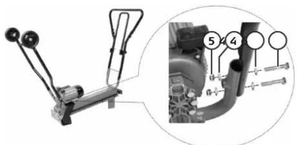
natural_image
Mechanical lever assembly diagram with numbered parts, no visible text or symbols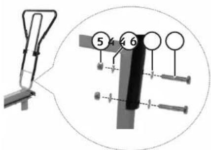
natural_image
Technical illustration of a mechanical device with labeled parts, showing front and side views (no text or symbols present)1. Spaltisch
natural_image
Close-up of a mechanical lever handle with a black-handled lever and metal bracket (no text or symbols visible)- Spalthebel
- Schutzblech
natural_image
Four-panel black-and-white diagram showing mechanical components with rotational arrows, no text or symbols present.natural_image
Close-up of a mechanical component with a circular arrow indicating rotation or adjustment (no visible text or symbols)Spalten
natural_image
Mechanical device with lever and base components, showing mechanical assembly (no visible text or symbols)natural_image
Exterior view of a mechanical device with mounted components and legs (no visible text or symbols)natural_image
Black-and-white photo of a hand hammering a mechanical device with crossed lines indicating prohibition (no text or symbols visible)natural_image
Industrial robotic arm with articulated joints and control panel (no visible text or symbols)natural_image
Close-up of a mechanical assembly with a black arrow pointing to a component (no visible text or symbols)natural_image
Close-up of a hand using a tool to adjust or install a metal bracket component (no text or symbols visible)Declaration of Conformity
Declares that this product complies with the requirements of the following directives and standards
Product Quality & Compliance Mgr
Insjön, Sweden, 2020-03-24
CLAS OHLSON AB, SE-793 85 INSJÖN, SWEDEN
Sverige
| Kundtjänst | tel: 0247/445 00e-post: kundservice@clasohlson.se |
| Internet | www.clasohlson.se |
| Post | Clas Ohlson AB, 793 85 INSJÖN |
Norge
| Kundesenter | tlf.: 23 21 40 00e-post: kundesenter@clasohlson.no |
| Internett | www.clasohlson.no |
| Post | Clas Ohlson AS, Postboks 485 Sentrum,0105 OSLO |
Suomi
| Customer Service | contact number: 020 8247 9300e-mail: customerservice@clasohlson.co.uk |
| Internet | www.clasohlson.co.uk |
| Postal | Clas Ohlson Ltd, Aquilla House (First floor),1 Becketts Wharf, Lower Teddington Road,Hampton Wick, Kingston Upon Thames, KT1 4ER |
Deutschland
| Kundenservice | Hotline: 040 2999 78111E-Mail: kundenservice@clasohlson.de |
| Homepage | www.clasohlson.de |
| Postanschrift | Clas Ohlson GmbH, Valentinskamp 88 |
20355 Hamburg


- Viktig information:
- Cocraft 5-Tonne Log Splitter
- Warning:
- Product safety symbols
- General safety instructions
- Specific safety instructions for log splitters
- Other safety symbols
- Product description
- Assembly
- Important
- Instructions for use
- Handle
- Before starting
- Splitting a log
- If the log jams
- Care, maintenance and storage
- Checking the oil level/changing the oil
- Checking the oil level
- Changing the oil
- Responsible disposal
- Specifications
- Vedklyv 5T
- Klyvning
- Montering
- Kløyvebord
- Bruk
- Håndtak
- Kløyving
- Halkaisu
- Huolto ja säilytys
- Spaltisch
- Spalten
- Declaration of Conformity
Brand : Cocraft
Model : LS5T
Category : Brush cutter