
LD 174202 - Uncategorized ECG - Free user manual and instructions
Find the device manual for free LD 174202 ECG in PDF.


| Product Type | Uncategorized Electronic Device |
| Brand | ECG |
| Model | LD 174202 |
| Dimensions (Approx.) | 200 x 150 x 50 mm |
| Weight | 0.5 kg |
| Power Supply | 5V DC, 1A via USB cable (cable included) |
| Power Consumption | 5W max |
| Main Functions | On/Off operation, adjustable settings, status indicator |
| Control Type | Push buttons |
| Display Type | LED indicator |
| Material | ABS plastic |
| Color | Black/White (depending on variant) |
| Operating Temperature | 0°C to 40°C |
| Storage Temperature | -10°C to 60°C |
| Humidity | 20% to 80% (non-condensing) |
| Cleaning and Maintenance | Wipe with a soft, dry cloth. Do not use liquids or solvents. |
| Safety Precautions | Keep away from water and moisture. Do not disassemble. Use only provided power adapter. |
| Spare Parts Availability | Contact manufacturer for spare parts; not sold separately. |
| Repair Service | Authorized service center only. See warranty card. |
| Warranty | 2 years limited warranty |
| Certifications | CE, RoHS |
Frequently Asked Questions - LD 174202 ECG
User questions about LD 174202 ECG
0 question about this device. Answer the ones you know or ask your own.
Ask a new question about this device
Download the instructions for your Uncategorized in PDF format for free! Find your manual LD 174202 - ECG and take your electronic device back in hand. On this page are published all the documents necessary for the use of your device. LD 174202 by ECG.
USER MANUAL LD 174202 ECG
SWIVEL AND TILTING LED TV WALL MOUNT INSTRUCTION MANUAL
Read carefully and save for future use!
Please refer to a qualified professional to install the wall mount properly. Prior to the wall mount installation, check the contents of the assembly set and inform your vendor in case you discover any components are missing or are defective. Do not use defective components!! Use the wall mount solely for the purpose intended by the manufacturer. Make sure the wall is capable of supporting (especially in terms of weight) the wall mount prior to installing. Also make sure no power, water, gas or other lines are located behind the wall in the installation area. Keep the specified distance between the TV and wall (depends on the TV model). Install the wall mount to a safe location, which does not present a risk to anyone. Once the wall mount and flat screen TV are mounted, ensure that the stability and safety are sufficient. This inspection shall be repeated on a regular basis, every 2 months.
The equipment is intended to be installed on wooden crossbars or solid concrete walls. Prior to the installation, make sure the assembly surface has he necessary loading capacity to carry the total weight of the TV and mount. Never exceed the maximum capacity of the holder 25 kg including cables.
This product is designed for household use only. Using the product outdoors can result in product failure or injury.
The manufacturer is not liable for damages to the equipment and health caused by improper installation of the wall mount.
- Read all instructions and make sure you understand them prior to the installation. If you are not sure about any part of the installation process, contact a professional technician for support.
- The wall or surface on which the mount will be anchored to shall be capable of carrying the entire weight of the wall mount and TV. Reinforcement will be required otherwise.
-
The installation requires the cooperation of at least two people and the use of a mechanical security mechanism and suitable tools. Otherwise it could result in damage to property or serious injury or fatal injury.
-
Follow all instructions and recommendations concerning adequate ventilation and selecting a suitable location for anchoring the TV. See the your TV user's manual for more information.
- The product contains smaller pieces, which upon being inhaled or swallowed can lead to choking. Keep these pieces away from children!
DESCRIPTION
Assembly set

A1 A2 A3 A4 A5 A6


B1 B2 B3


C1
| Identification Unit(s) Description | |
| A1 4 Bolt M4 × 20 mm | |
| A2 4 Bolt M5 × 20 mm | |
| A3 4 Bolt M6 × 20 mm | |
| A4 4 Bolt M8 × 20 mm | |
| A5 4 Spacer | |
| A6 4 Washer for bolts | |
| B1 3 Long bolt | |
| B2 3 Dowel | |
| B3 3 Washer for long bolt | |
| C1 1 Magnetic level |
ASSEMBLY
1A – Concrete wall assembly
Apply the wall board to the wall, align into a level position and use it as a template to mark three holes. Drill three holes 10 mm in diameter and 70 mm deep. Insert three dowels (B2) into the holes and fixate the wall board to the wall using long screws (B1) and washers (B3). Tighten the bolts firmly, but not too much.
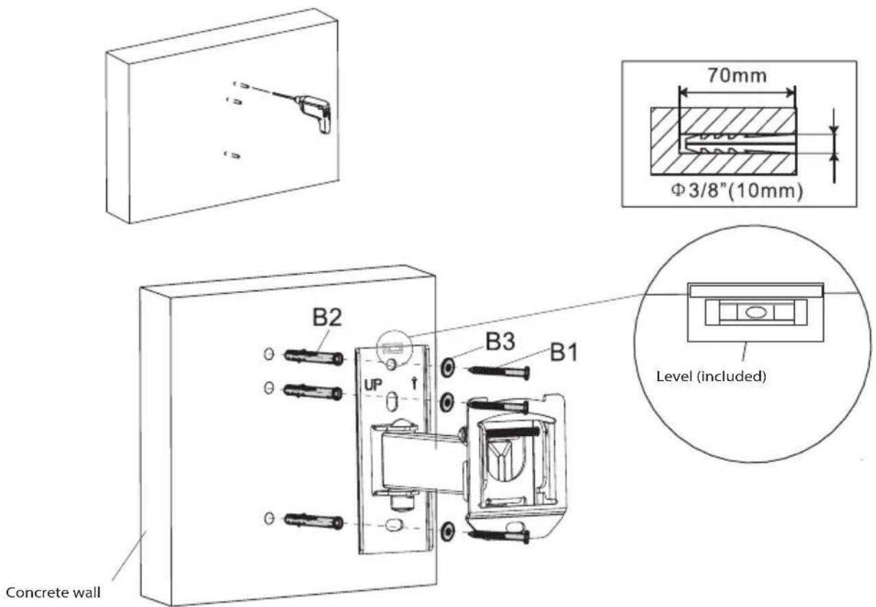
1B – Wooden crossbar assembly
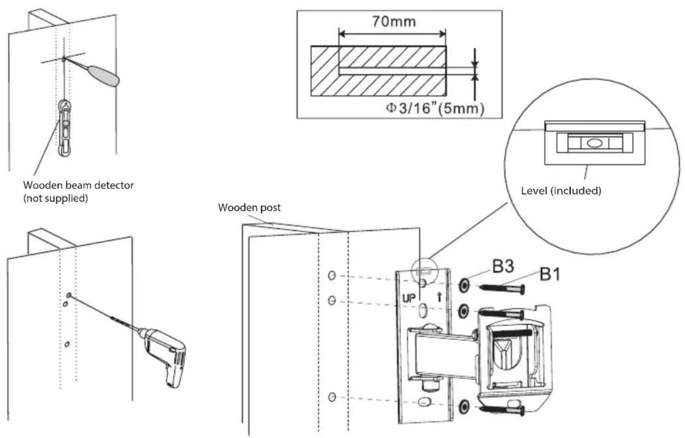
Use the wall board as a template. Make sure that it is level, mark three mounting holes into the wooden post. Drill three holes 5 mm in diameter and 70 mm deep. Apply the wall board horizontally and fixate to the wall using three long bolts (B1) and washers (B3). Tighten the bolts firmly, but not too much.
2A - Mounting the TV adapter panel to the TV with flat back
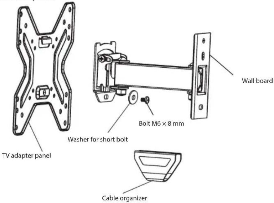
Check to see how the mounting holes are arranged on the back side of your television set. Select the proper bolts for your TV. Remove the TV adapter plate from the wall plate and attach it to the TV with the four screws (A1–A4), spacer (A5) and washer (A6). Tighten the bolts firmly, but not too much.
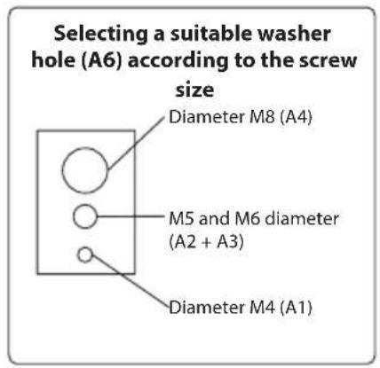
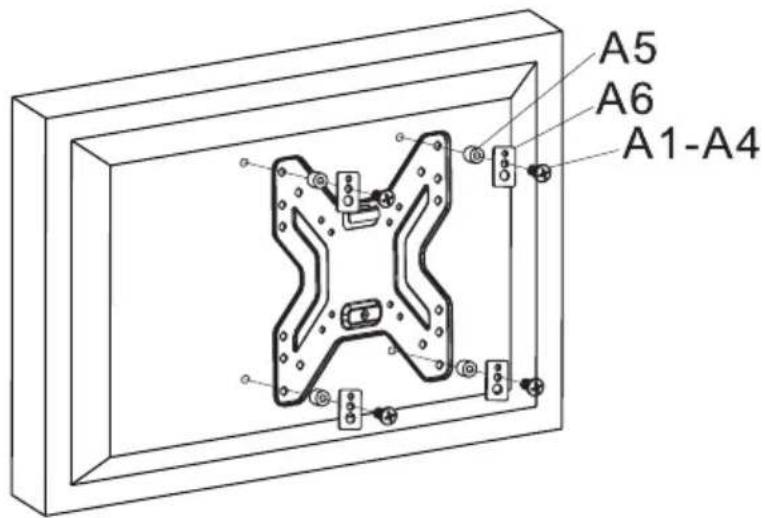
Warning: If the holes on the back of your TV are too shallow and none of the included screws fit into them, use the appropriate screws of your choice.
2B - Mounting the TV adapter panel to the TV with rounded back
Check to see how the mounting holes are arranged on the back side of your television set. Select the proper bolts for your TV. Remove the TV adapter plate from the wall plate and attach it to the TV with the four screws (A1–A4), spacer (A5) and washer (A6). Tighten the bolts firmly, but not too much.
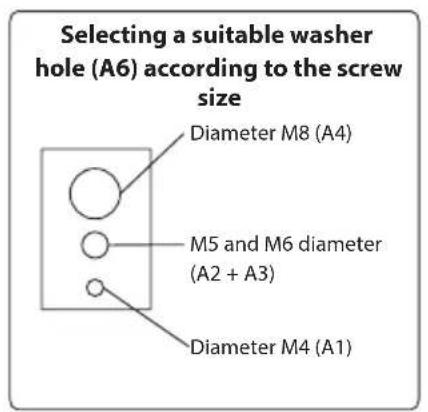
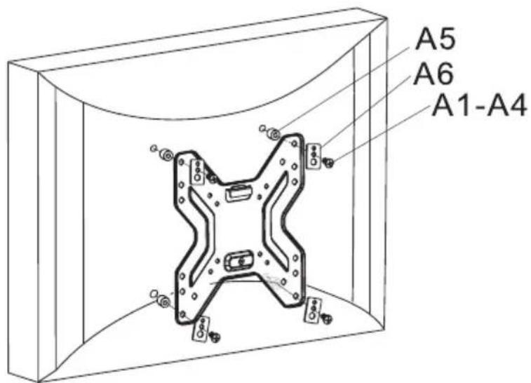
Warning: If the holes on the back of your TV are too shallow and none of the included screws fit into them, use the appropriate screws of your choice.
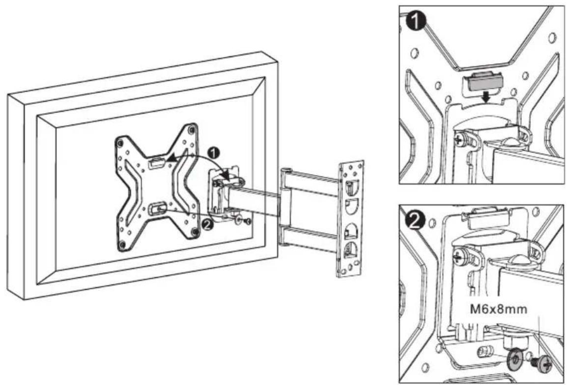
3 - Installing the adapter panel to the wall board
Mount the adapter panel to the wall arm so that the adapter flange is placed on the wall board rails. Tighten the M6 bolt on the wall board rails. Tighten the bolt firmly, but not too much.
4 - Cable fixing, tilt angle adjustment and tightening
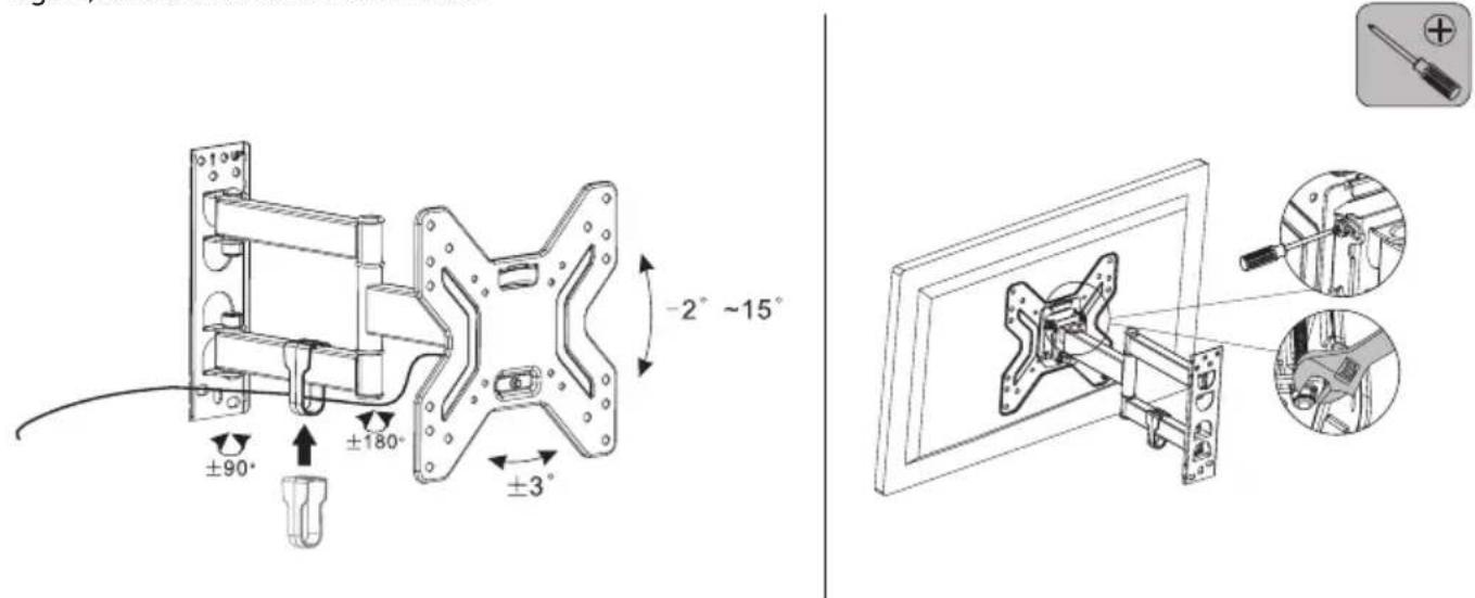
You can insert the wiring through the cable hole on the wall arm of the bracket. After pulling the cables through the hole, fit the enclosed cable organizer.
Loosen the screws on the wall arm plate to adjust the tilt angle of the TV as shown below. Loosen and tighten the screws using a Phillips screwdriver and wrench. After adjusting the desired angle, tighten the screws firmly again, but not with excessive force.
TECHNICAL SPECIFICATIONS
Panel size: 17" to 42"
Maximum TV weight: 25 kg
Compatibility: VESA 200×200
forward/back tilt: -2^ to +15^
Vertical axis rotation: 2 levels, ±90° and ±90°
Distance from the wall: 56–194 mm
USE AND DISPOSAL OF WASTE
Wrapping paper and corrugated paperboard – deliver to scrapyard. Packing foil, PE bags, plastic elements – throw into plastic recycling containers.
DISPOSAL OF PRODUCTS AT THE END OF LIFETIME
The represented symbol on the product or package means the product shall not be treated as domestic waste. Hand over the product to the specified location for recycling. Prevent negative impacts on human health and the environment by properly recycling your product. Recycling contributes to preserving natural resources. For more information on the recycling of this product, refer to your local authority, domestic waste processing organization or store, where you purchased the product.
The operating manual is available on internet at www.ecg-electro.eu.
Changes of text and technical parameters are reserved.
08/05
SICHERHEITSHINWEISE
TECHNISCHE ANGABEN
natural_image
Technical line drawing of a mechanical assembly with two components, one mounted on a frame and the other attached to a wall-mounted bracket (no text or symbols present)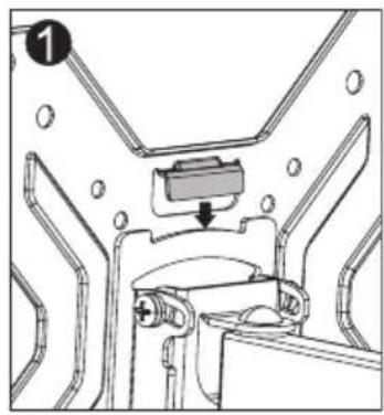
natural_image
Technical diagram of a mechanical assembly with no visible text or symbols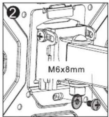
TECHNICKÉ ÚDAJE
natural_image
Technical line drawing of a mechanical assembly with two components, no visible text or symbols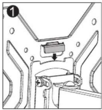
natural_image
Technical diagram of a mechanical assembly with no visible text or symbols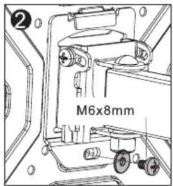
4 - Kaabli kinnitamine, kaldenurga reguleerimine ja pingutamine
TEHNILISED ANDMED
Panela lielums: 17–42 collas
Maksimālais televizora svars: 25 kg
Saderiba: VESA 200 × 200
BEZBEDNOSNA UPUTSTVA
natural_image
Technical line drawing of a mechanical assembly mounted on a wall-mounted frame, showing internal components and mounting bracket (no text or symbols)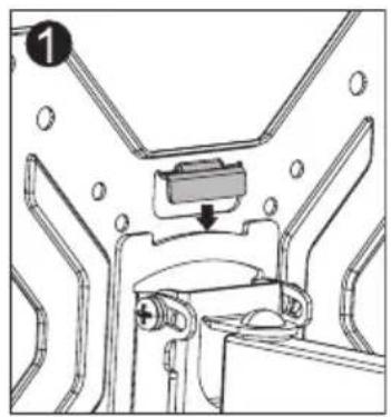
natural_image
Technical diagram of a mechanical assembly with no visible text or symbols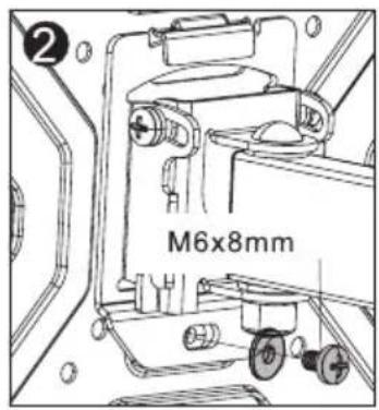
250 69 Klíčany, Czech Rep. e-post: ECG@kbexpert.cz
Hrvatski
K+B Progres, a.s.
U Expertu 91 tel.: +420 272 122 111
250 69 Klíčany, Czech Rep. e-mail: informacije@kbprogres.cz
Bosanski
K+B Progres, a.s.
U Expertu 91 tel.: +420 272 122 111
250 69 Kličany, Czech Rep. e-mail: informacije@kbprogres.cz
Latviešu valoda
K+B Progres, a.s.
U Expertu 91 tel.: +420 272 122 111
250 69 Klíčany, Czech Rep. e-pasts: ECG@kbexpert.cz
Lietuvių kalba
K+B Progres, a.s.
U Expertu 91 tel.: +420 272 122 111
250 69 Kličany, Czech Rep. el. paštas: ECG@kbexpert.cz
Magyar
K+B Progres, a.s.
U Expertu 91 tel.: +420 272 122 111
250 69 Kličany, Czech Rep. e-mail: ECG@kbexpert.cz
Polski
K+B Progres, a.s.
U Expertu 91 tel.: +420 272 122 111
250 69 Kličany, Czech Rep. e-mail: ECG@kbexpert.cz
Română
K+B Progres, a.s.
U Expertu 91 tel.: +420 272 122 111
250 69 Klíčany, Czech Rep. e-mail: ECG@kbexpert.cz
Slovenčina


- Read carefully and save for future use!
- DESCRIPTION
- ASSEMBLY
- 1A – Concrete wall assembly
- 1B – Wooden crossbar assembly
- 2A - Mounting the TV adapter panel to the TV with flat back
- 2B - Mounting the TV adapter panel to the TV with rounded back
- - Installing the adapter panel to the wall board
- - Cable fixing, tilt angle adjustment and tightening
- TECHNICAL SPECIFICATIONS
- USE AND DISPOSAL OF WASTE
- DISPOSAL OF PRODUCTS AT THE END OF LIFETIME
- SICHERHEITSHINWEISE
- TECHNISCHE ANGABEN
- TECHNICKÉ ÚDAJE
- - Kaabli kinnitamine, kaldenurga reguleerimine ja pingutamine
- TEHNILISED ANDMED
- BEZBEDNOSNA UPUTSTVA
- Hrvatski
- Bosanski
- Latviešu valoda
- Lietuvių kalba
- Magyar
- Polski
- Română
- Slovenčina
Brand : ECG
Model : LD 174202
Category : Uncategorized