
Bluehelix Maxima - Boiler FERROLI - Free user manual and instructions
Find the device manual for free Bluehelix Maxima FERROLI in PDF.


| Product Type | Condensing combi boiler (sealed chamber, premix) |
| Models | Bluehelix Maxima 24C, 28C, 34C |
| Dimensions (H x W x D) | 700 x 420 x 320 mm |
| Weight | 28 kg (24C, 28C), 32 kg (34C) |
| Power Supply | 230 V ~ 50 Hz |
| Electrical Power Input | 73 W (24C), 82 W (28C), 99 W (34C) |
| Max Heating Output (80/60°C) | 20.0 kW (24C), 24.0 kW (28C), 30.0 kW (34C) |
| Min Heating Output (80/60°C) | 2.8 kW (all models) |
| DHW Output (max) | 24.5 kW (24C), 28.0 kW (28C), 34.0 kW (34C) |
| DHW Flow Rate (ΔT 25°C) | 14.0 l/min (24C), 16.1 l/min (28C), 19.5 l/min (34C) |
| Gas Types | Natural gas (G20) and LPG (G31) |
| Efficiency (30% load) | 109.7% (24C, 28C), 109.5% (34C) |
| NOx Class | 6 (< 56 mg/kWh) |
| Protection Rating | IPX4D |
| Max Working Pressure (Heating) | 3.0 bar |
| Max Working Pressure (DHW) | 9.0 bar |
| Expansion Vessel Capacity | 8 L (24C, 28C), 10 L (34C) |
| Installation Environment | Indoor or partially protected outdoor (down to -5°C, -15°C with kit) |
| Maintenance Interval | Annual inspection by qualified personnel |
| Control Panel | Touchscreen with temperature adjustments, ECO mode, pressure display |
Frequently Asked Questions - Bluehelix Maxima FERROLI
User questions about Bluehelix Maxima FERROLI
0 question about this device. Answer the ones you know or ask your own.
Ask a new question about this device
Download the instructions for your Boiler in PDF format for free! Find your manual Bluehelix Maxima - FERROLI and take your electronic device back in hand. On this page are published all the documents necessary for the use of your device. Bluehelix Maxima by FERROLI.
USER MANUAL Bluehelix Maxima FERROLI
natural_image
3D rendering of a gray and black rectangular device with a central square cutout (no visible text or symbols)CE
IT
gauge
| Position | Current (A) | Voltage (V) | |---|---|---| | 1 | 1.2 | 32.5 | | 2 | 1.2 | 32.5 | | 3 | 1.2 | 32.5 | | 4 | 1.2 | 32.5 | | 5 | 1.2 | 32.5 | | 6 | 1.2 | 32.5 | | 7 | 1.2 | 32.5 | | 8 | 1.2 | 32.5 | | 9 | 1.2 | 32.5 | | 10 | 1.2 | 32.5 | | 11 | 1.2 | 32.5 | | 12 | 1.2 | 32.5 | | 13 | - | 32.5 | | 14 | - | 32.5 | | 15 | - | 32.5 | | 16 | - | 32.5 | | 17 | - | 32.5 | | 18 | - | 32.5 | | 19 | - | 32.5 | | 20 | - | 32.5 | | 21 | - | 32.5 | | 22 | - | 32.5 | | 23 | - | 32.5 | | 24 | - | 32.5 | | 25 | - | 32.5 | | 26 | - | 32.5 | | 27 | - | 32.5 | | 28 | - | 32.5 | | 29 | - | 32.5 | | 30 | - | 32.5 | | 31 | - | 32.5 | | 32 | - | 32.5 | | 33 | - | 32.5 | | 34 | - | 32.5 | | 35 | - | 32.5 | | 36 | - | 32.5 | | 37 | - | 32.5 | | 38 | - | 32.5 | | 39 | - | 32.5 | | 40 | - | 32.5 | | 41 | - | 32.5 | | 42 | - | 32.5 | | 43 | - | 32.5 | | 44 | - | 32.5 | | 45 | - | 32.5 | | 46 | - | 32.5 | | 47 | - | 32.5 | | 48 | - | 32.5 | | 49 | - | 32.5 | | 50 | - | 32.5 | | Note: The 'ON' label indicates the current value for position of the bar at the start of the gauge, but the 'Eco' label indicates the 'ECO' label at the end of the gauge, which is not explicitly provided in the image.fig. 1 -
natural_image
Technical line drawing of a mechanical assembly with gears and mounting base (no text or symbols)natural_image
Technical line drawing of a mechanical device with multiple ports and mounting brackets (no text or symbols)fig. 12

natural_image
Diagram of a mechanical assembly with a spring-loaded component and directional arrows indicating motion (no text or symbols)fig. 13
A = BLUEHELIX MAXIMA 24C
∅50 - 28 m MAX
∅60 - 78 m MAX
BLUEHELIX MAXIMA 28C
∅50 - 22 m MAX
∅60 - 60 m MAX
BLUEHELIX MAXIMA 34C
∅50 - 17 m MAX
∅60 - 45 m MAX
fig. 23
natural_image
Technical line drawing of a mechanical assembly with gears and a central motor (no text or symbols)natural_image
Technical line drawing of a mechanical device with multiple ports and mounting brackets (no text or symbols)fig. 12

natural_image
Diagram showing a mechanical assembly with a component inserted into a housing, indicated by arrows (no text or symbols present)fig. 13
A = BLUEHELIX MAXIMA 24C
∅50 - 28 m MAX
∅60 - 78 m MAX
BLUEHELIX MAXIMA 28C
∅50 - 22 m MAX
∅60 - 60 m MAX
BLUEHELIX MAXIMA 34C
∅50 - 17 m MAX
∅60 - 45 m MAX
natural_image
Technical diagram of a mechanical assembly with two views (1 and 2) showing internal components and motion arrows, no readable text or symbols present.fig. 23
gauge
| Pressure (Bar) | Value | | -------------- | ----- | | 0 | 0.4 | | 1.1 | 2.8 | | 2.8 | 4.0 | | 32.5 | 32.5 |fig. 9- Buton de umplere
natural_image
Technical line drawing of a mechanical assembly with gears and components (no visible text or symbols)natural_image
Technical line drawing of a mechanical device with multiple ports and mounting brackets (no text or symbols)fig. 12
natural_image
Diagram showing a mechanical assembly with a spring-loaded component and a separate box, no text or symbols present.fig. 13
A = BLUEHELIX MAXIMA 24C
∅50 - 28 m MAX
∅60 - 78 m MAX
BLUEHELIX MAXIMA 28C
∅50 - 22 m MAX
∅60 - 60 m MAX
BLUEHELIX MAXIMA 34C
∅50 - 17 m MAX
∅60 - 45 m MAX
fig. 23
Verificarea valorilor de combustie
ASIGURATI-VĂ CĂ PANOUL FRONTAL ESTE ÎNCHIS, IAR CONDUCTELE DE ASPIRATIE/EVACUARE GAZE ARSE SUNT ASAMBLATE COMPLET.
line
| Date | Value | | ---------- | ----- | | 20100-10-20 | 30 | | 20100-10-19 | 35 | | 20100-10-18 | 40 | | 20100-10-17 | 45 | | 20100-10-16 | 50 | | 20100-10-15 | 55 | | 20100-10-14 | 60 | | 20100-10-13 | 65 | | 20100-10-12 | 70 | | 20100-10-11 | 75 | | 20100-10-10 | 80 | | 20100-10-09 | 85 | | 20100-10-08 | 90 |fig. 25- Curbe de compensare
line
| x | y | |----|------| | 20 | 20 | | 10 | 40 | | 0 | 60 | | -10| 70 | | -20| 80 |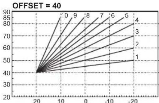
line
| x | y | |----|------| | 20 | 40 | | 10 | 85 | | 0 | 70 | | -10| 60 | | -20| 50 |line
| Q (m3/h) | H(mCA) | | -------- | ------ | | 0.0 | 7.8 | | 0.2 | 7.6 | | 0.4 | 7.4 | | 0.6 | 7.2 | | 0.8 | 7.0 | | 1.0 | 6.8 | | 1.2 | 6.5 | | 1.4 | 6.2 | | 1.6 | 5.9 | | 1.8 | 5.5 | | 2.0 | 5.0 | | 2.2 | 4.5 | | 2.4 | 4.0 | | 2.6 | 3.5 | | 2.8 | 3.0 | | 3.0 | 2.5 | | 3.2 | 2.0 | | 3.4 | 1.5 | | 3.6 | 1.0 | | 3.8 | 0.5 | | 4.0 | 0.0 |natural_image
Technical line drawing of a mechanical assembly with labeled component '1' (no readable text or symbols)natural_image
Technical line drawing of a mechanical device with multiple ports and mounting brackets (no text or symbols)wygląd 1 2

natural_image
Diagram of a mechanical assembly with a component inserted into a housing, showing directional arrows (no text or symbols)wygląd 1 3
A = BLUEHELIX MAXIMA 24C
∅50 - 28 m MAX
∅60 - 78 m MAX
BLUEHELIX MAXIMA 28C
∅50 - 22 m MAX
∅60 - 60 m MAX
BLUEHELIX MAXIMA 34C
∅50 - 17 m MAX
∅60 - 45 m MAX
wygląd 2 3
line
| Date | Value | | :--- | :--- | | 2010-10-20 | 30 | | 2010-10-21 | 35 | | 2010-10-22 | 40 | | 2010-10-23 | 45 | | 2010-10-24 | 50 | | 2010-10-25 | 55 | | 2010-10-26 | 60 | | 2010-10-27 | 65 | | 2010-10-28 | 70 | | 2010-10-29 | 75 | | 2010-10-30 | 80 | | 2010-10-31 | 85 | | 2010-11-01 | 90 | The chart displays a single data series (line) with values ranging from 30 to 90. The x-axis represents time in months (from October 10 to October 20). There are no y-axis label or legend provided in the image.- Read the warnings in this instruction booklet carefully since they provide important information on safe installation, use and maintenance.
- This instruction booklet is an integral and essential part of the product and must be kept with care by the user for future reference.
- If the unit is sold or transferred to another owner or if it is to be moved, always make sure the booklet stays with the boiler so that it can be consulted by the new owner and/or installer.
• Installation and maintenance must be carried out by professionally qualified per-
sonnel, according to current regulations and the manufacturer's instructions.
- Incorrect installation or inadequate maintenance can result in damage or injury. The manufacturer declines any liability for damage caused by errors in installation and use or by failure to follow the instructions provided.
- Before carrying out any cleaning or maintenance operation, disconnect the unit from the power supply using the system switch and/or the special cut-off devices.
• In case of a fault and/or poor operation, deactivate

This symbol indicates “CAUTION” and is placed next to all safety warnings. Strictly follow these instructions in order to avoid danger and damage to persons, animals and things

This symbols calls attention to a note or important notice.

This symbol, which is used on the product, packaging or documents, means that at the end of its useful life, this product must not be collected, recycled or disposed of together with domestic waste.
Improper management of electric or electronic waste can lead to the leakage of hazardous substances contained in the product. For the purpose of preventing damage to health or the environment, users are kindly asked to separate this equipment from other types of waste and to ask for it to be dealt with by the municipal waste service or dealer under the conditions and according to the methods set down in national and international laws transposing the Directive 2012/19/EU.
Separate waste collection and recycling of unused equipment helps to save natural resources and to guarantee that this waste is processed in a manner that is safe for health and the environment.
For more information about how to collect electric and electronic equipment and appliances, please contact your local Council or Public Authority competent to issue the relevant permits.

The CE marking certifies that the products meet the essential requirements of the relevant directives in force.
The declaration of conformity may be requested from the manufacturer.
COUNTRIES OF DESTINATION: IT - ES - RO - PL

the unit and do not try to re-pair it or directly intervene. Contact professionally qualified personnel. Any repair/replacement of the products must only be carried out by qualified personnel using genuine parts. Failure to comply with the above can compromise the safety of the unit.
- Periodic maintenance performed by qualified personnel is essential in order to ensure proper operation of the unit.
- This unit must only be used for its intended purpose. Any other use is deemed improper and therefore hazardous.
• After unpacking, check the good condition of the contents. The packing materials are potentially hazardous and must not be left within the reach of children.
- The unit can be used by children aged at least 8 years and by persons with reduced physical, sensory or mental capabilities, or lacking experience or the
necessary knowledge, only if under supervision or they have received instructions on its safe use and the related risks. Children must not play with the unit. Cleaning and maintenance intended to be done by the user can be carried out by children aged at least 8 years only if under supervision.
- In case of doubt, do not use the unit. Contact the supplier.
- The unit and its accessories must be appropriately disposed of in compliance with current regulations.
- The images given in this manual are a simplified representation of the product. In this representation there may be slight and insignificant differences with respect to the product supplied.
1 Operating instructions .... 192
1.1 Introduction....192
1.2 Control panel....192
1.3 Connection to the power supply, switching on and off 193
1.4 Adjustments.... 193
2 Installation....198
2.1 General Instructions 198
2.2 Place of installation 198
2.3 Plumbing connections 198
2.4 Gas connection 200
2.5 Electrical connections....200
2.6 Fume ducts....203
2.7 Condensate drain connection....209
3 Service and maintenance....210
3.1 Adjustments....210
3.2 Commissioning....217
3.3 Maintenance....218
3.4 Troubleshooting....221
4 Technical data and characteristics 225
4.1 Dimensions and connections 225
4.2 General view 228
4.3 Hydraulic circuit 228
4.4 Technical data table 229
4.5 Diagrams 233
4.6 Wiring diagram (fig. 46)....233
1. Operating instructions
1.1 Introduction
Dear Customer,
BLUEHELIX MAXIMA is a high-efficiency, low emissions premix condensing heat generator with heat exchanger in s/steel and incorporated DHW production, using natural gas or LPG and equipped with a microprocessor control system.
The sealed chamber unit is suitable for indoor installation or outdoors in a partially protected place (according to EN 15502) with temperatures to -5°C (-15°C with optional frost protection kit).
1.2 Control panel

gauge
| Value | Label | |---|---| | 32.5° | 32.5° | | 28.5° | 28.5° | | 1.2 Bar | 1.2 Bar | | ON | ON | | ECO | ECO | | ? | ? |fig. 1-
- User menu
- Connection status
- Pressure status
- System pressure
- ECO mode on/off
- Date and time
- Flame present in DHW mode
- Flame present in Heating mode
- DHW temperature
10.Heating temperature
11.Increase DHW temperature - Increase Heating temperature
- Decrease DHW temperature
- Decrease Heating temperature
- Boiler on/off selection
- Heating on/off selection
17.Help
Flame status table

A flame not present
B boiler on
C boiler blocked for failed ignition
D calibration in progress
1.3 Connection to the power supply, switching on and off
Boiler not electrically powered

To avoid damage caused by freezing during long idle periods in winter, it is advisable to drain all the water from the boiler.
Boiler electrically powered
Switch on the power to the boiler.
- During the first 5 seconds a screen appears giving the PCB firmware versions at the bottom.
- For the next 300 seconds the screen shows the progress of the heating system air venting cycle.
- At the end of the venting process, check that the gas cock ahead of the boiler is open.
To prevent the air venting cycle during boiler ignition, press and hold the words "BLUEHELIX MAXIMA" (about 10 seconds) until the main screen appears.
Activation of boiler operating modes
Heating can be enabled or disabled using the ON/OFF button (16 in fig. 1). When both are disabled (15 and 16 in fig. 1) the boiler is off but still electrically powered.
With the heating mode deactivated the frost protection function still remains active.

The frost protection system does not work when the power and/or gas to the unit are turned off. To avoid damage caused by freezing during long shutdowns in winter, it is advisable to drain all water from the boiler, the DHW circuit and the heating system water; or drain just the DHW circuit and add a suitable antifreeze to the heating system, as prescribed in sec. 2.3.
1.4 Adjustments
By touching the control "B" (fig. 2 and fig. 3) it is possible to enable (ON) or disable (DHW)Disabling DHW also automatically inhibits the heating function.

gauge
| Value | | --------- | | 32.5° |Enable/Disable the heating function
By touching the control “A” (fig. 4 and fig. 5) it is possible to enable (ON) or disable (HEATING).

fig. 4- Heating function active

fig. 5- Heating function not active
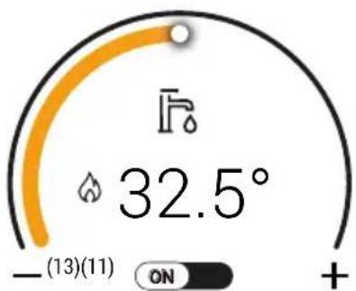
DHW temperature adjustment
Use the DHW icons (details 11 and 13 - fig. 6) to adjust the temperature from a min. of 35°C to a max. of 55°C.
If little water is drawn off and/or with a high water inlet temperature, the DHW outlet temperature may differ from the set temperature.
gauge
| Metric | Value | |--------|-----------| | Current | 32.5° | | Change | -13(11) |Heating temperature adjustment
Use the heating buttons (details 12 and 14 - fig. 7) to adjust the temperature from a min. of 20^ C to a max. of 80^ C.

gauge
| Metric | Value | |--------|-------| | Current | 28.5° | | ON | | | + | |fig. 7- Heating adjustment
Room temperature adjustment with timer control

As far as possible, make all settings using the room temperature adjustment device. Regarding the timer, refer to the relevant user manual.
ECO mode
The ECO mode minimizes energy consumption, but it may take longer for the DHW to reach the required temperature.
With the ECO mode disabled, the temperature of water inside the boiler is maintained, thereby ensuring immediate availability of hot water.
Restoring system hydraulic pressure
The boiler provides for various ways of restoring the hydraulic system. pressure. Manual, always available, or semiautomatic or automatic depending on the parameter value P62.
"Pressure control" screen
To access the pressure control screen, simply touch the pressure value (detail 4 - fig. 1) on the main screen.
Description of "Pressure control" screen

gauge
| Value | |-------| | 0 | | 1.1 | | 2.8 | | 4.0 |fig. 8- Pressure control
Legend fig. 8
1 Back to main screen
2 Pressure status indicator (see attached table)
3 Boiler operating pressure zone
4 Pressure zone too high (boiler blocked)
5 Current pressure indicator
6 Current pressure value
7 Pressure zone too low, boiler operation inhibited
8 Pressure reset button (enabled in semiautomatic mode)
9 Nominal pressure indicator
| Icon Fault | code Description | |
 | F40 Pressure too high for boiler operation | |
| RED | ||
 | F21 | Pressure higher than nominal valueThe boiler works at limited output |
| YELLOW | ||
 | NONE Pressure at nominal value | |
| GREEN | ||
 | F20 | Pressure lower than nominal valueThe boiler continues to work normally |
| YELLOW | ||
 | F37 Pressure too low for boiler operation | |
| RED | ||
System hydraulic pressure manual reset
The filling pressure read on the boiler water gauge (detail 2 - fig. 9) with system cold must be approx 1.0 bar. The boiler stops if the system pressure drops to values below the minimum. Pull out the filling knob (detail 1 - fig. 9) and turn it anticlockwise to return it to the initial value. Always close it afterwards.
Once the system pressure is restored, the boiler will activate the 300-second air venting cycle, identified on the display with the appropriate sequence of screens.
To prevent boiler shutdown, it is advisable to periodically check the pressure on the gau-
ge with system cold. In case of a pressure below 0.8 bar, it is advisable to restore it.

fig. 9- Filling knob
System semiautomatic pressure restoration (P62 = 0)
In case of low water pressure (indicated by the symbol), access the pressure control screen (fig. 8) and press the "RESTORE" button.
This activates the filling valve until the pressure returns to the nominal value (P57) +0.4 bar.
If the nominal pressure is not reached within a time limit (4 min), a shutdown is generated (A23).
System automatic pressure restoration (P62 = 1)
If the boiler detects a too low system pressure, the filling valve is automatically activated until the nominal value is reached (P57) +0.4 bar.
If the nominal pressure is not reached within a time limit (4 min), a shutdown is generated (A23).
System draining
The drain faucet ring nut is located under the safety valve inside the boiler.
To drain the system, turn the ring (ref. 1 - fig. 10) counter-clockwise to open the faucet. Do not use any tools; use hands only.
To drain only the water in the boiler, first close the shut-off valves between the system and boiler before turning the ring.

natural_image
Technical line drawing of a mechanical assembly with gears and components (no text or symbols)fig. 10- Safety valve with drain faucet
Settings menu

1 Back to main screen
2 Faults history
3 Number of faults not read since last access to history
4 Activate screen lock for glass cleaning
5 Current language
6 Language selection
7 Display behavior management
8 LED behavior management
9 Set date and time
10 Probe and sensor information
11 Boiler reset
12 Installer menu
2. Installation
2.1 General Instructions
BOILER INSTALLATION MUST ONLY BE PERFORMED BY QUALIFIED PERSONNEL, IN ACCORDANCE WITH ALL THE INSTRUCTIONS GIVEN IN THIS TECHNICAL MANUAL, THE PROVISIONS OF CURRENT LAW, THE PRESCRIPTIONS OF NATIONAL AND LOCAL STANDARDS AND THE RULES OF PROPER WORKMANSHIP.
2.2 Place of installation

The combustion circuit is sealed with respect to the place of installation and therefore the unit can be installed in any room except in a garage. The place of installation must be sufficiently ventilated to prevent the creation of dangerous conditions in case of even small gas leaks. Otherwise there may be a risk of suffocation and intoxication or explosion and fire. This safety precaution is required by EEC Directive No. 2009/142 for all gas units, including so-called sealed chamber units.
The unit is designed to operate in a partially protected place, with a minimum temperature of -5^ . If provided with the special antifreeze kit, it can be used with a minimum temperature down to -15^ . The boiler must be installed in a sheltered place, for instance under the slope of a roof, inside a balcony or in a protected recess.
The place of installation must be free of flammable materials, objects and dusts or corrosive gases.
The boiler is arranged for wall mounting and comes as standard with a hooking bracket. Wall fixing must ensure stable and effective support for the generator.

If the unit is enclosed in a cabinet or mounted alongside, there must be sufficient space for removing the casing and for normal maintenance activities
2.3 Plumbing connections
Important

The safety valve outlet must be connected to a funnel or collection pipe to prevent water spurting onto the floor in case of overpressure in the heating circuit. Otherwise, if the discharge valve cuts in and floods the room, the boiler manufacturer cannot be held liable.

Before installation, flush all the pipes of the system thoroughly to remove any residuals or impurities that could affect proper operation of the unit.
In case of replacement of generators in existing installations, the system must be completely emptied and cleaned of any sludge and pollutants. For that purpose only
use suitable guaranteed products for heating systems (see next section), that do not harm metals, plastics or rubber. The manufacturer declines any liability for damage caused to the generator by failure to properly clean the system.
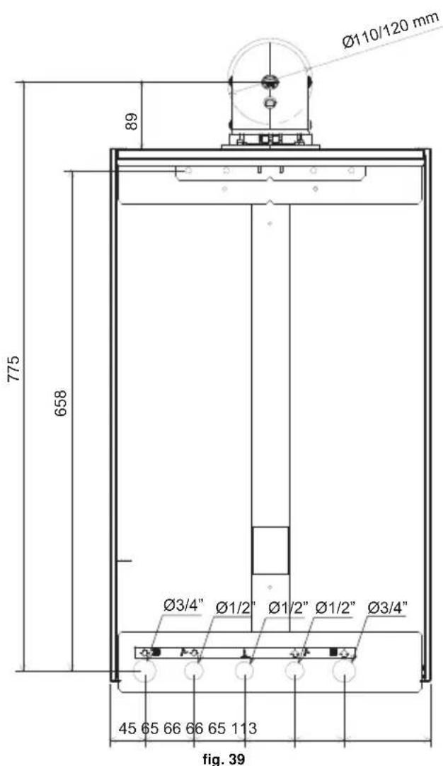
Make the connections to the respective points (see fig. 38, fig. 39 and fig. 40) and to the symbols given on the unit.
Antifreeze system, antifreeze fluids, additives and inhibitors
When necessary, antifreeze fluids, additives and inhibitors can be used only if the manufacturer of such fluids or additives guarantees that they are suitable and do not cause damage to the exchanger or other components and/or materials of the boiler and system. Do not use generic antifreeze fluids, additives or inhibitors that are not specific for use in heating systems and compatible with the materials of the boiler and system.
System water characteristics

BLUEHELIX MAXIMA boilers are suitable for installation in heating systems with non-significant entry of oxygen (ref. systems "case I" EN14868). A physical separator (e.g. plate heat exchanger) must be provided in systems with continuous entry of oxygen (e.g. underfloor systems without antidiffusion pipes or open vessel), or intermittent (less than 20% of system water content).
The water within a heating system must have the characteristics required by UNI 8065, and comply with laws and regulations in force and the provisions of EN14868 (protection of metallic materials against corrosion).
The filling water (first filling and subsequent replenishment) must be clear, with hardness below 15^ F and treated with suitable chemical conditioners against the initiation of corrosion, that are not aggressive on metals and plastics, do not develop gases and, in low-temperature systems, do not cause proliferation of bacterial or microbial masses.
The water in the system must be periodically checked (at least twice a year during the season when the systems are used, as required by UNI8065) and have: possibly a clear appearance, hardness below 15^ F for new systems or 20^ F for existing systems, pH above 7 and below 8.5, iron content (Fe) below 0.5 mg/l, copper content (Cu) below 0.1 mg/l, chloride content below 50mg/l, electrical conductivity below 200 s/cm, and must contain chemical conditioners in a concentration sufficient to protect the system for at least one year. Bacterial or microbial loads must not be present in low temperature systems.
Only use conditioners, additives, inhibitors and antifreeze liquids declared by the producer suitable for use in heating systems and that do not cause damage to the heat exchanger or other components and/or materials of the boiler and system.
Chemical conditioners must ensure complete deoxygenation of the water, contain specific protection for yellow metals (copper and its alloys), anti-fouling agents for scale, neutral pH stabilizers and, in low-temperature systems, specific biocides for use in heating systems.
Recommended chemical conditioners:
SENTINEL X100 and SENTINEL X200
FERNOX F1 and FERNOX F3
The unit is equipped with a frost protection system that activates the boiler in heating mode when the system delivery water temperature falls below 6^ C. The device is not active if the power and/or gas supply to the unit is turned off. If necessary, for system protection use a suitable antifreeze liquid that meets the same requirements as set out above and provided for by Standard UNI 8065.
In the presence of adequate chemical/physical system and feed water treatments and related high cyclicity controls able to ensure the required parameters, for industrial process applications the product can be installed in open-vessel systems with vessel hydrostatic height able to ensure compliance with the minimum operating pressure indicated in the product technical specifications.
The presence of deposits on the boiler exchange surfaces due to non-compliance with the above requirements will involve non-recognition of the warranty.
Frost protection kit for outdoor installation (optional - 013022X0)
In case of installation outdoors in a partially protected place, for temperatures below -5^ and down to -15^ , the boiler must be fitted with the special frost protection kit. For proper installation, please refer to the instructions in the kit.
2.4 Gas connection

Before making the connection, ensure that the unit is arranged for operation with the type of fuel available.
The gas must be connected to the corresponding union (see fig. 38) in conformity with current regulations, with a rigid metal pipe or with a continuous flexible s/steel tube, installing a gas cock between the system and boiler. Make sure that all the gas connections are tight. Otherwise there may be a risk of fire, explosion or suffocation.
2.5 Electrical connections
IMPORTANT

BEFORE CARRYING OUT ANY OPERATION THAT RE- QUIRES REMOVING THE CASING, DISCONNECT THE BOILER FROM THE ELECTRIC MAINS WITH THE MAIN SWITCH.
NEVER TOUCH THE ELECTRICAL COMPONENTS OR CONTACTS WITH THE MAIN SWITCH TURNED ON! DANGER OF ELECTRIC SHOCK WITH RISK OF INJURY OR DEATH!

The unit must be connected to an efficient grounding system in accordance with applicable safety regulations. Have the efficiency and suitability of the grounding system checked by professionally qualified personnel; the Manufacturer declines any liability for damage caused by failure to earth the system.
The boiler is prewired and provided with a three-pole cable, without a plug, for connection to the electric line. The
connections to the grid must be made with a permanent connection and equipped with a bipolar switch whose contacts have a minimum opening of at least 3 mm, interposing fuses of max. 3A between the boiler and the line. Make sure to respect the polarities (LINE: brown wire / NEUTRAL: blue wire / GROUND: yellow-green wire) in the connections to the electric line.

The unit's supply cable MUST NOT BE REPLACED BY THE USER. If the cable gets damaged, turn the unit off and have the cable replaced only by professionally qualified personnel. In case of replacement, only use cable “HAR H05 VV-F” 3x0.75 mm2 with max. external diameter of 8 mm.
Room thermostat

ATTENTION: THE ROOM THERMOSTAT MUST HAVE VOLTAGE-FREE CONTACTS. CONNECTING 230V TO THE ROOM THERMOSTAT TERMINALS WILL PERMA-NENTLY DAMAGE THE PCB.
When connecting a time control or timer, do not take the power supply for such devices from their cutoff contacts. Their power supply must be via a direct connection from the grid or with batteries, depending on the kind of device.
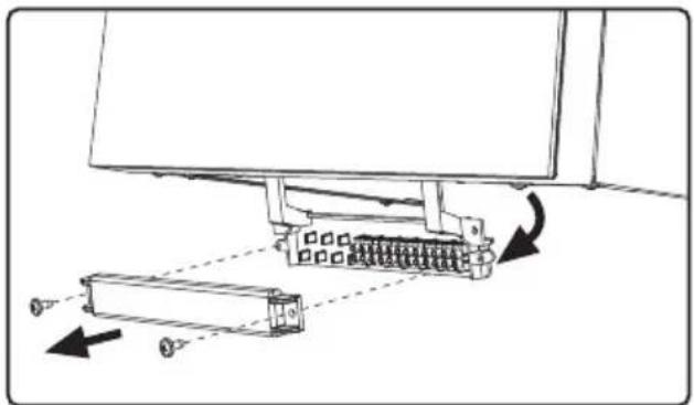
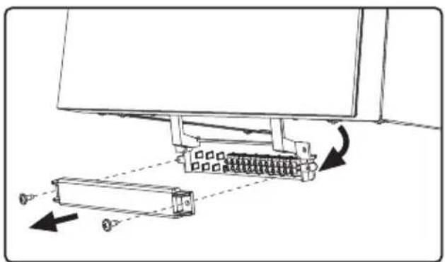
Accessing the electrical terminal block
The terminal block can be accessed by following the instructions given below (fig. 12 and fig. 13). The arrangement of terminals for the various connections is given in the wiring diagram in fig. 46.
The terminals must be with voltage-free contacts (not 230V).

natural_image
Technical line drawing of a mechanical device with multiple ports and mounting brackets (no text or symbols)fig. 12
natural_image
Diagram of a mechanical assembly with a spring-loaded component and directional arrows indicating motion (no text or symbols)fig. 13
Terminal block auxiliary input configuration
Table 1- Auxiliary input settings
| DHW configuration Parameter b06 | |
| b01 = RRT | b06=0 Contact open disables DHW and re-enables it if closed. |
| b06=1 If the contact is open, it disables heating and displays F50. Contact closed enables heating. | |
| b06=2 The contact acts as a room thermostat. | |
| b06=3 If the contact is open, it displays F51 and the boiler continues to work. It is used as an alarm. | |
| b06=4 The contact functions as a limit thermostat, if open it displays F53 and deactivates the request. | |
2.6 Fume ducts
THE BOILERS MUST BE INSTALLED IN ROOMS THAT MEET THE FUNDAMENTAL VENTILATION REQUIREMENTS. OTHERWISE THERE IS DANGER OF SUFFOCATION OR INTOXICATION. READ THE INSTALLATION AND MAINTENANCE INSTRUCTIONS BEFORE INSTALLING THE UNIT. ALSO FOLLOW THE DESIGN INSTRUCTIONS. IN CASE OF PRESSURES ABOVE 200 Pa INSIDE THE FUME EXHAUST PIPES, CLASS "H1" FLUES MUST BE USED.
Important
The unit is “type C” with sealed chamber and forced draught; the air inlet and fume outlet must be connected to one of the following extraction/suction systems. Before installation, check and carefully observe the above prescriptions. Also, comply with the provisions concerning the positioning of wall and/or roof terminals and the minimum distances from windows, walls, vents, etc.
Installation type C10
In case of flues under pressure in a collective flue, before installation and at subsequent maintenance operations, close the fume discharge duct coming from the flue. OTHERWISE THERE IS DANGER OF SUFFOCATION DUE TO PRODUCTS OF COMBUSTION ESCAPING INTO THE BOILER ROOM.
Installation of the boiler according to type C10 must be carried out by specialist personnel doing the calculations required by current regulations in compliance with the maximum positive pressure of the flue and the boiler.
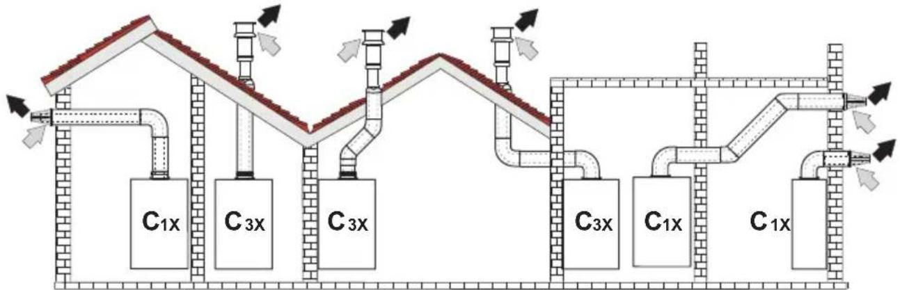
Connection with coaxial pipes
flowchart
graph TD
    A["C1x"] --> B["C3x"]
    B --> C["C3x"]
    C --> D["C3x"]
    D --> E["C3x"]
    E --> F["C1x"]
    F --> G["C1x"]
    G --> H["C1x"]
    H --> I["C1x"]
    I --> J["C1x"]
    style A fill:#f9f,stroke:#333
    style B fill:#f9f,stroke:#333
    style C fill:#f9f,stroke:#333
    style D fill:#f9f,stroke:#333
    style E fill:#f9f,stroke:#333
    style F fill:#f9f,stroke:#333
    style G fill:#f9f,stroke:#333
    style H fill:#f9f,stroke:#333
    style I fill:#f9f,stroke:#333
    style J fill:#f9f,stroke:#333
fig. 14 - Examples of connection with coaxial pipes (≡ Air / = Frames)
For coaxial connection, fit the unit with one of the following starting accessories. For the wall drilling dimensions refer to the figures fig. 39, fig. 40 and fig. 41. Any horizontal sections of the fume exhaust must be kept sloping slightly towards the boiler, to prevent possible condensate from flowing back towards the outside and causing dripping.


fig. 15- Starting accessories for coaxial ducts
Table 2- Max. length coaxial ducts
| Coaxial 60/100 Coaxial 80/125 | ||
| Max. permissible length (horizontal) 7 m | 20 m | |
| Max. permissible length (vertical) 8 m | ||
| Reduction factor 90° bend 1 m 0.5 m | ||
| Reduction factor 45° bend 0.5 m 0.25 m | ||
Connection with separate pipes

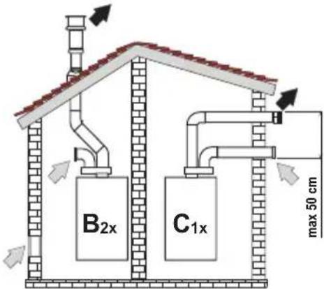
fig. 16- Examples of connection with separate pipes (= Air / = Frames)
Table 3 - Typology
| Type Description | |
| C1X | Wall horizontal exhaust and intake. The inlet/outlet terminals must be concentric or close enough to be undergo similar wind conditions (within 50 cm) |
| C3X Roof vertical exhaust and intake. Inlet/outlet terminals like for C12 | |
| C5X | Wall or roof exhaust and intake separate or in any case in areas with different pressures. The exhaust and intake must not be positioned on opposite walls. |
| C6X Intake and exhaust with separately certified pipes (EN 1856/1) | |
| B2X Intake from installation room and wall or roof exhaustIMPORTANT - THE ROOM MUST BE PROVIDED WITH APPROPRIATE VENTILATION | |
For the connection of separate ducts, fit the unit with the following starting accessory:
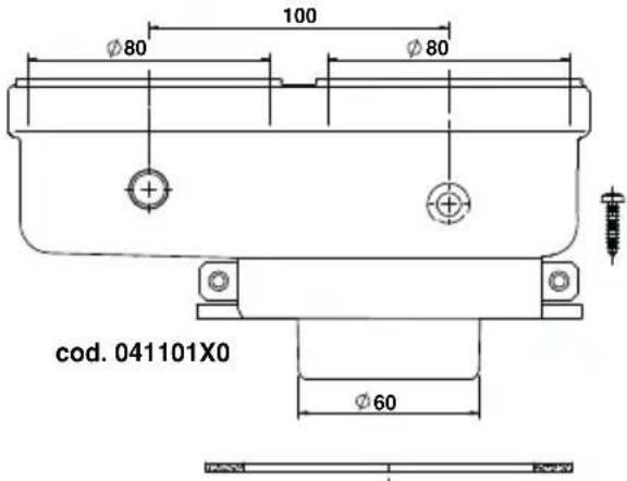
fig. 17- Starting accessory for separate ducts
Before installation, make sure the maximum permissible length has not been exceeded by means of a simple calculation:
- Establish the layout of the system of split flues, including accessories and outlet terminals.
- Consult table 5 and identify the losses in m_eq (equivalent meters) of every component, according to the installation position.
- Check that the sum total of losses is less than or equal to the maximum permissible length in table 4.
Table 4- Max. length separate ducts
| Max. permissible length BLUEHELIX MAXIMA 24C80 m_eq | BLUEHELIX MAXIMA 28C and BLUEHELIX MAXIMA 34C70 m_eq |
Table 5- Accessories
| Losses in m_eq | ||||||
| Air intake | Fume exhaust | |||||
| Vertical Horizontal | ||||||
| ∅ 80 | PIPE 1 | m M/F 041104X0 1.0 1.6 2.0 | ||||
| BEND 4 | 5° M/F 041103X0 1.2 1.8 | |||||
| 90° M/F 041102X0 1.5 2.0 | ||||||
| PIPE SECTION with test point 1KWMA70W 0.3 0.3 | ||||||
| TERMINAL air, wall 1KWMA85A 2.0 - | ||||||
| fumes, wall with antiwind 1KWMA86A - 5.0 | ||||||
| FLUE | Split air/fumes 80/80 | 010027X0 | - | 12.0 | ||
| Fume outlet only ∅80 | 010026X0 + 1KWMA86U | - | 4.0 | |||
| ∅ 60 | PIPE 1 | m M/F 1KWMA89W | 6.0 | |||
| BEND 9 | 0° M/F 1KWMA88W | 4.5 | ||||
| REDUCER | 80/60 | 041050X0 | 5.0 | |||
| TERMINAL | fumes, wall with antiwind | 1KWMA90A | 7.0 | |||
| ∅ 50 | PIPE 1 | m M/F 041086X0 | 12 | |||
| BEND | 90° M/F | 041085X0 | 9 | |||
| REDUCER | 80/50 | 041087X0 | 10 | |||
 | ATTENTION: CONSIDER THE HIGH PRESSURE LOSSES OF ∅50 and ∅60 ACCESSORIES; USE THEM ONLY IF NECESSARY AND AT THE LAST FUME EXHAUST SECTION. | |||||
Use of ∅50 and ∅60 flexible pipe (for ducting only)
The chart includes the starting accessories code 041087X0 for ∅50 and code 041050X0 for ∅60. Up to 4 m. of ∅80 mm flue can be used between the boiler and the passage with reduced width (∅50 or ∅60), and up to 4 m. of ∅80 mm flue on the intake (with max. length of ∅50 and ∅60 flues).

fig. 18
A = BLUEHELIX MAXIMA 24C
∅50 - 28 m MAX
∅60 - 78 m MAX
BLUEHELIX MAXIMA 28C
∅50 - 22 m MAX
∅60 - 60 m MAX
BLUEHELIX MAXIMA 34C
∅50 - 17 m MAX
∅60 - 45 m MAX
To use this width, follow the instructions below.
Enter the menu SC (follow the instructions given in par. "Combustion Control Menu" on page 216) and set the parameter SC04 to the value corresponding to the length of flue used.
For model BLUEHELIX MAXIMA 24C/ For model BLUEHELIX MAXIMA 28C/ For model BLUEHELIX MAXIMA 34C

fig. 19- Chart for flue parameter choice
Connection to collective flues

fig. 20- Examples of connection to collective flues (= Air / = Frames)

fig. 21- Connection examples - system C10 and C11 (= Air / = Frames)
Table 6- Typology
| Type Description | |
| C10 | Unit connected through its ducts to a system of common flue pipes under pressure obtained in the structure |
| C11 Unit | connected through its ducts to a system of common flue pipes under pressure |
| C2X Intake and exhaust in common flue (intake and exhaust in same flue) | |
| C4X | Intake and exhaust in common and separate flues, but undergoing similar wind conditions |
| C8X Exhaust in single or common flue and wall intake | |
| B3X | Intake from installation room by means of concentric duct (that encloses the exhaust) and exhaust in common flue with natural draftIMPORTANT- THE ROOM MUST BE PROVIDED WITH APPROPRIATE VENTILATION |
| C93 Exhaust to a vertical terminal and intake from existing flue. | |
If the boiler is to be connected BLUEHELIX MAXIMA to a collective flue or to a single flue with natural draft, the flue or chimney must be expressly designed by professionally qualified technical personnel in conformity with current regulations and be suitable for sealed chamber units equipped with fan.
ONLY FOR THE ITALIAN MARKET
According to Art. 5 Para. 2, f) and g) of Min. Decree 37/08, gas systems, chimneys, flues and smoke systems with a capacity of over 50 kW and in any case all multiple flues installed in Italy must be designed by a Professional registered in the appropriate professional registers.
Backflow preventer valve
The boiler BLUEHELIX MAXIMA is equipped as standard with a backflow preventer valve (anti-backflow system), therefore it can be connected to a positive pressure collective flue system, only if using G20 gas.
In case of C10-type boiler installation, apply the relevant white adhesive plate (included in the document bag supplied with the unit) in a CLEARLY VISIBLE PLACE on the FRONT PANEL.
After installation, check the tightness of the fumes and gas circuit.
OTHERWISE THERE IS DANGER OF SUFFOCATION DUE TO THE EMISSION OF COMBUSTION FUMES.
2.7 Condensate drain connection
IMPORTANT
The boiler has an internal trap for draining condensate. Install the hose “B” by pressing it into place. Before commissioning, fill the trap with approx. 0.5 L of water and connect the hose to the disposal system.
Drains connected to the drainage system must be resistant to acidic condensate.
If the condensate drain is not connected to the waste water drainage system, a neutralizer must be installed.

ATTENTION: THE UNIT MUST NEVER BE OPERATED WITH THE TRAP EMPTY!
OTHERWISE THERE IS A DANGER OF SUFFOCATION DUE TO THE EMISSION OF COMBUSTION FUMES.
THE CONDENSATE DRAIN MUST BE CONNECTED TO THE DRAINAGE SYSTEM IN SUCH A WAY THAT THE LIQUID CONTAINED CANNOT FREEZE.

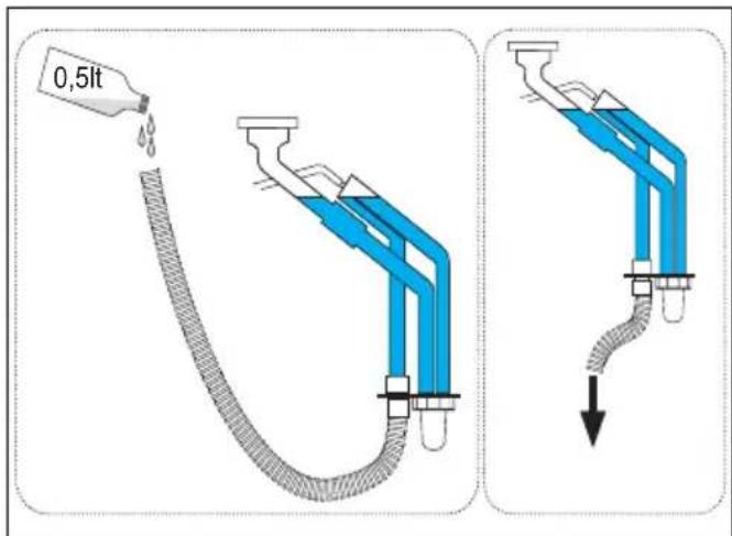
fig. 22- Condensate drain connection
3. Service and maintenance
3.1 Adjustments
Gas conversion
The unite can use gas of the 2^nd or 3^rd family as clearly indicated on the packaging and on the unit's technical data plate. If the unit has to be used with a gas other than the factory-set one, proceed as follows:
- Disconnect the power supply and turn off the gas.
- Remove the front panel (see *** 'Opening the front panel' on page 219 ***)
- Turn the Throttle (fig. 23) according to the position indicated in table 7.
- Apply the plate for LPG (contained in the document bag) near the technical data plate.
- Refit the front panel and turn on the power to the boiler.
-
Modify the parameter for the type of gas:
-
Access the user menu
- Access the [ service menu] and press confirm
- Enter the password "1234" and confirm []
- Select [Combustion Control]
- select the parameter [1/Gas type selection]
- Press [OK]
- Confirm the parameter change by touching [Confirm]
- Exit the service menu by touching the Home icon
• The fan will start for about 20 seconds - Open the gas
- Choose the correct type of gas according to table 7 then, from the menu, select the corresponding parameter [NG/LPG]

7. MAKE SURE THE FRONT CASING IS CLOSED AND THE INTAKE/FUME EXHAUST DUCTS ARE COMPLETELY ASSEMBLED
Put the boiler in heating or DHW mode for at least 2 minutes. During this period the boiler performs a calibration and the flame symbol flashes on the display. The end of calibration is indicated by the flame symbol steady on the display.
Check the combustion values (see following par.).
Table 7- THROTTLE position and parameter setting
| Gas family | Gas type | Throttle position | Parameter |
| 2^nd | G20 - G25 - G27 - G25.1 - G25.3 1 | N | G |
| 2^nd | G230 1 L | P | G |
| 3^rd family | G30 - G31 2 L | P | G |

fig. 23
Checking the combustion values
MAKE SURE THE FRONT CASING IS CLOSED AND THE INTAKE/FUME EXHAUST DUCTS ARE COMPLETELY ASSEMBLED.
- Put the boiler in heating or DHW mode for at least 2 minutes. During this period if the flame symbol flashes on the display, it means that the boiler is performing a calibration. Wait until the flame becomes steady (end of calibration).
- Activate the TEST mode (see *** 'TEST mode activation' on page 212 **).
- By means of a combustion analyzer, connected to the points located on the starting accessories above the boiler, check that the CO2 content in the fumes, with boiler working at maximum and minimum output, matches that given in the following table.
| Case studies G20 G30/G31 G230 | ||||
| A | New boiler (first ignition/conversion or electrode replacement) | 7.5%-9.9% | 9%-11.5% | 9%-11.5% |
| B Boiler with at least 500 hours of operation 9%+/-0.8 10%+/-0.8 10%+/-0.8 | ||||
- If the combustion values do not match, do the 100% calibration as described in the following paragraph.
- If the values still do not match, do not activate other calibrations as the system needs to work longer to be able to self-adapt.
100% calibration
IMPORTANT: DURING THE AUTOMATIC CALIBRATION PROCEDURE AND CHECK OF THE CO₂ VALUE, THE FRONT CASING OF THE BOILER MUST BE CLOSED AND THE INTAKE/FUME EXHAUST DUCTS COMPLETELY ASSEMBLED.
100% calibration, automatic
Automatic calibration can take place in some cases in the absence of a DHW or heating demand or after a reset due to a fault and is indicated on the display by the flashing flame symbol.
100% calibration, manual
Calibration procedure.
- Put the boiler (preferably) in heating mode or else in DHW mode.
- Access the user menu
- Access the [ service menu] and press confirm
- Enter the password "1234" and confirm [] √
- Select [Combustion Control]
- Select the parameter [15/100% Calibration]
- Enter "1"
- Press OK to confirm
- The main screen will appear with the flashing flame icon until the end of calibration.
Loading parameters with "BCC KEY"
The “BCC KEY” device allows the updating of combustion parameters for boiler type.
It is used in case of replacement of the PCB of some boiler models.
To use the "BCC KEY", refer to the instructions contained in the kit.
TEST mode activation
- Access the [ service menu] and press confirm
- Enter the password "1234" and confirm [] √
- Press [Test Mode]. The display shows the operating information.
- Burner power can be increased or decreased by touching [+] and [-] .
- Wait about 1 minute for the values to stabilize
Test mode remains active as long as the user stays on the corresponding screen. It is automatically deactivated on exiting the screen or after 20 minutes of user inactivity.
Heating power adjustment
To adjust the heating power, switch the boiler to TEST mode (see sec. 3.1) Touch the buttons [+] or [-] to increase or decrease the power (minimum = 00 - Maximum = 100). If confirmed with the button [Store] within 5 seconds, the maximum power will remain that just set. Exit TEST mode (see sec. 3.1).
Service menu
ONLY QUALIFIED PERSONNEL CAN ACCESS THE SERVICE MENU AND MODIFY PARAMETERS.
The service menu is accessed via the main user menu (detail 1 fig.1).
- Access the main user menu
- Press [Service menu]
- Confirm the desire to proceed by touching [Confirm]
- Use the keypad that appears on the screen to enter pin 1234 and touch the confirm button
Description of SERVICE MENU screen
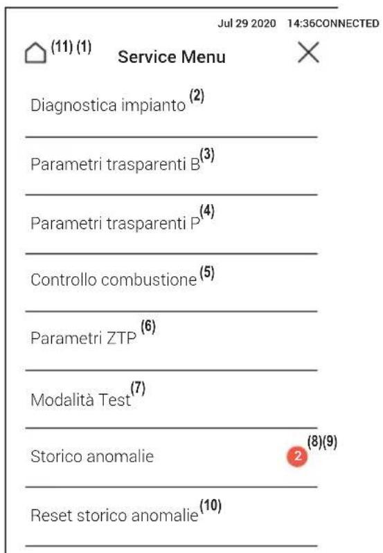
The values of the sensors and actuators in the boiler are available.
Note: To return to the Service Menu, touch the arrow at the top left of the screen
| Description Range | |
| Combustion | |
| Burner power 00%=Min., 100%=Max. | |
| Flame status 00÷255 | |
| Fan rpm 00÷120 | |
| Operating hours 00÷99 | |
| Fume Temperature 0÷125 °C | |
| Hydraulics | |
| Heating Flow 0÷125 °C | |
| Heating Return 0÷125 °C | |
| NTC DHW sensor (°C) 0÷125 °C | |
| DHW draw-off 00÷99 L/min | |
| Modulating pump speed 00÷100% | |
| System water pressure 00-9.9 bar with pressure transducer | |
| Environment | |
| External probe +70 ÷ -30°C | |
Transparent Parameters "B" menu

By selecting a parameter on the screen, the possible values will be shown. If the values shown do not match those indicated in the corresponding "Range" column, check that the parameter B01 is correctly set to RRT.
| Code | Description | Range | Default |
| B01 | Boiler type selection | RRP (INSTANTANEOUS COMBI)RRH (HEATING ONLY also with OPTIONAL HOT WATER STORAGE TANKRRT (COMBI HEATING ONLY)RRK (HEATING ONLY with HOT WATER STORAGE TANK) | RRT |
| B02 | Exchanger type | 1 ÷ 4 | BLUEHELIX MAXIMA 24C = 1BLUEHELIX MAXIMA 28C = 2BLUEHELIX MAXIMA 34C = 3 |
| B03 | Absolute Maximum Heating Power | 0 ÷ 100% (Do not modify the value) | BLUEHELIX MAXIMA 24C = 75%BLUEHELIX MAXIMA 28C = 85%BLUEHELIX MAXIMA 34C = 85% |
| B04 | System water pressure protection selection | Pressure switchPressure Transducer | Pressure transducer |
| B05 | NOT IMPLEMENTED | -- | |
| B06 | Variable input contact operation selection | Flow meter exclusionSystem thermostatSecond room therm.Warning/AlertSafety thermostat | Second room thermostat |
| B07 | Relay card LC32 selection | External gas valveAlarmSystem filling solenoid valveSolar 3-way valveSecond heating pumpAlarm2Burner litFrost protection active | System filling solenoid valve |
| B08 | Hours without DHW draw-off | 0 ÷ 24 hours (time for temporary deactivation of comfort mode without draw-off) | 24 |
| B09 | Fault 20 status selection | DeactivatedEnabled | Enabled |
| B10 | Not implemented -- -- | ||
| B11 | Flowmeter timing | Deactivated 1s ÷ 10s (seconds) | Deactivated |
| B12 | Modulation Delta 0 ÷ 30^/10 | 0^/10 | |
| B13 | Not implemented -- -- | ||
| B14 | Pump antiblock operation time | 0 ÷ 20 seconds 5 | |
| B15 | Flowmeter type selection | Flow. (450 imp/l)Flow. (700 imp/l)Flow (190 imp/l) | Flow (190 imp/l) |
| B16 | Fan frequency in standby mode | 0 ÷ 100% 0% | |
| B17 | NOT IMPLEMENTED -- | ||
| B18 | DHW mode activation flow rate | 0 ÷ 100L/min/10 25 | |
| B19 | DHW mode deactivation flow rate | 0 ÷ 100L/min/10 20 | |
| B20 | Flue material selection | 0 = Standard 1 = PVC 2 = CPVC | 0 |
| B21 | PVC flue maximum temperature | 60 ÷ 110^ 88^ | |
| B22 | CPVC flue maximum temperature | 60 ÷ 110^ 93^ | |
| B23 | Standard flue shutdown maximum temperature | 60 ÷ 110^ 100^ | |
| B24 | PVC flue shutdown maximum temperature | 60 ÷ 110^ 93^ | |
| B25 | CPVC flue shutdown maximum temperature | 60 ÷ 110^ 98^ | |
| B26 | Flow temperature limit in automatic calibration | 25^ ÷ 55^ 30^ | |
| B27 | Maximum temperature during calibration in DHW mode | 75^ ÷ 95^ 80^ | |
| B28 | Flowmeter sensitivity factor 0 | 60 (0 = disabled) 20 | |
| B29 | Restoring Factory Values | Set the value to 10 | - |
Notes:
- Parameters with more than one description vary their function and/or range in relation to the setting of the parameter given in brackets.
- Parameters with more than one description are reset to the default value if the parameter given in brackets is modified.
- The Maximum Heating Power parameter can also be modified in Test Mode.
To return to the service menu, touch the arrow at the top left of the screen.
Transparent Parameters "P" menu

By selecting a parameter on the screen, the possible values will be shown. If the values shown do not match those indicated in the corresponding "Range" column, check that the parameter B01 is correctly set to RRT.
| Code | Description | Range | Default |
| P30 | Heating ramp | 1 ÷ 20^/minute | 4^/minute |
| P31 | Virtual set point min. temperature | 0= Deactivated 1 ÷ 80^ | 0 |
| P32 | Heating standby time 0 ÷ 10 minutes 4 | ||
| P33 | Heating Post-Circulation 0 ÷ 25 minutes 15 | ||
| P34 | Pump operation | Fixed flow rate on callFixed continuous flow rateAdaptive flow rate on callAdaptive continuous flow rate | Adaptive flow rate on call |
| P35 | Modulating pump min. speed | 30 ÷ 100% 30% | |
| P36 | Modulating pump start speed | 90 ÷ 100% 90% | |
| P37 | Modulating pump max. speed | 90 ÷ 100% 100% | |
| P38 | Pump deactivation temperature during Post-Circulation | 0 ÷ 100°C 55°C | |
| P39 | Pump activation hysteresis temperature during Post-Circulation | 0 ÷ 100°C 25°C | |
| P40 | Heating user max. setpoint 20 | ÷ 90°C 80°C | |
| P41 | Max. output in heating 0 ÷ 100% 80% | ||
| P42 | Burner shutdown in DHW | FixedLinked to setpointSolar | Fixed |
| P43 | Comfort mode activation temperature | 0 ÷ 80°C 40°C | |
| P44 | Comfort mode deactivation hysteresis | 0 ÷ 20°C 20°C | |
| P45 | DHW standby time 30 ÷ 255 seconds 120 | ||
| P46 | DHW user max. setpoint 40 ÷ 70°C 55°C | ||
| P47 | DHW pump Post-Circulation | 0 ÷ 255 seconds | 30 |
| P48 | Max. output in DHW | 0 ÷ 100% | BLUEHELIX MAXIMA 24C = 86%BLUEHELIX MAXIMA 28C = 100%BLUEHELIX MAXIMA 34C = 100% |
| P49 | Not implemented | -- | -- |
| P50 | Not implemented | -- | -- |
| P51 | olar off temperature 0 ÷ 100°C 10°C | ||
| P52 | olar on temperature 0 ÷ 100°C 10°C | ||
| P53 | Solar standby time | 0 ÷ 255 seconds | 10 |
| P54 | Heating deltaT adjustment temperature | 0 ÷ 60°C 18°C | |
| P55 | Primary exchanger protection temperature | 0 ÷ 150°C 43°C | |
| P56 | System min. pressure value | 0 ÷ 8bar/10 | 4 bar/10 |
| P57 | System nominal pressure value | 5 ÷ 20bar/10 | 7 bar/10 |
| P58 | Exchanger protection intervention (b01=3) | 0 = No F431 ÷ 15 = 1 ÷ 15°C/second | 10°C/second |
| P59 | Heating hysteresis after ignition | 6 ÷ 30°C 10°C | |
| P60 | Timer for heating hysteresis after ignition | 60 ÷ 180 seconds 60 | |
| P61 | Pump deactivation with OpenTherm | 0 ÷ 1 | 0 |
| P62 | System filling mode | ManualAutomatic | Manual |
Notes:
-
Parameters with more than one description vary their function and/or range in relation to the setting of the parameter given in brackets.
-
Parameters with more than one description are reset to the default value if the parameter given in brackets is modified.
- The Maximum Heating Power parameter can also be modified in Test Mode.
To return to the service menu, simply touch the "arrow" icon in the top left corner of the screen.
Combustion Control Menu
ONLY QUALIFIED PERSONNEL CAN ACCESS THE MENU AND MODIFY THE RELEVANT PARAMETERS.
| Code | Description | Functional description | Range | Default |
| Sc01 Gas type selection | Allows the change of gas type. See “Gas conversion” on page 210 | NG/LPG NG | ||
| Sc02 Ignition gas calibration | Allows the amount of gas to be increased or decreased in the ignition phase in case of difficult starting. | -9 ÷ 20 0 | ||
| Sc03 Ignition power | Allows the fan speed to be increased or decreased in the ignition phase in case of difficult starting. | -16 ÷ 14 0 | ||
| Sc04 Flue length | Allows the boiler to be arranged according to the width and length of the flue used. To be used only with ∅50 or ∅60 flues. See fig. 19. | -2 ÷ 13 0 | ||
| Sc05 Minimum power calibration | Allows the minimum power to be increased, if necessary. | 0 ÷ 25 0 | ||
| Sc06 | Minimum gas valve calibration | Self-adaptive parameter. DO NOT MODIFY. | ||
| Sc07 Flame ionization signal Displays the actual ionization current signal. Read only | ||||
| Sc08 Current power ref. DHW | Displays the actual power referred to maximum power in DHW. | Read only | ||
| Sc09 | MAX ionization value | Displays the maximum ionization value reached. | Read only | |
| Sc10 Minimum ionization value during ignition | Displays the minimum ionization value reached during the ignition phase. | Read only | ||
| Sc11 | Ignition time | Displays the time from fan activation to ionization. | Read only | |
| Sc12* | Ionization reduction value (BASE) | NOT MODIFIABLE | Read only | 0 |
| Sc13** | Ionization reduction value (min.) | NOT MODIFIABLE | Read only | 0 |
| Sc14 | Internal error K1 | Displays the SCOT system error code. | Read only | |
| Sc15 100% CALIBRATION | Allows 100% Calibration (see “100% calibration” on page 211) in case of replacement of several components | 0 - 1 | 0 | |
ZTP (Sliding temperature) Parameters Menu
When the external probe is installed, the boiler adjustment system works with "Sliding Temperature". In this mode, the heating system temperature is regulated according to weather conditions, to ensure high comfort and energy efficiency throughout the year. In particular, as the outside temperature increases the system flow temperature decreases according to a specific "compensation curve".
With Sliding Temperature adjustment, the temperature set using the buttons [+] (detail 12 fig.1) and [-] (detail 14 fig.1) becomes the maximum system flow temperature. It is advisable to set a maximum value to allow system adjustment throughout its useful operating range.
The boiler must be adjusted at the time of installation by qualified personnel. However, the user can make any further adjustments necessary to optimize comfort levels.
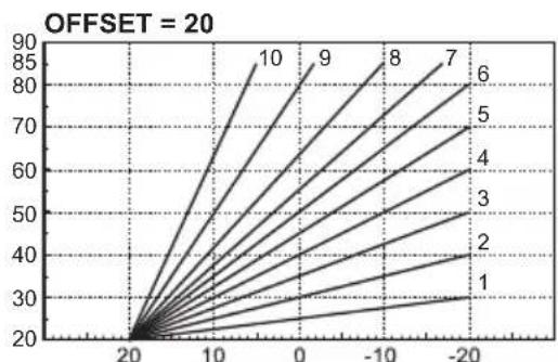
Compensation curve and curve offset
The settings of the compensation curves and relevant offset can be accessed via the service menu and touching the item [ZTP parameters]. Use fig. 25 as a reference for choosing the value of curve-type parameters and fig. 26 as a reference for choosing the value of offset-type parameters.
If the room temperature is lower than the required value, it is advisable to set a higher order curve and vice versa. Proceed by increasing or decreasing in steps of one and check the result in the room.
If the "Shutdown outside temperature" function is set to 0 it is disabled. If the value is set from 1 to 40^ it is active. Ignition occurs when the temperature of the outside probe is 2^ lower than the set temperature.

line
| Date | Value | | ---------- | ----- | | 20100-10-20 | 30 | | 20100-10-19 | 35 | | 20100-10-18 | 40 | | 20100-10-17 | 45 | | 20100-10-16 | 50 | | 20100-10-15 | 55 | | 20100-10-14 | 60 | | 20100-10-13 | 65 | | 20100-10-12 | 70 | | 20100-10-11 | 75 | | 20100-10-10 | 80 | | 20100-10-09 | 85 | | 20100-10-08 | 90 |fig. 25- Compensation curves

line
| x | y | |----|------| | 20 | 20 | | 10 | 30 | | 0 | 40 | | -10| 50 | | -20| 60 | | -30| 70 | | -40| 80 | | -50| 90 |
line
| x | y | | ---- | ---- | | 20 | 40 | | 10 | 85 | | 0 | 70 | | -10 | 60 | | -20 | 50 |fig. 26- Example of compensation parallel curve offset
Faults history
The card can store the last 10 faults. The fault code and a brief description are shown for each fault.
Faults History Reset
The list of faults recorded by the card can be cleared by touching the item [Faults history reset] and after confirming and entering the password "1234".
3.2 Commissioning
Before turning on the boiler
- Check the tightness of the gas system.
- Before filling the system, check the correct expansion vessel precharge.
- Fill the hydraulic system and make sure all air contained in the boiler and the system has been vented.
- Make sure there are no water leaks in the system, DHW circuits, connections or boiler.
- Make sure there are no flammable liquids or materials near the boiler.
- Check correct connection of the electrical system and efficiency of the grounding system.
- Make sure the gas valve is set for the gas to be used (see ***' - THROTTLE position and parameter setting' on page 210 *** - cap. 3.1 "Adjustments").
- Fill the trap (see cap. 2.7 "Condensate drain connection").

IF THE ABOVE INSTRUCTIONS ARE NOT OBSERVED THERE MAY BE RISK OF SUFFOCATION OR POISO-
NING DUE TO GAS OR FUMES ESCAPING; DANGER OF FIRE OR EXPLOSION. ALSO, THERE MAY BE A RISK OF ELECTRIC SHOCK OR FLOODING THE ROOM.
First boiler ignition
- Make sure there is no draw-off of hot water and room thermostat requests.
- Turn on the gas and check that the gas supply pressure ahead of the unit complies with the technical data table or in any case the tolerance provided for by the regulations.
- Power the boiler electrically, the FW and software version number appear on the display. Then the message "boiler start" appears with the timers indicating the progress of deaeration (see cap. 1.3 "Connection to the power supply, switching on and off" on page 193).
- At the end of the FH cycle, the display will show the winter mode screen, make the temperature adjustments: heating flow and DHW outlet (fig. 7 and fig. 6).
- Check if the flue parameter value (“Combustion Control Menu” on page 216) is suitable for the length of flue installed.
- In case of gas change (G20 - G30 - G31), check if the relevant parameter is suitable for the type of gas present in the supply system ("Combustion Control Menu" on page 216 and cap. 3.1 "Adjustments" on page 210).
- Set the boiler to DHW or heating mode (see cap. 1.3 "Connection to the power supply, switching on and off" on page 193).
- In heating mode, do a request: the current heating system temperature is shown on the display; when the flashing flame symbol appears it means that the burner is on and the system is calibrating. Wait for the end of calibration, indicated by the steady flame symbol.
- DHW mode with hot water draw-off present: the current DHW temperature is shown on the display; when the flashing flame symbol appears it means that the burner is on and the system is calibrating; wait for the end of the calibration which will be indicated with the steady flame symbol.
- Carry out the fuel check as described in par. "Checking the combustion values" on page 211.
3.3 Maintenance
IMPORTANT

ALL MAINTENANCE WORK AND REPLACEMENTS MUST BE CARRIED OUT BY SKILLED QUALIFIED PERSONNEL.
Before carrying out any operation inside the boiler, disconnect the power and close the gas cock upstream. Otherwise there may be a danger of explosion, electric shock, suffocation or poisoning.
Opening the front panel

Some internal components of the boiler can reach temperatures high enough to cause severe burns. Before carrying out any operation, wait for these components to cool or else wear suitable gloves.
To open the boiler casing, follow the sequence.


On this unit, the casing also acts as a sealed chamber. After any operation involving opening the boiler, carefully check the correct refitting of the front panel and its seal.
Periodical check
To ensure proper operation of the unit over time, have qualified personnel carry out a yearly inspection, providing for the following checks:
- The control and safety devices (gas valve, flow meter, sensors, etc.) must function correctly.
- The fume exhaust circuit must be perfectly efficient.
- The sealed chamber must be tight.
- The air-fume end piece and ducts must be free of obstructions and leaks
- The burner and exchanger must be clean and free of deposits. Use suitable brushes for cleaning. Never use chemical products.
- The electrode must be properly positioned and free of any deposits.
The electrode can be cleaned of incrustations only with a non-metallic brush, and must NOT be sanded.
- The gas and water systems must be tight.
- The water pressure in the system when cold must be approx. 1 bar; otherwise bring it to that value.
- The circulating pump must not be blocked.
- The expansion vessel must be filled.
- The gas flow and pressure must match that given in the respective tables.
- The condensate evacuation system must be efficient with no leakage or obstructions.
- The trap must be full of water.
- Check the quality of the water in the system.
- Check the condition of the insulation of the exchanger.
- Check the gas connection between the valve and Venturi.
- Replace the burner gasket if damaged.
- After the check, always control the combustion parameters (see "checking the combustion values").
Cleaning the exterior surfaces
So as not to alter the opacity of the painted plastic panel (ref. A fig. fig. 32) use mild degreasers that do not contain Mek or aggressive alcohols.
To clean the glass panel (ref. B fig. fig. 32), use isopropyl alcohol.
To clean the side panels (ref. C fig. fig. 32), use a mild detergent.
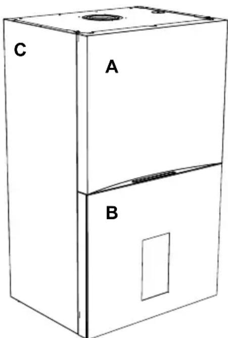
fig. 32
3.4 Troubleshooting
Diagnostics
During operation, the unit can generate two types of faults:
Type F They indicate the presence of a temporary fault. They are not indicated, but are recorded in the Service Menu faults history. If a type F fault is not resolved independently according to specific safety criteria, it becomes a type A fault.
Type A They indicate the presence of a blocking fault that requires user intervention to be resolved. They are indicated by lighting up of the red LEDs, the appearance of a specific window on the screen, and by the presence of a red dot on the main menu icon.
Unblocking the boiler with type A fault in progress
When a type A fault is present, the boiler can be unblocked in two ways:
1 - Touching [RESET] when a screen similar to that shown in fig. 33 appears.
2 - Touching the main menu icon and then [Boiler Reset] when a screen similar to that shown in fig. 34 (main menu icon with red dot) appears.
1
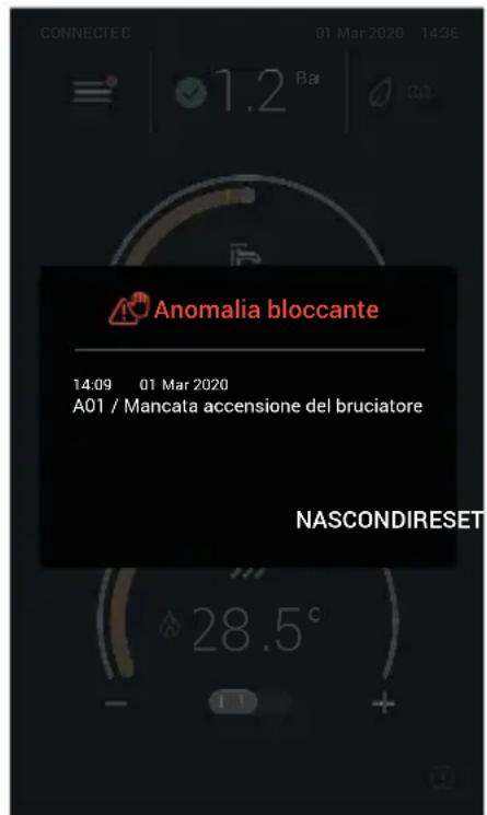
fig. 33
2
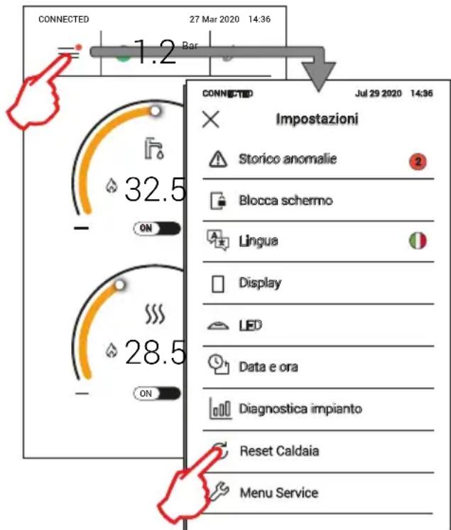
fig. 34
Table of faults
Table 8- List of faults
| Fault code Fault Possible cause Cure | |||
| A01 No burner ignition | No gas | Check the regular gas flow to the boiler and that the air has been eliminated from the pipes | |
| Ignition/detection electrode fault | Check the wiring of the electrode and that it is correctly positioned and free of any deposits; replace the electrode if necessary. | ||
| Faulty gas valve Check the gas valve and replace it if necessary | |||
| Insufficient gas supply pressure | Check the gas supply pressure | ||
| Trap blocked Check the trap and clean it if necessary | |||
| Air/fume ducts obstructed | Remove the obstruction from the flue, fume extraction ducts, air inlet and terminals. | ||
| A02 | Flame present signal with burner off | Electrode fault | Check the ionization electrode wiring |
| Check the condition of the electrode | |||
| Electrode to ground | |||
| Cable to ground | |||
| Check the trap and clean it if necessary | |||
| Card fault Check the card | |||
| A05 Fan fault | No 230V power supply | Check the 5-pin connector wiring | |
| Tachometric signal interrupted | |||
| Fan damaged Check the fan | |||
| A06 | No flame after the ignition phase | Ionization electrode fault Check the position of the ionization electrode and replace it if necessary | |
| Flame unstable Check the burner | |||
| air/fume ducts obstructed | Remove the obstruction from the flue, fume extraction ducts, air inlet and terminals | ||
| Trap blocked Check the trap and clean it if necessary | |||
| F03 F15 F18 A07 | High fume temperature | The fume probe detects an excessive temperature | Check the exchanger |
| Check the flue gas probe | |||
| Check the flue material parameter | |||
| F04 A08 | Overtemperature protection intervention | Heating sensor damaged | Check the correct positioning and operation of the heating sensor and replace it if necessary |
| No water circulation in the system | Check the circulating pump | ||
| Air in the system Vent the system | |||
| F16 A09 | Overtemperature protection intervention | Return sensor damaged | Check the correct positioning and operation of the return sensor and replace it if necessary |
| No water circulation in the system | Check the circulating pump | ||
| Air in the system Vent the system | |||
| F19 A10 | Flow sensor fault | Sensor damaged | Check the wiring or replace the sensorWiring shorted |
| Wiring disconnected | |||
| F22 A11 | Return sensor fault | Sensor damaged | Check the wiring or replace the sensorWiring shorted |
| Wiring disconnected | |||
| F12 DHW sensor fault | Sensor damaged | Check the wiring or replace the sensorWiring shorted | |
| Wiring disconnected | |||
| F17 A13 | Fume probe fault | Probe damaged | Check the wiring or replace the fume probeWiring shorted |
| Wiring disconnected | |||
| A14 | Fume extraction duct safety device intervention | Fault F03 generated 3 times in the last 24 hours | See fault F03 |
| A23 | Optimum water pressure not reached in foreseen time | Water supply trouble Check the connection to the water supply | |
| Loading valve blocked in closed position | Check the loading valve and valve control relay | ||
| A24 | Water pressure restored more than 3 times in 24h | Heating system leaks Check for leaks in the heating system | |
| DHW exchanger damaged Check the exchanger | |||
| A26 | Excessive water pressure more than 3 times in an hour | Pressure too high Expansion vessel empty or damaged | Partially drain the system |
| Expansion vessel empty or damaged | Check the expansion vessel | ||
| F34 Supply voltage under 170V Electric mains trouble Check the electrical system | |||
| F20F37 | System water pressure too low | Pressure too low Fill the system | |
| Water pressure switch/pressure transducer not connected or damaged | Check the water pressure switch/pressure transducer | ||
| F39 External probe fault | Probe damaged or wiring shorted | Check the wiring or replace the sensor | |
| Probe disconnected after activating the sliding temperature | Reconnect the external probe or disable the sliding temperature | ||
| F41 | Activation of maximum DELTA T protection | Heating sensor damaged | Check the correct positioning and operation of the heating sensor |
| Return sensor damaged | Check the correct positioning and operation of the return sensor | ||
| No water circulation in the system | Check the circulating pump | ||
| Air in the system Vent the system | |||
| F21F40 | System water pressure too high | Pressure too high Partially drain the system | |
| Filling valve blocked in open position | Check the filling valve and valve control relay | ||
| Expansion vessel empty or damaged | Check the expansion vessel | ||
| F36A42 | Sensor control protection activation | Return and/or flow sensor damaged or disconnected | Check the correct positioning and operation of the return and/or flow sensor |
| Return sensor damaged or disconnected | Check the correct positioning and operation of the return sensor | ||
| F43 | Exchanger protection intervention. | No system H2O circulation | Check the circulating pump |
| Air in the system Vent the system | |||
| F47 Water pressure sensor error | Water pressure sensor disconnected | Check the water pressure sensor wiring | |
| Water pressure sensor damaged | Check the water pressure sensor | ||
| F51 | Low water pressure with parameter b06 = 3 | Pressure too low Fill the system | |
| Secondary water pressure switch disconnected or damaged | Check the water pressure switch/pressure transducer | ||
| Incorrect parameter Check the correct parameter setting | |||
| F50 - F53 | Limit thermostat fault with parameter b06 = 1 or 4 | No/poor water circulation in the system | Check the circulating pump |
| Air in the system Vent the system | |||
| Incorrect parameter Check the correct parameter setting | |||
| F57 - A56 | Calibration fault | Incorrect parameters | Check parameters and carry out a 100% calibration |
| Electrode damaged or not correctly positioned. | Check the position of the electrode, replace it if necessary. After replacement, repeat the 100% calibration | ||
| Recirculation of fumes inside the boiler | Check the tightness of the flue pipe and the seal of gaskets | ||
| Calibration procedure not completed | Poor primary circuit circulation or poor dissipation during calibration | Reset the fault. Turn on the hot water faucet and wait for the flame to stop flashing (about 2 minutes) | |
| F58 - A61 Controller fault Controller internal error | Check the ground connection.Check the electrode.If necessary replace the control unit. | ||
| A54 - A55 - A63 Controller fault Controller internal error | Try disconnecting the power supply to the boiler for 10 seconds and replace the controller if necessary | ||
| F67 BCC Service key connected Load the parameters | |||
| F65 - A68 BCC Service key error | Error loading BCC Service key file | Repeat the loading procedure within 5 minutes from the boiler power supply and replace the BCC Service key if necessary | |
| A62 | No communication between controller and gas valve | Controller not connected | Connect the controller to the valveCheck the wiring |
| Valve damaged Replace the valve | |||
| A64 | Maximum number of consecutive Resets exceeded | Maximum number of consecutive Resets exceeded | Turn off the power to the boiler for 60 seconds and then reinstate the boiler |
| F66 | Firmware not loaded successfully | Reload the firmware or replace the card | |
4. Technical data and characteristics
4.1 Dimensions and connections

fig. 35- Front view

fig. 36- Side view

fig. 37- Top view

fig. 38- Bottom view
7 Gas inlet - ∅ 3/4"
8 DHW outlet - ∅ 1/2"
9 Cold water inlet - ∅ 1/2"
10 System flow - ∅ 3/4"
11 System return - ∅ 3/4"
A6 Condensate discharge connection
Metal template (code 046049X0) and wall holes

Paper template and wall holes
The boiler comes with a paper template for the wall holes.
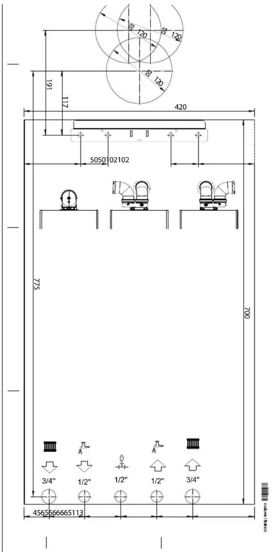
fig. 41- Paper template
4.2 General view

fig. 42- General view
14 Safety valve
16 Fan
32 Heating circulating pump
34 Heating temperature sensor
36 Automatic air vent
42 DHW temperature probe
44 Gas valve
56 Expansion vessel
81 Ionization/ignition electrode
95 Diverter valve
136 Flowmeter
145 Water gauge
186 Return sensor
191 Fume temperature sensor
193 Trap
194 DHW exchanger
196 Condensate tray
240 System filling solenoid valve
294 Pressure sensor
350 Fan/Burner assembly
4.3 Hydraulic circuit
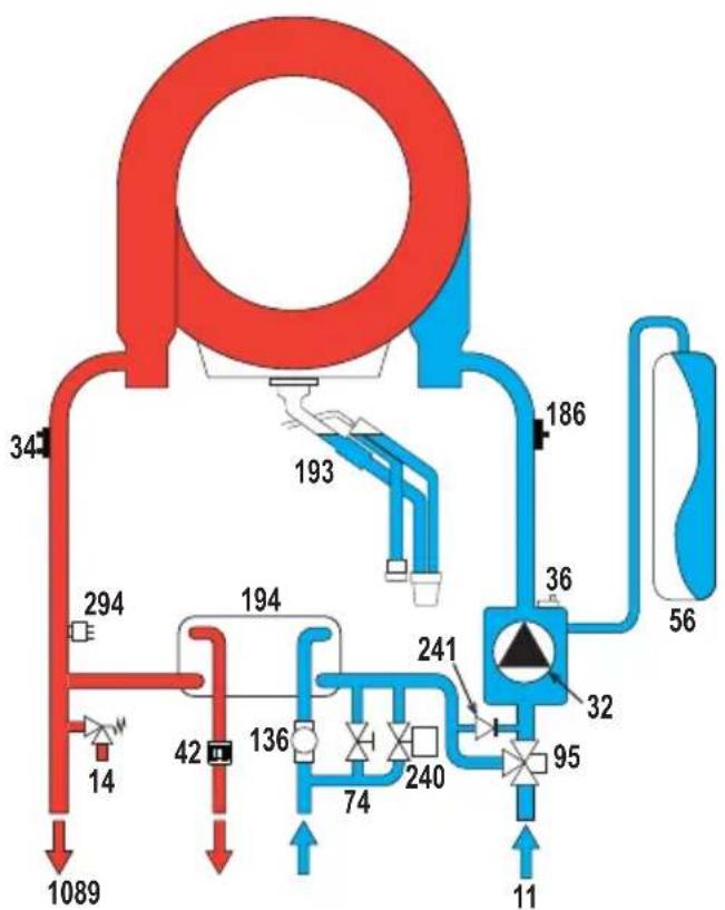
flowchart
graph TD
    A["1089"] --> B["34"]
    B --> C["193"]
    C --> D["186"]
    D --> E["56"]
    E --> F["32"]
    F --> G["95"]
    G --> H["11"]
    H --> I["74"]
    I --> J["240"]
    J --> K["241"]
    K --> L["136"]
    L --> M["42"]
    M --> N["14"]
    N --> O["294"]
fig. 43- Hydraulic circuit
8 Domestic hot water outlet
9 Cold water inlet
10 System flow
11 System return
14 Safety valve
32 Heating circulating pump
34 Heating temperature sensor
36 Automatic air vent
241 Automatic bypass (inside the pump unit)
294 Pressure sensor
4.4 Technical data table
| 0TSB2MWA | BLUEHELIX MAXIMA 24C |
| 0TSB4MWA | BLUEHELIX MAXIMA 28C |
| 0TSB7MWA | BLUEHELIX MAXIMA 34C |
| COUNTRIES OF DESTINATION IT ES RO PL | |||||
| GAS CATEGORY II2HM3+ (IT) II2H3+ (ES) II2H3B/P (RO) II2ELwLs3B/P (PL) | |||||
| PRODUCT IDENTIFICATION CODES | 0TSB2MWA | 0TSB4MWA | 0TSB7MWA | ||
| Max. heating capacity | kW | 20,4 | 24,5 | 30,6 | Qn |
| Min. heating capacity | kW | 2,9 | 2,9 | 2,9 | Qn |
| Max. heat output in heating (80/60°C) | kW | 20,0 | 24,0 | 30,0 | Pn |
| Min. heat output in heating (80/60°C) | kW | 2,8 | 2,8 | 2,8 | Pn |
| Max. heat output in heating (50/30°C) | kW | 21,6 | 26,0 | 32,5 | Pn |
| Min. heat output in heating (50/30°C) | kW | 3,1 | 3,1 | 3,1 | Pn |
| Max. heating capacity in DHW | kW | 25,0 | 28,5 | 34,7 | Qnw |
| Min. heating capacity in DHW | kW | 2,9 | 2,9 | 2,9 | Qnw |
| Max. heat output in DHW | kW | 24,5 | 28,0 | 34,0 | |
| Min. heat output in DHW | kW | 2,8 | 2,8 | 2,8 | |
| Efficiency Pmax (80-60°C) | % | 98,1 | 98,1 | 97,9 | |
| Efficiency Pmin (80-60°C) | % | 98,0 | 98,0 | 98,0 | |
| Efficiency Pmax (50-30°C) | % | 106,1 | 106,1 | 106,1 | |
| Efficiency Pmin (50-30°C) | % | 107,5 | 107,5 | 107,5 | |
| Efficiency 30% | % | 109,7 | 109,7 | 109,5 | |
| Gas supply pressure G20 | mbar | 20,0 | 20,0 | 20,0 | |
| Max. gas flow G20 | m3/h | 2,65 | 3,02 | 3,67 | |
| Min. gas flow G20 | m3/h | 0,31 | 0,31 | 0,31 | |
| CO2 - G20 | % | 9 ±0,8 | |||
| Gas supply pressure G31 | mbar | 37,0 | 37,0 | 37,0 | |
| Max. gas flow G31 | kg/h | 1,94 | 2,21 | 2,70 | |
| Min. gas flow G31 | kg/h | 0,23 | 0,23 | 0,23 | |
| CO2 - G31 | % | 10 ±0,8 | |||
| NOx emissions class | - | 6 (< 56 mg/kWh) | NOx | ||
| Max. working pressure in heating | bar | 3,0 | 3,0 | 3,0 | PMS |
| Min. working pressure in heating | bar | 0,8 | 0,8 | 0,8 | |
| Heating adjustment max. temperature | °C | 95 | 95 | 95 | tmax |
| Heating water content | liters | 2,9 | 2,9 | 4,3 | |
| Heating expansion vessel capacity | liters | 8 | 8 | 10 | |
| Heating expansion vessel precharge pressure | bar | 0,8 | 0,8 | 0,8 | |
| Max. working pressure in DHW | bar | 9,0 | 9,0 | 9,0 | PMW |
| Min. working pressure in DHW | bar | 0,3 | 0,3 | 0,3 | |
| DHW flow rate Dt 25°C | l/min | 14,0 | 16,1 | 19,5 | |
| DHW flow rate Dt 30°C | l/min | 11,7 | 13,4 | 16,2 | D |
| DHW water content | litri | 0,3 | 0,3 | 0,4 | H2O |
| Protection rating | IP | IPX4D | |||
| Power supply voltage | V/Hz | 230V~50HZ | |||
| Electrical power input | W | 73,0 | 82,0 | 99,0 | W |
| Empty weight | kg | 28,0 | 28,0 | 32,0 | |
| Type of unit C10-C11-C13-C23-C33-C43-C53-C63-C83-C93-B23-B33 | |||||
| C10-C11 flues installation pressure Pa | 77 80 | 79 | |||
ErP product fiche
MODEL: BLUEHELIX MAXIMA 24C - (0TSB2MWA)
| Trademark: FERROLI | |||
| Condensing boiler: YES | |||
| Low-temperature boiler (**): YES | |||
| B1 Boiler: NO | |||
| Combination heater: YES | |||
| Cogeneration space heater: NO | |||
| Item | Symbol | Unit | Value |
| Seasonal space heating energy efficiency class (from A+++ to D) | A | ||
| Rated heat output | Pn | kW | 20 |
| Seasonal space heating energy efficiency | _s | % | 93 |
| Useful heat output | |||
| Useful heat output at rated heat output and high-temperature regime (*) | P4 | kW | 20,0 |
| Useful heat output at 30% of rated heat output and low-temperature regime (**) | P1 | kW | 3,8 |
| Useful efficiency | |||
| Useful efficiency at rated heat output and high-temperature regime (*) | _4 | % | 88,3 |
| Useful efficiency at 30% of rated heat output and low-temperature regime (**) | _1 | % | 98,8 |
| Auxiliary electricity consumption | |||
| At full load | elmax | kW | 0,022 |
| At part load | elmin | kW | 0,010 |
| In standby mode | PSB | kW | 0,003 |
| Other items | |||
| Standby heat loss | Pstby | kW | 0,042 |
| Ignition burner power consumption | Pign | kW | 0,000 |
| Annual energy consumption | QHE | GJ | 38 |
| Sound power level | LWA | dB | 44 |
| Emissions of nitrogen oxides | NOx | mg/kWh | 39 |
| For combination heaters | |||
| Declared load profile | XL | ||
| Water heating energy efficiency class (from A+ to F) | A | ||
| Daily electricity consumption | Qelec | kWh | 0,154 |
| Annual electricity consumption | AEC | kWh | 33 |
| Water heating energy efficiency | _wh | % | 87 |
| Daily fuel consumption | Qfuel | kWh | 20,330 |
| Annual fuel consumption | AFC | GJ | 17 |
(*) High-temperature regime means 60°C return temperature at heater inlet and 80°C feed temperature at heater outlet.
(**) Low temperature means for condensing boilers 30°C, for low-temperature boilers 37°C and for other heaters 50°C return temperature (at heater inlet).
ErP product fiche
MODEL: BLUEHELIX MAXIMA 28C - (0TSB4MWA)
| Trademark: FERROLI | |||
| Condensing boiler: YES | |||
| Low-temperature boiler (**): YES | |||
| B1 Boiler: NO | |||
| Combination heater: YES | |||
| Cogeneration space heater: NO | |||
| Item | Symbol | Unit | Value |
| Seasonal space heating energy efficiency class (from A+++ to D) | A | ||
| Rated heat output | Pn | kW | 24 |
| Seasonal space heating energy efficiency | _s | % | 94 |
| Useful heat output | |||
| Useful heat output at rated heat output and high-temperature regime (*) | P4 | kW | 24,0 |
| Useful heat output at 30% of rated heat output and low-temperature regime (**) | P1 | kW | 4,5 |
| Useful efficiency | |||
| Useful efficiency at rated heat output and high-temperature regime (*) | _4 | % | 88,3 |
| Useful efficiency at 30% of rated heat output and low-temperature regime (**) | _1 | % | 98,8 |
| Auxiliary electricity consumption | |||
| At full load | elmax | kW | 0,028 |
| At part load | elmin | kW | 0,011 |
| In standby mode | PSB | kW | 0,003 |
| Other items | |||
| Standby heat loss | Pstby | kW | 0,042 |
| Ignition burner power consumption | Pign | kW | 0,000 |
| Annual energy consumption | QHE | GJ | 44 |
| Sound power level | LWA | dB | 45 |
| Emissions of nitrogen oxides | NOx | mg/kWh | 39 |
| For combination heaters | |||
| Declared load profile | XL | ||
| Water heating energy efficiency class (from A+ to F) | A | ||
| Daily electricity consumption | Qelec | kWh | 0,148 |
| Annual electricity consumption | AEC | kWh | 34 |
| Water heating energy efficiency | _wh | % | 87 |
| Daily fuel consumption | Qfuel | kWh | 20,229 |
| Annual fuel consumption | AFC | GJ | 17 |
(*) High-temperature regime means 60°C return temperature at heater inlet and 80°C feed temperature at heater outlet.
(**) Low temperature means for condensing boilers 30°C, for low-temperature boilers 37°C and for other heaters 50°C return temperature (at heater inlet).
ErP product fiche
MODEL: BLUEHELIX MAXIMA 34C - (0TSB7MWA)
| Trademark: FERROLI | |||
| Condensing boiler: YES | |||
| Low-temperature boiler (**): YES | |||
| B1 Boiler: NO | |||
| Combination heater: YES | |||
| Cogeneration space heater: NO | |||
| Item | Symbol | Unit | Value |
| Seasonal space heating energy efficiency class (from A+++ to D) | A | ||
| Rated heat output | Pn | kW | 30 |
| Seasonal space heating energy efficiency | _s | % | 94 |
| Useful heat output | |||
| Useful heat output at rated heat output and high-temperature regime (*) | P4 | kW | 30,0 |
| Useful heat output at 30% of rated heat output and low-temperature regime (**) | P1 | kW | 5,5 |
| Useful efficiency | |||
| Useful efficiency at rated heat output and high-temperature regime (*) | _4 | % | 88,2 |
| Useful efficiency at 30% of rated heat output and low-temperature regime (**) | _1 | % | 98,6 |
| Auxiliary electricity consumption | |||
| At full load | elmax | kW | 0,036 |
| At part load | elmin | kW | 0,009 |
| In standby mode | PSB | kW | 0,003 |
| Other items | |||
| Standby heat loss | Pstby | kW | 0,046 |
| Ignition burner power consumption | Pign | kW | 0,000 |
| Annual energy consumption | QHE | GJ | 55 |
| Sound power level | LWA | dB | 47 |
| Emissions of nitrogen oxides | NOx | mg/kWh | 37 |
| For combination heaters | |||
| Declared load profile | XXL | ||
| Water heating energy efficiency class (from A+ to F) | A | ||
| Daily electricity consumption | Qelec | kWh | 0,167 |
| Annual electricity consumption | AEC | kWh | 37 |
| Water heating energy efficiency | _wh | % | 85 |
| Daily fuel consumption | Qfuel | kWh | 25,582 |
| Annual fuel consumption | AFC | GJ | 22 |
(*) High-temperature regime means 60°C return temperature at heater inlet and 80°C feed temperature at heater outlet.
(**) Low temperature means for condensing boilers 30°C, for low-temperature boilers 37°C and for other heaters 50°C return temperature (at heater inlet).
4.5 Diagrams
Residual head available for system
BLUEHELIX MAXIMA 24C and BLUEHELIX MAXIMA 28C

line
| Q (m3/h) | H(mCA) | | -------- | ------ | | 00.10 | 6.7 | | 0.20 | 6.7 | | 0.30 | 6.7 | | 0.40 | 6.7 | | 0.50 | 6.7 | | 0.60 | 6.7 | | 0.70 | 6.7 | | 0.80 | 6.7 | | 0.91 | 6.7 | | 1.12 | 6.5 | | 1.21 | 6.2 | | 1.31 | 5.8 | | 1.41 | 5.3 | | 1.51 | 4.8 | | 1.61 | 4.3 | | 1.71 | 3.8 | | 1.81 | 3.3 | | 1.91 | 2.8 | | 2.01 | 2.3 | | 2.11 | 1.8 | | 2.21 | 1.3 | | 2.31 | 0.8 | | 2.41 | 0.3 | | 2.51 | 0.0 |fig. 44- Residual head available for system
BLUEHELIX MAXIMA 34C
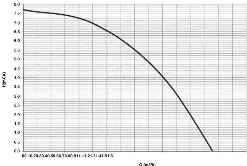
line
| Q (m3/h) | H(mCA) | | -------- | ------ | | 00.10 | 7.8 | | 02.20 | 7.6 | | 04.30 | 7.5 | | 05.40 | 7.4 | | 06.50 | 7.3 | | 07.60 | 7.2 | | 08.70 | 7.1 | | 09.80 | 7.0 | | 11.00 | 6.8 | | 12.20 | 6.5 | | 13.40 | 6.2 | | 14.60 | 5.8 | | 15.80 | 5.3 | | 17.00 | 4.8 | | 18.20 | 4.2 | | 19.40 | 3.5 | | 20.60 | 2.8 | | 21.80 | 2.0 | | 23.00 | 1.2 | | 24.20 | 0.5 | | 25.40 | 0.0 |fig. 45- Residual head available for system
4.6 Wiring diagram (fig. 46)
16 Fan
32 Heating circulating pump
34 Heating temperature sensor
Attention: Remove the jumper on the terminal block before connecting the room thermostat or the remote timercontrol.
To connect multiple zones of the plumbing system controlled by thermostats with voltage-free contact and to use the timer control as a function of remote boiler controls, connect the voltage-free contacts of the zones to terminals 1-2 and the timer control to terminals 5-6.
ALL CONNECTIONS TO THE TERMINAL BLOCK MUST BE WITH VOLTAGE-FREE CONTACTS (NOT 230V).

FERROLI S.p.A.
Via Ritonda 78/a
37047 San Bonifacio - Verona - ITALY
www.ferroli.com



- CE
- Verificarea valorilor de combustie
- Operating instructions .... 192
- Installation....198
- Service and maintenance....210
- Technical data and characteristics 225
- Operating instructions
- Introduction
- Control panel
- Connection to the power supply, switching on and off
- Boiler not electrically powered
- Boiler electrically powered
- Activation of boiler operating modes
- Adjustments
- Enable/Disable the heating function
- DHW temperature adjustment
- Heating temperature adjustment
- Room temperature adjustment with timer control
- ECO mode
- Restoring system hydraulic pressure
- "Pressure control" screen
- Description of "Pressure control" screen
- Legend fig. 8
- System hydraulic pressure manual reset
- System semiautomatic pressure restoration (P62 = 0)
- System automatic pressure restoration (P62 = 1)
- System draining
- Installation
- General Instructions
- Place of installation
- Plumbing connections
- Important
- Antifreeze system, antifreeze fluids, additives and inhibitors
- System water characteristics
- Recommended chemical conditioners:
- Frost protection kit for outdoor installation (optional - 013022X0)
- Gas connection
- Electrical connections
- Room thermostat
- Accessing the electrical terminal block
- Terminal block auxiliary input configuration
- Fume ducts
- Installation type C10
- Use of ∅50 and ∅60 flexible pipe (for ducting only)
- ONLY FOR THE ITALIAN MARKET
- Backflow preventer valve
- Condensate drain connection
- ATTENTION: THE UNIT MUST NEVER BE OPERATED WITH THE TRAP EMPTY!
- OTHERWISE THERE IS A DANGER OF SUFFOCATION DUE TO THE EMISSION OF COMBUSTION FUMES.
- THE CONDENSATE DRAIN MUST BE CONNECTED TO THE DRAINAGE SYSTEM IN SUCH A WAY THAT THE LIQUID CONTAINED CANNOT FREEZE.
- Service and maintenance
- Adjustments
- Gas conversion
- MAKE SURE THE FRONT CASING IS CLOSED AND THE INTAKE/FUME EXHAUST DUCTS ARE COMPLETELY ASSEMBLED
- Checking the combustion values
- 100% calibration
- 100% calibration, automatic
- 100% calibration, manual
- Calibration procedure.
- Loading parameters with "BCC KEY"
- TEST mode activation
- Heating power adjustment
- Service menu
- Transparent Parameters "B" menu
- Notes:
- Transparent Parameters "P" menu
- Combustion Control Menu
- ZTP (Sliding temperature) Parameters Menu
- Compensation curve and curve offset
- Faults history
- Faults History Reset
- Commissioning
- Before turning on the boiler
- IF THE ABOVE INSTRUCTIONS ARE NOT OBSERVED THERE MAY BE RISK OF SUFFOCATION OR POISO-
- NING DUE TO GAS OR FUMES ESCAPING; DANGER OF FIRE OR EXPLOSION. ALSO, THERE MAY BE A RISK OF ELECTRIC SHOCK OR FLOODING THE ROOM.
- First boiler ignition
- Maintenance
- ALL MAINTENANCE WORK AND REPLACEMENTS MUST BE CARRIED OUT BY SKILLED QUALIFIED PERSONNEL.
- Opening the front panel
- Periodical check
- Cleaning the exterior surfaces
- Troubleshooting
- Diagnostics
- Unblocking the boiler with type A fault in progress
- Table of faults
- Technical data and characteristics
- Dimensions and connections
- Metal template (code 046049X0) and wall holes
- Paper template and wall holes
- General view
- Hydraulic circuit
- ErP product fiche
- Diagrams
- Wiring diagram (fig. 46)
Brand : FERROLI
Model : Bluehelix Maxima
Category : Boiler