
VM148 - Thermostat VELLEMAN - Free user manual and instructions
Find the device manual for free VM148 VELLEMAN in PDF.


| Product type | Programmable digital thermostat |
| Brand | Velleman |
| Model | VM148 |
| Temperature range | -18 to +60 °C (0 to 146 °F) |
| Display resolution | ±0.5 °C / ±2 °F |
| Accuracy | ±2 °C (adjustable up to ±0.5 °C by calibration) |
| Refresh rate | 1 second |
| Display | Bright red LED |
| Relay contact | NO (normally open), 3 A max. 230 V~ |
| Power supply | 9 - 12 V DC |
| Power consumption | < 70 mA |
| Sensor | External, 20 cm cable (board-to-wire) |
| Weight | 50 g |
| Main functions | Heating/cooling regulation, adjustable hysteresis, adjustable target temperature, calibration, underflow/overflow/sensor fault indication |
| Operating modes | Heating (Temp A > Temp B), Cooling (Temp A < Temp B) |
| Hysteresis | Minimum difference of 0.5 °C between Temp A and Temp B |
| Warranty | 2 years (parts and labor), upon presentation of receipt |
| Maintenance and cleaning | Clean with a dry, soft cloth. Do not use liquids. |
| Safety instructions | Installation by qualified personnel; avoid moisture; do not exceed electrical limits; not suitable for life-support systems. |
| Repairability | Repair by qualified personnel only; spare parts available from manufacturer |
Frequently Asked Questions - VM148 VELLEMAN
User questions about VM148 VELLEMAN
0 question about this device. Answer the ones you know or ask your own.
Ask a new question about this device
Download the instructions for your Thermostat in PDF format for free! Find your manual VM148 - VELLEMAN and take your electronic device back in hand. On this page are published all the documents necessary for the use of your device. VM148 by VELLEMAN.
USER MANUAL VM148 VELLEMAN
PANEL THERMOSTAT MODULE

natural_image
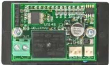
Close-up of a green printed circuit board with buttons and components (no readable text or symbols)VM148
Belgium [Head office] +32(0)9 384 36 11
France +33(0)3 20 15 86 15
Netherlands +31(0)76 514 7563
USA +1(817)284-7785
Spain +32(0)9 384 36 11
Panel thermostat module 4
Thermostaat module 7
Module thermostat 10
Thermostatmodul 13
Módulo termostato 16
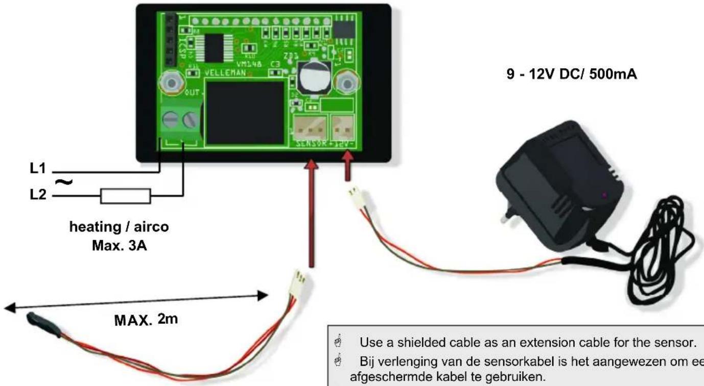
CONNECTION - AANSLUITING - CONNEXION - ANSCHLUSS - CONEXIÓN
☑ general purpose panel mount thermostat
☑ usable for heating or cooling purposes, (central heating, airco, incubator,...)
☑ separate output-ON and output-OFF setting (hysteresis)
☑ direct manual temperature adjustment
☑ bright red LED read-out
☑ calibrate option
☑ under- and overflow indication
Specifications:
• temperature range:
^ °C: -18°C \~ + 60°C
°F: 0°F \~ +146°F
• temperature resolution: ± 0.5°C or ± 2°F
• accuracy: +/- 2°C, fine tune till +/- 0,5°C
• readout update interval: 1 second
• relay contact: NO - 3A (max. 230V)
• power supply: 9 - 12V DC
• power consumption: < 70mA
- weight: 50g
Factory settings: Temp°A = 22°C Temp°B = 20°C Temp correction = 0° Temp display = °C
WARRANTY
This product is guaranteed against defects in components and construction from the moment it is purchased and for a period of TWO YEAR starting from the date of sale. This guarantee is only valid if the unit is submitted together with the original purchase invoice. VELLEMAN components Ltd limits its responsibility to the reparation of defects or, as VELLEMAN components Ltd deems necessary, to the replacement or reparation of defective components. Costs and risks connected to the transport, removal or placement of the product, or any other costs directly or indirectly connected to the repair, will not be reimbursed by VELLEMAN components Ltd. VELLEMAN components Ltd will not be held responsible for any damages caused by the malfunctioning of a unit.
SAFETY INSTRUCTIONS
■ All repairs should be executed by qualified technicians.
■ Avoid the installation of the module in locations with standing or running water or excessive humidity. Indoor use only!
■ Handle the module gently and carefully. Dropping it can damage the circuit board.
■ Never exceed the protection limit values indicated in the specifications.
■ As safety requirement vary, please check with your local authorities.
■ Facilitate the operation of the device by familiarising yourself with its adjustments and indications.
■ Velleman modules are not suitable for use or as part of life support systems, or systems that might create hazardous situations of kind.
Introduction:
Thank you for choosing Velleman. This multifunctional digital thermostat module allows you to control and monitor the room temperature.
Modules needed:
Apart from the VM148 module, you will be needing a 12VDC power supply. Use an external contactor with currents higher than 3A.
Possibilities:
- The module allows you to maintain the room temperature between 2 programmed limits. Example: The room temperature must not drop below 20^ . Once the heating is activated, the room temperature must reach 22^ before being deactivated.
• Control of the air conditioning system.
• Temperature monitoring in e.g. a housing or greenhouse, of a liquid...).
General definitions:
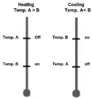
Hysteresis: Temperature difference between temp° A and temp °B (min. 0.5°C). Temp°A will automatically rise with 0.5°C if the two temperature settings have been programmed identically.
Heating mode: Activation of the heating when the measured temperature ≤ programmed temperature B until the measured temperature > programmed temperature A. Heating mode is activated when temp°A > temp°B.
Cooling mode: Activation of the air conditioning system when the measured temperature > programmed temperature B until the ambient temperature drops below programmed temperature A. Cooling mode is activated when temp°A < temp°B.
A red dot is displayed in the right corner below when the relay, and consequently the connected device, is activated.
Temperature display: The actual temperature and the settings can be displayed in ° Celsius and ° Fahrenheit.
2. SET-UP
The actual measured temperature is displayed at power-on or in normal mode.
Press to access the set-up menu.
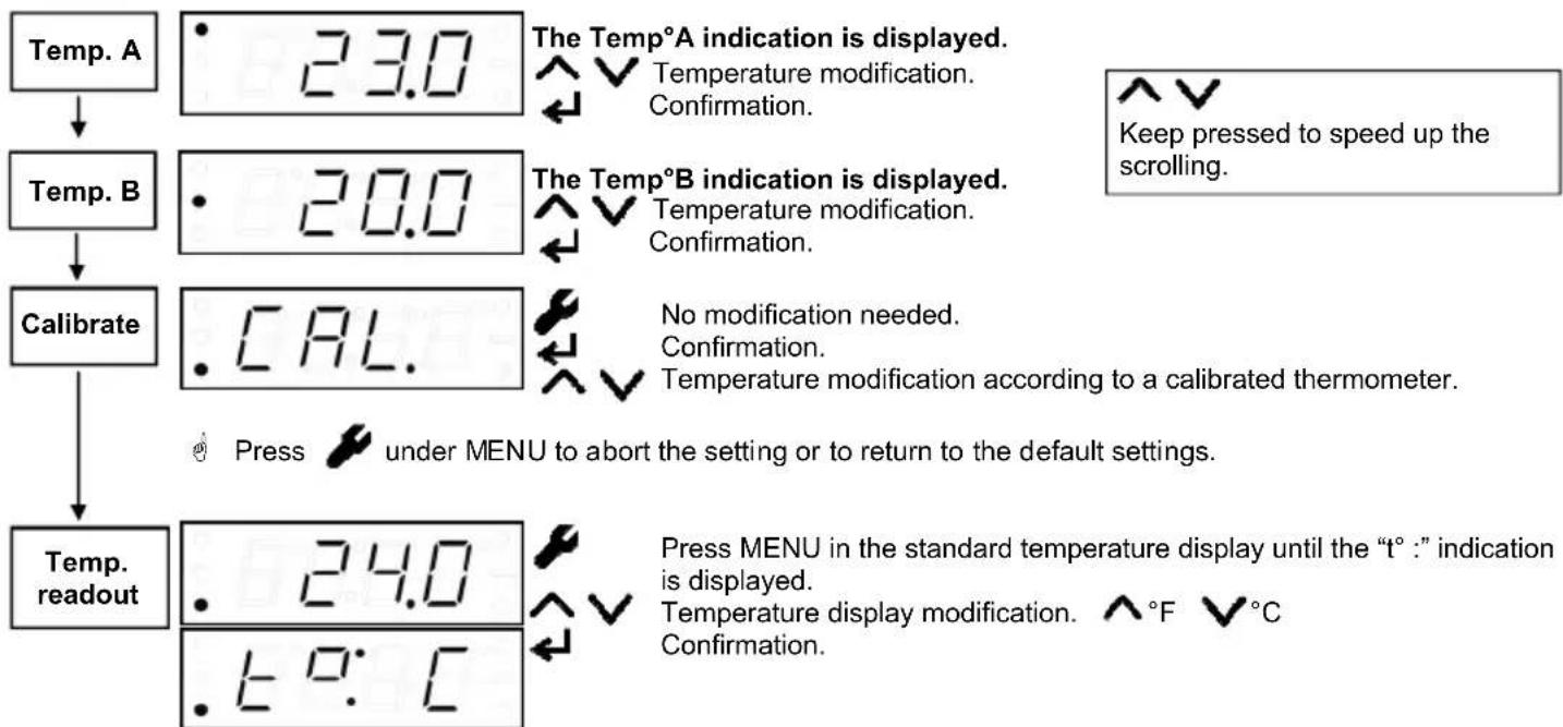
flowchart
graph TD
    A["Temp. A"] --> B["23.0"]
    B --> C["Temp. B"]
    C --> D["20.0"]
    D --> E["Calibrate"]
    E --> F["CAL"]
    F --> G["Press under MENU to abort the setting or to return to the default settings."]
    G --> H["Temp. readout"]
    H --> I["24.0"]
    I --> J["Press MENU in the standard temperature display until the "t°:" indication is displayed."]
    I --> K["Temperature display modification. ^°F ✓°C Confirmation."]
    style A fill:#f9f,stroke:#333
    style B fill:#ccf,stroke:#333
    style C fill:#ccf,stroke:#333
    style D fill:#ccf,stroke:#333
    style E fill:#ccf,stroke:#333
    style F fill:#ccf,stroke:#333
    style H fill:#ccf,stroke:#333
    style I fill:#ccf,stroke:#333
3. ERROR INDICATIONS
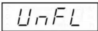
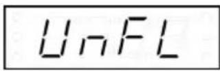
UnFL – Underflow error: The measured temperature is lower than the minimum measurable temperature (min. temp° = -18°C of 0°F).
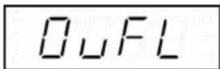
OvFL – Overflow error: The measured temperature is higher than the maximum measurable temperature (max. temp° = +60°C of 146°F).
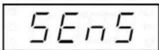
SEnS – Sensor error: Sensor problem or faulty connection.
Press ENTER to display the operation mode of the temperature controller.
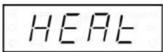
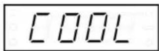
Heating mode: temp° A > temp° B
Cooling mode: temp° A < temp° B
5. TEMPERATURE MODIFICATION
This handy function allows you to modify the temperature directly without reprogramming the max. and min. values (temp° A and temp° B). the limit values will automatically shift with the temperature modification.
Shortly press UP ▲ or DOWN ▼ in the temperature display to display the average target temperature.

Repeatedly press UP ▲ or DOWN ▼ to rise or lower the target temperature. Example: Set the target temperature to 25°C; temp° A and temp° B will automatically be modified to 26°C and 24°C.
6. FACTORY SETTINGS
Remove the power supply to the module. Hold ENTER pressed and re-establish the power supply to the module. DEF (default) will be displayed. Release the ENTER button. The display will show the firmware version code.
3. INDICATIONS D'ERREUR

Modifications and typographical errors reserved - © Velleman Components nv - HVM148G - 2009 - ED1
Brand : VELLEMAN
Model : VM148
Category : Thermostat