
PR4500 - Receiver AKG - Free user manual and instructions
Find the device manual for free PR4500 AKG in PDF.


| Product type | Wireless handheld receiver |
| Brand | AKG |
| Model | PR4500 |
| Carrier frequency range | 500.1 – 821.5 MHz (depending on model) |
| Modulation | FM |
| Audio bandwidth | 35 – 15,000 Hz |
| Signal-to-noise ratio (line output) | 100 dB(A) typ. |
| Headphone output | Stereo 3.5 mm jack, nominal output level 387 mV (10 mW into 150 ohms), max power 100 mW/channel |
| Line output (LINE OUT) | Mono 2.5 mm jack, nominal level 316 mV rms (-10 dBV), impedance 600 ohms |
| Power supply | 2 AA batteries or BP4000 rechargeable battery |
| Battery life | 6 to 12 hours |
| Dimensions (W x H x D) | 70 x 90 x 25 mm |
| Net weight with batteries | 165 g |
| Operating temperature | -10°C to +50°C |
| Main features | Backlit LCD display, manual/automatic frequency selection, interference frequency search (Field Scan), adjustable squelch (-100 to -82 dBm), acoustic protection limiter, LOCK/SETUP mode |
| Maintenance and cleaning | Soft cloth slightly dampened with water |
| Safety | Avoid liquids, do not open the device, respect maximum sound levels, use only recommended batteries/rechargeable batteries |
| Spare parts and repairability | BP4000 rechargeable battery, CU4000 charger, AA batteries; repair only by authorized personnel |
| Included accessories | Belt clip, adapter shoe, 2.5 mm to XLR jack cable, 2.5 mm to 3.5 mm jack cable |
Frequently Asked Questions - PR4500 AKG
User questions about PR4500 AKG
0 question about this device. Answer the ones you know or ask your own.
Ask a new question about this device
Download the instructions for your Receiver in PDF format for free! Find your manual PR4500 - AKG and take your electronic device back in hand. On this page are published all the documents necessary for the use of your device. PR4500 by AKG.
USER MANUAL PR4500 AKG
Please read the manual before using the equipment!
MODE D'EMPLOI p. 34
flowchart
graph LR
    A["1"] --> B["Signal transceiver with 4G/5G ports"]
    B --> C["Battery charging"]
    C --> D["Disassembly of battery"]
    D --> E["Final device with cable"]
Getting Started Quickly....19
Symbols and Characters....20
1 Safety and Environment....21
Safety 21
High Volume 21
Environment 22
FCC Statement....22
2 Description 23
Introduction 23
Packing List....23
Optional Accessories 23
PR4500 Portable Receiver 23
Controls....23
Display 24
3 Setting Up 25
Setting Up the Receiver....25
Inserting Batteries....25
Inserting the PA4500 Powering Adapter....25
Powering Up....25
LOCK Mode....26
SETUP Mode 26
Locking/Unlocking 26
Setting the Audio Input Level....26
Setting the Headphone Volume 26
Frequency Selection....27
Selecting the Country Preset....27
Manual Adjustment in MHz 27
Manual Selection from a Preset....27
Automatic Selection for a Single-channel System 28
Automatic Selection for a Multichannel System....28
Powering Down....28
Mounting the Receiver....28
Belt Clip 28
Hot-shoe Adapter....28
Velcro Fastener....29
Connecting to ENG Equipment....29
4 Advanced Functions....30
Finding Interference Frequencies....30
Setting the Squelch Threshold 30
Hearing Protection Limiter....30
Info 31
5 Cleaning....31
6 Troubleshooting....32
7 Specifications....33
8 Appendix....97
Receiver Menus 97
Basic Functions (Figs. A1 to A5....98
Advanced Functions (Figs. A6 to A9)....101
Figs. 3 to 8....Foldout Pages
flowchart
graph LR
    A["1"] --> B["Signal Transmission"]
    B --> C["Battery Release"]
    C --> D["Data Transfer"]
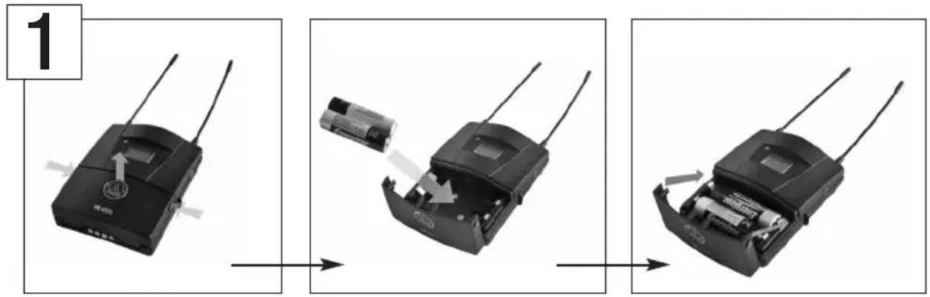
Insert the supplied batteries into the receiver.
flowchart
graph TD
    A["Device"] --> B["840850 MHz"]
    B --> C["BATBAT"]
    C --> D["AT7AD1"]
    D --> E["Figs. A4, A5"]
    F["CH"] --> G["Output"]
    H["Input"] --> I["Output"]
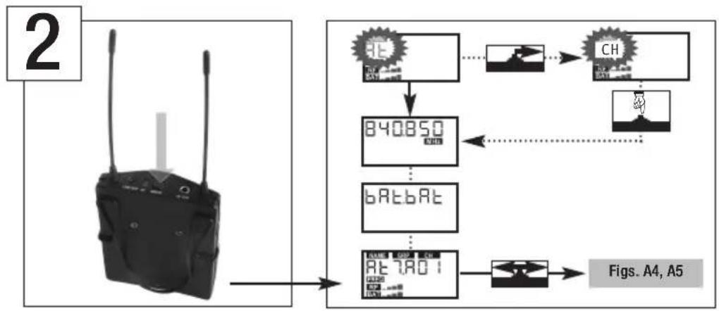
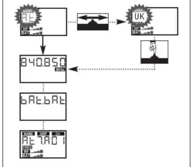
Switch power to the receiver on and select the code for the country where you are going to operate your receiver (refer to "Selecting the Country Preset" on page 27 and fig. A2 in the Appendix).
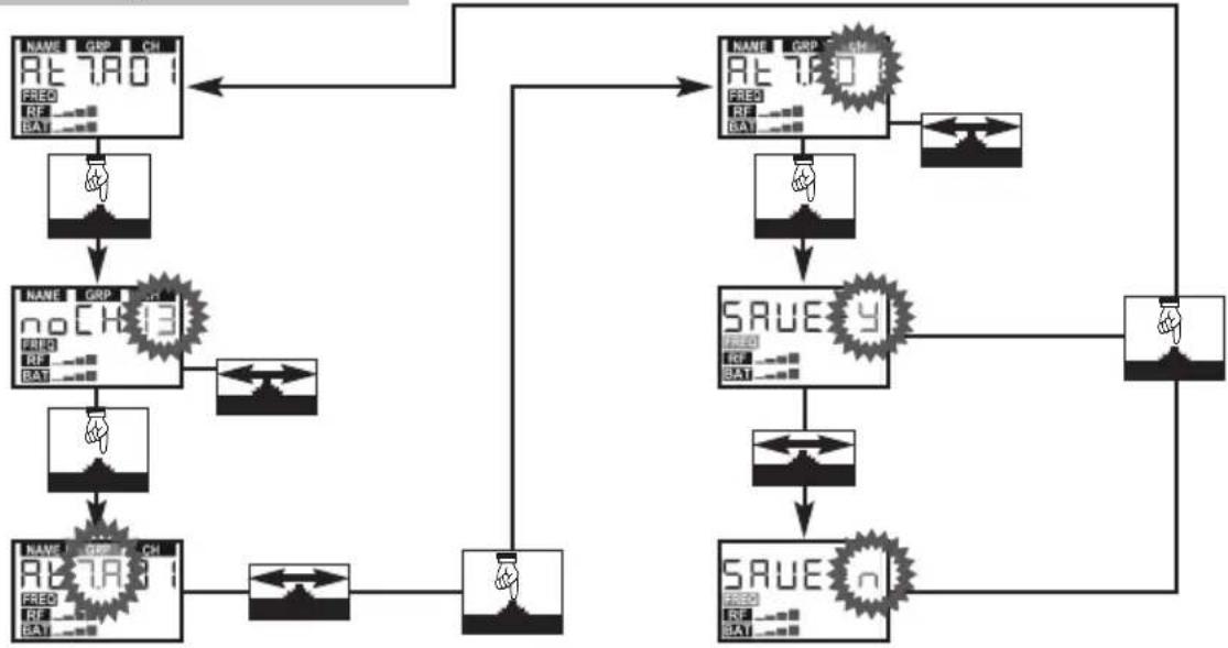
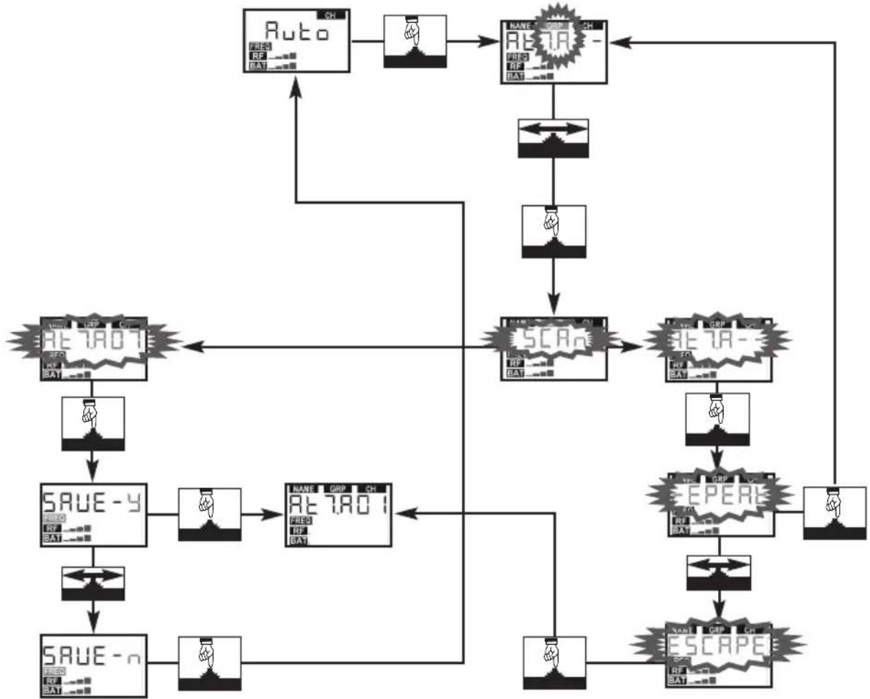
2 Select a clean frequency on the receiver manually (fig. A3) or using the automatic search function (fig. A4).
Tune the transmitter to the same frequency you selected on the receiver (refer to transmitter manual).
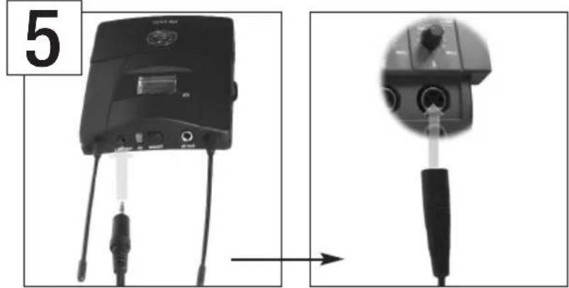
Use one of the supplied connecting cables to connect the LINE OUT jack on the receiver to the camera or recording device. See page 13.
6 Connect your headphones to the receiver.
7 Switch power to the receiver on and set the headphones volume to the desired level. (Refer to page 26, "Setting the Headphones Volume".)
Symbols Used in the Manual
The following symbols are used in the menu diagrams Figs. A1 through A9 on pages 97 to 103:
| Setup Control Symbol Action | |
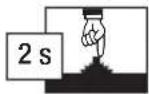 | Long push(appropx. 2 secs.) |
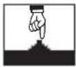 | Short push |
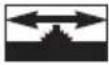 | Turn all the way up or down |
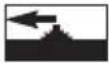 | Turn all the way down |
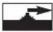 | Turn all the way up |
Display Characters
| Flashing character | |||||||||||
| 7 | H | R |  | ||||||||
| - | - | 8 | 8 | I | S | 5 | |||||
| . | 9 | 9 | J | T | E | ||||||
| 0 | 0 | A | A | K | U | U | |||||
| 1 | B | b | L | V | u | ||||||
| 2 | 2 | C | c | M | W | W | |||||
| 3 | 3 | D | d | N | X | x | |||||
| 4 | 4 | E | E | O | Y | y | |||||
| 5 | 5 | F | F | P | Z | z | |||||
| 6 | 6 | G | G | Q | |||||||
- Do not spill any liquids on the equipment and do not drop any objects through the ventilation slots in the equipment.
- The equipment may be used in dry rooms only.
- The equipment may be opened, serviced, and repaired by authorized personnel only. The equipment contains no user-serviceable parts.
- Operate the equipment with the included AA size dry batteries or the dry or rechargeable batteries recommended in this manual only.
- If any solid object or liquid penetrates into the equipment, shut down the sound system immediately. Remove the batteries from the equipment immediately and have the equipment checked by AKG service personnel.
- Do not place the equipment near heat sources such as radiators, heating ducts, or amplifiers, etc. and do not expose it to direct sunlight, excessive dust, moisture, rain, mechanical vibrations, or shock.
- Clean the equipment with a moistened (not wet) cloth only. Be sure to disconnect the power supply cable from the power outlet before cleaning the equipment! Never use caustic or scouring cleaners or cleaning agents containing alcohol or solvents since these may damage the enamel and plastic parts.
- Use the equipment for the applications described in this manual only. AKG cannot accept any liability for damages resulting from improper handling or misuse.
- In some countries, you may need a permit for operating your equipment. Be sure to contact the respective authority of the country where you are going to operate your equipment.
- Any modifications made to the equipment without the express consent of AKG may lead to violations of telecommunications legislation voicing the operating permit.

High Volume
- Listening over headphones at excessive sound pressure levels, particularly over extended periods of time, may damage your hearing! Therefore, always set the volume as low as possible.

Table 1 is based on research in occupational medicine conducted in Germany and lists maximum exposure times for high volume levels before hearing damage occurs. Please note that local legislation where you will use your equipment may differ from the values in Table
1. Basically, you can double the maximum exposure time without damaging your ears by reducing the sound pressure level by 3 dB.
| Sound pressure Maximum exposure | |
| 85 dB(A) 8 hours | |
| 88 dB(A) 4 hours | |
| 91 dB(A) 2 hours | |
| 94 dB(A) 1 hour | |
| 97 dB(A) 30 minutes | |
| 100 dB(A) 15 minutes | |
| 120 dB(A) Threshold of pain | |
Table 1
To protect your ears from damage, follow a few tips:
- Set the volume just high enough to hear properly.
- If you hear ringing or whistling sounds in your ears, fail to hear high notes (even momentarily), or hear less clearly for a while after a concert, you have been exposed to excessive sound pressure levels for too long. Consult an audiologist and use lower volume levels.
1 Safety and Environment
- Have your ears checked by an audiologist on a regular basis.
- To avoid infections, wipe the ear molds with a skin compatible antiseptic before and after use. Stop using the earbuds if they are causing great discomfort or infection.
- When scrapping the equipment, separate the case, circuit boards, and cables, and dispose of all components in accordance with local waste disposal rules.
- The packaging of the equipment is recyclable. Dispose of the packaging in an appropriate container provided by the local waste collection/recycling entity and observe all local legislation relating to waste disposal and recycling. Environment
FCC Statement
This equipment has been tested and found to comply with the limits for a Class B digital device, pursuant to Part15 of the FCC Rules. These limits are designed to provide reasonable protection against harmful interference in a residential installation. This equipment generates, uses, and can radiate radio frequency energy and, if not installed and used in accordance with the instructions, may cause harmful interference to radio communications. However, there is no guarantee that interference will not occur in a particular installation. If this equipment does cause harmful interference to radio or television reception, which can be determined by turning the equipment off and on, the user is encouraged to try to correct the interference by one or more of the following measures:
- Reorient or relocate the receiving antenna.
- Increase the separation between the equipment and the receiver.
- Connect the equipment into an outlet on a circuit different from that to which the receiver is connected.
- Consult the dealer or an experienced radio/TV technician for help.
Shielded cables and I/O cords must be used for this equipment to comply with the relevant FCC regulations.
Changes or modifications not expressly approved in writing by AKG Acoustics may void the user's authority to operate this equipment.
This device complies with Part 15 of the FCC Rules. Operation is subject to the following two conditions: (1) this device may not cause harmful interference, and (2) this device must accept any interference received, including interference that may cause undesired operation.
2 Description
Thank you for purchasing an AKG product. This Manual contains important instructions for setting up and operating your equipment. Please take a few minutes to read the instructions below, particularly section 1 "Safety and Environment", carefully before operating the equipment. Please keep the Manual for future reference. Have fun and impress your audience!
Introduction
• 1 PR4500 bodypack receiver
- 1 belt clip
• 2 AA size dry batteries
- 1 hot-shoe adapter
• 1 connecting cable (2.5 mm jack to XLR)
- 1 connecting cable (2.5 mm jack to 1/8" jack)
- Check that the packaging contains all of the items listed above. Should any of these items be missing, please contact your AKG dealer.
Packing List
- For optional accessories, refer to the current AKG catalog or folder, or visit www.akg.com. Your dealer will be glad to help.
Optional Accessories
The PR4500 bodypack receiver has been designed specifically for use with WMS4500 Series transmitters from AKG. You can connect any headphone with a 1/8"jack plug to the headphones jack on the receiver.
PR4500
Bodypack Receiver
To power the receiver you can use either the two supplied dry batteries or the optional BP4000 battery pack from AKG.
The hot-shoe adapter with mounting plate allows you to attach the receiver to a camera or camera stand in seven different positions.
You can easily mount the receiver securely on equipment with no hot shoe or stand-mount-ing thread using commercial velcro fastener (not included).
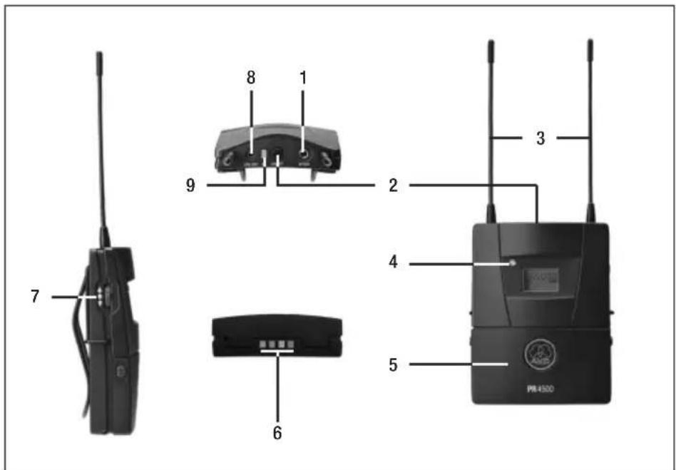
Controls
Fig. 1: Controls and outputs.
1 HP OUT: Adjustable 1/8" TRS output jack for headphones.
Refer to fig. 1.
2 ON/OFF button.
3 Permanently attached flexible antennas
2 Description
4 Status LED
5 Battery compartment accepting two AA size dry batteries (included) or an optional BP4000 battery pack.
6 Charging contacts for charging the BP4000 battery pack on the optional CU4000 charger.
7 Setup control: Sets the various parameters of the receiver.
8 LINE OUT: 2.5-mm line-level output jack. The LINE output provides a fixed-level audio signal.
9 AF: This bi-color LED indicates the input level to the audio section:
Green: > -40 dB (signal present) Red: > -3 dB (the input is almost overloaded)
Display
Fig. 2: Display.
Refer to fig. 2.
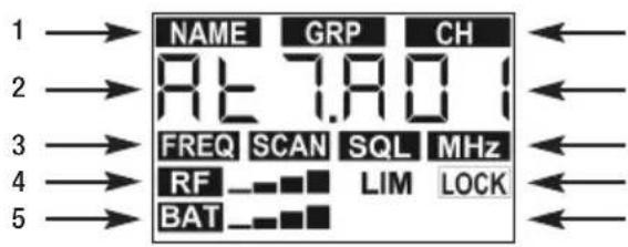
The display indicates all operating parameters of the receiver:
1 Menus for Preset (country code), Frequency Group, Channel.
2 Alphanumeric display.
3 Menus for preset frequency, frequency in MHz, field scan, squelch.
4 RF level meter, limiter indicator, LOCK mode label.
5 Battery capacity and powering mode.
- Prior to every soundcheck, verify that the transmitter and receiver are tuned to the same frequency.

- The adjustment procedures for all receiver parameters are diagrammatically shown in figs. A1 to A9 on pages 122 through 136.

Setting Up the Receiver
Inserting Batteries
Refer to fig. 3.
-
Open the battery cover (1).
-
Insert the two supplied batteries (2) into the battery compartment, aligning the batteries with the polarity symbols inside the battery compartment. If you insert the batteries the wrong way, the receiver will not be powered.
-
Close the battery cover (1).
- As an alternative to the supplied batteries, you can use the optional BP4000 battery pack from AKG to power the receiver. Refer to fig. 4.

- Never use standard rechargeable batteries! These may damage the receiver if the charging contacts are shorted and will provide no meaningful remaining-battery-life indication. AKG will accept no liability for any damage resulting from the use of standard rechargeable batteries.

Powering Up
- Press the ON/OFF button.
- Status LED is lit green: power to receiver is on, radio link operating.
- Status LED is lit red: power to receiver is off or batteries will be dead in less than 60 minutes.
- Status LED remains dark: no batteries or dead batteries inside the battery compartment.
- When powering up for the first time, the first thing you need to do is select the appropriate Preset for the country where you are going to use your PR PRO. Read on in the section on "Selecting the Country Preset".
- When powering up again later, the receiver will automatically come on in LOCK mode. The display will indicate
- the selected frequency in MHz for about 2 seconds,
- "-Accu-" for about 2 seconds (if a BP4000 is in the battery compartment),
- and finally, the selected frequency (refer to fig. A1 in the Appendix).

3 Setting Up
| LOCK Mode | In order to ensure maximum reliability, the receiver setup functions are electronically locked so it is not possible to change any settings unintentionally. The "LOCK" label is lit on the display.You can scroll through the following status screens:- Preset (comes up only if a Preset has been saved): Carrier frequency shown as a Channel number within a Frequency Group.- Frequency: Carrier frequency in MHz. (This screen is always available, even if no Preset has been saved.)- Headphone volume: current headphone output level setting.- Battery: Percent battery capacity. (This screen is only available if you are using a BP4000 battery pack.) |
| SETUP Mode | In SETUP mode, the electronic lock is disabled so you can adjust all receiver parameters. The "LOCK" label is not shown. |
| Locking/UnlockingSetting theAudio Input Level | To toggle between LOCK and SETUP modes, hold down the Setup control for about 2 seconds. |
 Note Note | The receiver has no gain control. Therefore, in order to get optimum radio transmission, you need to set the audio level on the transmitter, e.g., an HT4500 or PT4500.To match the audio signal level to the input sensitivity of the camera, you need to set the audio input gain on the camera. Check the camera manual for related instructions. |
| Check the transmitter and microphone manual(s): | 1. Switch power to the transmitter and receiver ON.2. Set the audio gain on the transmitter to a low value.3. Talk into the microphone as loudly as possible or aim the microphone at the sound source to be picked up.4. Increase the transmitter gain CAUTIOUSLY to the highest notch where the AF LED will still remain green, without flashing red. This setting prevents unwanted noise and gives good results. |
 Note Note | To get optimum results, set the audio gain as high as possible in order to avoid unwanted noise.If, however, you set the audio gain too high, you risk getting unpleasant-sounding distortion. Therefore, make sure to set the audio gain just high enough for the AF LED on the receiver to indicate no overload - i.e., to remain green without flashing red. |
| Setting theHeadphone Volume | In SETUP mode.Call up the "Headphone Volume" menu.The display indicates the current volume setting. Press the Setup control once. The displayed setting starts flashing.Use the Setup control to select the desired volume level.The displayed value indicates the relative volume level in dB. The maximum setting being 0 dB, lower levels are indicated by negative numbers. Between 0 dB and -48 dB, settings are shown in 1-dB increments, lower settings in larger increments. The lowest selectable level is -65 dB.Press the Setup control once. The displayed setting is stored and stops flashing. |

CAUTION
- The selected volume setting remains stored in memory upon powering down and will be restored automatically upon powering up again.
- The volume setting affects the headphone output level only and does not affect the LINE output.

Note
The WMS 4500 Series is exceptionally frequency agile. You can either set the receiving frequency manually in MHz or select it automatically from pre-programmed frequencies for even quicker and easier system setup. All frequencies have been optimized by AKG for simultaneous operation of several radio channels and are subdivided into Presets for specific countries or regions, Groups, and Channels.
Frequency Selection
- You can select the receiving frequency in one of the following ways:
- Manual adjustment in MHz.
- Manual selection from pre-programmed frequencies.
- Automatic selection of a clean frequency from a Group.
-
Automatic selection of a clean frequency from a Group containing a selectable number of clean frequencies for applications where several wireless microphones will be used.
-
When you switch power to the receiver on for the first time, the "NAME" label and the name of the first programmed Preset will be flashing.
Selecting the Country Preset
Refer to fig. A2 in the Appendix.
- To select the appropriate Preset for a specific country later on (e.g., when traveling), hold down the setup control and press the ON/OFF button.

Note
- Turn the setup control up or down to select the desired Preset (country code).
-
Press the setup control briefly. The receiver will start up and automatically indicate the first Channel ("CH") of the first Frequency Group in memory. The receiver is in SETUP mode so you can easily select a different frequency.
-
In SETUP mode, turn the setup control up or down as many times as needed to call up the frequency screen.
- Press the setup control briefly.
- The MHz value starts flashing: To increase the value, turn the setup control briefly up. To decrease the value, turn the setup control briefly down.
- Press the setup control briefly.
-
The kHz value starts flashing: To increase the value, turn the setup control briefly up. To decrease the value, turn the setup control briefly down.
-
In SETUP mode, turn the setup control up or down as many times as needed to call up the Preset screen.
- Press the setup control briefly.
- "NO CH" flashing: Turn the setup control up or down to select the number of channels you need (e.g., "8" for an 8-channel system). This makes sure that the system will always be able to find enough clean frequencies within the same Frequency Group.
- Press the setup control briefly.
- Turn the setup control up or down to select ta Group.
- Press the setup control briefly.
- Turn the setup control up or down to select ta Channel.
Manual Selection in MHz
Refer to fig. A3 in the Appendix.
Manual Selection from a Preset
Refer to fig. A4.1 in the Appendix.
3 Setting Up
Automatic Selection for a Single-channel System
Refer to fig. A4.2 in the Appendix.
- In SETUP mode, turn the setup control up or down as many times as needed to call up the "AUTO" and "CH" labels on the display.
- Press the setup control briefly.
- Turn the setup control up or down to select ta Group.
- The receiver will automatically tune to the first clean frequency it finds.
- If the receiver finds no clean frequency, you can select "REPEAT" to try again.
Automatic Selection for a Multichannel System
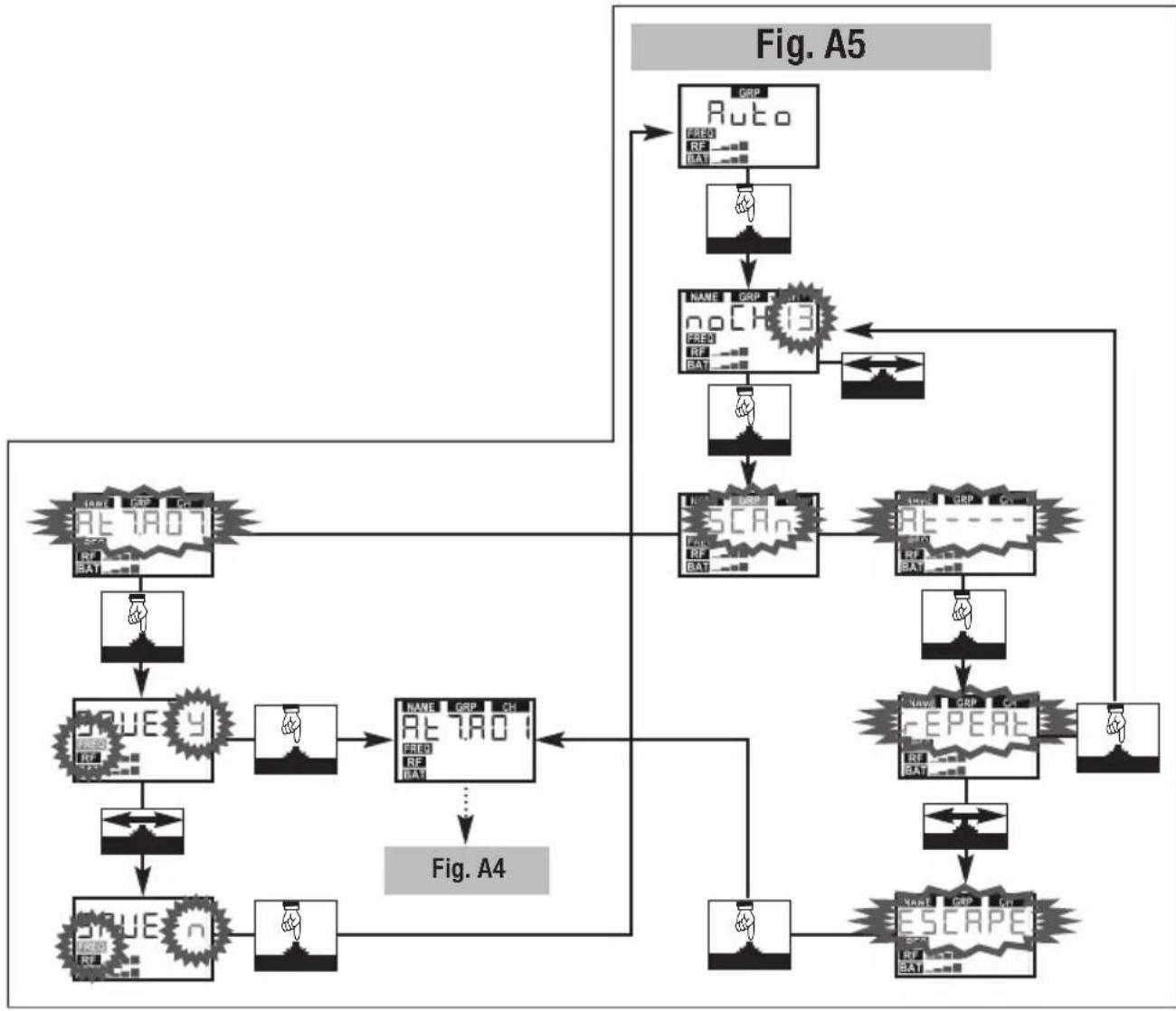
Refer to fig. A5 in the Appendix.
- In SETUP mode, turn the setup control up or down as many times as needed to call up the "AUTO" and "GRP" labels on the display.
- "NO CH" starts flashing: Turn the setup control up or down to select the number of Channels you need (e.g., "4" for a 4-channel system). This makes sure that the system will always be able to find enough clean frequencies within the same Frequency Group.
- The receiver will automatically search a Group with the selected number of clean frequencies within the selected Preset and tune to the first clean frequency it finds.
- If the receiver finds no clean frequency, you can select "REPEAT" to try again.

Note
If the receiver finds no clean Group/frequency:
- Slowly increase the squelch threshold. Refer to page XX, "Setting the Squelch Threshold".
Make sure never to set the squelch threshold any higher than absolutely necessary. The higher the squelch threshold (-100 dB = min., -86sdB = max.), the shorter the usable range between transmitter and receiver.
Powering Down
To make sure the receiver cannot be switched off unintentionally, it can be switched off in SETUP mode only. (In SETUP mode, the display does not show the "LOCK" label)
-
If the receiver is in LOCK mode (the display showing the "LOCK" label), switch the receiver to SETUP mode first: hold down the Setup control for about 2 seconds. The "LOCK" label disappears.
-
Hold down the ON/OFF button for about 2 seconds.
Mounting the Receiver
The belt clip and the hot-shoe adapter with mounting plate provide many ways to attach the receiver to the user's clothes, a camera, or an external recording device.
Belt Clip
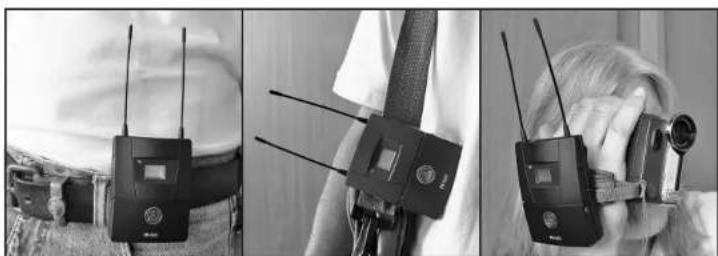
Refer to fig. 5.
- The belt clip provides a simple way to fix the receiver on a trouser belt, a shoulder strap, or hand strap of a video camera.
Hot-shoe Adapter
The supplied hot-shoe adapter consists of a mounting plate fixed to an adapter matching a standard camera hot shoe. The mounting plate provides several threaded holes for fixing the receiver in seven different positions.
The female thread on the adapter matches the treaded stud on standard camera tripods. A fixing screw on the adapter secures the adapter on the hot shoe.
Refer to fig. 6.
- Remove the belt clip (1) from the receiver.
- Place the hot-shoe adapter (2) on the receiver rear panel.
- Use the belt clip (1) to secure the receiver on the hot-shoe adapter (2).
- Slide the hot-shoe adapter carrying the receiver into the camera's hot shoe.
- Tighten the fixing screw (3) on the hot-shoe adapter to secure the receiver on the camera.
- If you wish to mount the receiver on the camera in a different position (e.g., further up front or to the rear):
- Unscrew the fixing screw (4) and remove the adapter from the mounting plate (6).
- Use the fixing screw (4) to fix the adapter (5) in the desired position on the mounting plate (6).
- Remove the belt clip (1) from the receiver.
- Place the hot-shoe adapter (2) on the receiver rear panel.
- Use the belt clip (1) to secure the receiver on the hot-shoe adapter (2).
- Slide the hot-shoe adapter carrying the receiver into the camera's hot shoe.
- Tighten the fixing screw (3) on the hot-shoe adapter to secure the receiver on the camera.
To mount the receiver on smooth surfaces, we recommend using commercial auto-adhesive Velcro fastener.
- Peel the protective film off a length of velcro tape.
- Press the tape firmly against the desired spot on the backing surface.
- Peel the protective film off another length of velcro tape and press the tape firmly against the receiver rear panel.
-
Press the receiver against the tape on the backing surface, slowly moving the receiver back and forth to engage the hooks and loops on the tapes.
-
Use the supplied cable with a 2.5-mm TS jack plug (1) on one end and XLR connector (2) on the other end to connect the LINE OUT jack on the receiver to the desired line-level input on your camera or recording device.
To connect the receiver to a camera with a 1/8" input jack, use the connecting cable with a 2.5 mm TS jack and 1/8" TS jack that is also included with the PR4500.2.
If you are going to use headphones, connect them to the HP OUT jack on the receiver.
- Set the headphone volume as desired.
Alternative positions:
Refer to fig. 7.
Velcro Fastener
Connecting
to ENG Equipment
Refer to fig. 8.
- To prevent hum interference, do not connect any cable longer than 10 feet (3 m) to the LINE OUT jack!
- The volume setting affects the headphone output level only and does not affect the LINE output.
- The LINE OUT level is not adjustable. To get optimum results, set the input gain on your transmitter and camera as recommended in the respective instruction manuals.

Note
In addition to the basic functions described in section 3 above, the receiver provides a series of advanced functions.
Finding Interference Frequencies
("Field Scan" function)
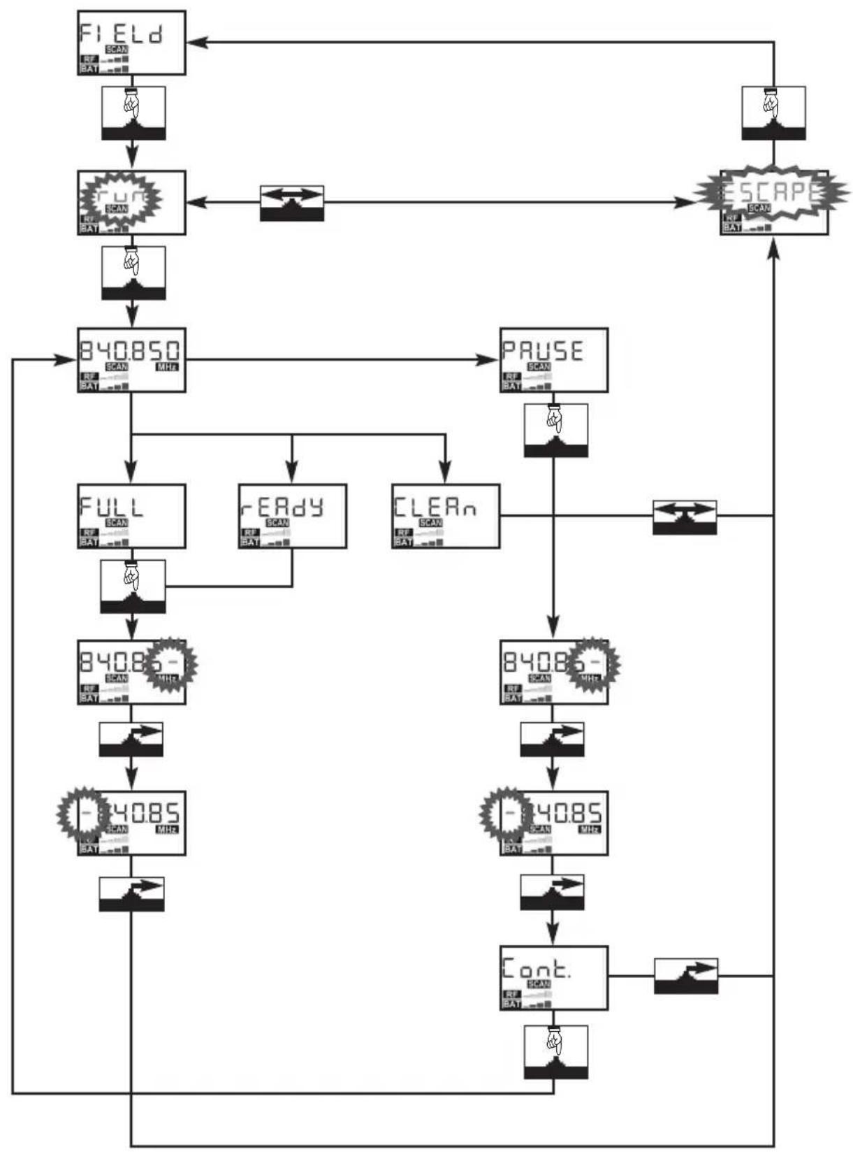
The Field Scan function automatically searches the receiver's entire frequency band for interference frequencies.
The frequency spacing for the automatic scan is 100 kHz. Any frequency whose field strength exceeds the factory-set fixed threshold is defined as an interference frequency and saved in a scan list. Once the can is completed, you can retrieve the scan list.
The receiver can store a maximum of seven interference frequencies or three interference ranges with their upper and lower frequency limits. As soon as the end of the examined frequency range (Stop frequency) is reached or the scan list is full, the scan will stop automatically.
Refer to fig. A6 in he Appendix.
-
In SETUP mode, turn the setup control up or down to call up the "FIELD" screen.
-
Press the setup control briefly.
-
To start the scan, select "RUN"; to return to the "FIELD" screen, select "ESCAPE".
-
During the scan, the audio output is muted and the display indicates the frequencies in MHz as they are scanned.
-
Once the scan has reached the Stop frequency, the scan stops automatically and the message "READY" appears on the display. If no interference frequencies were found, the display will change to "CLEAN".
-
60 scroll through the scan list, press the setup control briefly and turn the setup control up briefly.
The last interference frequency is followed by the "ESCAPE" option (see step 2 above).
Interrupting the scan:
- You can interrupt the scan at any time by pressing the setup control briefly. The message "PAUSE" will appear on the display.
- To scroll through the scan list, press the setup control briefly and turn the setup control up briefly.
The last interference frequency is followed by the "CONT." option.
- To resume the scan, press the setup control briefly. The receiver will scan the rest of the frequency band.
- To stop the scan, turn the setup control up briefly. This will bring up the "ESCAPE" option.
Memory overflow:
If the scan list is full before the Stop frequency has been reached, the scan will stop automatically and the display will change to "FULL".
- Follow steps 1 through 4 in the paragraph on "Interrupting the scan" above.
Setting the Squelch Threshold
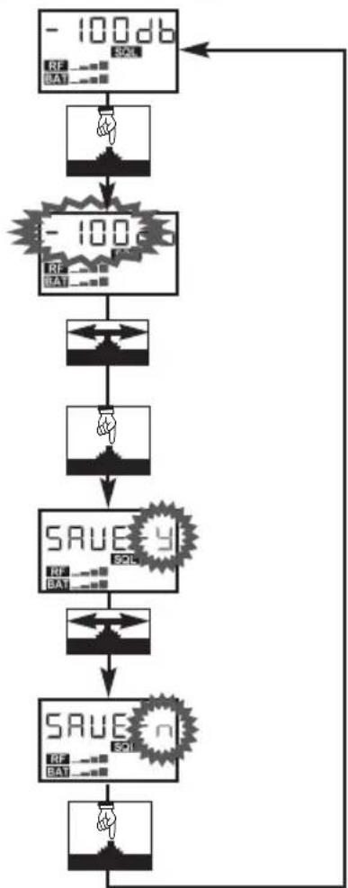
Refer to fig. A7 in the Appendix.
- You can set the squelch threshold from -100 dBm to -82 dBm in 6-dB increments (-100/-94/-88/-82).

Note
- Make sure never to set the squelch threshold any higher than absolutely necessary. The higher the squelch threshold (-100 dB = min., -86s dB = max.), the shorter the usable range between transmitter and receiver.
Hearing Protection Limiter
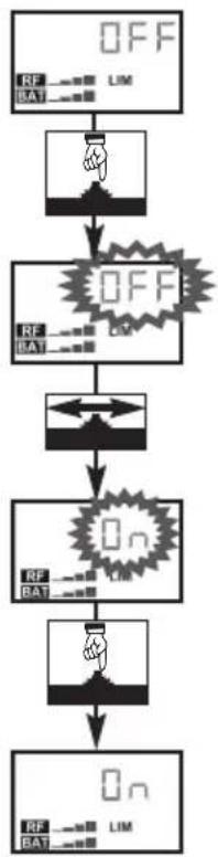
The hearing protection limiter places an absolute ceiling on the HP OUT headphones output level. Please note that the actual sound pressure at the ears will depend on the type of headphones used.
Refer to fig. A8 in the Appendix.
-
You can switch the limiter "ON" and "OFF".
-
To save your selection, press the setup control briefly.
-
To avoid hearing damage when using headphones, always leave the hearing protection limiter ON.
- The sensitivity of the human hearing system to aural stress differs from person to person. Therefore, AKG will not assume any liability for any damage to the user's hearing.

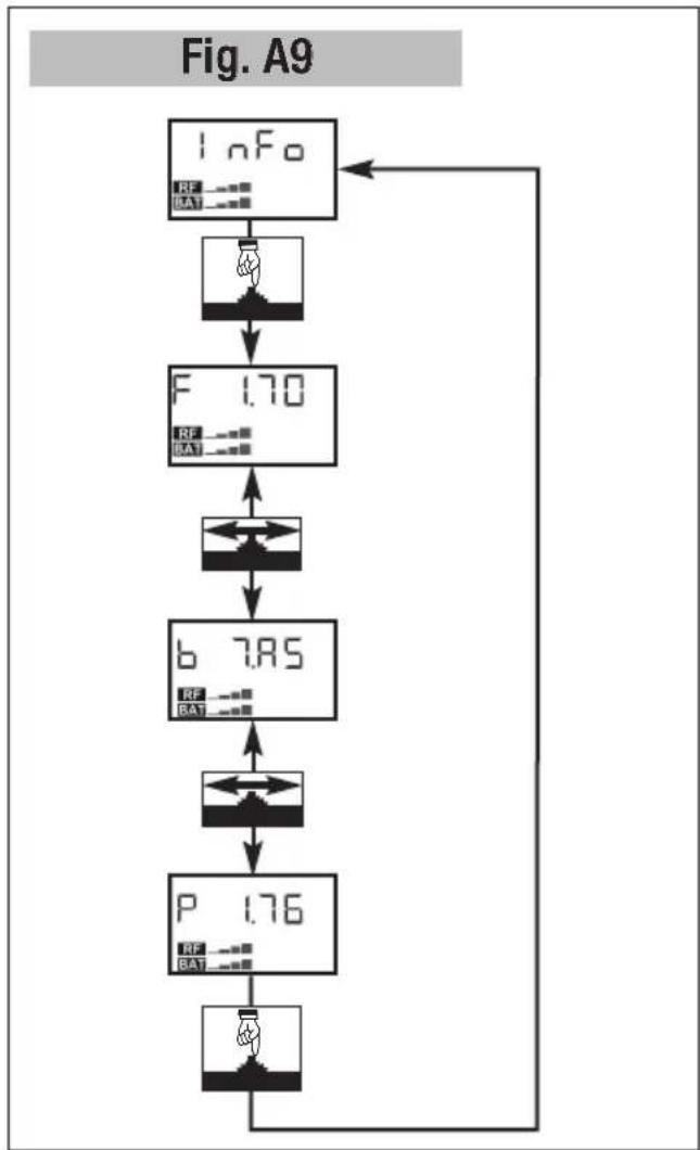
- You can call up the following details about your transmitter in this order:
- Firmware version (e.g., "F 2.30")
- Preset version (e.g., "P 1.76")
- Frequency band (e.g., "b 7.A5")
Info
Refer to fig. A9
in the Appendix.
5 Cleaning
- To clean the receiver surfaces, use a soft cloth moistened with water.
| Problem | Possible Cause | Remedy |
| No sound. | 1. No batteries inside transmitter.2. Transmitter and/or receiver is OFF.3. Transmitter is tuned to different frequency than receiver.4. No batteries inside receiver.5. Receiver batteries are not inserted properly.6. Receiver batteries/battery pack dead.7. Transmitter is too far away from receiver or squelch threshold setting is too high.8. Obstructions between transmitter and receiver.9. Transmitter too close to metal objects. | 1. Insert batteries into transmitter.2. Switch transmitter/receiver ON.3. Tune transmitter and receiver to same frequency.4. Insert batteries into receiver.5. Insert batteries conforming to "+" and "-" marks.6. Replace batteries/charge battery pack.7. Move closer to transmitter or choose lower squelch threshold setting.8. Remove obstructions.9. Remove objects or place transmitter further away. |
| Noise, crackling, unwanted signals. 1. Antenna location(s).2. Interference from other wireless systems, TV, radio, CB radios, or defective electrical appliances or installations. | 1. Relocate transmitter or receiver.2. Switch off interference sources or defective appliances or tune transmitter and receiver to a different frequency; have electrical installation checked. | |
| Distortion. • Interference from other wireless systems, TV, radio, CB radios, or defective electrical appliances or installations. | • Switch off interference sources or defective appliances or tune transmitter and receiver to a different frequency; have electrical installation checked. | |
| Momentary loss of sound ("dropouts") in some places. | • Antenna location(s). • Relocate transmitter or receiver. If dead spots persist, try to avoid them. | |
| Error Messages and Warnings Problem Remedy | ||
| "REC.ACC" • When charging BP4000, a recommended RECOVERY cycle was not run.Remaining battery life is not indicated. | • Press setup control briefly and run RECOVERY cycle next time you charge BP4000. | |
| "ERR.BAT" • Volume too high and battery voltage too low. The limiter is automatically activated to avoid premature power-down. | • Press setup control briefly to reset limiter to last active mode. Reduce volume or replace batteries/charge battery pack. | |
| "LO BAT" • Battery/BP4000 capacity lower than 20%. | • Replace batteries/charge BP4000. | |
| "NO RF" 1. Received signal level was too low for a moment (dropout).2. Radio signal still too weak after 10 seconds, warning comes up again. | 1. Press setup control briefly. (Warning disappears.)2. Relocate transmitter/antenna. If dropouts persist, mark and avoid critical spots. | |
| All other error messages ("ERR.XXX") | • Internal error. | 1. Switch power to receiver OFF and back ON after about 10 seconds.2. Contact your AKG dealer as soon as possible, even if problem appears to be corrected. |
Carrier frequency range: 500.1 to 821.5 MHz (several bands, depending on model)
RF bandwidth: up to 31.5 MHz, depending on band / 25 kHz
Modulation: FM
Audio formats: mono
Expander: compatible with WMS4500
Deemphasis: 150 μsecs.
Audio bandwidth: 35 Hz to 20 kHz
THD at 1 kHz: < 0.8% typ.
Signal/noise ratio (LINE OUT): 100 dB(A) typ.
Squelch threshold: -100, -94, -88, -82 dBm, selectable
Headphone output: 1/8" TRS jack
rated output level: 387 mV = 10 mW into 150 ohms
max. power: 100 mW/channel
signal/noise ratio: 90 dB(A) typ.
Line output: 2.5-mm TS jack
rated output level: 316 mV rms (-10 dBV)
output impedance: 600 ohms typ.
THD: < 0.5%
signal/noise ratio: 100 dB(A) typ.
Controls: ON/OFF button, setup control, backlit LCD, status LED, audio level LED
Power supply: 2 AA size dry batteries or BP4000 battery pack
Battery life: 6 to 12 hours
Operating temperature: -10^ to +50^
Size: 70 x 90 x 25 mm (2.8 x 3.5 x 1 in.)
Net weight inc. batteries: 165 g (5.8 oz.)
This product conforms to the standards listed in the Declaration of Conformity. To order a free copy of the Declaration of Conformity, visit http://www.akg.com or contact sales@akg.com.
flowchart
graph LR
    A["1"] --> B["Signal Transmission"]
    B --> C["Battery with Inverter"]
    C --> D["Disassembly"]
(Fonction "Field Scan")
flowchart
graph LR
    A["1"] --> B["Signal Transmission"]
    B --> C["Battery with Inverter"]
    C --> D["Disassembly"]
flowchart
graph LR
    A["1"] --> B["Signal Transmission"]
    B --> C["Battery with Inverter"]
    C --> D["Disassembly"]
Colocar as pilhas 89
6 Resolver problemas....95
Menus do receptor 97
Funcionalidades básicas (fig. A1 a A5) 98
flowchart
graph LR
    A["1"] --> B["Signal Transmission"]
    B --> C["Battery with USB cable"]
    C --> D["Disassembly with battery"]
    D --> E["Final Display with USB cable"]
Colocar as pilhas Veja fig. 3.
flowchart
graph TD
    A["NANE GFP CH\nAL7.01\nFREE\nRF\nRSAT"] --> B["840.850\nFREE\nRF\nRSAT"]
    B --> C["840.850\nFREE\nRF\nRSAT"]
    C --> D["840.850\nFREE\nRF\nRSAT"]
    D --> E["840.850\nFREE\nRF\nRSAT"]
    E --> F["SUE 9\nFREE\nRSAT"]
    F --> G["SUE n\nFREE\nRSAT"]
    G --> H["End"]
    B --> I["Hand icon"]
    C --> J["Hand icon"]
    D --> K["Hand icon"]
    E --> L["Hand icon"]
    F --> M["Hand icon"]
    G --> N["Hand icon"]
    H --> O["Hand icon"]
    I --> P["Arrow to right"]
    J --> Q["Arrow to left"]
    K --> R["Arrow to right"]
    L --> S["Arrow to left"]
    M --> T["Arrow to right"]
    N --> U["Arrow to left"]
Fig. A2
flowchart
graph TD
    A["UK"] --> B["BAT"]
    B --> C["840.850 MHz"]
    C --> D["BAT.BAT"]
    D --> E["NAME GRP CH RT7A01 FREE BAT"]
    A --> F["BAT.BAT"]
    F --> G["←"]
    G --> H["←"]
    H --> I["←"]
    I --> J["→"]
Fig. A4.1
flowchart
graph TD
    A["Input Signal: No Check"] --> B{Check Condition}
    B -->|Yes| C["Output Signal: Save"]
    B -->|No| D["End"]
    C --> E["Final Output: Save"]
    D --> F["Final Output: Save"]
Fig. A4.2
flowchart
graph TD
    A["Ruto"] --> B["REG"]
    B --> C["SCA"]
    C --> D["EPERE"]
    D --> E["ESCAPE"]
    A --> F["SAVE-y"]
    F --> G["SAVE-n"]
    G --> H["START"]
    H --> I["RE7A07"]
    I --> J["RESET"]
    J --> K["READ"]
    K --> L["RESET"]
    L --> M["RE7A01"]
    M --> N["RESET"]
    N --> O["READ"]
    O --> P["RE7A01"]
    P --> Q["RESET"]
    Q --> R["READ"]
    R --> S["RE7A01"]
    S --> T["RESET"]
    T --> U["READ"]
    U --> V["RE7A01"]
    V --> W["RESET"]
    W --> X["READ"]
    X --> Y["RE7A01"]
    Y --> Z["RESET"]
    Z --> AA["READ"]
    AA --> AB["RE7A01"]
    AB --> AC["RESET"]
    AC --> AD["READ"]
    AD --> AE["RE7A01"]
    AE --> AF["RESET"]
    AF --> AG["READ"]
    AG --> AH["RE7A01"]
    AH --> AI["RESET"]
    AI --> AJ["READ"]
    AJ --> AK["RE7A01"]
    AK --> AL["RESET"]
    AL --> AM["READ"]
    AM --> AN["RE7A01"]
    AN --> AO["RESET"]
    AO --> AP["READ"]
    AP --> AQ["RE7A01"]
    AQ --> AR["RESET"]
    AR --> AS["READ"]
    AS --> AT["RE7A01"]
    AT --> AU["RESET"]
    AU --> AV["READ"]
    AV --> AW["RE7A01"]
    AW --> AX["RESET"]
    AX --> AY["READ"]
flowchart
graph TD
    A["GRP Ruto"] --> B["NOCH13"]
    B --> C["SCAN"]
    C --> D["REPERE"]
    D --> E["ESCAPE"]
    F["TRUE 4"] --> G["NOT"]
    G --> H["TRUE n"]
    H --> I["NOT"]
    I --> J["Figure A4"]
    K["Figure A5"] --> L["NOT"]
    L --> M["Figure A4"]
Fig. A6
flowchart
graph TD
    A["FIELD\nREF. SCAN\nBAT...."] --> B["SCAN\nREF. BAT...."]
    B --> C["SCAN\nREF. BAT...."]
    C --> D["840850\nREF. BAT...."]
    D --> E["FULL\nREF. BAT...."]
    E --> F["84085-SCAN\nBAT...."]
    F --> G["-84085\nSCAN\nBAT...."]
    G --> H["CONT.\nREF. BAT...."]
    H --> I["SCAN\nBAT...."]
    I --> J["ESCAPE\nREF. BAT...."]
    J --> K["SCAN\nBAT...."]
    K --> L["PRESE\nREF. BAT...."]
    L --> M["READy\nREF. BAT...."]
    M --> N["CLEAN\nREF. BAT...."]
    N --> O["84085-SCAN\nBAT...."]
    O --> P["-84085\nSCAN\nBAT...."]
    P --> Q["CONT.\nREF. BAT...."]
    Q --> R["PRESE\nREF. BAT...."]
    R --> S["ESCAPE\nSCAN\nBAT...."]
    S --> T["PRESE\nREF. BAT...."]
Fig. A7
flowchart
graph TD
    A["- 100db\nRF BAT"] --> B["100dB"]
    B --> C["100dB"]
    C --> D["SAVE y\nRF BAT"]
    D --> E["SAVE y\nRF BAT"]
    E --> F["SAVE y\nRF BAT"]
    F --> G["SAVE y\nRF BAT"]
    G --> H["SAVE y\nRF BAT"]
    H --> I["SAVE y\nRF BAT"]
    I --> J["SAVE y\nRF BAT"]
    J --> K["SAVE y\nRF BAT"]
    K --> L["SAVE y\nRF BAT"]
    L --> M["SAVE y\nRF BAT"]
    M --> N["SAVE y\nRF BAT"]
    N --> O["SAVE y\nRF BAT"]
    O --> P["SAVE y\nRF BAT"]
    P --> Q["SAVE y\nRF BAT"]
    Q --> R["SAVE y\nRF BAT"]
    R --> S["SAVE y\nRF BAT"]
    S --> T["SAVE y\nRF BAT"]
    T --> U["SAVE y\nRF BAT"]
    U --> V["SAVE y\nRF BAT"]
    V --> W["SAVE y\nRF BAT"]
    W --> X["SAVE y\nRF BAT"]
    X --> Y["SAVE y\nRF BAT"]
    Y --> Z["SAVE y\nRF BAT"]
    Z --> AA["SAVE y\nRF BAT"]
    AA --> AB["SAVE y\nRF BAT"]
    AB --> AC["SAVE y\nRF BAT"]
    AC --> AD["SAVE y\nRF BAT"]
    AD --> AE["SAVE y\nRF BAT"]
    AE --> AF["SAVE y\nRF BAT"]
    AF --> AG["SAVE y\nRF BAT"]
    AG --> AH["SAVE y\nRF BAT"]
    AH --> AI["SAVE y\nRF BAT"]
    AI --> AJ["SAVE y\nRF BAT"]
    AJ --> AK["SAVE y\nRF BAT"]
    AK --> AL["SAVE y\nRF BAT"]
    AL --> AM["SAVE y\nRF BAT"]
    AM --> AN["SAVE y\nRF BAT"]
    AN --> AO["SAVE y\nRF BAT"]
    AO --> AP["SAVE y\nRF BAT"]
    AP --> AQ["SAVE y\nRF BAT"]
    AQ --> AR["SAVE y\nRF BAT"]
    AR --> AS["SAVE y\nRF BAT"]
    AS --> AT["SAVE y\nRF BAT"]
    AT --> AU["SAVE y\nRF BAT"]
    AU --> AV["SAVE y\nRF BAT"]
    AV --> AW["SAVE y\nRF BAT"]
    AW --> AX["SAVE y\nRF BAT"]
    AX --> AY["SAVE y\nRF BAT"]
    AY --> AZ["SAVE y\nRF BAT"]
    AZ --> BA["SAVE y\nRF BAT"]
    BA --> BB["SAVE y\nRF BAT"]
    BB --> BC["SAVE y\nRF BAT"]
    BC --> BD["SAVE y\nRF BAT"]
    BD --> BE["SAVE y\nRF BAT"]
    BE --> BF["SAVE y\nRF BAT"]
    BF --> BG["SAVE y\nRF BAT"]
    BG --> BH["SAVE y\nRF BAT"]
    BH --> BI["SAVE y\nRF BAT"]
    BI --> BJ["SAVE y\nRF BAT"]
    BJ --> BK["SAVE y\nRF BAT"]
    BK --> BL["SAVE y\nRF BAT"]
    BL --> BM["SAVE y\nRF BAT"]
    BM --> BN["SAVE y\nRF BAT"]
    BN --> BO["SAVE y\nRF BAT"]
    BO --> BP["SAVE y\nRF BAT"]
    BP --> BQ["SAVE y\nRF BAT"]
    BQ --> BR["SAVE y\nRF BAT"]
    BR --> BS["SAVE y\nRF BAT"]
    BS --> BT["SAVE y\nRF BAT"]
    BT --> BU["SAVE y\nRF BAT"]
    BU --> BV["SAVE y\nRF BAT"]
    BV --> BW["SAVE y\nRF BAT"]
    BW --> BX["SAVE y\nRF BAT"]
    BX --> BY["SAVE y\nRF BAT"]
    BY --> BZ["SAVE y\nRF BAT"]
    BZ --> CA["SAVE y\nRF BAT"]
    CA --> CB["SAVE y\nRF BAT"]
    CB --> CC["SAVE y\nRF BAT"]
    CC --> CD["SAVE y\nRF BAT"]
    CD --> CE["SAVE y\nRF BAT"]
    CE --> CF["SAVE y\nRF BAT"]
    CF --> CG["SAVE y\nRF BAT"]
    CG --> CH["SAVE y\nRF BAT"]
    CH --> CI["SAVE y\nRF BAT"]
    CI --> CJ["SAVE y\nRF BAT"]
    CJ --> CK["SAVE y\nRF BAT"]
    CK --> CL["SAVE y\nRF BAT"]
    CL --> CM["SAVE y\nRF BAT"]
    CM --> CN["SAVE y\nRF BAT"]
    CN --> CO["SAVE y\nRF BAT"]
    CO --> CP["SAVE y\nRF BAT"]
    CP --> CQ["SAVE y\nRF BAT"]
    CQ --> CR["SAVE y\nRF BAT"]
    CR --> CS["SAVE y\nRF BAT"]
    CS --> CT["SAVE y\nRF BAT"]
    CT --> CU["SAVE y\nRF BAT"]
    CU --> CV["SAVE y\nRF BAT"]
    CV --> CW["SAVE y\nRF BAT"]
    CW --> CX["SAVE y\nRF BAT"]
    CX --> CY["SAVE y\nRF BAT"]
    CY --> CZ["SAVE y\nRF BAT"]
    CZ --> DA["SAVE y\nRF BAT"]
    DA --> DB["SAVE y\nRF BAT"]
    DB --> DC["SAVE y\nRF BAT"]
    DC --> DD["SAVE y\nRF BAT"]
    DD --> DE["SAVE y\nRF BAT"]
    DE --> DF["SAVE y\nRF BAT"]
    DF --> DG["SAVE y\nRF BAT"]
    DG --> DH["SAVE y\nRF BAT"]
    DH --> DI["SAVE y\nRF BAT"]
    DI --> DJ["SAVE y\nRF BAT"]
Fig. A8
flowchart
graph TD
    A["OFF"] --> B["OFF"]
    B --> C["On"]
    C --> D["Off"]
    D --> E["Off"]
    style A fill:#f9f,stroke:#333
    style B fill:#ccf,stroke:#333
    style C fill:#cfc,stroke:#333
    style D fill:#fcc,stroke:#333
    style E fill:#ffc,stroke:#333
flowchart
graph TD
    A["I nFo"] --> B["RF BAT"]
    B --> C["F 1.70"]
    C --> D["↔"]
    D --> E["b 7.85"]
    E --> F["P 1.76"]
    F --> G["↔"]
    G --> H["↔"]
    H --> I["↔"]
    I --> J["↔"]
    J --> K["↔"]
    K --> L["↔"]
    L --> M["↔"]
    M --> N["↔"]
    N --> O["↔"]
    O --> P["↔"]
    P --> Q["↔"]
    Q --> R["↔"]
    R --> S["↔"]
    S --> T["↔"]
    T --> U["↔"]
    U --> V["↔"]
    V --> W["↔"]
    W --> X["↔"]
    X --> Y["↔"]
    Y --> Z["↔"]
    Z --> AA["↔"]
    AA --> AB["↔"]
    AB --> AC["↔"]
    AC --> AD["↔"]
    AD --> AE["↔"]
    AE --> AF["↔"]
    AF --> AG["↔"]
    AG --> AH["↔"]
    AH --> AI["↔"]
    AI --> AJ["↔"]
    AJ --> AK["↔"]
    AK --> AL["↔"]
    AL --> AM["↔"]
    AM --> AN["↔"]
    AN --> AO["↔"]
    AO --> AP["↔"]
    AP --> AQ["↔"]
    AQ --> AR["↔"]
    AR --> AS["↔"]
    AS --> AT["↔"]
    AT --> AU["↔"]
    AU --> AV["↔"]
    AV --> AW["↔"]
    AW --> AX["↔"]
    AX --> AY["↔"]
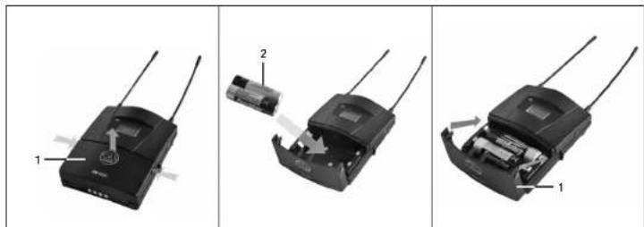
Fig.3
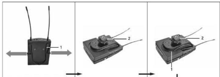
Fig.6
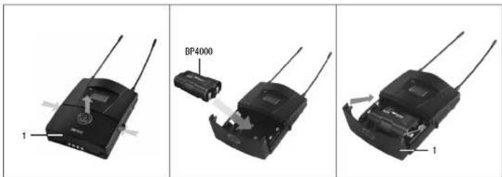
Fig.4
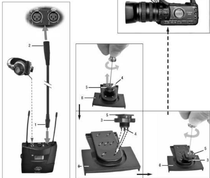
Fig.8
Fig.7
natural_image
Three-panel black-and-white photo showing a handheld device with multiple antennas, held by hands in a human head (no visible text or symbols)Fig.5
Microphones · Headphones · Wireless Microphones · Wireless Headphones · Headsets · Electroacoustical Components
For other products and distributors worldwide visit www.akg.com



ROHS OK
Printed in Hungary. 06/12/9100 U 13200

- Safety and Environment....21
- Description 23
- Setting Up 25
- Advanced Functions....30
- Cleaning....31
- Troubleshooting....32
- Specifications....33
- Appendix....97
- Symbols Used in the Manual
- Display Characters
- High Volume
- Safety and Environment
- FCC Statement
- Description
- Status LED
- Display
- Setting Up the Receiver
- Setting Up
- Frequency Selection
- Selecting the Country Preset
- Manual Selection in MHz
- Manual Selection from a Preset
- Automatic Selection for a Single-channel System
- Automatic Selection for a Multichannel System
- Powering Down
- Mounting the Receiver
- Belt Clip
- Hot-shoe Adapter
- Finding Interference Frequencies
- Setting the Squelch Threshold
- Hearing Protection Limiter
- Info
- Cleaning
- ROHS OK
Brand : AKG
Model : PR4500
Category : Receiver