
Sani-Towel - Oven Eurom - Free user manual and instructions
Find the device manual for free Sani-Towel Eurom in PDF.


| Product type | Oven (cooking appliance) |
| Brand | Eurom |
| Model | Sani-Towel |
| Dimensions (W × D × H) | 50 × 40 × 30 cm |
| Weight | 8 kg |
| Power supply | 220-240 V ~ 50/60 Hz |
| Power | 1500 W |
| Capacity | 30 liters |
| Exterior material | Stainless steel |
| Heat type | Natural convection |
| Number of functions | 5 (grill, convection, bottom heat, top heat, defrost) |
| Timer | Yes, up to 120 minutes with audible signal |
| Temperature range | 50 °C – 250 °C |
| Interior lighting | Yes |
| Door | Removable tempered glass |
| Cleaning | Soft damp cloth and mild detergent |
| Safety | Automatic shut-off in case of overheating, double-glazed door |
| Included accessories | Grid, drip pan, safety handle |
| Repairability | Spare parts available through after-sales service |
Frequently Asked Questions - Sani-Towel Eurom
User questions about Sani-Towel Eurom
0 question about this device. Answer the ones you know or ask your own.
Ask a new question about this device
Download the instructions for your Oven in PDF format for free! Find your manual Sani-Towel - Eurom and take your electronic device back in hand. On this page are published all the documents necessary for the use of your device. Sani-Towel by Eurom.
USER MANUAL Sani-Towel Eurom
natural_image
White horizontal heater with multiple slats and a small digital display at the bottom (no text or symbols on the heater itself)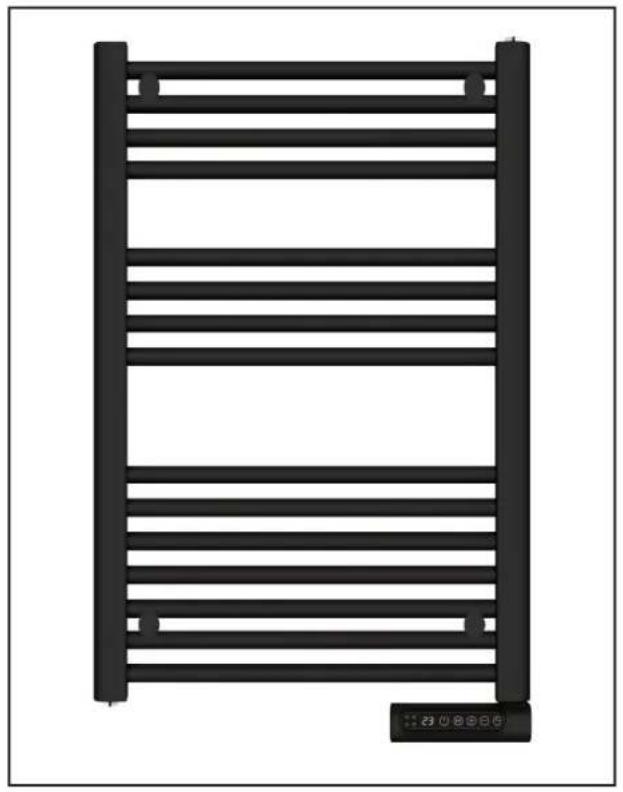
natural_image
Black horizontal ladder structure with a small digital display icon at the bottom right corner (no text or symbols on the ladder itself)Sani-Towel
White: 500 Watt Art.nr. 352450-352467 (Swiss plug)
750 Watt Art.nr. 352474-352481 (Swiss plug)
Black: 500 Watt Art.nr. 352528-352535 (Swiss plug)
750 Watt Art.nr. 352542-352559 (Swiss plug)
| Informatie eisen voor elektrische toestellen voor lokale ruimteverwarming | |||||
| Model: Sani-Towel 500 | |||||
| Item | Symbool | Waarde | Eenheid | Item | Eenheid |
| Warmteafgifte | Type warmte-input, uitsluitend voor elektrische warmte opslagtoestellen (selecteer één) | ||||
| Nominale warmteafgifte | Pnom | 0,5 | kW | Handmatige sturing van de warmteopslag met geïntegreerde thermostaat | Niet toepasbaar |
| Minimale warmteafgifte (indicatief | Pmin | N/A | kW | Handmatige sturing van de warmteopslag met kamer- en/of buitentemperatuur feedback | Niet toepasbaar |
| Maximale continue warmteafgifte | Pmax,c | 0,493 | kW | Elektrische sturing van de warmteopslag met kamer- en/of buitentemperatuur feedback | Niet toepasbaar |
| Aanvullend elektriciteitsverbruik | Door een ventilator bijgestane warmteafgifte | Niet toepasbaar | |||
| Bij nominale warmteafgifte | elmax | 0,000 | kW | Type warmteafgifte/sturing kamertemperatuur (selecteer één) | |
| Bij minimale warmteafgifte | elmin | 0,000 | kW | Eentrapswarmteafgifte, geen sturing van de kamertemperatuur | Neen |
| In stand-by modus | eISB | 0,000201 | kW | Twee of meer handmatig in te stellen trappen, geen sturing van de kamertemperatuur | Neen |
| Mechanische sturing van de kamertemperatuur door thermostaat | Neen | ||||
| Model: Sani-Towel 750 | Elektronische sturing van de kamertemperatuur | Neen | |||
| Item | Symbool | Waarde | Eenheid | Elektronische sturing van de kamertemperatuur plus dag-tijdschakelaar | Neen |
| Warmteafgifte | Elektronische sturing van de kamertemperatuur plus week-tijdschakelaar | Ja | |||
| Nominale warmteafgifte | Pnom | 0,8 | kW | Andere sturingsopties (meerdere selecties mogelijk) | |
| Minimale warmteafgifte (indicatief | Pmin | N/A | kW | Sturing van de kamertemperatuur, met aanwezigheidsdetectie | Neen |
| Maximale continue warmteafgifte | Pmax,c | 0,741 | kW | Sturing van de kamertemperatuur, met openraamdetectie | Ja |
| Aanvullend elektriciteitsverbruik | Met de optie van afstandsbediening | Neen | |||
| Bij nominale warmteafgifte | elmax | 0,000 | kW | Met adaptieve sturing van de start | Neen |
| Bij minimale warmteafgifte | elmin | 0,000 | kW | Met beperking van de werkingstijd | Neen |
| In stand-by modus | eISB | 0,000201 | kW | Met black-bultsensor | Neen |
| Contactgegevens | Eurom - Kokosstraat 20 - 8281JC - Genemuiden - The Netherlands | ||||
| Erforderliche Angaben zu elektrischen Einzelraumheizgeräten | |||||
| Modell: Sani-Towel 500 | |||||
| Angabe | Symbol | Wert | Einheit | Angabe | Einheit |
| Wärmeleistung | Nur bei elektrischen Speicher-Einzelraumheizgeräten: Art der Regelung der Wärmezufuhr (bitte eine Möglichkeit auswählen) | ||||
| Nennwärmeleistung | Pnom | 0,5 | kW | Manuelle Regelung der Wärmezufuhr mit integriertem Thermostat | Unzutreffend |
| Mindestwärme-leistung (Richtwert) | Pmin | N/A | kW | Manuelle Regelung der Wärmezufuhr mit Rückmeldung der Raum- und/oder Außertemperatur | Unzutreffend |
| Maximale kontinierliche Wärmeleistung | Pmax,c | 0,493 | kW | Elektronisch Regelung der Wärmezufuhr mit Rückmeldung der Raum- und/oder Außertemperatur | Unzutreffend |
| Hilfsstromverbrauch | Wärmeabgabe mit Gebläse-unterstützung | Unzutreffend | |||
| Bei Nennwärmeleistung | elmax | 0,000 | kW | Art der Wärmeleistung / Raumtemperaturkontrolle (bitte eine Möglichkeit auswählen) | |
| Bei Mindestwärme-Leistung | elmin | 0,000 | kW | Einstufige Wärmeleistung, keine Raumtemperaturkontrolle | Nein |
| Im Bereitschafts-zustand | elSB | 0,000201 | kW | Zwei oder mehr manuell einstellbare Stufen, keine Raum-Temperatur Kontrolle | Nein |
| Raumtemperaturkontrolle mit mechanischem Thermostat | Nein | ||||
| Modell: Sani-Towel 750 | Mit Elektronische Raum-Temperatur Kontrolle | Nein | |||
| Angabe | Symbol | Wert | Einheit | Elektronische Raumtemperaturkontrolle und Tageszeitregelung | Nein |
| Wärmeleistung | Elektronische Raumtemperaturkontrolle und Wochentags Regelung | Ja | |||
| Nennwärmeleistung | Pnom | 0,8 | kW | Sonstige Regelungsoptionen (Mehrfach-nennungen möglich) | |
| Mindestwärme-leistung (Richtwert) | Pmin | N/A | kW | Raumtemperaturkontrolle mit Präsenzerkennung | Nein |
| Maximale kontinierliche Wärmeleistung | Pmax,c | 0,741 | kW | Raumtemperaturkontrolle mit Erkennung offener Fenster | Ja |
| Hilfsstromverbrauch | Mit Fernbedienungsoption | Nein | |||
| Bei Nennwärmeleistung | elmax | 0,000 | kW | Mit adaptiver Regelung des Heizbeginns | Nein |
| Bei Mindestwärme-Leistung | elmin | 0,000 | kW | Mit Betriebzeitbegrenzung | Nein |
| Im Bereitschafts-zustand | elSB | 0,000201 | kW | Mit Schwarzkugelsensor | Nein |
| Kontaktangaben | Eurom - Kokosstraat 20 - 8281 JC - Genemuiden - The Netherlands | ||||
| Information requirement for the electric local space heaters | |||||
| Model identifier(s): Sani-Towel 500 | |||||
| Item | Symbol | Value | Unit | Item | Unit |
| Heat output | Type of heat input, for electric storage local space heaters only (select one) | ||||
| Nominal heat output | Pnom | 0,5 | kW | manual heat charge control, with integrated thermostat | Not applicable |
| Minimum heat output (indicative) | Pmin | N/A | kW | manual heat charge control with room and/or outdoor temperature feedback | Not applicable |
| Maximum continuous heat output | Pmax,c | 0,493 | kW | electronic heat charge control with room and/or outdoor temperature feedback | Not applicable |
| Auxiliary electricity consumption | fan assisted heat output | Not applicable | |||
| At nominal heat output | elmax | 0,000 | kW | Type of heat output/room temperature control (select one) | |
| At minimum heat output | elmin | 0,000 | kW | single stage heat output and no room temperature control | No |
| In standby mode | eISB | 0,000201 | kW | Two or more manual stages, no room temperature control | No |
| with mechanic thermostat room temperature control | No | ||||
| Model identifier(s): Sani-Towel 750 | with electronic room temperature control | No | |||
| Item | Symbol | Value | Unit | electronic room temperature control plus day timer | No |
| Heat output | electronic room temperature control plus week timer | Yes | |||
| Nominal heat output | Pnom | 0,8 | kW | Other control options (multiple selections possible) | |
| Minimum heat output (indicative) | Pmin | N/A | kW | room temperature control, with presence detection | No |
| Maximum continuous heat output | Pmax,c | 0,741 | kW | room temperature control, with open window detection | Yes |
| Auxiliary electricity consumption | with distance control option | No | |||
| At nominal heat output | elmax | 0,000 | kW | with adaptive start control | No |
| At minimum heat output | elmin | 0,000 | kW | with working time limitation | No |
| In standby mode | eISB | 0,000201 | kW | with black bulb sensor | No |
| Contact details | Eurom - Kokosstraat 20 - 8281 JC - Genemuiden - The Netherlands | ||||
| Exigences d'information applicables aux dispositifs de chauffage décentralisés électriques | |||||
| Modèle: Sani-Towel 500 | |||||
| Caractéristique | Symbole | Valeur | Unité | Caractéristique | Unité |
| Puissance thermique | Type d'apport de chaleur, pour les dispositifs de chauffage décentralisés électriques à accumulation uniquement (sélectionner un seul type | ||||
| Puissance thermique nominale | Pnom | 0,5 | kW | Contrôle thermique manuel de la charge avec thermostat intégré | n'est pas applicable |
| Puissance thermique minimale (indicative) | Pmin | N/A | kW | Contrôle thermique manuel de la charge avec réception d'informations sur la température de la pièce et/ou extérieure | n'est pas applicable |
| Puissance thermique maximale continue | Pmax,c | 0,493 | kW | contrôle thermique électronique de la charge avec réception d'informations sur la température de la pièce et/ou extérieure | n'est pas applicable |
| Consommation d'électricité auxiliaire | Puissance thermique réglable par ventilateur | n'est pas applicable | |||
| À la puissance thermique nominale | elmax | 0,000 | kW | Type de contrôle de la puissance thermique/de la température de la pièce (sélectionner un seul type) | |
| À la puissance thermique minimale | elmin | 0,000 | kW | Contrôle de la puissance thermique à un palier, pas de contrôle de la température de la pièce | Non |
| En mode veille | eISB | 0,000201 | kW | Contrôle à deux ou plusieurs paliers manuels, pas de contrôle de la température de la pièce | Non |
| Contrôle de la température de la pièce avec thermostat mécanique | Non | ||||
| Modèle: Sani-Towel 750 | Contrôle électronique de la température de la pièce | Non | |||
| Caractéristique | Symbole | Valeur | Unité | Contrôle électronique de la température et programmateur journalier | Non |
| Puissance thermique | Contrôle électronique de la température et programmateur hebdomadaire | Qui | |||
| Puissance thermique nominale | Pnom | 0,8 | kW | Autres options de contrôle (sélectionner une ou plusieurs options) | |
| Puissance thermique minimale (indicative) | Pmin | N/A | kW | Contrôle de la température de la pièce, avec détecteur de présence | Non |
| Puissance thermique maximale continue | Pmax,c | 0,741 | kW | Contrôle de la température de la pièce, avec détecteur de fenêtre ouverts | Oui |
| Consommation d'électricité auxillaire | Option contrôle à distance | Non | |||
| À la puissance thermique nominale | elmax | 0,000 | kW | Contrôle adaptatif de l'activation | Non |
| À la puissance thermique minimale | elmin | 0,000 | kW | Limitation de la durée d'activation | Non |
| En mode veille | eISB | 0,000201 | kW | Capteur à globe noir | Non |
| Coordonnées de contact | Eurom - Kokosstraat 20 - 8281 JC - Genemuiden - The Netherlands | ||||
Dank
natural_image
Simple black-and-white diagram of a container with a lid and a label 'Zone 3' above it, no other text or symbols present.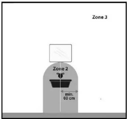
Waarschuwingen elektrische kachels
natural_image
Symbol of a trash bin crossed with no visible text or labelsnatural_image
Simple black silhouette of a bowl with a lid, placed on a gray surface labeled 'Zone 3' (no other text or symbols)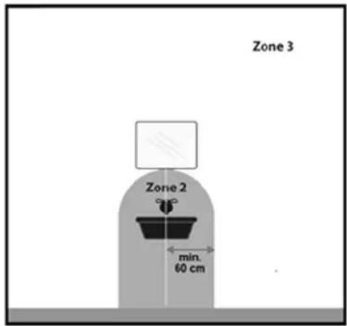
natural_image
Symbol of a trash bin with crossed lines indicating no waste or discharge, and a solid black rectangle below (no text or labels)Thank you very much for choosing for a EUROM device. You have made a good choice! We hope you will be satisfied about its functioning. To get maximum profit from your product, it is important to read this manual attentive and totally before use, and to understand what is written. Read especially the safety instructions: they are there to protect you and your environment. Keep the manual in a safe place for future reference. Store also the package: that is the best protection for your product in times of no-use. And if you at any time pass the appliance on, pass on the manual and package too.
We hope enjoy the the Sani-Towel!
Eurom
Kokosstraat 20
8281 JC Genemuiden (NL)
info@eurom.nl
www.eurom.nl
This manual has been complied with the utmost care. Nevertheless, we reserve the right to optimize this manual at any time and to adjust it technically. The image used may differ.
Technical data
| Type | Sani-Towel 500 | Sani-Towel 750 |
| Supply Voltage | 220-240V~50Hz | |
| Capacity | 500 W | 750 W |
| Protection class | IP24 | |
| Thermostat | + | |
| Dimensions | 50 x 5 x 85 cm | 50 x 5 x 105 cm |
| Weight | 9,7 kg | 12,1 kg |
Is it possible to have an electric heater in the bathroom?
Yes, it is safe if you adhere to the following 3 rules when installing the Eurom bathroom heater.
Rule 1
The Eurom bathroom heater must be securely mounted in a fixed position. A movable heater may never be used in the bathroom. No matter what classification or IP value a movable heater has: a movable stove never suitable for the bathroom.
Rule 2
When choosing a permanent location for the Eurom bathroom heater, you should keep in mind that the controls of the bathroom heater may never be operated by a person in the bath or under the shower. So always keep sufficient distance between the bathroom heater and the bath and shower room.
Rule 3
The Eurom bathroom heater may be mounted in zone 3 only.
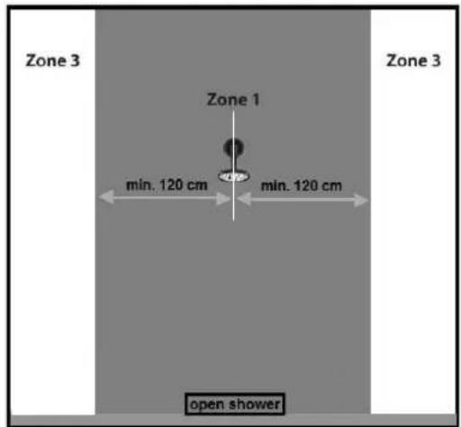
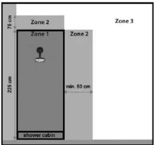
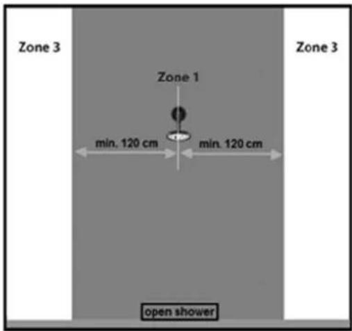
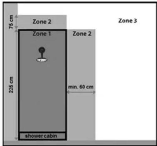
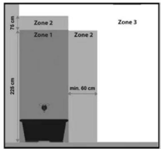
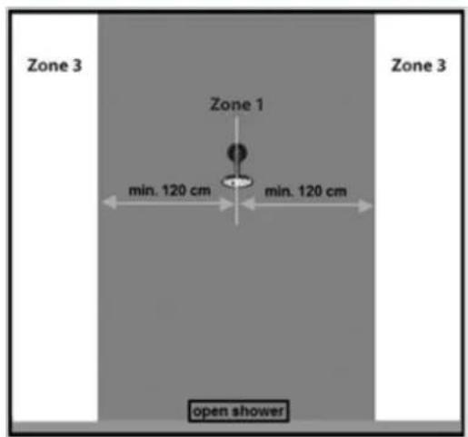
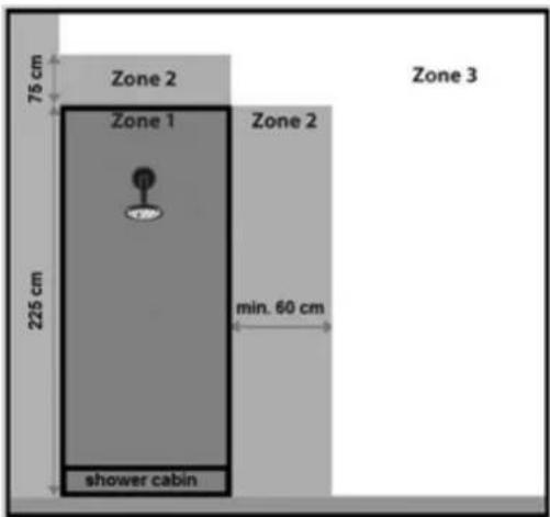
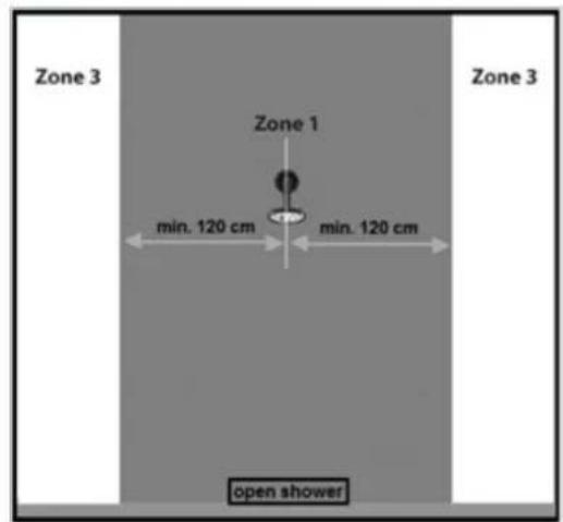
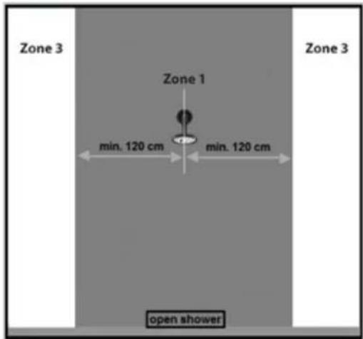
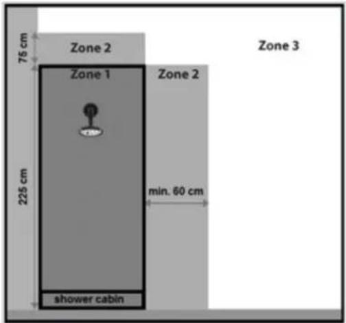
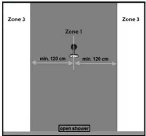
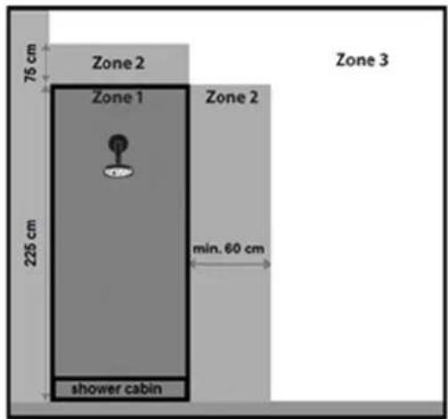
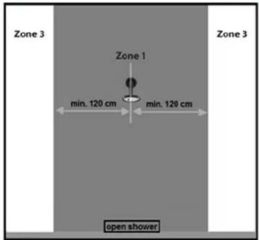
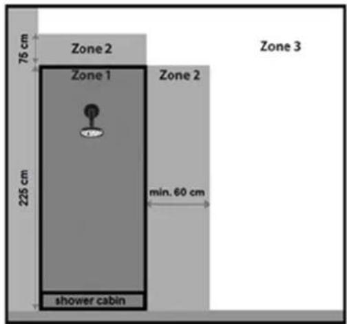
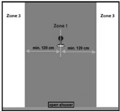
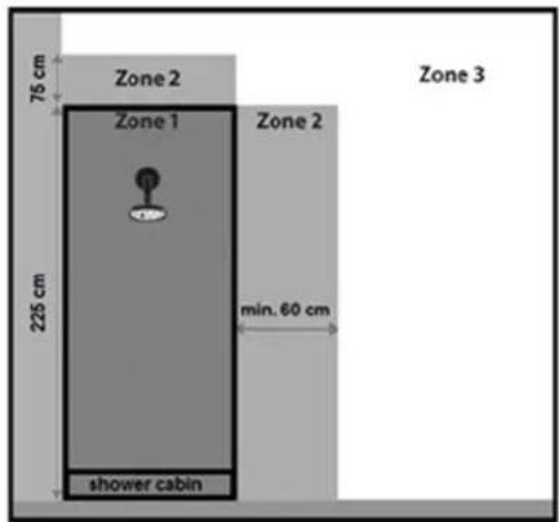
A bathroom has a zone layout with 4 different zones (see the drawing).
Zone 0 The space in the bath and in the shower tray.
Zone 1 option 1: with shower cubicle / with bath-wall partition
The space above the bath and above the shower tray (up to a max. of 225 cm from the ground)
option 2: No shower cubicle / No bath-wall partition (a curtain is not a partition!)
The space above the bath and above the shower tray (up to a max. of 225 cm from the ground) plus the space next to the bath and shower tray with a radius of 120 cm. Calculated from the edge of the bath and the edge of the shower tray.
Zone 2 option 1: with shower cubicle / with bath-wall partition
The space next to the bath and shower tray with a radius of 60 cm.
Calculated from the edge of the bath and the edge of the shower tray.
option 2: no shower cubicle / no bath-wall partition (a curtain is not a partition!)
In this situation, there is no zone 2
The 60 cm space around the washbasin tap
Zone 3- Other space
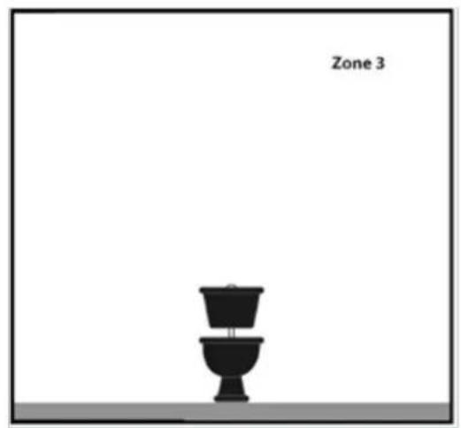
natural_image
Simple black silhouette of a bowl with a lid, placed on a gray surface labeled 'Zone 3' (no other text or symbols)
Warning electric cables
Safety warning - general
- Read the user instructions carefully and completely before using (and installing) this device. Keep the instruction leaflet somewhere safe so that you can consult it and pass it on in future.
- Before use, check your new device (including cable and plug) for any visible damage. Never use a damaged device but take it back to the supplier for a replacement.
- In the event of incorrect usage or installation, there is a risk of electric shocks and/or a fire hazard.
Warnings device position
- Do not use the device before it has been fully installed as set out in the user instructions. Never use the device standing up or leaning against something, or similar. Never insert the plug into the socket before the device has been correctly installed at the appropriate place.
- When installing, the following minimum distances should be considered:
Minimum distance to ceiling: 15 cm
Minimum distance to side walls: 15 cm
Minimum distance to the ground: 60 cm
Minimum distance to the front: 50 cm
- The air around the device must be able to circulate freely. Never install it too close to large objects and never under a shelf, cupboard, curtains or similar. The minimum distances from large objects such as shelves, cupboards, etc. to the top, sides and underneath of the device are equal to the aforementioned minimum distances to ceilings, side walls and the ground, respectively.
- This device is suitable for installation in damp spaces such as bathrooms, wash rooms etc. (IP24). The device may only be used in the bathroom if it is installed at a fixed point and the device is at least 60 centimetres from water-points and water reservoirs (tap, bath, shower, toilet, sink, swimming pool, etc.) (see drawing zone 3 at explanation Installation). Make sure that no water can fall on it and that it cannot be penetrated by water. If the device does get wet make sure you remove the plug from the socket! Do not use a device that is wet inside but take it to be repaired. Never immerse
the device, cable or plug in water or any other fluid and never touch device with wet hands.
- If the device is installed in a bathroom, it must be installed such that the switches and other operating components cannot be touched by a person in the bath or shower.the ground, whether secured to the wall or ceiling.
- The wall to which the device is secured and the ceiling and walls within 1 metre of the device must not be made of flammable materials. Materials must be resistant to temperatures of at least 125^ C without burning, melting, deforming or bursting into flames. Check regularly to ensure that the wall and ceiling are not overheating; this could be dangerous!
- Only use the device if it has been secured properly. Make sure that you always use attachment materials that are suitable for the surface you are working with; consult an expert if required.
- With wall installation: never block the space between the device and the wall.
- Never install this device behind a door or by an open window, where rain could get in.
- If this device is connected directly to your electrical installation, it must be installed by a specialist, taking into account the valid regulations/legislation.
- The installation must be equipped with a double pole switch with a minimum contact opening of 3 mm.
- Do not place the device near, under or facing an electrical socket and not in the vicinity of an open fire or heat source.
- Do not use the device nearby or facing furniture, curtains, paper or other flammable materials. Keep at least 1 metre from device!
- Do not use the heater outdoors or in areas that are smaller than 5 m^3 (Sani-Towel 500) and 7 m^3 (Sani-Towel 750).
- The device contains hot and/or glowing and sparking components. Do not, therefore, use where fuels, paint, flammable fluids and/or gases are stored. Do not use the device in an environment that poses a fire risk, e.g. near gas tanks, gas pipes or aerosols. This is an explosion and fire risk!
Warnings - use
- Do not use additions/accessories on the device that have not been supplied or approved by the manufacturer.
-
Only use the device for its intended purpose and in the manner set out in this instruction leaflet.
-
Some parts of this device will get very hot and could cause burns. You must pay particular attention to children, vulnerable persons and pets that are present near the device. Never leave them alone with a working device.
-
Never cover or block the device completely; it will overheat and this could lead to a fire risk.
-
Only use the horizontal tubes to dry towels, etc. Never hang towels etc. directly on the vertical parts of the appliance. Ensure that the device is not completely covered.
-
The device is exclusively intended for normal, household usage. Only use for providing heat in your home.
-
The connection voltage and frequency, as given on the device, must correspond to that of the socket to be used. The electrical socket to be used must be an earthed connection. The electrical installation must be protected via a 30 mA earth leakage circuit breaker. The electrical socket that you are using must be to hand at all times in order to be able to remove the plug from the socket in the event of an emergency.
-
To avoid overloading and/or fuses being blown, do not use any other equipment on the same socket as the one used for the device.
-
Unroll the electric cable for the device fully before inserting the plug into the socket and ensure that the electrical cable does not come into contact with the fireplace or get hot. Do not run the electrical cable under carpet, cover with mats, runners or similar and do not place in areas that are walked on frequently. Ensure that it cannot be stepped on and that no furniture is placed on top of it. Do not bend the electrical cable around sharp corners and do not roll up too tightly after use! Prevent the electrical cable coming into contact with oil, solvents and sharp objects. Check the cable and plug regularly for damage. Do not bend or pinch the electrical cable and do not wind it around the device; this could damage the insulation!
-
The use of an extension cable is not permitted in damp rooms.
-
Only connect the device to a fixed socket. The use of a multi-plug adapters or similar is not permitted.
-
During use, the plug may begin to feel warm; this is normal. If it's really warm, there may be something wrong with the socket. Please contact your electrician.
-
Always turn off the device and remove the plug from the power socket: Never turn the device off using the plug!
- Never leave a working device unattended but switch off and then remove the plug from the socket. Always remove the plug from the socket when the unit is not in use! Always remove plug by pulling on the plug itself; never pull on the electrical cable!
- Apart from manual use, this device can also be operated via a timer. However you operate it, make sure that the safety guidelines are taken into account at all times! Do not operate the device with an additional time clock, timer, volume control or any other device that automatically turns on the device.
- This device gets hot during use. Never touch the device when it is on or shortly thereafter; it could burn you.
- Never operate the device with wet hands.
Who can use the device?
- Children younger than 3 must be kept out of the vicinity of the device unless they are continuously supervised.
- Children between the ages of 3 and 8 may only switch the device on or off if it is set up or installed at its usual location and they are supervised or have received instructions regarding the safe use of the device and understand the corresponding hazards. Children between the ages of 3 and 8 may not insert the plug into the socket, adjust the device settings or clean or maintain it.
- This device can only be used by children from the age of 8 and elderly persons and persons with diminished physical or mental capacities or a lack of experience and expertise if they are supervised or have received instructions regarding the safe use of the device and understand the corresponding hazards.
- Children may not clean or maintain the device without supervision.
- Children may not play with the device.
Warnings for maintenance
- Keep the device clean. Dust, dirt and/or deposits in the device often lead to overheating. Ensure that this type of build-up is regularly removed.
-
Always switch the device off, remove plug from socket, turn off the double pole switch and let the device cool down before you:
-
clean the device
- users - maintain the device.
-
touch the device.
-
Never switch the device on if you have noticed damage to the device itself, the cable or plug or if it does not work properly, makes strange noises, smells odd or you can see smoke, or if it has fallen or shows any other signs of damage. Remove the plug from the socket immediately. Take the entire device back to your supplier or a recognised electrician to be checked and/or repaired. Always ask for original parts to be used.
- The device may only be opened and/or repaired by a competent and qualified person. Do not carry our your own repairs as this could be dangerous! Repairs carried out by unauthorised persons or changes made to the device could damage the dust/waterproof capacity of the device and will nullify the guarantee and the manufacturer's liability.
- If the electrical cable is damaged, it must be replaced by the manufacturer, their service department or somebody with similar qualifications in order to prevent creating a hazard.
Failing to adhere to points 3,4,5 could lead to damage, fire and/or personal injury. They will invalidate the guarantee and the supplier, importer and/or manufacturer shall not be liable for the consequences.
Description
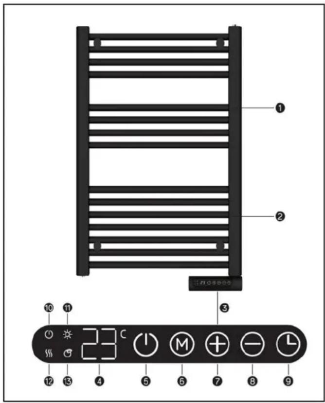
- Heating pipes
- Towel heaters
- Control panel with LED screen
- Temperature display
- Standby button
- Mode key
-
- Button: 'increase temperature'
-
- Button: 'decrease temperature'
- Timer setting button
- Standby indicator
- Comfort mode indicator
- Heating status indicator
- ECO mode indicator
Installation
- Remove all the packaging materials and keep out of children's reach.
- After removing the packaging, check whether the appliance shows any damage or any signs of faults/defects/failures. Do not use the appliance in case of doubt, but turn to your supplier for checking/replacement.
- Choose a solid, flat and perpendicular wall of non-flammable and non-melting material (i.e. not wood, synthetic material or suchlike!) to hang the heater on.
-
Choose an appropriate position for the appliance, taking into account all the precautionary measures stated in this instruction manual.
-
Mount the appliance according to the installation drawing supplied.
- For your own safety, choose a position where the appliance cannot be touched from the bath, shower or from behind the washbasin, etc.
- Your heater is now ready for use.
Using for the first time and operating
Make sure that the heater is switched off. Insert the plug into a correctly working 220-240V/50Hz socket or turn the double-pole switch on.
Switch on the heater by pressing the on/off button and the control lamp on the display will light up.
By pressing the ⚠ and/or buttons, you can set the desired temperature.
Day/time setting
- Press the button for 3 seconds ⏻ to set the day and time.
- The display shows 'd': press ⊕en ⊖to select the day.
| 1 | Monday |
| 2 | Tuesday |
| 3 | Wednesday |
| 4 | Thursday |
| 5 | Friday |
| 6 | Saturday |
| 7 | Sunday |
- Press the ⏻ button to confirm the day setting and enter the time setting: the display shows
- Press ⊕ and ⊖ to set the current hour.
- Press the ⏻ button to confirm the hour setting and enter the minute setting: the display shows
- Press ⊕ and ⊖ to set the current minutes.
- Press the button to confirm.
Please note: The day and time indications are reset to factory settings if there is no power.
Heating mode
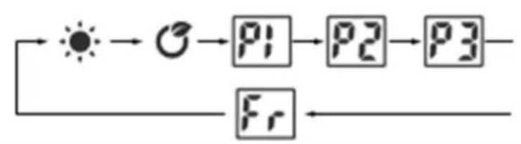
- Press the Ⓜ button to open the mode setting. Pressing the Ⓜ button, will run the heating mode through the continual cycle below:
flowchart
graph TD
    A["Sun"] --> B["C"]
    B --> C["P1"]
    C --> D["P2"]
    D --> E["P3"]
    E --> F["Fr"]
- Comfort mode; press ⊕ and ⊖ to set the temperature from 5°C-35°C.
• ECO mode; press ⊕ and ⊖ to set the temperature from 1°C-31°C. Please note: ECO mode = Comfort mode -4°C. - Fr Anti-freeze mode, target temperature in anti-freeze mode is 7°C. The temperature cannot be adjusted in this mode.
P1/P2/P3 setting heating program
Please note: images 1 to 5 are for illustrative purposes only, these images are not shown on the display.
Please note: if the day/time setting has not yet been completed or set, the first time you enter program setting P1/P2/P3, you will be asked to complete or set the day/time setting first.
P1
Monday-Sunday non-customisable program

Image 1
From 00:00-01:00am comfort mode, from 01:00-07:00am ECO mode and from 07:00-00:00am comfort modus.
P2
Monday-Friday and Saturday-Sunday (non-customisable program)
(Monday-Friday)

Image 2
From 00:00-01:00am Comfort mode, from 01:00-05:00am Eco mode, from 05:00-09:00am Comfort mode, from 09:00-19:00pm Eco mode, from 19:00-00:00am Comfort mode.
(Saturday-Sunday)

Image 3
From 00:00-01:00am comfort mode, from 01:00-08:00am ECO mode, from 08:00 uur-11:00am comfort mode, from 11:00-13:00pm ECO mode, from 13:00-16:00pm comfort mode, from 16:00-20:00pm ECO mode and from 20:00-00:00am comfort mode.
P3
Adjustable program setting
- When under P3 mode, press the Ⓜ button for 3 seconds to set the day.
-
The display shows; press and to set the days (Monday-7 Sunday). Press the Button to confirm and to enter the hour set
-
The display shows; press and to set the time from 00-24 hours.
-
Press Ⓜ to set the desired heating mode for every hour in comfort mode, ECO mode or no sign Anti-freeze mode.
-
Repeat the above 4 points until you have completed the program for each day and hour. Please note: after you have set the heating mode for 23.00, press to return to the day setting.
Please note: when d3 is shown on the display, press to complete all settings: the display shows P3
Timer function
Press the ⏻ button once. The display shows '0h' and keeps flashing. Press the ╒ and ⏻ buttons to set the timer from 0-9 hours. Wait 3 seconds to confirm the desired setting.
A quick way to set the Timer function is as follows:
Press the ④key once. The display shows 'Oh'. Press the button once more to select the timer for 2 hours, 4 hours or 8 hours in a continuous cycle.
Open-window function
Press and button together, the screen displays, then it comes back to display target temp after 3 seconds (if there is timer, display remaining time), which means that the open windows function is ready.
To turn off open windows function completely: Press and button together, the screen displays F, then it comes back to display target temp after 3 seconds
Protections
Overheating protection
The overheating protection switches off the heater if it bECOmes too hot internally. This can happen if the heater is unable to give off its heat sufficiently or does not get enough fresh air. The cause is usually due to (partial) covering of the heater or positioning too close to a wall, etc. In principle, if the heater has cooled down sufficiently, it will resume operation automatically, but if you do not correct the cause, the shutdown will probably repeat. Regular overheating can cause irreparable damage. When the overheating protection switches off the heater, you should switch off the on/off ⏻ button on the display, remove the plug from the socket or turn off the double-pole switch. Allow the heater to cool down. Now eliminate the cause of the overheating and return the heater to normal operation. If you cannot find a cause for the overheating and the problem persists, stop using the heater and return it for inspection/repair.
Cleaning and maintenance
Keep the heater clean. Deposits of dust and dirt in the appliance are a common cause of overheating so these should be removed regularly. Switch off the heater, remove the plug from the socket and allow the heater to cool down before cleaning or carrying out maintenance work.
- Wipe the outside of the heater regularly with a dry or slightly damp cloth. Do not use aggressive soaps, sprays, cleaners or abrasives, waxes, polishes or chemical solutions!
• The heater contains no other parts which need maintenance.
Removal
natural_image
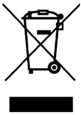
Symbol of a trash bin with crossed lines indicating no waste or discharge, and a solid black rectangle below (no text or labels)In the EU this symbol indicates that this product may not be disposed of as ordinary household waste. Old equipment contains valuable materials, suitable for recycling. These materials should be made suitable for reuse in order to prevent any adverse effects to health and the environment caused by unregulated waste collection. Therefore, please make sure that you bring old equipment to a designated collection point. Alternatively, contact the original supplier, who can make sure that as many of the components as possible can be recycled.
CE-statement
See page 114.
Remerciements
natural_image
Simple black-and-white diagram of a bowl with a lid and a label 'Zone 3' above it, no other text or symbols present.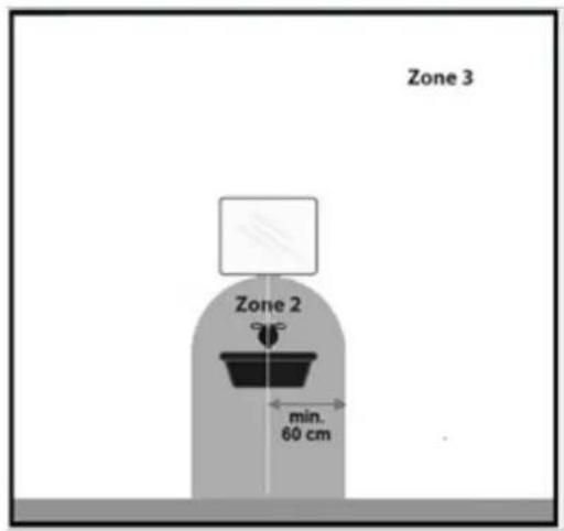

natural_image
Symbol of a trash bin crossed with a diagonal line, no text or numbers presentnatural_image
Simple black-and-white diagram of a bowl with a lid and a label 'Zone 3' above it, no other text or symbols present.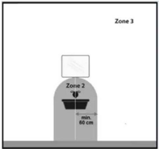
Varningar elvärmare
natural_image
Symbol of a trash bin crossed with no text or numbers, representing waste sorting or disposal (no text present)natural_image
Simple black-and-white diagram of a lamp with a base, labeled 'Zone 3' in the top right corner (no other text or symbols)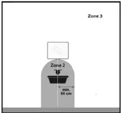
natural_image
Symbol of a trash bin with crossed lines indicating no waste or discharge, and a solid black rectangle below (no text or labels)natural_image
Simple black-and-white diagram of a lamp with a base, labeled 'Zone 3' in the top right corner (no other text or symbols)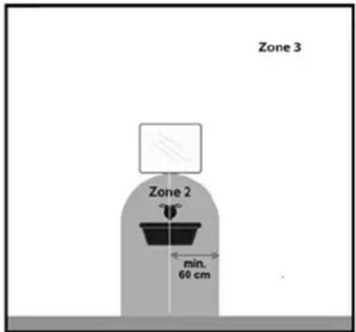
Upozornenia elektrický ohrievač
natural_image
Symbol of a trash bin crossed with no text or numbers, representing waste sorting or disposal (no text present)natural_image
Simple black-and-white diagram of a bowl with a stand and a label 'Zone 3' above it, no other text or symbols present.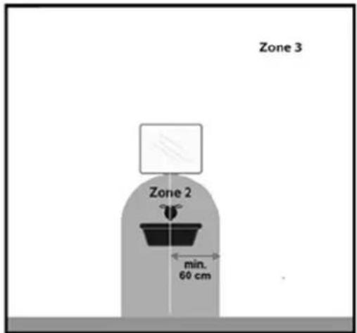
Avertismente radiatoare electrice
natural_image
Symbol of a trash bin crossed with two diagonal lines, no text or labels presentdeclares the following device in sole responsibility:
Product: bathroom heater
Brand name: EUROM
Model: Sani-Towel 500 and Sani-Towel 750
Item number: 352450, 352467 (Swiss plug) and 352474, 352481 (Swiss plug)
Complies with the following harmonization rules:
Low Voltage Directive: LVD 2014/35/EU
Electromagnetic compatibility Directive: EMC 2014/30/EU
Restriction of Hazardous Substances RoHS Directive: 2011/65/EU&(EU)2015/863
Framework Directive Ecodesign requirements: ERP 2009/125/EC
Regulation Ecodesign requirements for
Individual room heaters: (EU) 2015/1188
Regulation Ecodesign requirements Electricity
Consumption in standby and off state: 1275/2008/EC
Applied harmonized standards:
EN 60335-2-30:2009+A11
EN 60335-1:2012+A11+A13+A1+A14+A2
EN 60335-2-43:2003+A1+A2
EN 62233:2008
EN 55014-1:2017
EN 55014-2:2015
EN IEC 61000-3-2:2019
EN 61000-3-3:2013+A1
Genemuiden, 22-04-2020
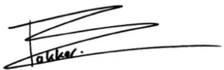
W.J. Bakker, alg. Dir.
EUROM
Kokosstraat 20
8281 JC Genemuiden
The Netherlands
info@eurom.nl
www.eurom.nl
220420


- Sani-Towel
- Dank
- Waarschuwingen elektrische kachels
- Is it possible to have an electric heater in the bathroom?
- Rule 1
- Rule 2
- Rule 3
- Zone 1 option 1: with shower cubicle / with bath-wall partition
- Zone 2 option 1: with shower cubicle / with bath-wall partition
- Zone 3- Other space
- Warning electric cables
- Safety warning - general
- Warnings device position
- Warnings - use
- Who can use the device?
- Warnings for maintenance
- Description
- Installation
- Using for the first time and operating
- Day/time setting
- Heating mode
- P1/P2/P3 setting heating program
- P1
- P2
- P3
- Timer function
- Open-window function
- Protections
- Overheating protection
- Cleaning and maintenance
- Removal
- CE-statement
- Remerciements
- Varningar elvärmare
- Upozornenia elektrický ohrievač
- Avertismente radiatoare electrice
- EUROM
Brand : Eurom
Model : Sani-Towel
Category : Oven