Capannina - Range hood Klarstein - Free user manual and instructions
Find the device manual for free Capannina Klarstein in PDF.


User questions about Capannina Klarstein
0 question about this device. Answer the ones you know or ask your own.
Ask a new question about this device
Download the instructions for your Range hood in PDF format for free! Find your manual Capannina - Klarstein and take your electronic device back in hand. On this page are published all the documents necessary for the use of your device. Capannina by Klarstein.
USER MANUAL Capannina Klarstein
text_image
QR code image containing encoded data, no visible human-readable textINHALTSVERZEICHNIS
natural_image
Simple line drawing of a rectangular block with a circular hole and an arrow, no text or symbols present.text_image
Technical diagram of a device with labeled parts and annotations in Chinese, showing internal components and directional arrows.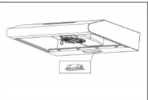
natural_image
Technical line drawing of a mechanical assembly with a component inside a housing (no text or symbols)text_image
Technical diagram showing two views of a computer with labeled components and instructional text in Chinese.INSTALLATION EINES AKTIVKOHLEFILTERS (OPTIONAL)
natural_image
Symbol of a trash bin crossed with a diagonal line, no text or numbers presentUnit 6 Riverside Business Centre
Brighton Road
Shoreham-by-Sea
BN43 6RE
United Kingdom
Dear Customer,
Congratulations on purchasing this device. Please read the following instructions carefully and follow them to prevent possible damages. We assume no liability for damage caused by disregard of the instructions and improper use. Scan the QR code to get access to the latest user manual and more product information.

text_image
QR code image containing encoded data, no visible human-readable textCONTENT
Safety Instructions 22
Product Overview 24
Dimensions 25
Ventilation Modes 26
Installation 27
Switches and Functions 30
Maintenance and Care 31
Installation of an Activated Carbon Filter (optional) 33
Troubleshooting 34
Notes on Environmental Protection 35
Product Data Sheet 36
Disposal Considerations 38
Manufacturer & Importer (UK) 38
TECHNICAL DATA
| Item number 10034859, 10034860, 10034861 |
| Power supply 220-240 V ~ 50 Hz |
| Noise level 52-60 dB |
| Note: You can also purchase an activated carbon filter for this cooker hood under item number 10035566. Please visit our website: www.hifi-tower.co.uk |
SAFETY INSTRUCTIONS
- Thank you for purchasing this cooker hood. Please read the instruction manual carefully before you use the cooker hood, and keep it in a safe place.
- The installation work must be carried out by a qualified electrician or competent person. Before you use the cooker hood, make sure that the voltage (V) and the frequency (Hz) indicated on the cooker hood are exactly the same as the voltage and the frequency in your home.
- The manufacturer and the agent will not bear any responsibility for the damage caused by inappropriate installation and usage.
• Children under the age of 8 must not use the cooker hood. - The appliance is not intended for commercial use, but only for household and similar environments.
- The cooker hood and its filter mesh should be cleaned regularly in order to keep it in good working order.
• Before cleaning, switch the power off at the main supply. - Clean the cooker hood according to the instruction manual and keep the cooker hood from the danger of burning.
• Prohibit putting the cooker hood by fire. - If the appliance does not function normally, contact the manufacturer or a specialist company.
- This device may be only used by children 8 years old or older and persons with limited physical, sensory and mental capabilities and / or lack of experience and knowledge, provided that they have been instructed in use of the device by a responsible person who understands the associated risks.
- If the supply cord is damaged, it must be replaced by the manufacturer, its service agent or similarly qualified persons in order to avoid a hazard.
- If the range hood is used at the same time as appliances burning gas or other fuels, the room must be adequately ventilated.
- Do not flambé under the range hood. Accessible parts may become hot when used with cooking appliances.
Important hints on installation
- The air must not be discharged into a flue that is used for exhausting fumes from appliances burning gas or other fuels (not applicable to appliances that only discharge the air back into the room).
• Regulations concerning the discharge of air have to be fulfilled.
Important notes about the extraction mode

WARNING
Risk of poisoning from exhaust gases sucked back. Never operate the device in extraction mode simultaneously with an open flue appliance when there is not adequate airflow guaranteed.
Open fl ue combustion equipment (for example, gas, oil, wood or coal-fi red heaters, tankless water heaters, water heaters) pulls combustion air from the room and runs it through an exhaust pipe or chimney to the outside. In the extraction mode, indoor air is removed from the kitchen and the adjacent rooms - without sufficient air intake this creates a vacuum. Toxic gases from the chimney or extraction fl ue can thereby be sucked back into the living spaces.
- Always ensure that a sufficient supply of fresh air is guaranteed and that the air can circulate.
- An air supply / extractor box alone does not ensure compliance with the limit value.
Safe operation is only possible when the negative pressure in the room where the appliance is located does not exceed 4 Pa (0.04 mbar). This can be achieved when the air required for combustion can flow through openings that are not closable, for example in doors, windows, in conjunction with an air supply / extractor box or through other technical measures. In any case, consult a qualified chimney sweep who can assess the entire ventilation of your house and propose appropriate measures for adequate ventilation.
If the hood is used exclusively in the recirculation mode, unrestricted operation is possible.
Important note on disassembly of the device
- Disassembly is similar to installation/assembly in reverse order.
• Take a second person to help you during disassembly to avoid injuries.
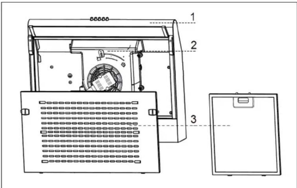
PRODUCT OVERVIEW
text_image
Technical diagram of a device interior with labeled components and internal structure| No. | Description Pc. No. Description Pc. | ||||
| 1 Air | duct assembly 1 3 Filter 1 | ||||
| 2 Ventilation knob 1 | |||||
| 5 Check valve 1 | No. Description Pc. | |
| 6 Exhaust valve 1 | ||
| 7 Screws 5*49 mm 4 | ||
| 8 Dowels 4 |
DIMENSIONS
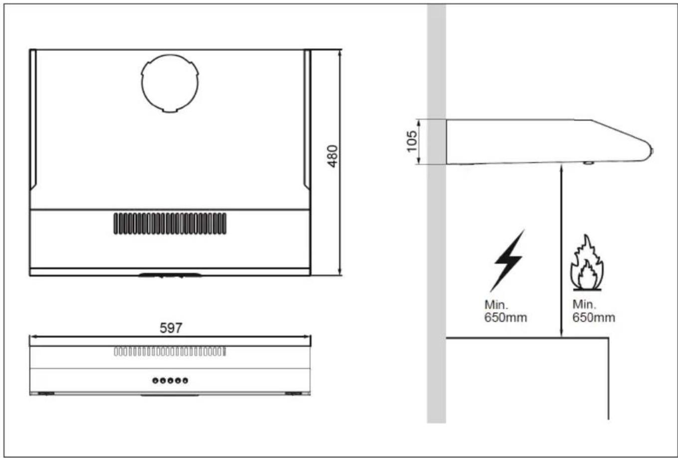
| X | 597 mm |
| F | 105 mm |
VENTILATION MODES
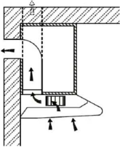 |  | |
| Exhaust air operation Recirculation mode | ||
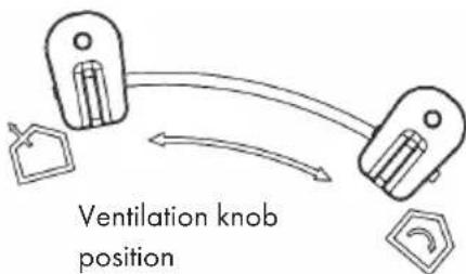 |  | Exhaust air operation: Turn the ventilation knob to this position. |
 | Recirculation mode: Turn the ventilation knob to this position. | |
natural_image
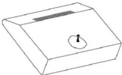
Simple line drawing of a rectangular block with a circular hole and an arrow, no text or symbols present.Note: If you opt for exhaust operation, install the check valve at the vent opening.
To install the check valve
| Hold the check valve firmly with your hands and align it with the vent opening. Insert the check valve and turn it until three angles of the valve are fixed. | 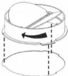 |
INSTALLATION
Preparations
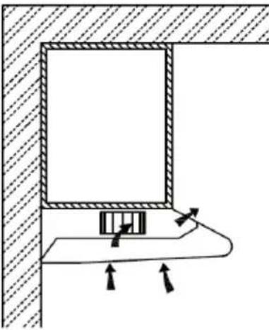
If you have a fume hood to the outside, you can install the fume hood as shown in the picture. The fume cupboard should have a diameter of at least 150 mm and be made of enamel, aluminium or a flexible, heat-resistant pipe.
Note: The hood should be placed 65-75 cm above the hob.

text_image
597 mm Min. 650mm Max. 750mmInstallation (Vent outside)
Note: When the range hood and appliance supplied with energy other than electricity are simultaneously in operation, the negative pressure in the room must be not exceed 4 Pa ( 4 × 10^-5 Bar).
Installation (Vent inside)
If you do not have an outlet to the outside, exhaust pipe is not required and the installation is similar to the one show in section "Installation (Vent outside)".
Important Information for the Installation of Exhaust Air Ducts
The following rules must be strictly observed to ensure optimum air extraction. Failure to follow these instructions will reduce performance and increase the noise level of the cooker hood.
- Lay the exhaust pipe as short and straight as possible.
- Do not use a smaller exhaust duct and do not confine it.
- If flexible ducts are used, the duct must always be mounted tightly in order to minimise pressure loss.
- All installation work may only be carried out by a qualified electrician or a qualified person.
- Do not connect the exhaust duct of the cooker hood to an existing ventilation system used for another appliance, such as a chimney.
- The angle of the exhaust pipe bend should not be less than 120^ . Align the pipe horizontally. Alternatively, the duct should go up from the starting point and be led to an outer wall.
- After installation, make sure that the cooker hood is level to prevent grease from accumulating on one side.
- Make sure that the exhaust duct selected for the installation complies with the relevant standards and is fire-resistant.
Installation under a wall cabinet
Drill a 130 mm diameter hole and four 3.5 mm diameter holes as shown below.
Note: If your cooker hood works in recirculation mode, it is not necessary to drill a hole!
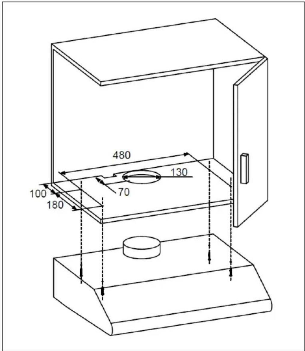
text_image
480 130 70 100 180Fasten the cooker hood to the wall cabinet using the 4 screws. Check the correct position of your fixings, position the cooker hood and tighten the screws.
Installation on the wall
1 Drill two 10 mm diameter holes in the wall at a distance of 538 mm, as shown in the picture. Make sure that the hood is directly above the hob.
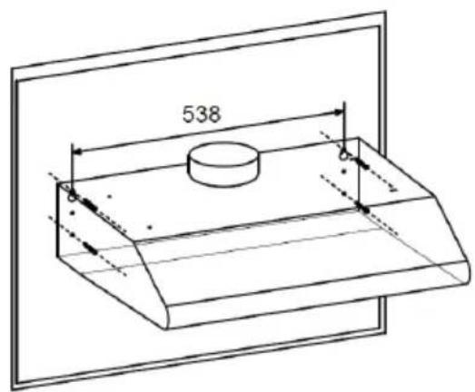
text_image
5382 Insert two of the supplied plastic plugs into the holes.
3 Insert two screws into both plastic plugs and allow the screws to protrude about 3 mm from the wall when tightening.
4 Hang the cooker hood on the two screws and mark the lower two screw positions.
5 Remove the cooker hood, drill the lower two screw holes and insert the remaining two plastic dowels.
6 Mount the hood on the upper screws, insert the lower screws and tighten all screws.
SWITCHES AND FUNCTIONS
 | Motor on/off |
 | Low speed |
 | Medium speed |
 | High speed |
 | Light on/off |
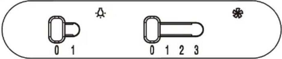 | ||
 | 0 Light off | |
| 1 Light on | ||
 | 0 Motor off | |
| 1 Low speed | ||
| 2 Medium speed | ||
| 3 High speed | ||
MAINTENANCE AND CARE
Replacing the light
1 Switch off the cooker hood and disconnect the cooker hood from the mains by pulling the mains plug or switching off the fuse.
2 Remove the grease filter.
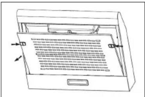
text_image
Technical diagram of a device with labeled parts and directional arrows indicating assembly or movement.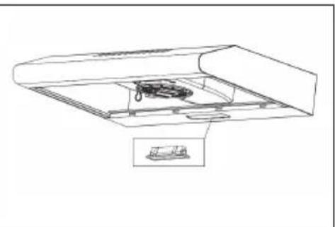
natural_image
Technical line drawing of a mechanical assembly with no visible text or symbols3 Remove the lamp by loosening its attachment from the hood body (this may require the application of pressure or force).
4 Disconnect the plug from the lamp.
5 Replace the lamp with a new one of the same type and ensure that the lamp is properly connected to the light cable.
6 Reconnect the power supply by plugging in the mains plug or by switching on the fuse.
Replacement lamp
| Max. power | Volatage Dimensions: 33,2 mm x 120 mm | ILCOS D code | |
| 1.5 W 220-240 V | 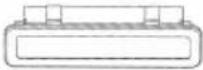 | DSH-1.5-S-33.2/120 | |
General instructions for cleaning
Turn off the cooker hood before cleaning and maintenance and unplug the appliance from the wall outlet. The exterior surfaces are susceptible to scratches and stains.
Therefore, do not use abrasive cleaners and wipe away any alkaline or acidic residue (lemon juice, vinegar) immediately after cleaning.
Stainless Steel Surfaces
The stainless steel must be cleaned regularly to ensure a long service life. Use stainless steel cleaner. Always wipe along the grain of the stainless steel to prevent scratching.
Control Panel
The control panel can be cleaned with a damp cloth and a mild dishwashing detergent. Before cleaning, make sure the cloth is clean and well wrung. Use a dry, soft cloth to remove excess moisture after cleaning.
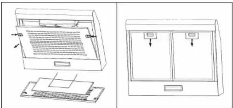
Monthly Cleaning for Grease Filter
Clean the filter every month can prevent any risk of fire. The filter collects grease, smoke and dust, so the filter is directly affecting the efficiency of the cooker hood. If not cleaned, the grease residue (potential flammable) will saturate on the filter.
- Remove the metal filter from the cooker hood and wash it with water and neutral liquid detergent so that it can soak.
- Rinse thoroughly with warm water and allow to dry.
- The metal filter can change colour after several washes. This is no reason for customer complaints or replacement of metal filters.
text_image
Technical diagram showing two views of a device with labeled components and instructional text in Chinese.INSTALLATION OF AN ACTIVATED CARBON FILTER (OPTIONAL)
Note: You can also purchase an activated carbon filter for this cooker hood under item number 10035566. Please visit our website: www.hifi-tower.co.uk
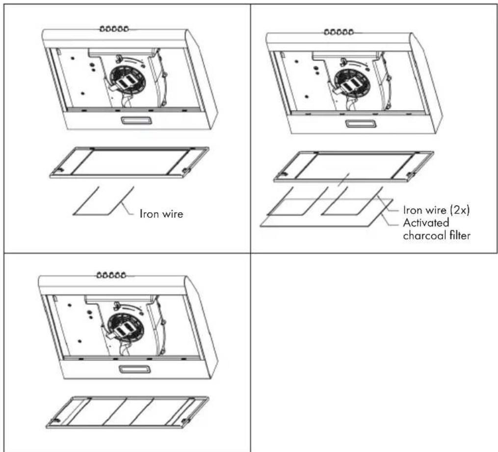
- Remove the grease filter and the iron wire.
- The activated carbon filter is located on the metal mesh and is fixed by two iron wires.
- Insert the activated carbon filter or replace the old activated carbon filter with a new one.
- Replace the iron wire and the grease filter.
Note: The activated carbon filter cannot be washed or recycled. It should be replaced after approximately 2-3 months of use.
text_image
00000 Iron wire 00000 Iron wire (2x) Activated charcoal filter 00000TROUBLESHOOTING
| Fault Possible Cause Solution | ||
| Light on, but motor does not work. | The leaf blocked. Get rid of the blocking. | |
| The capacitor damaged. Replace capacitor. | ||
| The motor jammed bearing damaged. | Replace motor. | |
| The internal with of motor off or a bad smell from the motor. | Replace motor. | |
| Light does not work, motor does not work. | Light damaged. Replace lights. | |
| Power cord looses. Connect the wires as per the electric diagram. | ||
| Shake of the body. The leaf | damaged and causes shaking. | Replace the leaf. |
| The motor is not tightly hanged. | Lock the motor tightly. | |
| The body is not tightly hanged. | Fixed the body tightly. | |
| Insufficient suction. The distance between the body and the gas top too long. | Readjust the distance. | |
| Too much ventilation from open doors or windows. Choose a new place and resemble the machine. | ||
NOTES ON ENVIRONMENTAL PROTECTION
- During cooking, make sure that there is sufficient air supply so that the cooker hood can operate efficiently and with low operating noise.
- Adjust the fan speed to the amount of steam produced during cooking. Use the intensive mode only when necessary. The lower the fan speed, the less energy is consumed.
- If large amounts of steam are produced during cooking, select a higher fan speed in good time. If the cooking steam has already dispersed in the kitchen, the cooker hood must be operated longer.
- Switch off the cooker hood when you no longer need it.
- Switch off the lighting when you no longer need it.
- Clean the filter at regular intervals and replace it if necessary to increase the effectiveness of the ventilation system and prevent fire hazards.
• Always put the lid on when cooking to reduce cooking steam and condensation.
PRODUCT DATA SHEET
Information according to Regulation (EU) No. 65/2014
Measurement and calculation methods according to EN 61591:1997+A1:2006+A2:2011+A11:2014+A12:2015
| Item number | 10034859, 10034860, 10034861 | ||
| Description Symbol Value Unit | |||
| Annual Energy Consumption AEC | hood | 42,9 kWh/Year | |
| Energy Efficiency class C | |||
| Fluid Dynamic Efficiency FDE | hood | 9,4 | |
| Fluid Dynamic Efficiency class E | |||
| Lighting Efficiency LE | hood | 35 Lux/W | |
| Lighting Efficiency class A | |||
| Grease Filtering Efficiency | GFBhood | 76,2 % | |
| Grease Filtering Efficiency class | C | ||
| air flow at minimum and maximum speed in normal use, intensive or boost excluded | 112,2/166,1 | m^3/h | |
| air flow at intensive or boost setting | - | m^3/h | |
| airborne acoustical A-weighted sound power emissions at minimum and maximum speed available in normal use | 52/60 | dB | |
| airborne acoustical A-weighted sound power emissions at intensive or boost setting | - | dB | |
| power consumption in off mode | Po | 0 | W |
| power consumption in standby mode | Ps | - | W |
| Contact details | Chal-Tec GmbH, Wallstraße 16, 10179, Berlin, Germany | ||
Information according to Regulation (EU) No. 66/2014
Measurement and calculation methods according to EN 61591:1997+A1:2006+A2:20
11+A11:2014+A12:2015
| Item number | 10034859, 10034860, 10034861 | ||
| Description Symbol Value Unit | |||
| Annual Energy Consumption AEC | hood | 42,9 kWh/Year | |
| Time increase factor f 1,7 | |||
| Fluid Dynamic Efficiency FDE | hood | 9,4 | |
| Energy Efficiency Index EEI | hood | 80,6 | |
| Measured air flow rate at best efficiency point | Q_BEP | 103,1 m^3/h | |
| Measured air pressure at best efficiency point | PBEP | 223 Pa | |
| Maximum air flow Q | max | 166,1 m^3/h | |
| Measured electric power input at best efficiency point | WBEP | 67,7 | W |
| Nominal power of the lighting system | W_L | 1,5 | W |
| Average illumination of the lighting system on the cooking surface | Emiddle | 45,8 | Lux |
| Measured power consumption in standby mode | P_o | - | W |
| Measured power consumption off mode | P_s | 0 | W |
| Sound power level | L_WA | 60 | dB |
| Contact details | Chal-Tec GmbH, Wallstraße 16, 10179, Berlin, Germany | ||
DISPOSAL CONSIDERATIONS
natural_image
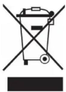
Symbol of a trash bin crossed with a diagonal line, no text or numbers presentIf there is a legal regulation for the disposal of electrical and electronic devices in your country, this symbol on the product or on the packaging indicates that this product must not be disposed of with household waste. Instead, it must be taken to a collection point for the recycling of electrical and electronic equipment. By disposing of it in accordance with the rules, you are protecting the environment and the health of your fellow human beings from negative consequences. For information about the recycling and disposal of this product, please contact your local authority or your household waste disposal service.
MANUFACTURER & IMPORTER (UK)
Manufacturer:
Chal-Tec GmbH, Wallstrasse 16, 10179 Berlin, Germany.
Importer for Great Britain:
Chal-Tec UK limited
Unit 6 Riverside Business Centre
Brighton Road
Shoreham-by-Sea
BN43 6RE
United Kingdom
Estimado cliente,
text_image
QR code image containing encoded data, no visible human-readable textÍNDICE DE CONTENIDOS
text_image
Technical diagram of a device with labeled components, showing internal structure and exterior viewnatural_image
Simple line drawing of a rectangular block with a circular hole and an arrow, no text or symbols present.text_image
Technical diagram of a device with labeled parts and directional arrows indicating assembly or movement.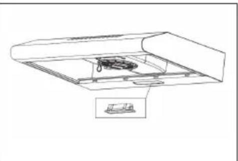
natural_image
Technical line drawing of a mechanical assembly with a component inside a housing (no text or symbols)text_image
Technical diagram showing two views of a device with labeled parts and annotations in Chinese.natural_image
Symbol of a trash bin crossed with a diagonal line, no text or numbers presentUnit 6 Riverside Business Centre
Brighton Road
Shoreham-by-Sea
BN43 6RE
United Kingdom
Chère cliente, cher client,
text_image
QR code image containing encoded data, no visible human-readable textSOMMAIRE
text_image
Technical diagram of a device with labeled components, showing internal structure and exterior viewnatural_image
Simple line drawing of a rectangular block with a circular hole and an arrow, no text or symbols present.text_image
Technical diagram of a device with labeled parts and directional arrows indicating assembly or movement.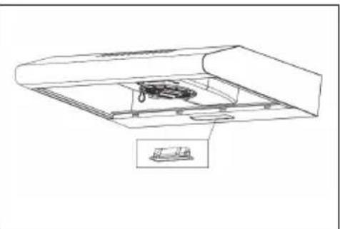
natural_image
Technical line drawing of a mechanical assembly with a component inside a housing (no text or symbols)text_image
Technical diagram showing two views of a computer with labeled parts and annotations in Chinese.INSTALLATION D'UN FILTRE À CHARBON ACTIF (FACULTATIF)
FICHE DE DONNÉES PRODUIT
natural_image
Symbol of a trash bin crossed with a diagonal line, no text or numbers presentUnit 6 Riverside Business Centre
Brighton Road
Shoreham-by-Sea
BN43 6RE
United Kingdom
Gentile cliente,
text_image
QR code image containing encoded data, no visible human-readable textINDICE
text_image
Technical diagram of a device with labeled components, showing internal structure and exterior viewnatural_image
Simple line drawing of a rectangular block with a circular hole and an arrow pointing to its center (no text or symbols)text_image
Technical diagram of a device with labeled parts and directional arrows indicating assembly or movement.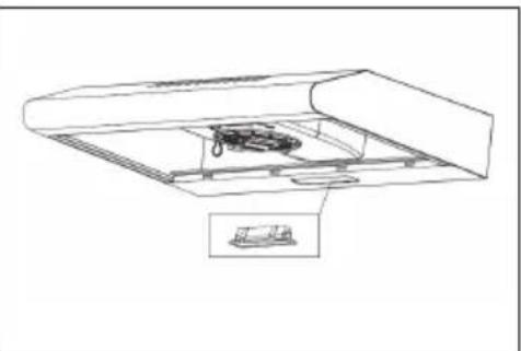
natural_image
Technical line drawing of a mechanical assembly with no visible text or symbolstext_image
Technical diagram showing two views of a device with labeled parts and annotations in Chinese.COME INSTALLARE UN FILTRO AI CARBONI ATTIVI (OPZIONALE)
natural_image
Symbol of a trash bin crossed with a diagonal line, no text or numbers presentPRODUTTORE E IMPORTATORE (UK)
Produttore:
Chal-Tec GmbH, Wallstraße 16, 10179 Berlino, Germania.
Unit 6 Riverside Business Centre
Brighton Road
Shoreham-by-Sea
BN43 6RE
United Kingdom

area
| Category | Value | |---|---| | 1 | 100 | | 2 | 100 | | 3 | 100 | | 4 | 100 | | 5 | 100 | | 6 | 100 | | 7 | 100 | | 8 | 100 | | 9 | 100 | | 10 | 100 | | 11 | 100 | | 12 | 100 | | 13 | 100 | | 14 | 100 | | 15 | 100 | | 16 | 100 | | 17 | 100 | | 18 | 100 | | 19 | 100 | | 20 | 100 | | 21 | 100 | | 22 | 100 | | 23 | 100 | | 24 | 100 | | 25 | 100 | | 26 | 100 | | 27 | 100 | | 28 | 100 | | 29 | 100 | | 30 | 100 | | 31 | 100 | | 32 | 100 | | 33 | 100 | | 34 | 100 | | 35 | 100 | | 36 | 100 | | 37 | 100 | | 38 | 100 | | 39 | 100 | | 40 | 100 | | 41 | 100 | | 42 | 100 | | 43 | 100 | | 44 | 100 | | 45 | 100 | | 46 | 100 | | 47 | 100 | | 48 | 100 | | 49 | 100 | | 50 | 100 | | 51 | 100 | | 52 | 100 | | 53 | 100 | | 54 | 100 | | 55 | 100 | | 56 | 100 | | 57 | 100 | | 58 | 100 | | 59 | 100 | | 60 | 100 | | 61 | 100 | | 62 | 100 | | 63 | 100 | | 64 | 100 | | 65 | 100 | | 66 | 100 | | 67 | 100 | | 68 | 100 | | 69 | 100 | | 70 | 100 | | 71 | 100 | | 72 | 100 | | 73 | 100 | | 74 | 100 | | 75 | 100 | | 76 | 100 | | 77 | 100 | | 78 | 100 | | 79 | 100 | | 80 | 100 | | 81 | 100 | | 82 | 100 | | 83 | 100 | | 84 | 100 | | 85 | 100 | | 86 | 100 | | 87 | 100 | | 88 | 100 | | 89 | 100 | | 90 | 100 | | 91 | 100 | | 92 | 100 | | 93 | 100 | | 94 | 100 | | 95 | 100 | | 96 | 100 | | 97 | 100 | | 98 | 100 | | 99 | 100 | | Note: The actual values in the 'Value' column are not provided in the code. I have used the label 'The Region' to represent the 'Region'. The values are estimated based on the provided code.