10030300 - Range hood Klarstein - Free user manual and instructions
Find the device manual for free 10030300 Klarstein in PDF.


User questions about 10030300 Klarstein
0 question about this device. Answer the ones you know or ask your own.
Ask a new question about this device
Download the instructions for your Range hood in PDF format for free! Find your manual 10030300 - Klarstein and take your electronic device back in hand. On this page are published all the documents necessary for the use of your device. 10030300 by Klarstein.
USER MANUAL 10030300 Klarstein
natural_image
Row of white kitchen and appliance icons including blender, kettle, oven, fan, fan with indicator lights, and microwave (no text or symbols)Dunstabzugshaube
10030272
10030275
10031905
10030273
10030276
10031906
10030274
10030300
10031910
natural_image
Diagram of a brick wall corner with a cylindrical component mounted on a base, showing structural details and an arrow indicating direction (no text or symbols present)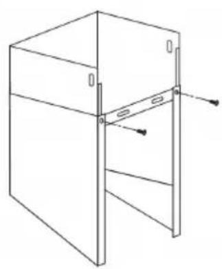
natural_image
Line drawing of a 3D rectangular box with internal structure and mounting points (no text or symbols)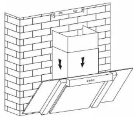
natural_image
Diagram of a brick wall with a box and two downward arrows indicating force or movement (no text or symbols present)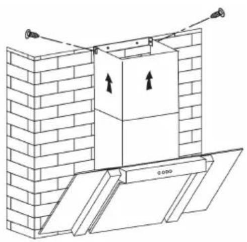
natural_image
Architectural diagram of a brick wall with an open door and upward arrows indicating forces or movement (no text or symbols)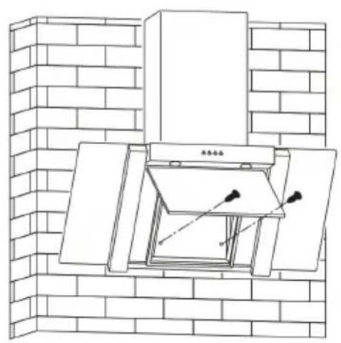
natural_image
Line drawing of a brick chimney with an open door and mounted fixtures (no text or symbols)natural_image
Isometric line drawing of a brick wall with embedded structural elements and dimension lines (no text or symbols)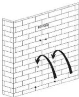
natural_image
Diagram of a brick wall with curved arrows indicating direction, no text or symbols present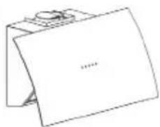
natural_image
Simple line drawing of a folded paper or envelope with a small circular object on top (no text or symbols)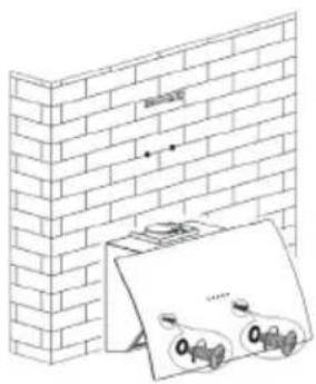
natural_image
Illustration of a brick wall with a magnified inset showing a magnified view of a small object (no text or symbols present)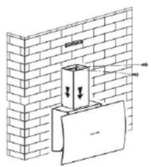
text_image
Diagram showing a brick wall with a container and a paper strip, annotated with arrows indicating downward forces or movement.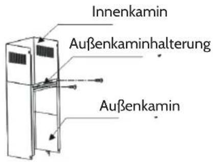
natural_image
Technical line drawing of a brick wall and a vertical stack with an upward arrow, showing structural components (no text or symbols)natural_image
Isometric line drawing of a brick wall with two small arrows pointing to specific edges (no text or symbols)Bild 2
natural_image
Diagram of a brick wall with a double-headed pipe opening, showing airflow direction (no text or symbols)Bild 3
Bedienung
text_image
Stop Low Mid High Lighttext_image
Diagram of a boat hull with numbered parts and directional arrows indicating flow or movementtext_image
Diagram showing a boat hull with numbered parts and directional arrows indicating flow or movement.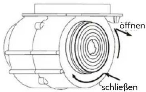
natural_image
Symbol of a trash bin with crossed lines indicating no waste or discharge (no text or labels)Congratulations on purchasing this equipment. Please read this manual carefully and take care of the following hints on installation and use to avoid technical damages. Any failure caused by ignoring the items and cautions mentioned in the operation and installation instructions are not covered by our warranty and any liability.
Contents
Safety Instructions. 17
Installation 18
Operation 24
Cleaning and Maintenance 27
Troubleshooting 28
Declaration of Conformity 29
Declaration of Conformity 29
Safety Instructions
- These instructions are for your safety. Please read through them thoroughly prior to installation and retain them for future reference.
Children in the household
- Young children should be kept away. Care should be taken to avoid touching the appliance.
- This appliance can be used by children aged from 8 years and above and persons with reduced physical, sensory or mental capabilities or lack of experience and knowledge if they have been given supervision or instruction concerning use of the appliance in a safe way and understand the hazards involved. Children shall not play with the appliance. Cleaning and user maintenance shall not be made by children unless they are older than 8 and supervised.
- Keep the appliance and its cord out of reach of children less than 8 years.
General
• The appliance is for domestic use only.
- Accessible parts may become hot during use.
- Do not flame under the range hood.
- Regularly check the power plug and power cord for damage. If the supply cord is damaged, it must be replaced by the manufacturer, its service agent or similarly qualified persons in order to avoid a hazard.
- Make sure that the power cord is not caught under or in the appliance and avoid damage to the power cable.
- Do not install the appliance outdoors in a damp place or in an area which may be prone to water leaks such as under or near a sink unit. In the event of a water leak allow the machine to dry naturally.
Cleaning
- Do not use flammable sprays in close vicinity to the appliance.
- Please dispose of the packing material carefully.
- We also recommend that great care be taken during use and cleaning. Read the cleaning and maintenance sections for this appliance carefully.
- A steam cleaner is not to be used.
Installation
- All installation work must be carried out by a competent person or qualified electrician.
- This appliance must be installed correctly by a suitably qualified person, strictly following the manufacturer's instructions.
- Means for disconnection must be incorporated in the fixed wiring in accordance with the wiring rules. An all-pole disconnection switch having a contact separation of at least 3 mm in all poles should be connected in fixed wiring
- Consult local regulations regarding fumes outlets. Do not connect the hood to a fume, ventilation or hot air duct. Confirm that room ventilation is appropriate with the local authorities. Make sure the maximum air extraction flow rate for the appliances in the room does not exceed 4 Pa (0.04 mbar). The room must have adequate ventilation if an extractor hood is used simultaneously with appliances that run on gas or other fuels. The air must not be discharged into a flue that is used for exhausting fumes from appliances
burning gas or other fuels. Regulations regarding air extraction must be complied with.
- Before connecting the hood: switch off the electricity supply and check that the supplied voltage and frequency coincide with that indicated on the appliance nameplate.
- The hood may stop working during an electrostatic discharge (e.g. lightning). This involves no risk of damage. Switch off the electricity supply to the hood and reconnect after one minute.
- Do not use the hood if it shows signs of damage or imperfection. Contact customer services.
Installation
Models without glass (10030272)
-
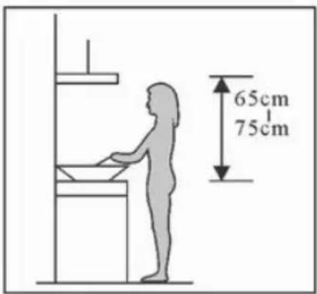
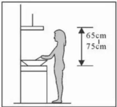
The cooker hood should be placed at a distance of 65-75cm (26-30inch) from the cooking surface for the best effect. See Pic 1.
-
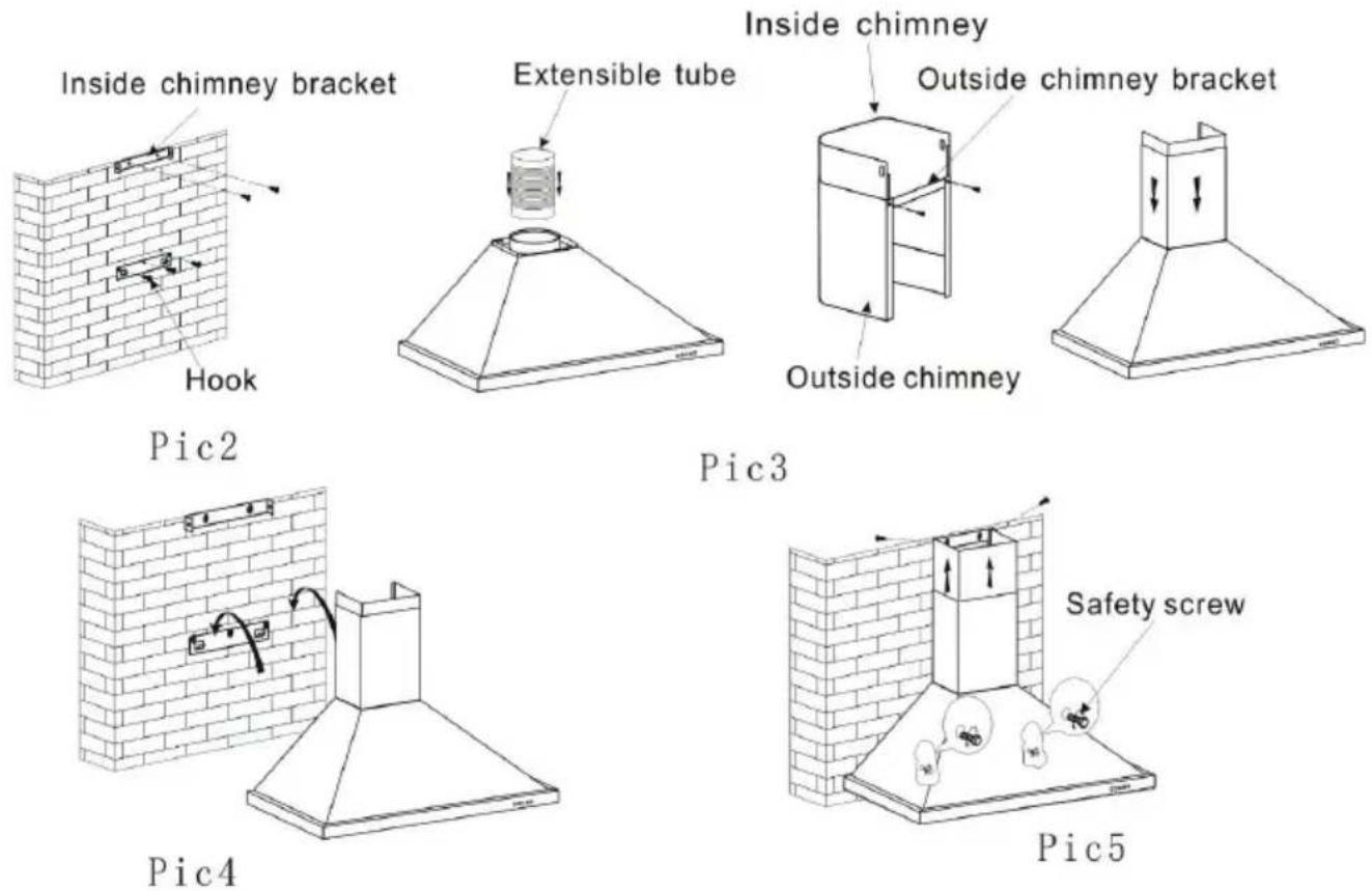
Install the hook on a suitable place once the installation height is fixed, and keep it in line. The fixed position of the inside chimney bracket is the place of chimney.
-
Fix the outside chimney bracket on the outside chimney, and be sure that the inside chimney can be adjusted the height in it freely as well as fixing the extensible pipe. Afterwards, install the extensible pipe and chimney on the cooker hood. See Pic 3.
-
Put the cooker hood on the hook. See Pic 4.
-
Adjust the height of the inside chimney to the position of the inside chimney bracket and fix on it by screw, after adjusting the position, fix the body with safety screw. See Pic 5.
Note: The two safety vents are positioned on the back casing, with diameter of 6mm.
text_image
65cm 75cmPic1
For models with glass (10030273)
- The cooker hood should be placed at a distance of 65-75cm (26-30inch) from the cooking surface for the best effect. See Pic 1.
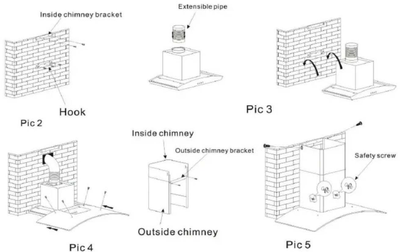
- Install the hook on a suitable place once the installation height is fixed, and keep it in line. The fixed position of the inside chimney bracket is the place of chimney.
- Fix the extensible pipe according to the lead direction and way, and then put the cooker hood on the hook. See pic 3.
- Put the glass according to the lead direction and way on the cooker hood, and then use the screws to fix the glass, also lead the extensible pipe outside of the room, meanwhile adjust the height of the inside chimney to the position of the inside chimney bracket and fix on it by screw, here should be sure the inside chimney can be flexed freely. See Pic 4.
- Put the two chimneys together onto the cooker hood body, meanwhile adjust the height of the inside chimney into the suitable height, and fix the inside chimney to the inside chimney bracket by screw. Finally, fix the body with safety screw. See Pic 5.
Note: The two safety vents are positioned on the back casing, with diameter of 6mm.
text_image
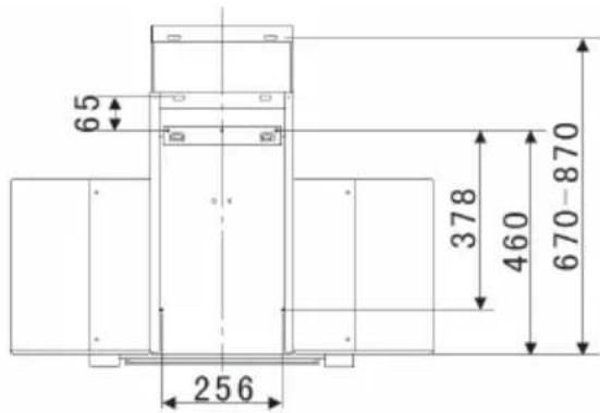
65 256 378 460 670-870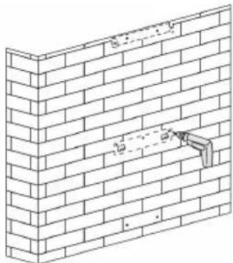
natural_image
Isometric line drawing of a brick wall with a pipe inserted, showing construction details (no text or symbols)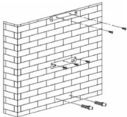
natural_image
Isometric line drawing of a brick wall with embedded fixtures and structural elements (no text or symbols)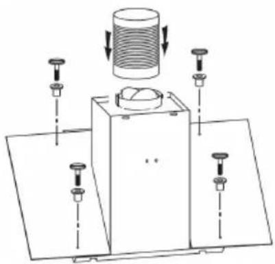
natural_image
Technical diagram of a mechanical assembly with a cylindrical component and multiple base plates (no text or symbols)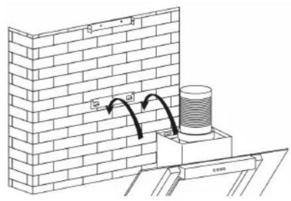
natural_image
Diagram of a brick wall corner with a cylindrical component mounted on a base, showing structural details and an arrow indicating direction (no text or symbols present)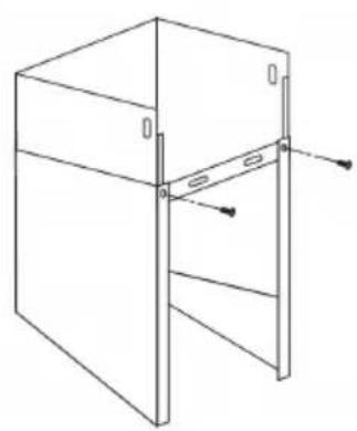
natural_image
Technical line drawing of a cabinet or enclosure with mounting holes and structural supports (no text or symbols)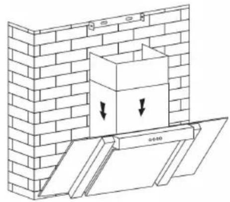
natural_image
Diagram of a brick wall with a box and two downward arrows indicating force or movement (no text or symbols present)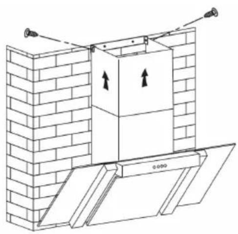
natural_image
Architectural line drawing of a brick wall with an open door and upward arrows indicating direction (no text or symbols)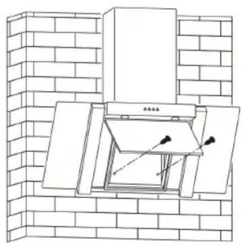
natural_image
Line drawing of a brick chimney with an open door and mounted equipment (no text or symbols)- Connect the plug into the power.
- Press the button "Stop", the motor is stopped then
- Press the button "Low", the motor is running at low speed. Press the button "Mid", the motor is running at medium speed. Press the button "High", the motor is running at high speed.
- Press the button "Light", both lights start shining. Press the button again; the lights are switched off then.
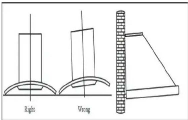
text_image
Right WrongFor the model 10031905
- The cooker hood should be placed at a distance of 65-75cm (26-30inch) from the cooking surface for the best effect.
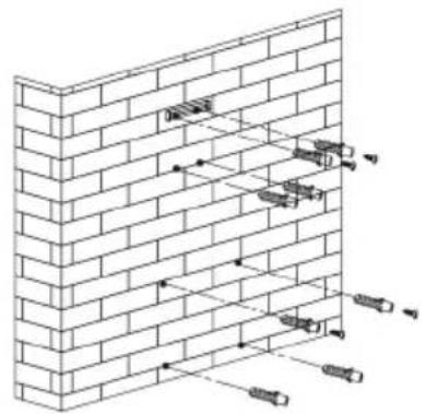
- Install the hanging screw on a suitable place once the installation height is fixed, and keep it in line. The fixed position of the inside chimney bracket is the place of chimney. Also install the safety hole in the wall. Total drill 8 holes and insert the Wall plug. See Pic 2.
- Hang the cooker hood on wall, See Pic 3.
- Use 2 screws (4*30mm) to fix the safety locks in the cooker hood on the wall. See Pic 4.
- Put the inner chimney inside the outer chimney. Install the outer chimney bracket on the outer chimney by two screws (4mm x 8mm). See Pic 5.
- Put the installed chimneys on the cooker hoods. Fix the outer chimney to the cooker hood by 2 screws (4*8mm), then fix the outer chimney bracket to the wall by using 2 (4mm x 40mm) screws and wall plugs. See Pic 6.
- Lift up inner chimney on the wall. Fix the inner chimney to the inside chimney bracket by using 2 screws (4mm x 8mm). The same operation to the outer chimney. See Pic 7.
natural_image
Isometric line drawing of a brick wall with embedded fixtures and structural elements (no text or symbols)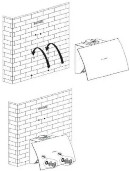
text_image
Diagram illustrating brick wall corner installation with directional arrows and labeled components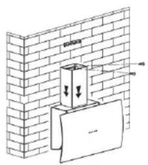
text_image
Diagram showing a brick wall with a container and a paper strip, annotated with arrows indicating downward forces or movement.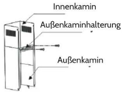
natural_image
Technical line drawing of a brick wall and a vertical stack with an upward arrow, showing structural components (no text or symbols)- The cooker hood should be placed at a distance of 65-75cm (26-30inch) from the cooking surface for the best effect. See Pic 1.
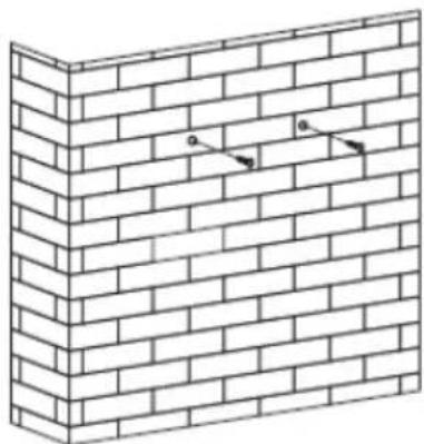
- Install the hanging screw on a suitable place once the installation height is fixed, drill 2 holes and insert the Wall plug put 2pcs screws(ST4*30mm) into wall plug, and keep it in line. See Pic 2.
- Hang the cooker hood on the screws,
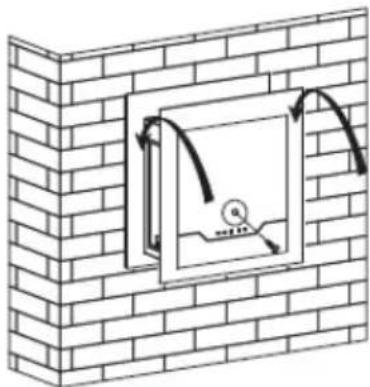
- Use 2 screws (S4*30mm) to fix the safety locks in the cooker hood on the wall. See Pic 3
text_image
65cm 75cmBild 1
natural_image
Isometric line drawing of a brick wall with two small arrows pointing to specific edges (no text or symbols)Bild 2
natural_image
Diagram of a brick wall with a double-headed pipe opening, showing airflow direction (no text or symbols)Bild 3
Operation
Control panel for Item 10030272, 10031905, 10031910




| After connecting power to power, the control panel will be lightet. The light will shut off automatically after 30 seconds if without any operation. | ||
 | On/Off Switches | the ventilation on and off. |
 | Light Switches the light on and off. | |
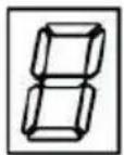
 | Ventilation speed | The motor has the low speed, mid. speed and high speed.When the hood is working with low speed,LED display will show 1.Press the botton, then the hood will transfer to the mid speed for working; the LED will show 2 , press the speed button again , the hood will transfer to the high speed for working immediately. And so on.. |
 | Timer | This is a 9 minute timer. When the hood is working, press this button to set a time for motor operation.press the botton ,LED display will be shown 9.8.7.6 until 0, When LCD shows 0, After 30 seconds without operation; the backlight will disappear.Please note the Lamp is not under control of timer. |
Control panel for Item 10030273, 10030274, 10030275, 10031906
text_image
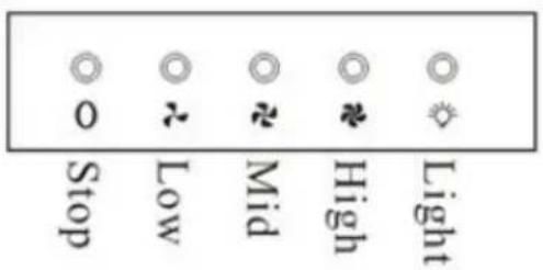
Stop Low Mid High Light| O | OFF Switches the ventilation off. | |
| [7802] | Low Speed button | It is used for Ventilation on the kitchen. It is suitable for simmering and cooking which do not make much steam. Press again to stop the motor. |
| [7A0A] | Medium Speed button | Airflow speed is ideally for ventilation in standard cooking operation. Press again to stop the motor. |
| [ATC2] | High Speed button | When high density of smoke or steam produced, press high-speed button for highest effective ventilation. Press again to stop the motor. |
 | Light button Switching on and off the light. | |
| Power on: After you have connected the cooker hood to the mains supply the backlight will turn on. The backlight will turn off after 5s without any operation and hood will enter stand-by mode.When pressing a key it is lit. | ||
 | Light Switches light on and off. | |
 | Low speed | Push the low button, the indicating light will be lit, and the motor runs at low speed. Push it again and the motor will stop. |
 | Mid speed | Push the middle button, the indicating light will be lit, and the motor runs at mid speed. Push it again and the motor will stop. |
 | High speed | Push the high button, the indicating light will be lit, and motor runs on high speed. Push it again and the motor will stop. |
 | Timer | Whilst the cooker hood is in use, if you press the timer button once the hood will run for 5 minutes and then cut off. |
Cleaning and Maintenance
The cleaning of the carbon grease filter mesh
The filter mesh is made of high-density stainless steel. Please do not use the corrosive detergent on it. Keeping this filter clean will keep the appliance running correctly. Please strictly follow the guidelines below.
Method 1:
Put the mesh into 40-50 c clean water, pour on detergent, and soak for 2-3 mins. Wear gloves and clean with a soft brush. Please do not apply too much pressure, as the mesh is delicate and will damage easy.
Method 2:
If instructed to do so, it can be put into a dishwasher, set the temperature at around 60 degrees.
text_image
Diagram of a boat hull with numbered components and directional arrows indicating flow or movementCleaning the cooker hood
- To protect the main body from corrosion over a long period of time, the cooker hood should be cleaned with hot water plus non corrosive detergent every two months.
- Please do not use abrasive detergent for it will damage the body.
- Keep the motor and other spare parts free from water, as this will cause damage to the appliance.
- Before cleaning the appliance please remember to cut off power
- The carbon filter shouldn't be exposed to heat.
- Please don't tear open the fixed bar around the carbon filter.
- If the plug or cord is damaged, please replace it with special soft cord
Installation of the carbon filter
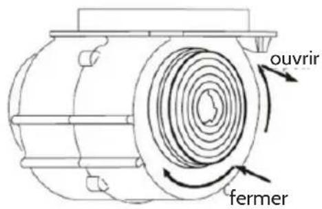
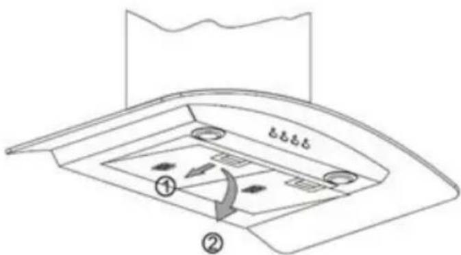
Remove the grease filters
The charcoal filters are located at both end of the motor. Turn the charcoal filters until they are unscrewed.
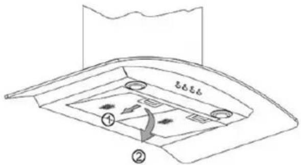
text_image
① ②
text_image
Open CloseThe carbon filters should be replaced every 3 - 6 months or if they show signs of damage.
Troubleshooting
| Fault Cause Solution | ||
| Light on, but fan does not work | The fan blade is jammed. Switch of the unit and repair by qualified service personnel only. | |
| The motor is damaged. | ||
| Both light and fan do not work | Light bulb burn Replace the bulb with correct rating. | |
| Power cord looses. Plug in to the power supply again. | ||
| Serious Vibration of the unit | The fan blade is damaged. Switch of the unit and repair by qualified service personnel only. | |
| The fan motor is not fixed tightly. | Switch of the unit and repair by qualified service personnel only. | |
| The unit is not hung properly on the bracket. | Take down the unit and check whether the bracket is in proper location. | |
| Suction performance not good | Too long distance between the unit and the cooking plane. | Readjust the distance to 65-75 cm. |
Declaration of Conformity
natural_image
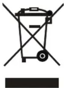
Symbol of a trash bin with crossed lines indicating no waste or discharge (no text or labels)According to the European waste regulation 2012/19/EU this symbol on the product or on its packaging indicates that this product may not be treated as household waste. Instead it should be taken to the appropriate collection point for the recycling of electrical and electronic equipment. By ensuring this product is disposed of correctly, you will help prevent potential negative consequences for the environment and human health, which could otherwise be caused by inappropriate waste handling of this product. For more detailed information about recycling of this product, please contact your local council or your household waste disposal service.
Declaration of Conformity
CE
Producer: Chal-Tec GmbH, Wallstraße 16, 10179 Berlin. Germany
This product is conform to the following European Directives:
2014/30/EU (EM)
2014/35/EU (LVD)
2009/125/EG (ErP)
natural_image
Diagram showing a brick wall with a chimney and a base structure, no text or symbols present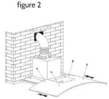
text_image
figure 2figure 4
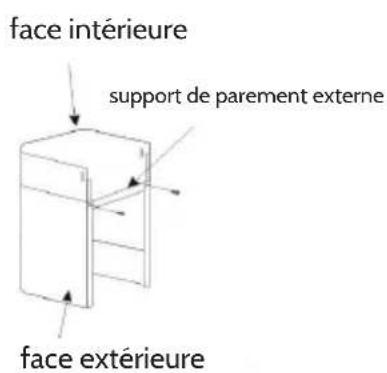
natural_image
Isometric line drawing of a brick wall with a pipe or pipe fitting inserted (no text or symbols)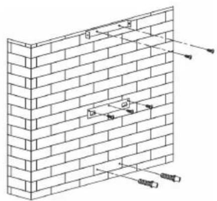
natural_image
Isometric line drawing of a brick wall with embedded fixtures and support beams (no text or symbols)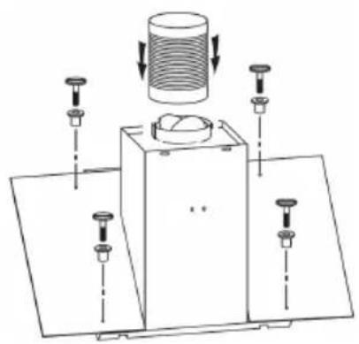
natural_image
Technical diagram of a mechanical assembly with a cylindrical component and multiple base plates (no text or symbols)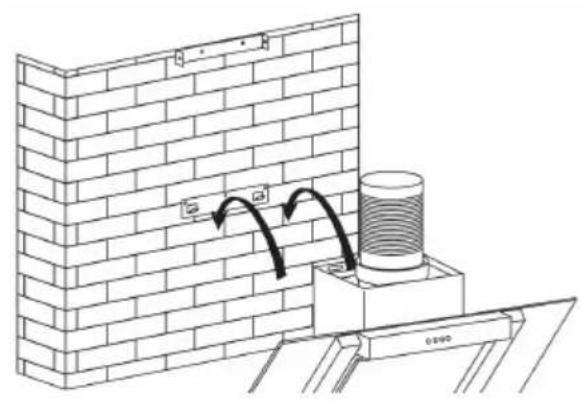
natural_image
Diagram of a brick wall corner with a cylindrical component mounted on a base, showing structural details and an arrow indicating direction (no text or symbols present)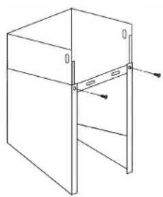
natural_image
Technical line drawing of a cabinet or enclosure with mounting holes and structural beams (no text or symbols)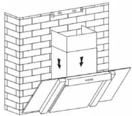
natural_image
Diagram of a brick wall with a box and two downward arrows indicating force or movement (no text or symbols present)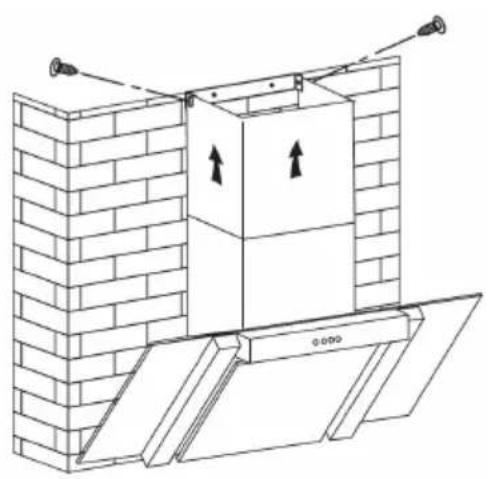
natural_image
Architectural diagram of a brick wall with an open door and ceiling-mounted fixtures (no text or symbols)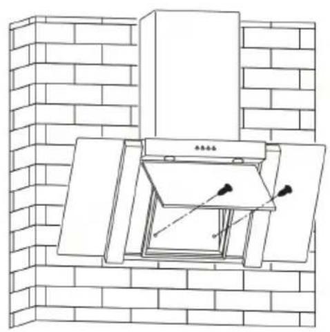
natural_image
Line drawing of a brick chimney with an open door and mounted fixtures (no text or symbols)text_image
correct incorrectnatural_image
Isometric line drawing of a brick wall with embedded structural elements and dimension lines (no text or symbols)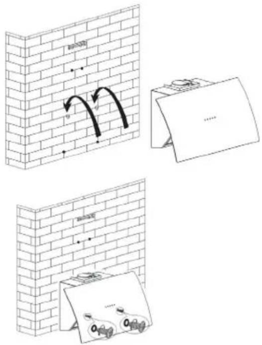
text_image
Diagram illustrating brick wall corner installation with directional arrows and labeled components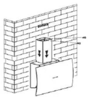
text_image
Diagram showing a brick wall with a container and a paper strip, annotated with arrows indicating downward forces or movement.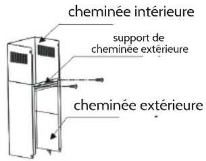
natural_image
Technical line drawing of a brick wall and a vertical stack with an upward arrow, showing structural components (no text or symbols)natural_image
Diagram of a brick wall with two arrows pointing to specific edges (no text or symbols)figure 2
natural_image
Diagram of a brick wall with a double-headed pipe opening, showing airflow or force direction (no text or symbols)figure 3
Fonctionnement
text_image
Stop Low Mid High Lighttext_image
Diagram of a boat hull with numbered components and directional arrows indicating flow or movementNettoyage de la hotte aspirante
text_image
Diagram of a boat hull with numbered parts and directional arrows indicating flow or movement