
WS 460 - Concrete saw HUSQVARNA - Free user manual and instructions
Find the device manual for free WS 460 HUSQVARNA in PDF.
| Product type | Wall concrete saw |
| Brand | HUSQVARNA |
| Model | WS 460 |
| Weight of sawing unit | 28 kg (62 lbs) |
| Weight of blade flange hub | 3.8 kg (8.3 lbs) |
| Weight of blade guard | 15 kg (33 lbs) |
| Weight of Series 400 rail (1.2 m) | 12.2 kg (26.9 lbs) |
| Max hydraulic oil flow | 102 l/min (27 gpm) |
| Max pressure | 206 bar (3000 psi) |
| Feed drive | Hydraulic |
| Max cutting depth (600 mm blade) | 230 mm |
| Max cutting depth (800 mm blade) | 330 mm |
| Max cutting depth (1000 mm blade) | 430 mm |
| Max cutting depth (1200 mm blade) | 530 mm |
| Spindle speed (600-800 mm blade) | 1100-1500 rpm |
| Spindle speed (1000-1200 mm blade) | 800-1000 rpm |
| Measured sound power level | 117.8 dB(A) |
| Sound pressure level (user) | 100.3 dB(A) |
| Intended use | Cutting concrete, brick and stone-based materials |
| Safety | Mandatory protective equipment (helmet, ear protectors, goggles, mask) |
| Maintenance | Oil change of saw arm, gear lubrication, cleaning after each use |
| Compatible power pack | PP 3300, PP 2525, PP 2325 |
Frequently Asked Questions - WS 460 HUSQVARNA
User questions about WS 460 HUSQVARNA
0 question about this device. Answer the ones you know or ask your own.
Ask a new question about this device
Download the instructions for your Concrete saw in PDF format for free! Find your manual WS 460 - HUSQVARNA and take your electronic device back in hand. On this page are published all the documents necessary for the use of your device. WS 460 by HUSQVARNA.
USER MANUAL WS 460 HUSQVARNA
natural_image
Icon of an open book inside a circle (no text or symbols)
Operator's manual
Please read the operator's manual carefully and make sure you understand the instructions before using the machine.

natural_image
Simple line drawing of a mechanical device inside a circle (no text or symbols)GB ES DE FR
Symbols on the machine:
WARNING! The machine can be a dangerous tool if used incorrectly or carelessly, which can cause serious or fatal injury to the operator or others.
Please read the operator's manual carefully and make sure you understand the instructions before using the machine.
Always wear:
• Approved protective helmet
• Approved hearing protection
• Protective goggles or a visor
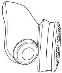
- Breathing mask
This product is in accordance with applicable EC directives.

natural_image
Three black-and-white icons: warning triangle, open book, and face mask (no text or symbols)
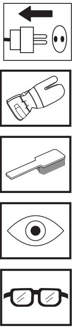
Symbols in the operator's manual:
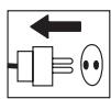
Inspection and/or maintenance should be carried out with the motor switched off and the plug to the hydraulic unit disconnected.
Always wear approved protective gloves.
Regular cleaning is required.
Visual check.
Protective goggles or a visor must be worn.
Contents
KEY TO SYMBOLS
Symbols on the machine: 2
Symbols in the operator's manual: 2
CONTENTS
Contents 3
WHAT IS WHAT?
What is what on the wall saw? 4
SAFETY INSTRUCTIONS
Steps before using a new wall saw 5
Personal protective equipment 5
General safety precautions 6
General working instructions 6
Basic working techniques 7
PRESENTATION
WS 460 8
ASSEMBLY
Mount wall mountings and rail 9
Mount the saw carriage and saw 10
Fit the blade 11
Flush cutting 11
Fit the blade guard 12
Connect the hydraulic unit 12
STARTING AND STOPPING
Before starting 13
Starting 13
Stopping 13
Dismantling the saw 13
Cleaning 13
SETTINGS AND ADJUSTMENTS
Track 360 14
Track 400 series 15
MAINTENANCE
Maintenance 16
Repairs 16
Daily maintenance 16
TECHNICAL DATA
WS 460 17
EC-declaration of conformity 18
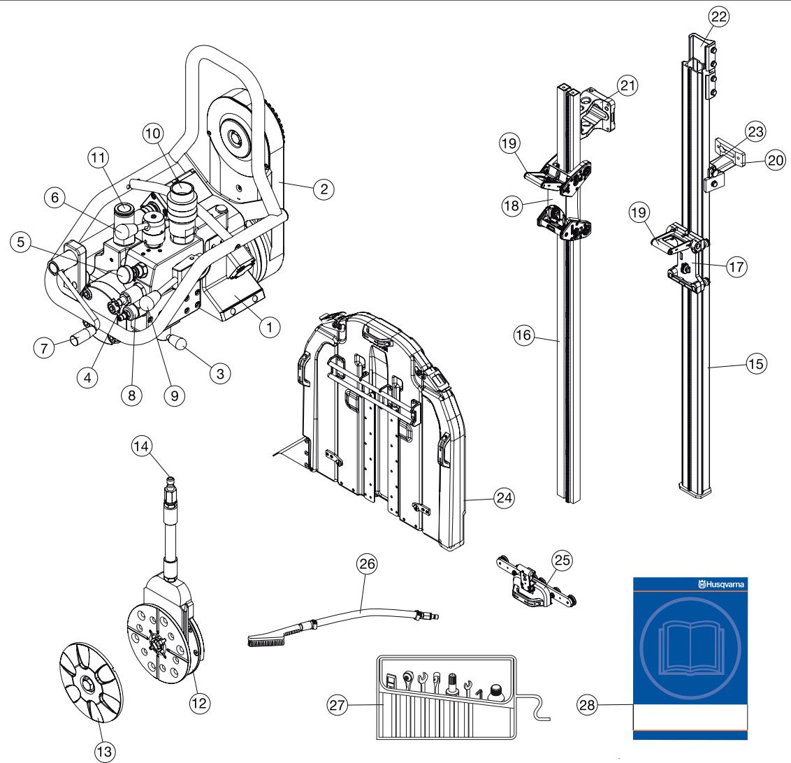
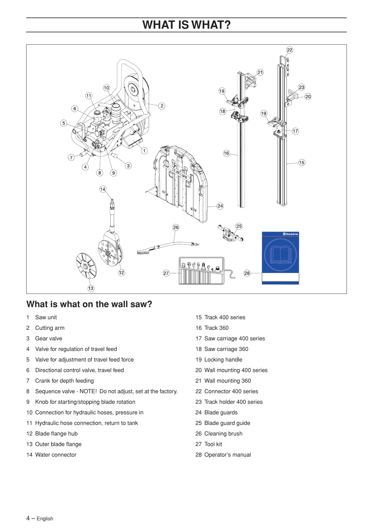
What is what on the wall saw?
1 Saw unit
2 Cutting arm
3 Gear valve
4 Valve for regulation of travel feed
5 Valve for adjustment of travel feed force
6 Directional control valve, travel feed
7 Crank for depth feeding
8 Sequence valve - NOTE! Do not adjust, set at the factory.
9 Knob for starting/stopping blade rotation
10 Connection for hydraulic hoses, pressure in
11 Hydraulic hose connection, return to tank
12 Blade flange hub
13 Outer blade flange
14 Water connector
15 Track 400 series
16 Track 360
17 Saw carriage 400 series
18 Saw carriage 360
19 Locking handle
20 Wall mounting 400 series
21 Wall mounting 360
22 Connector 400 series
23 Track holder 400 series
24 Blade guards
25 Blade guard guide
26 Cleaning brush
27 Tool kit
28 Operator's manual
Steps before using a new wall saw
- Please read the operator's manual carefully and make sure you understand the instructions before using the machine.
- This machine is designed for and intended for sawing concrete, brick and different stone materials. All other use is improper.
- This machine is intended for use together with a Husqvarna PP 3300, Husqvarna PP 2525 and Husqvarna PP 2325. If the saw is used with another hydraulic unit, the unit must be compatible with the conditions required by the saw.
- The machine is intended for use in industrial applications by experienced operators.
- Please read the operator's manual supplied with the hydraulic unit before using the machine.
- The machine can cause serious personal injury. Read the safety instructions carefully. Learn how to use the machine.
Always use common sense
It is not possible to cover every conceivable situation you can face. Always exercise care and use your common sense. Avoid all situations which you consider to be beyond your capability. If you still feel uncertain about operating procedures after reading these instructions, you should consult an expert before continuing.
Do not hesitate to contact your dealer if you have any more questions about the use of the machine. We will willingly be of service and provide you with advice as well as help you to use your machine both efficiently and safely.
Let your Husqvarna dealer regularly check the machine and make essential adjustments and repairs.
All information and all data in the Operator's Manual were applicable at the time the Operator's Manual was sent to print.

WARNING! Under no circumstances should you modify the original design of the machine without approval from the manufacturer. Always use original spare parts. Unauthorised modifications and/or accessories may lead to serious injury or death to the user or others.

WARNING! Use of products which cut, grind, drill, sand or shape material can generate dust and vapors which may contain harmful chemicals. Know the nature of the material being worked on and wear appropriate dust mask or respirator protection.
Personal protective equipment

WARNING! You must use approved personal protective equipment whenever you use the machine. Personal protective equipment cannot eliminate the risk of injury but it will reduce the degree of injury if an accident does happen. Ask your dealer for help in choosing the right equipment.
- Protective helmet
- Hearing protection
• Protective goggles or a visor
- Breathing mask
natural_image
Line drawing of a mechanical component with a flanged handle and circular base (no text or symbols)• Heavy-duty, firm grip gloves.
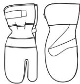
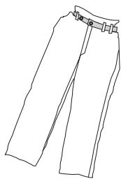
- Tight-fitting, heavy-duty and comfortable clothing that permits full freedom of movement.
natural_image
Line drawing of a pair of trousers with a belt buckle (no text or symbols)• Boots with steel toe-caps and non-slip sole.
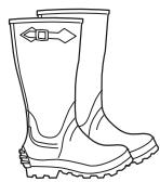
• Always have a first aid kit nearby.

General safety precautions
Do not use the machine without first reading and understanding the contents of this Operator's Manual.

WARNING! There is always a risk of crush injuries when working with products containing moving parts. Wear protective gloves to avoid body injuries.
- Never use the machine if you are tired, if you have drunk alcohol, or if you are taking medication that could affect your vision, your judgement or your co-ordination.
- Wear personal protective equipment. See instructions under the heading Personal protective equipment.
- Keep all parts in good working order and ensure that all fixtures are properly tightened.
- Never use a machine that is faulty. Carry out the checks, maintenance and service instructions described in this manual. Some maintenance and service measures must be carried out by trained and qualified specialists. See instructions under the heading Maintenance.
- Do not modify safety equipment. Check regularly that they function as they should. The machine must not be run with defective or disassembled safety equipment.
- Never allow anyone else to use the machine without first ensuring that they have understood the contents of the operator's manual.
- People and animals can distract you causing you to lose control of the machine. For this reason, always remain concentrated and focused on the task.
- Be careful as clothing, long hair, and jewellery can get caught in moving parts.
- Observe care when lifting. You are handling heavy parts, which implies the risk of pinch injuries or other injuries.
Transport and storage
- Always switch off the power to the hydraulic unit and disconnect the hoses to the saw unit before moving the equipment.
- Dismount the blade and blade guard before transport and storage.
- Store the equipment in a lockable area so that it is out of reach of children and unauthorised persons.
• Use the cases provided to store the equipment.
General working instructions


WARNING! This section describes basic safety directions for using a wall saw. This information is never a substitute for professional skills and experience. If you get into a situation where you feel unsafe, stop and seek expert advice. Contact your dealer, service agent or an experienced user. Do not attempt any task that you feel unsure of!
- All operators shall be trained in the use of the machine. The owner is responsible for ensuring that the operators receive training.
- Check that the blade guard is not damaged and that it has been fitted correctly.
- Never use blades other than original blades designed for the machine. Check with your Husqvarna dealer to see which blades are best suited for your usage.
• Never use a damaged or worn blade. - Never mount or dismount the blade or blade guard without first switching off the hydraulic unit and disconnecting the hydraulic hoses running to the saw unit.
• Never cut without using the blade guard. - Check that the blade is not in contact with anything when the machine is started.
- Remain at a distance from the blade when the engine is running.
- Water cooling must always be used. This cools the blades and increases their life and prevents dust build-up.
- Check that all couplings, connections and hydraulic hoses are in full working order.
- Keep the hydraulic hoses and couplings free from dirt.
- Do not misuse hoses.
- Do not use hoses that are distorted, worn or damaged.
- Check that the hoses are connected correctly to the machine and that the hydraulic couplings lock as intended before pressurising the hydraulic system. The couplings are locked by turning the outer sleeve on the female coupling so that the slot moves away from the ball.
• Never use the hydraulic hoses to lift the saw. - Check the machine, couplings and hydraulic hoses daily for leakage. A rupture or leak can cause a "hydraulic fluid injection" in the body or result in other serious physical injury.
- Never disconnect the hydraulic hoses without first shutting off and disconnecting the hydraulic unit and ensuring the motors have stopped completely.
-
Do not exceed the specified hydraulic fluid flow or pressure for the tool being used. Excessive pressure or flow can result in rupturing.
-
Hoses that are marked and approved as electrically non conductive must be used when using hydraulic tools on or in the vicinity of electrical cables. The use of other types of hoses can result in serious physical injury or even death.
- Run the hydraulic system until it reaches its operation temperature of 30 °C before starting to saw, to reduce return pressure and other wear.
- Clearly mark out all cuts to be made before you start sawing, plan these so they can be carried out without danger to persons or the machine.
- Firmly secure or anchor concrete blocks before cutting. The heavy weight of cut material can cause extensive damage if it is not moved under controlled conditions.
- Always check the back of the wall where the blade comes out when cutting through. Secure, cordon off and make sure that no people can be injured or materials damaged.
- Always check and mark out where gas pipes are routed. Cutting close to gas pipes always entails danger. Make sure that sparks are not caused when cutting in view of the risk of explosion. Remain concentrated and focused on the task. Carelessness can result in serious personal injury or death.
- Make sure that no pipes or electrical cables are routed in the area to be cut.
- Check that electrical cables within the working area are not live.
- Never leave the machine unsupervised with the engine running.
- Never saw in such a way that you cannot easily reach the emergency stop on the hydraulic unit or the stop button on the remote control. See hydraulic unit manual.
- Make sure that there is always another person close at hand when you use the machines, so that you can call for help if an accident should occur.
- People that need to be in close proximity of the machine must wear hearing protection as the sound level when cutting exceeds 85 dB(A).
- Make sure that no people or animals come closer than 4 m (15 ft) when the machine is running.
- Do not use the machine in bad weather, such as dense fog, rain, strong wind, intense cold, etc. Working in bad weather is tiring and can lead to dangerous conditions, e.g. slippery surfaces.
- Ensure that the working area is sufficiently illuminated to create a safe working environment.
• Always ensure you have a safe and stable working position. - Observe care when lifting. You are handling heavy parts, which implies the risk of pinch injuries or other injuries.

WARNING! Never use a blade for any other materials than that it was intended for.
Operating saw blades at rotational speeds greater than those recommended by the manufacturer can cause blade damage and possibly subsequent injury. See the Technical data section.
Basic working techniques

- Always start by cutting a pilot cut. This is done by feeding the blade 3-7 cm (1,2"-2,8"). Now make the pilot cut. The cut should not be made at maximum speed, but with care in order to obtain a straight cut and with that a basis for the next cut. The cutting arm allows blades up to 1 000 mm (40") to be used as the start blade. It is, however, recommended to start cutting with an 800 mm (31.5") blade.
- When the pilot cut is finished, a deeper cut can be made. The depth of these is determined from instance to instance and depends on factors such as hardness of the concrete, existence of reinforcing bar, etc. Max. diameter of the blade for deeper cuts is 1,200 mm (47").
- If you change blades to cut deeper in the same cut, make sure the thickness of the blade matches the width of the groove.
- Let the machine work without forcing or pressing the blade.
- Firmly secure or anchor concrete blocks before cutting. The heavy weight of cut material can cause extensive damage if it is not moved under controlled conditions.
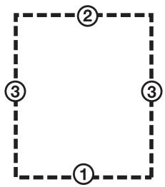
Cutting of blocks
First make the lower horizontal cut. Now make the upper horizontal cut. Finish with the two vertical cuts.
flowchart
graph TD
    A["①"] --> B["②"]
    B --> C["③"]
    C --> D["③"]
    D --> A
- If the upper horizontal cut is made before the lower horizontal cut, the work piece will fall on the blade and jam it.
- When making the last cut, the saw should be mounted on an adjacent fixed wall.
Track 400 series
- As the rail is symmetrical, the saw unit can be turned to make a new cut on the other side of the rail. In this way a cut piece is obtained that is in an easily handled size, making it easier to remove from the workplace.
- When the saw's is turned on the rail, the water jet will be positioned away from the blade and will spray in the opposite direction, possibly up towards the ceiling.
WS 460
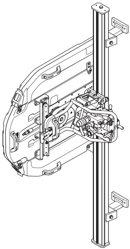
natural_image
Technical line drawing of a car suspension system with mechanical components and mounting brackets (no text or labels)It is our wish that you will be satisfied with your product and that it will be your companion for a long time. Think of this operator's manual as a valuable document. By following its content (using, service, maintenance etc) the life span and the second-hand value of the machine can be extended. If you will sell this machine, make sure that the buyer will get the operator's manual.
A purchase of one of our products gives you access to professional help with repairs and services whenever this may be necessary. If the retailer who sells your machine is not one of our authorised dealers, ask him for the address of your nearest service workshop.
Husqvarna Construction Products has a policy of continuous product development. Husqvarna reserves the right to modify the design and appearance of products without prior notice and without further obligation introduce design modifications.
General
- Hydraulic travel feed
• Adjustable control of travel feed
• Adjustable travel feed force - Separate saw carriage for faster setup.
- The saw unit is easily mounted on the carriage using a quick mounting bracket.
• The cutting arm can be rotated 360°. - The cutting arm allows blades up to 1 000 mm (40") to be used as the start blade.
- The saw unit has two slip clutches that prevent the saw from being damaged if it should jam.
Mount wall mountings and rail
WS 460 is supplied with two types of wall mounting and rail. The type of rail supplied depends on the market and the customer's requirements.
Track 360
1 Mark off the cutting line and mark off the expander bolts holes 165 mm (6,5") from the cutting line.
2 Drill 15 mm (5/8") holes for the M12 (1/2") expander bolts.
3 If the expander bolt pulls out when the mount is fixed or when mounting on brick, stone or hollow concrete walls, it may be necessary to "through-bolt" with a piece of thread bar and a large backing plate installed on the opposite side of the wall.
4 Hang the wall mountings loosely from the expander bolts, using M6S 12 x 70 (1/2"x2") or similar.
5 Level the brackets with the leveling screws so that the top of the brackets are parallel with the plane of the wall.
6 Secure the track to the brackets with T-washers and capscrews. The gear rack should be to the side of the track nearest the cut line.
7 Adjust the distance between the cutting line and the wall mounting. The distance between the edge and the inner face of the saw cut should be 95 mm (3,7"). Tighten the expander bolts.
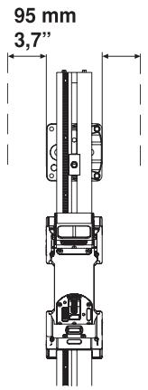
IMPORTANT! Make sure that the safety stops are fastened at each end of the track to prevent the saw from running off the track.
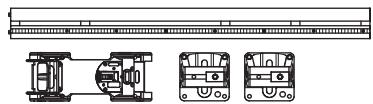
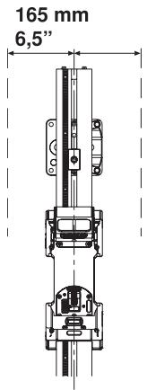
Track 400 series
natural_image
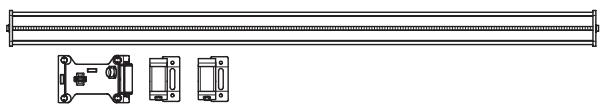
Technical line drawing of a mechanical component with two views and a horizontal bar (no text or symbols)1 Mark off the cutting line and mark off the expander bolts holes 165 mm (6.5") from the cutting line.
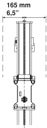
2 Drill 15 mm (5/8") holes for the M12 (1/2") expander bolts.
3 Hang the wall mountings loosely from the expander bolts, using M6S 12 x 70 (1/2"x2") or similar.
4 Level the brackets with the leveling screws so that the top of the brackets are parallel with the plane of the wall.
5 Place the rail in the wall mountings and tighten the compression washers.
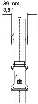
For vertical cuts, the rail must be mounted with the saw carriage lock handle upwards. This to facilitate fitting the saw unit.
6 Adjust the distance between the cutting line and the wall mounting. The distance between the edge and the inner face of the saw cut should be 89 mm (3.5"). Tighten the expander bolts.
IMPORTANT! Only use the connectors supplied when purchasing the saw as older connectors are not designed for the WS 400 series.
Mount the saw carriage and saw

Track 360
1 Push the retention rollers outward to the release position. This allows the saw carriage to be placed on the track with no interference.
natural_image
Technical line drawing of a mechanical device with multiple ports and mounting holes (no text or symbols)For vertical cuts, the rail must be mounted with the saw carriage lock handle upwards. This to facilitate fitting the saw unit.
2 Place the saw carriage on the track. Make sure that the pinion gear meshes properly with he track rack and that the saw is down firmly on the track. Push the retention rollers inward to the lock position.
3 Fit the saw body in the saw carriage by lifting the saw body into position. When the saw is lifted into position, the locking handle moves up into an intermediate position. In this position the saw remains in the saw carriage without it needing to be held. However, it is not sufficiently secured to begin cutting.
natural_image
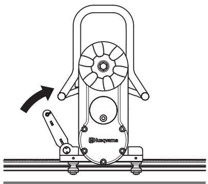
Technical line drawing of a mechanical device with fan and base components (no text or symbols)4 To secure the saw, lift the locking handle towards the saw until the handle locks.
natural_image
Technical line drawing of a mechanical device with fan and base components (no text or symbols)
WARNING! To cut without the saw securely assembled in the saw carriage and rail is associated with mortal danger.
Track 400 series
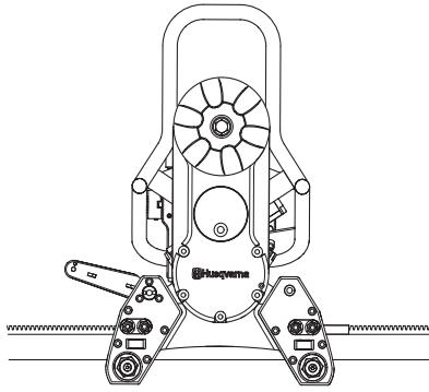
The saw carriage is mounted on the rail at delivery. The carriage can be dismounted from the rail by removing the end stop on the rail and pulling the carriage away.
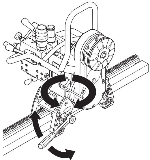
1 Fit the saw body in the saw carriage by lifting the saw body into position. When the saw is lifted into position, the locking handle moves up into an intermediate position. In this position the saw remains in the saw carriage without it needing to be held. However, it is not sufficiently secured to begin cutting.
natural_image
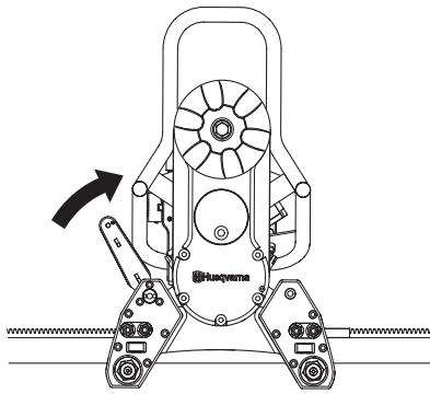
Technical line drawing of a mechanical device with no visible text or symbols2 To secure the saw, lift the locking handle towards the saw until the handle locks.
natural_image
Technical line drawing of a mechanical device with rotating fan and lever mechanism (no text or symbols)
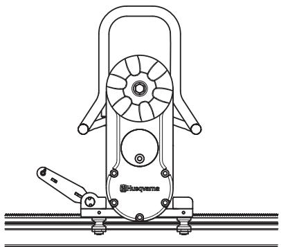
WARNING! To cut without the saw securely assembled in the saw carriage and rail is associated with mortal danger.
Fit the blade

WARNING! Never mount or dismount the blade or blade guard without first switching off the hydraulic unit and disconnecting the hydraulic hoses running to the saw unit. Carelessness can result in serious personal injury or even death.
1 Start by removing any dirt from the contact surfaces on the blade flange and blade.
2 Check the blade's direction of rotation. The blade shall rotate with the exposed part of the diamond in the rotational direction of the blade.
3 Screw together the outer blade flange, blade and blade flange hub (tightening torque 70-80 Nm).
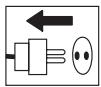
natural_image
Line drawing of a hand using a tool to lift a circular tire (no text or symbols)4 Hang the blade with the blade flange and blade flange hub fitted on the cutting arm (blade is not shown in the figure).
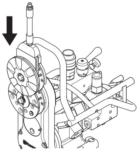
natural_image
Technical line drawing of an engine assembly with no visible text or symbols5 Turn the blade flange hub carefully so that it slides into one of the tracks in the pivot arm and lands in the correct position to be screwed fast.
6 Press in the blade spindle into the cutting arm at the same time as the blade is rotated carefully. When the blade spindle can no longer be pressed in by hand it should be tightened using the supplied 18-spanner until it is properly secured (tightening torque 70-80 Nm).
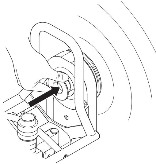
natural_image
Technical line drawing of a mechanical assembly with rotating components and motion arrows (no text or symbols)
WARNING! Exercise care when assembling the blade so that it does not risk becoming loose when cutting. Carelessness can result in serious personal injury or even death.
Flush cutting
When cutting flush, screw the blade directly onto the blade flange hub.
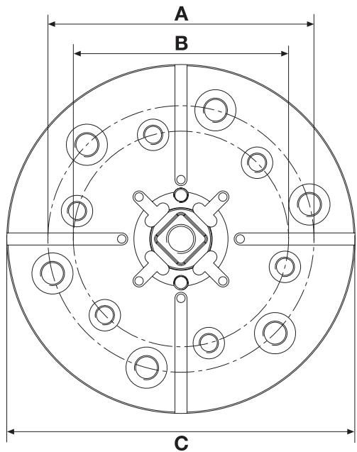
A=110 mm/4.33 inch, 6xM10
B=89 mm/3.5 inch, 6xM8
C=144 mm/5.7 inch
Fit the blade guard


WARNING! Never mount or dismount the blade or blade guard without first switching off the hydraulic unit and disconnecting the hydraulic hoses running to the saw unit. Carelessness can result in serious personal injury or even death.
1 Slip in the blade guard guide between the stays on the blade guard. Place the blade guard guide in the middle. Lock the plastic heel on the handle to the upper stay on the blade guard.
natural_image
Line drawing of a hand using a tool to adjust or install a mechanical component (no text or symbols present)2 Make sure that the pivot arm is positioned vertically. Lift the blade guard over the blade and hang the guard in the blade guard holder on the saw. Exercise care so that the runners on the blade guard are positioned in the slots on the water block.
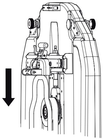
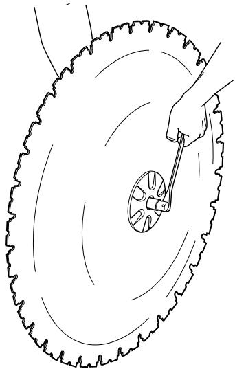
natural_image
Technical line drawing of a mechanical device with a downward arrow indicating motion or assembly (no text or symbols present)3 Lock the blade guard by pulling the handle out of the guard and then down towards the saw unit so that the latch locks the handle.
4 To remove the guard, release the latch and pull the handle upwards and inwards to the guard. Lock the plastic heel on the upper stay.
natural_image
Technical line drawing of a mechanical assembly with no visible text or symbolsConnect the hydraulic unit
Please read the operator's manual supplied with the hydraulic unit before using the machine.
When the saw unit, the blade and the blade guard are mounted, the hydraulic hoses and the water cooling should be connected.
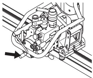
The pressure hose from the hydraulic unit shall be connected to the connector next to the start/stop switch for the blade rotation.
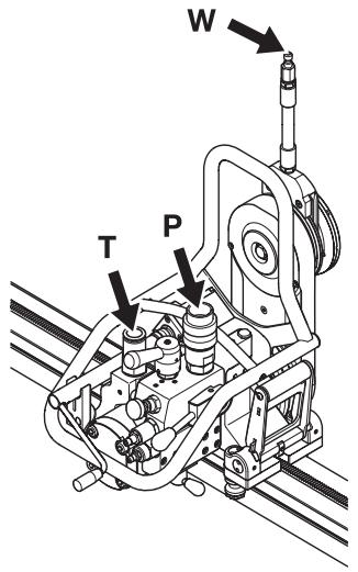
P=Pressure
T=Tank
W=Water
Adjust the flow to the saw unit for the desired speed of the blade. See the table in the chapter Technical data.
CAUTION! Max. flow to the saw unit is 27 GPM.
IMPORTANT! This machine is intended for use together with a Husqvarna PP 3300, Husqvarna PP 2525 and Husqvarna PP 2325. If the saw is used with another hydraulic unit, the unit must be compatible with the conditions required by the saw.
STARTING AND STOPPING
Before starting

- Enclose the area to be cut so that unauthorised persons can not be injured or disturb the operator.
- Check that the blade and th blade guard is not damaged or cracked. Replace the blade or the blade guard if it is exposed to impact or is cracked.
- Make sure that all hydraulic hoses and connections are intact and correctly connected, and that the water cooling is correctly connected and switched on.
- Check the oil level in the cutting unit. Adjust the speed valve on the saw motor to the correct position, depending on the blade diameter. (See the Cutting capacity table).
natural_image
Technical line drawing of a mechanical assembly with pipes and gears (no text or symbols)- If cutting is to begin in another position than where the saw unit is located, run the saw unit to the start position.
Starting

1 Turn on the hydraulic unit.
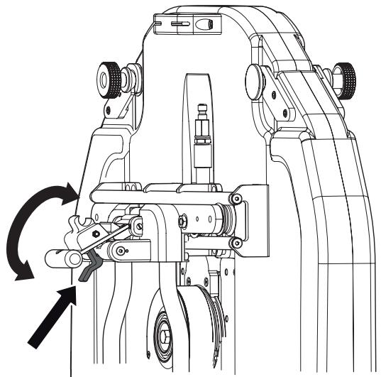
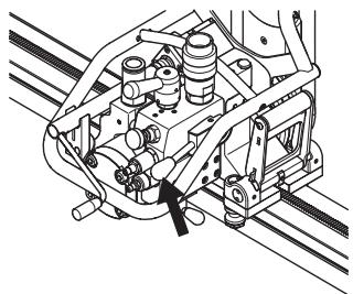
2 Start the blade rotation by pushing the lever for starting/ stopping the blade rotation in towards the block and then carefully pull the lever up towards the hose connector.
natural_image
Technical line drawing of a mechanical assembly with hoses and components (no text or symbols)3 The blade is manually moved to the required depth.
natural_image
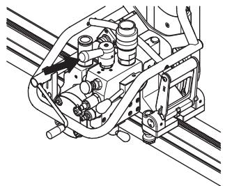
Technical line drawing of a mechanical assembly with no visible text or symbols4 Start the travel feed. Turn the handle on the directional control valve for travel feed, so that the saw moves in the required direction.
natural_image
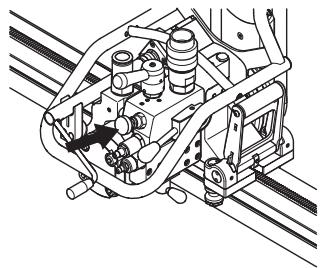
Technical line drawing of a mechanical assembly with springs and bolts (no text or symbols)If the blade meets resistance during the cutting, a valve stops the travel feed automatically. The travel feed starts automatically again when the resistance decreases and the pressure returns to the normal.
5 The speed of the travel feed is controlled with the valve for adjustment of travel feed force. Adjust the valve to the desired position.
If the travel feed "jerks", the cause may be too high feed, which releases the valve for travel feed control and the travel feed stops. Lower the travel feed force until the feed is even.
natural_image
Technical line drawing of a mechanical assembly with pipes and gears (no text or symbols)Stopping
1 Once cutting is completed, remove the blade from the wall and shut down the blade rotation and the water flow.
2 Shut down the hydraulic unit.
Dismantling the saw
1 Allow the motor to stop completely.
2 Switch off the power to the hydraulic unit.
3 Disconnect the hydraulic hoses and the water hose from the saw unit.
The other steps are done in the reverse order to assembling.
Cleaning
The saw should be cleaned once cutting is finished. It is important to clean all the saw equipment. The saw is best cleaned with the supplied cleaning brush by connecting it to the water hose.
IMPORTANT! Do not use a high pressure washer to clean the saw.
Track 360
Adjusting the rollers
In order for the saw to run stable and cut a straight line, the rollers must be in contact with the track and not have too much play. When there is too much play between the saw carriage and track the rollers must be adjusted.
Adjusting the lower rollers
The lower rollers should be adjusted if vertical play is observed between the saw carriage and the track.
To adjust, loosen the four 6 mm socket head setscrews located at the bottom of the saw carriage. Loosening the setscrews will allow you to turn the lower eccentric bushing.
Place a 0.05-0.08 mm (0,002"-0,003") shim between the roller you are adjusting and the track. Rotate the eccentric bushing using a 27 mm (1-1/6") socket until the shim is held firmly between the roller and the track but you can still pull it out. Once this is achieved re-tigten the 6 mm socket head setscrews.
natural_image
Technical line drawing of a mechanical assembly with a wrench and rotating mechanism (no text or symbols)NOTE!
Do not over tighthen the 6 mm socket head setscrews. This could cause a slight deformity in the eccentric brushing which could cause the plunge portion of the roller to stick.
NOTE!
The upper rollers located directly underneath the saw carriage are fixed and cannot be adjusted.
Adjusting the side rollers
The side rollers should be adjusted if side play is observed between the saw carriage and the track.
To adjust, loosen the 4 mm socket head setscrew located on the side of two of the saw carriage legs. Place a 0.05-0.08 mm (0,002"-0,003") shim between the roller you are adjusting and the track. To adjust, loosen the 4 mm socket head setscrew located on the side of two of the saw carriage legs. Re-tighten the 4 mm socket head setscrew. Repeat on the other adjustable side roller.
natural_image
Technical line drawing of a mechanical device with rotating components and a handle (no text or symbols)NOTE!
Make sure that the carriage can be removed and re-installed on the track. If it is difficult to re-assemble on the track, it is being held-up by the side roller and needs to be re-adjusted for more clearance.
Adjusting the locking handle
As the saw wears, the locking handle may need to be adjusted if play is noticed between the saw head and the saw carriage.
To adjust the locking handle, loosen the two top 6 mm socket head setscrews (one on each side of the handle mount). Turn the eccentric bushing with the supplied adjustment tool until the cam lies tight against the saw head. Tighten the top 6 mm socket head setscrew. Adjust the other side. Remove saw head and tighten the lower 6 mm socket head setscrew on both sides.
natural_image
Technical line drawing of a mechanical assembly with rotating components and motion arrows (no text or symbols)Adjusting the friction stop
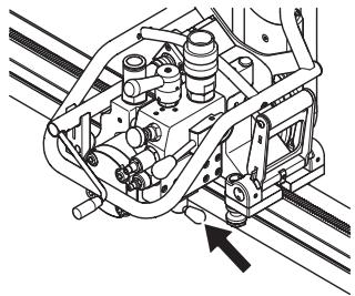
The friction stop must momentarily support the combined weight of the saw carriage and saw head when mounted on the track with the track mounted vertically to the wall.
To adjust the friction stop, remove the saw head from the carriage. Mount the carriage on the track and turn the friction stop setscrew clockwise to apply additional force of friction. The friction stop only needs to support the carriage and saw head until the mating gears engage.
natural_image
Technical line drawing of a mechanical assembly with a black arrow pointing to a component (no text or symbols present)Track 400 series
Adjusting the guide wheels
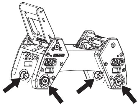
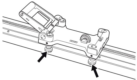
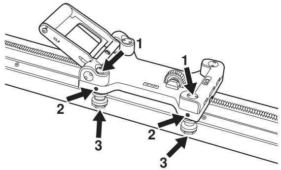
In order for the saw to run stably and saw a straight cut, the four guide wheels must rest against the rail and not have too much play. When there is too much play between the saw carriage and rail the guide wheels must be adjusted:
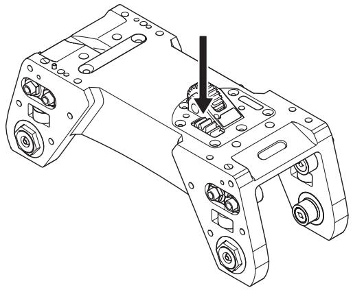
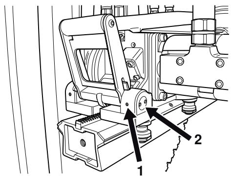
The two marked guide wheels have eccentric axles and by turning these the carriage is tightened onto the rail.
natural_image
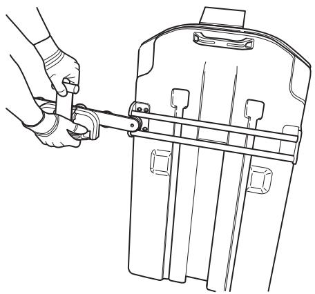
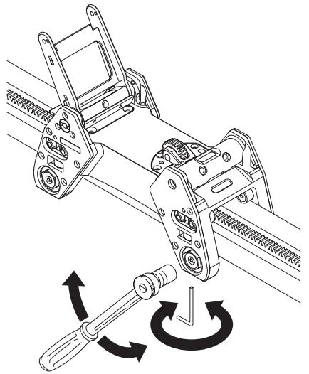
Technical line drawing of a mechanical assembly with two mounting holes and rail tracks (no text or symbols)Start by loosening the marked nuts (1) with the supplied special tool. Now loosen the two stop screws (2). When these are loose, adjust the guide wheels (3) against the rail by turning them towards the rail so the play is taken up. Hold the guide wheels and screw in the stop screw. Now screw on the nuts to secure the guide wheels in the new position.
Adjust the saw carriage
As the saw wears, after a number of hours working, it can be a good idea to ensure that the saw sits firmly in the saw carriage and rail. If not, the handle probably needs adjusting:
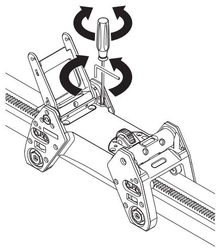
Loosen the marked (1) socket headed screw (one on each side of the handle). Now turn the eccentric axles (2) with the help of the supplied special tool until the axle lies tight against the saw. Now tighten the socket headed screw.
Maintenance

IMPORTANT! Inspection and/or maintenance should be carried out with the motor switched off and the plug disconnected.
In addition to the daily maintenance such as cleaning and lubrication, the machine must be serviced. After 50 hours of cutting, the machine should be serviced at an accredited Husqvarna workshop. The saw should then be serviced after every 100 hours of operation. The service is important so that as the user you have a machine that works as effectively as possible for a long time.
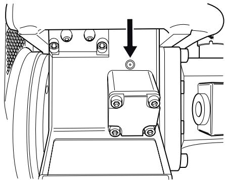
Oil change cutting arm
There is an oil plug for draining the oil located on the cutting arm. This plug should be cleaned when changing the oil. The new oil is filled through the hole where the oil plug sits.
natural_image
Technical line drawing of a mechanical assembly with no visible text or symbolsThe cutting arm contains 1 dl of Husqvarna Oil 150, a transmission oil of the type EP 150. The oil should be replaced for the first time in connection with the first service. A 1 dl bottle of oil is supplied when the machine is new.
IMPORTANT! Used engine oil and transmission oil is hazardous to health and must not be disposed of in the ground or out of doors.
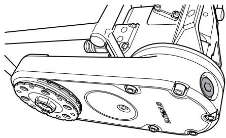
Lubricating the gears
There are two grease nipples on every saw unit. Through these the gears for the feeding engines can be lubricated.
natural_image
Technical line drawing of a vehicle interior showing a vehicle chassis with a load valve and mounting bracket (no text or symbols)Lubricate daily or at least every 30 hours of operation. Use VEIDEC POWER LUBE or corresponding grease.
Grease the blade spindle
In order for the blade spindle to be fitted as easily as possible, it may be necessary to grease the hexagonal blade spindle. At the same time check that the hexagon is not damaged.
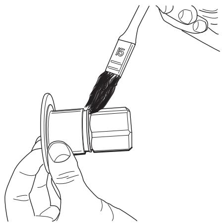
natural_image
Line drawing of a hand holding a small mechanical component with a brush applying material (no text or symbols)IMPORTANT! All types of repairs may only be carried out by authorised repairmen. This is so that the operators are not exposed to great risks.
Repairs
IMPORTANT! All types of repairs may only be carried out by authorised repairmen. This is so that the operators are not exposed to great risks.
Daily maintenance
1 Ensure the blades are not cracked or damaged in any other way.
2 Check that the blade guard is not damaged or cracked. Replace the blade guard if it is exposed to impact or is cracked.
3 Clean the outside of the machine.
Do not use a high pressure washer to clean the saw.
4 Check that all couplings, connections and hydraulic hoses are in full working order.
TECHNICAL DATA
WS 460
Weight, kg/lbs
| Saw unit | 28/62 |
| Blade flange hub | 3,8/8,3 |
| Blade guards | 15/33 |
| Track 400 series 1.2m/47” | 12,2/26,9 |
| Track 400 series 2m/80” | 17,2/37,9 |
| Track 400 series 2.2m/90” | 16,6/36,5 |
| Track 360 1m/40” | |
| Track 360 1.3m/51” | |
| Track 360 3m/120” | 17,2/37,9 |
| Saw carriage 400 series | 3,7/8,2 |
| Saw carriage 360 | 6,6/14,3 |
| Hydraulic fluid flow, max, l/m / gpm | 102/27 |
| Pressure max, bar/psi | 206/3000 |
| Travel feed | Hydraulic |
| Depth feed | Manual |
| Sound power level, measured, EN 61029 (2007), dB(A) | 117,8 |
| Noise pressure level at the operators ear, measured according to EN 61029 (2007), dB(A) | 100,3 |
Saw depth, inch
| Blade diameter, inches | Saw depth - max, inch |
| 24 | 9 |
| 30 | 12 |
| 36 | 15 |
| 42 | 18 |
| 48 | 21 |
Saw depth, mm
| Blade diameter, mm | Saw depth - max, mm |
| 600 | 230 |
| 800 | 330 |
| 1000 | 430 |
| 1200 | 530 |
Blade speeds and flow requirements
| Blade diameter, mm | Spindle speed, rpm | Max. peripheral speed, m/s | Flow to the saw unit, l/min | Gear in the saw unit |
| 600 | 1300-1500 | 40-47 | 90-100 | 2 |
| 800 | 1100-1300 | 46-54 | 80-90 | 2 |
| 1000 | 900-1000 | 47-52 | 95-100 | 1 |
| 1200 | 800-900 | 50-56 | 85-95 | 1 |
| Blade diameter, inches | Spindle speed, rpm | Max. peripheral speed, ft/min | Flow to the saw unit, gpmGear in the saw unit | |
| 24 | 1300-1500 | 8164-9420 | 24-27 | 2 |
| 30 | 1300-1500 | 10205-11775 | 24-27 | 2 |
| 36 | 1100-1300 | 10362-12246 | 21-24 | 2 |
| 42 | 900-1000 | 9891-10990 | 26-27 | 1 |
| 48 | 800-900 | 10048-11304 | 23-26 | 1 |
Spindle speed at various flows
| 18 gpm | 20 gpm | 25 gpm | 27 gpm | |
| Gear 1 | 600 | 700 | 850 | 950 |
| Gear 2 | 1000 | 1100 | 1400 | 1500 |
Never use blades other than original blades designed for the machine.
EC-declaration of conformity
Husqvarna Construction Products, SE-433 81 Göteborg, Sweden, tel: +46-31-949000, declares under sole responsibility that the wall saw Husqvarna WS 460, from 2008's serial numbers and onwards (the year is clearly stated in plain text on the rating plate with subsequent serial number), conforms with the requirements of the COUNCIL'S DIRECTIVE:
• of June 22, 1998 "relating to machinery" 98/37/EC, annex IIA.
The following standards have been applied:
The supplied wall saw conforms to the example that underwent EC type examination.
Göteborg January 5, 2008
$$ \mathrm {C l i n c o l l i n g} $$
Christer Carlberg
Managing Director
natural_image
Line drawing of a mechanical component with no visible text or symbolsnatural_image
Line drawing of a pair of trousers with a belt buckle (no text or symbols)natural_image
Technical line drawing of a mechanical assembly with no visible text or symbolsnatural_image
Technical line drawing of a mechanical component with two views: top shows horizontal bar, bottom shows front view with mounting bracket (no text or symbols)natural_image
Technical line drawing of a mechanical device with multiple ports and mounting holes (no text or symbols)natural_image
Technical line drawing of a mechanical device with no visible text or symbolsnatural_image
Technical line drawing of a mechanical device with no visible text or symbols
natural_image
Technical line drawing of a mechanical device with no visible text or symbolsnatural_image
Mechanical diagram of a mechanical device with rotating components and a directional arrow (no text or symbols)
natural_image
Line drawing of a hand using a tool to lift a tire, no text or symbols presentnatural_image
Technical line drawing of an engine assembly with no visible text or symbolsnatural_image
Technical line drawing of a mechanical assembly with motion arrows indicating motion (no text or symbols)
natural_image
Line drawing of a hand using a tool to lift a rectangular device (no text or symbols)natural_image
Technical line drawing of a mechanical device with no visible text or symbolsnatural_image
Technical line drawing of a mechanical device with rotational arrows indicating motion (no text or symbols)natural_image
Technical line drawing of a mechanical assembly with pipes and gears (no text or symbols)natural_image
Technical line drawing of a mechanical assembly with springs and tubing (no text or symbols)natural_image
Technical line drawing of a mechanical assembly with pipes and gears (no text or symbols)natural_image
Technical line drawing of a mechanical assembly with no visible text or symbolsnatural_image
Technical line drawing of a mechanical assembly with springs and gears (no text or symbols)Parada
natural_image
Technical line drawing of a mechanical assembly with a wrench and circular motion arrows (no text or symbols)NOTE!
natural_image
Technical line drawing of a mechanical device with rotating components and directional arrows (no text or symbols)NOTE!
natural_image
Technical line drawing of a mechanical assembly with rotating components and motion arrows (no text or symbols)natural_image
Technical line drawing of a mechanical assembly with a highlighted component (no text or symbols)Riel, serie 400
natural_image
Technical line drawing of a mechanical assembly with springs and levers (no text or symbols)Mantenimiento

natural_image
Technical line drawing of a mechanical assembly with no visible text or symbolsnatural_image
Technical line drawing of a vehicle chassis with a car body and directional arrow indicating motion (no text or symbols)natural_image
Line drawing of a hand holding a small mechanical component with a brush applying material (no text or symbols)natural_image
Line drawing of a mechanical component with a flanged handle and circular end (no text or symbols)natural_image
Line drawing of a pair of trousers with a belt buckle (no text or symbols)natural_image
Technical line drawing of a car suspension system with mechanical components and mounting brackets (no text or labels)natural_image
Technical line drawing of a mechanical component with three views: top view, front view, and side view (no text or symbols)natural_image
Technical line drawing of a mechanical device with two ports and directional arrows indicating assembly or movement (no text or symbols present)natural_image
Technical line drawing of a mechanical device with no visible text or symbolsnatural_image
Technical line drawing of a mechanical device with no visible text or symbols
natural_image
Technical line drawing of a mechanical device with rotating components and mounting base (no text or symbols)natural_image
Technical line drawing of a mechanical device with a rotating wheel and lever mechanism (no text or symbols)
natural_image
Line drawing of a hand using a tool to lift a circular tire (no text or symbols)natural_image
Technical line drawing of a mechanical assembly with no visible text or symbolsnatural_image
Mechanical assembly diagram showing a hand operating a wheel with rotating wheels (no text or symbols)
natural_image
Line drawing of a hand using a tool to adjust or install a mechanical component (no text or symbols present)natural_image
Technical line drawing of a mechanical device with no visible text or symbolsnatural_image
Technical line drawing of a mechanical device with rotational arrows indicating motion (no text or symbols)natural_image
Technical line drawing of a mechanical assembly with pipes and gears (no text or labels)natural_image
Technical line drawing of a mechanical assembly with hoses and components (no text or symbols)natural_image
Technical line drawing of a mechanical assembly with pipes and housing (no text or symbols)natural_image
Technical line drawing of a mechanical assembly with no visible text or symbolsnatural_image
Technical line drawing of a mechanical assembly with no visible text or symbolsStoppen
natural_image
Technical line drawing of a mechanical assembly with a wrench and circular motion arrows (no text or symbols)NOTE!
natural_image
Technical line drawing of a mechanical device with rotating arrows indicating motion (no text or symbols)NOTE!
natural_image
Technical line drawing of a mechanical assembly with rotating components and motion arrows (no text or symbols)natural_image
Technical line drawing of a mechanical assembly with no visible text or symbolsnatural_image
Technical line drawing of a mechanical assembly with springs and railings (no text or symbols)Wartung

natural_image
Technical line drawing of a mechanical assembly with no visible text or symbolsnatural_image
Technical line drawing of a vehicle interior showing a vehicle chassis with wheels and a directional arrow indicating motion (no text or symbols)natural_image
Line drawing of a hand holding a tool near a ring, with no visible text or symbolsnatural_image
Line drawing of a mechanical component with a flanged handle and circular base (no text or symbols)natural_image
Line drawing of a pair of trousers with a belt buckle (no text or symbols)natural_image
Technical line drawing of a car suspension system with mechanical components and mounting brackets (no text or labels)natural_image
Technical line drawing of a mechanical assembly with three views (top, front, side) showing internal components and alignment lines (no text or symbols)natural_image
Technical line drawing of a mechanical component with two views and a horizontal bar (no text or symbols)natural_image
Technical line drawing of a mechanical device with multiple ports and directional arrows indicating assembly or movement (no text or symbols present)natural_image
Technical line drawing of a mechanical device with no visible text or symbolsnatural_image
Technical line drawing of a mechanical device with no visible text or symbols
natural_image
Technical line drawing of a mechanical device with no visible text or symbolsnatural_image
Mechanical diagram of a mechanical device with rotating components and a directional arrow (no text or symbols)
natural_image
Line drawing of a hand using a tool to lift a tire, no text or symbols presentnatural_image
Technical line drawing of a mechanical assembly with no visible text or symbolsnatural_image
Technical line drawing of a mechanical assembly with motion arrows indicating motion (no text or symbols)
natural_image
Line drawing of a hand using a tool to lift a rectangular device (no text or symbols)natural_image
Technical line drawing of a mechanical device with no visible text or symbolsnatural_image
Technical line drawing of a mechanical device with no visible text or symbolsnatural_image
Technical line drawing of a mechanical assembly with pipes and gears (no text or symbols)natural_image
Technical line drawing of a mechanical assembly with springs and tubing (no text or symbols)natural_image
Technical line drawing of a mechanical assembly with no visible text or symbolsnatural_image
Technical line drawing of a mechanical assembly with pipes and gears (no text or symbols)natural_image
Technical line drawing of a mechanical assembly with no visible text or symbolsArrêt
natural_image
Technical line drawing of a mechanical assembly with a wrench and circular motion arrows (no text or symbols)NOTE!
natural_image
Technical line drawing of a mechanical device with rotating components and a handle (no text or symbols)NOTE!
natural_image
Mechanical assembly diagram showing a rotating mechanism with pulleys and gears (no text or labels)natural_image
Technical line drawing of a mechanical assembly with a black arrow pointing to a component (no text or symbols present)Rail - Série 400
natural_image
Technical line drawing of a mechanical assembly with springs and railings (no text or symbols)Entretien

natural_image
Technical line drawing of a mechanical component with no visible text or symbolsnatural_image
Technical line drawing of a vehicle interior showing a vehicle chassis with a load valve and mounting bracket (no text or symbols)natural_image
Line drawing of a hand holding a small mechanical component with a brush applying material (no text or symbols)- Operator's manual
- Symbols on the machine:
- Always wear:
- Symbols in the operator's manual:
- Contents
- KEY TO SYMBOLS
- WHAT IS WHAT?
- SAFETY INSTRUCTIONS
- PRESENTATION
- ASSEMBLY
- STARTING AND STOPPING
- SETTINGS AND ADJUSTMENTS
- MAINTENANCE
- TECHNICAL DATA
- What is what on the wall saw?
- Steps before using a new wall saw
- Always use common sense
- Personal protective equipment
- General safety precautions
- Transport and storage
- General working instructions
- Basic working techniques
- Cutting of blocks
- Track 400 series
- General
- Mount wall mountings and rail
- Mount the saw carriage and saw
- Track 360
- Fit the blade
- Flush cutting
- Fit the blade guard
- Connect the hydraulic unit
- Before starting
- Starting
- Stopping
- Dismantling the saw
- Cleaning
- Adjusting the rollers
- Adjusting the lower rollers
- NOTE!
- Adjusting the side rollers
- Adjusting the locking handle
- Adjusting the friction stop
- Adjusting the guide wheels
- Adjust the saw carriage
- Oil change cutting arm
- Lubricating the gears
- Grease the blade spindle
- Repairs
- Daily maintenance
- WS 460
- Saw depth, inch
- Saw depth, mm
- Blade speeds and flow requirements
- Spindle speed at various flows
- EC-declaration of conformity
- Parada
- Riel, serie 400
- Mantenimiento
- Stoppen
- Wartung
- Arrêt
- Rail - Série 400
- Entretien
Brand : HUSQVARNA
Model : WS 460
Category : Concrete saw