TC 250 - Motorcycle HUSQVARNA - Free user manual and instructions
Find the device manual for free TC 250 HUSQVARNA in PDF.


| Product Type | Off-road competition motorcycle |
| Brand | HUSQVARNA |
| Model | TC 250 |
| Engine | Single-cylinder 4-stroke, liquid cooling, 249.5 cm³, bore 76 mm, stroke 55 mm, compression ratio 12.9:1 |
| Fuel System | Unleaded gasoline 98 octane, tank 9.2 L (reserve 1.8 L), carburetor Keihin FCR-MX 37 mm |
| Ignition | Capacitive discharge electronic, digital variable advance, spark plug NGK CR8EB (gap 0.7 mm) |
| Primary Drive | Pinion 20 teeth, crown 67 teeth, ratio 3.350 |
| Transmission | 6-speed constant mesh, ratios: 1st 1.866, 2nd 1.529, 3rd 1.263, 4th 1.086, 5th 0.954 |
| Clutch | Multi-disc oil bath, hydraulic actuation |
| Secondary Drive | Chain, pinion 12 teeth, crown 50 teeth, ratio 4.166 |
| Front Suspension | Inverted telescopic hydraulic fork, stem Ø 45 mm, travel 300 mm, adjustable compression and rebound |
| Rear Suspension | Progressive with hydraulic mono-shock, travel 325 mm, adjustable preload, compression and rebound |
| Brakes | Front: fixed disc Ø 260 mm, hydraulic floating caliper; Rear: floating disc Ø 240 mm, hydraulic floating caliper |
| Tires | Front: 80/100 x21" Pirelli MT 32; Rear: 100/90 x19" Pirelli MT 32; cold pressure front 0.9-1.0 kg/cm², rear 0.8-0.9 kg/cm² |
| Dimensions (L x W x H) | 2200 mm x 820 mm x 1270 mm |
| Seat Height | 970 mm |
| Instrumentation | Digital display with speed, odometer, trips, clock, RPM, max speed, average speed, ride time |
| Starting | Kick-start with automatic and manual decompressor |
| Coolant | Capacity 1.1-1.3 L |
| Engine/Transmission Oil | Oil change with filter: 1.7 L; simple drain: 1.5 L. See lubrication table page 44 |
| Safety | Hydraulic brakes, steering lock, emergency engine stop, manual decompressor |
| Periodic Maintenance | Oil change, level checks, air filter cleaning, chain adjustment, general lubrication, brake and suspension inspection |
Frequently Asked Questions - TC 250 HUSQVARNA
User questions about TC 250 HUSQVARNA
0 question about this device. Answer the ones you know or ask your own.
Ask a new question about this device
Download the instructions for your Motorcycle in PDF format for free! Find your manual TC 250 - HUSQVARNA and take your electronic device back in hand. On this page are published all the documents necessary for the use of your device. TC 250 by HUSQVARNA.
USER MANUAL TC 250 HUSQVARNA
natural_image
Side view of a white and black Husqvarna TE250 motorcycle with visible tracks and wheels (no text or symbols on the bike body)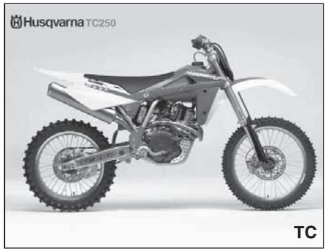
natural_image
Side view of a Mascat 250 motorcycle with visible tracks and wheels (no text or symbols on the vehicle itself)R: A RICHIESTA (VEDERE PAGINE 262 e 266)
R: UPON REQUEST (SEE PAGES 262 and 266)
R: SUR DEMANDE (VOIR PAGES 262 et 266)
R: AUF ANFRAGE (SEHEN SEITEN 262 und 266)
R: BAJO PEDIDO (VER PÁGINAS 263 y 267)
natural_image
Side view of a white and gray semi-motor motorcycle with visible engine and wheels (no text or symbols on the bike body)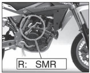
text_image
R: SMR
natural_image
Stylized black-and-white graphic of a stylized character resembling a bell or hat with a crown-like shape (no text or symbols)TE 250-450-510, TC 250-450-510, SMR 400-450-510/2006
CARATTERISTICHE - USO - MANUTENZIONE SPECIFICATIONS - OPERATION - MAINTENANCE CARACTERISTIQUES - UTILISATION - ENTRETIEN MERKMALE - GEBRAUCH - WARTUNG CARACTERISTICAS - USO - MANTENIMIENTO
Unless specified, data and prescription are referred to all t he models.
Welcome to the Husqvarna motorcycling Family!
Your new Husqvarna motorcycle is designed and manufactured to be the finest in its field. The instructions in this book have been prepared to provide a simple and understandable guide for your motorcycle's operation and care.
Follow the instructions carefully to obtain maximum performance and your personal motorcycling pleasure. Your owner's manual contains instructions for owner care and maintenance. Information covering repair of major units such as engine, transmission, etc. is provided in the Husqvarna Service Manual. The information concerning details or main work of repair or maintenance are described in the Husqvarna Service Manual. This manual is available upon request by stating the code number set on pages 262, 264, 266. Work of this kind requires the attention of a skilled mechanic and the use of special tools and equipment.
Your Husqvarna dealer has the facilities, experience and original parts necessary to properly render this valuable service.
This “Owner’s Manual” and the “Purchase Registration Booklet” are parts and parcels of the motorcycle, hence, they have to remain with the motorcycle even when sold to another user. This motorcycle uses components designed thanks to systems and state of the art technologies which are thereafter tested in competition.
In competition motorcycles, every detail is verified after each race in order to always guarantee better performance. For correct functioning of the vehicle, it is necessary to follow the maintenance and control table found on page 282-288.
PRESENTATION
natural_image
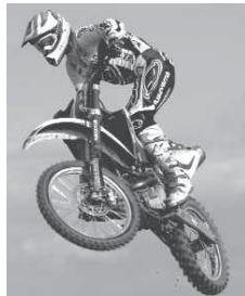
Side view of a Mascat 250 motorcycle with visible tracks and wheels (no text or symbols on the bike body)MOTOCROSS
natural_image
Black-and-white photo of a motorcyclist mid-jump, wearing gear and helmet (no visible text or symbols)AVIS IMPORTANT
1) The TC models are guaranteed COMPETITION motorcycles exempt from functional defects, the suggested maintenance table for competition use is shown on page 282.
natural_image
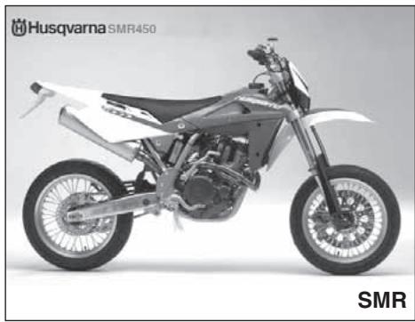
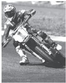
Side view of a white and gray semi-traw bike with visible dynamics and wheels (no text or symbols on the bike body)SUPERMOTARD
natural_image
Black-and-white photo of a motorcyclist in action on a paved field (no visible text or symbols)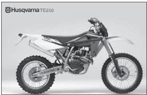
natural_image
Side profile of a white and black Mascat with visible wheels and engine components (no text or symbols on the bike body)ENDURO
natural_image
Person riding a dirt bike outdoors with mountainous background (no visible text or symbols)2) TE and SMR are STREET LEGAL motorcycles (with LIMITED POWER ENGINE); they are guaranteed exempt from functional defects and covered with legal guarantee, if the STANDARD CONFIGURATION is maintained and the suggested maintenance table, shown on page 288, is observed
natural_image
Side view of a Mascat 250 motorcycle with visible tracks and wheels (no text or symbols on the bike body)natural_image
Black-and-white photo of a motorcyclist mid-air during a jump, wearing gear and racing suit (no visible text or symbols)natural_image
Side profile of a white and gray semi-traw bike with visible dynamics and wheels (no text or symbols on the bike body)SUPERMOTARD
natural_image
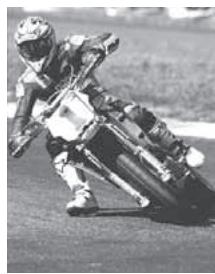
Motorcyclist in action on a paved field, wearing helmet and racing gear (no visible text or symbols)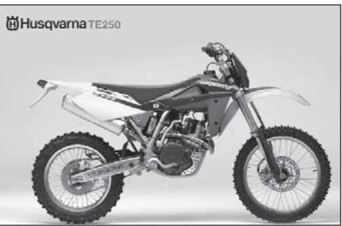
natural_image
Side view of a Husqvarna TE250 motorcycle with visible tracks and wheels (no text or symbols on the bike body)ENDURO
natural_image
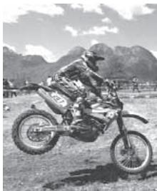
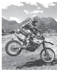
Black-and-white photo of a rider on a dirt bike in a grassy outdoor field with mountains in the background (no visible text or symbols)If TE and SMR are transformed in COMPETITION MOTORCYCLES (with FULL POWER ENGINE), the suggested maintenance table for competition use is shown on pages 282 and 288.
IMPORTANT
The reference for recognition of the guarantee will be the MOTORCYCLE CONFIGURATION, as shown below:
A) - STANDARD MOTORCYCLE, STREET LEGAL: with LIMITED POWER ENGINE B) - COMPETITION MOTORCYCLE, RACING USE: with FULL POWER ENGINE
This motorcycles was not designed for long trips with the engine always at maximum rpm as can occur whilst travelling on roads or highways. Long trips at full throttle can cause severe damage to the engine.
This motorcycles was not designed for urban use and is not equipped with a cooling fan and thermostat. Long stops at the traffic lights can cause overheating and the boiling of radiator water.
This motorcycles is setup for competition use and therefore guarantees maximum performance with the rider alone. It is thereby not recommended to use the vehicle on circuits or off-road with a passenger.
ALWAYS keep in mind that these motorcycles have been designed strictly for competition use, that is, for conditions of usage very different from those presented on the road.
In order to maintain the vehicle's “Guarantee of Functionality”, the client must follow the maintenance program indicated in the user's manual by carrying out maintenance checks at authorized HUSQVARNA dealers. The cost for substituting parts and for the labour necessary in order to respect the maintenance plan, is charged to the client. NOTE: the guarantee is EXTINGUISHED in the case where the motorcycle is rented.
Note
- References to the “left” or “right” of the motorcycle are in the sense of a person facing forwards.
● Z: number of teeth
● A: Austria
AUS: Australia
B: Belgium
BR: Brazil
CDN: Canada
CH: Switzerland
D: Germany
E: Spain
F: France
FIN: Finland
GB: Great Britain
I: Italy
J: Japan
USA: United States of America
- Where not specified, all the data and the instructions are referred to any and all Countries.
Read this manual carefully and pay special attention to statements preceded by the following words:
WARNING*: Indicates a possibility of severe personal injury or loss of life if instructions are not followed.
CAUTION*: Indicates a possibility of personal injury or equipment damage if instructions are not followed.
Note*: Gives helpful information.
Parts Replacement
When parts replacement is required, use only Husqvarna ORIGINAL parts.
Préliminaires
WARNING*: After an upset, inspect the motorcycle carefully. Make sure that the throttle, brake, clutch and all other systems are undamaged. Riding with a damaged motorcycle can lead to a serious crash.
WARNING*: Never attempt to start or operate your motorcycle unless you are wearing appropriate protective clothing. Always wear a motorcycle helmet, motorcycle boots, gloves, goggles and other appropriate protective clothing.
WARNING*: This motorcycle is a state of the art competition bike. Do not attempt to start or ride this motorcycle until you have received expert instruction and are in excellent physical condition.
PRECAUTIONS FOR CHILDREN WARNING
● Park the vehicle where it is unlikely to be bumped into or damaged. Even slight or involuntary bumps can cause the vehicle to topple over, with subsequent risk of serious harm to people or children.
● To prevent the vehicle from tipping over, never park it on soft or uneven ground, nor on asphalt strongly heated by the sun.
● Engine and exhaust pipes become very hot during riding. Always park your motorcycle where people or children can not easily reach these parts, in order to avoid serious burns.
LUBRICATION TABLE, SUPPLIES......44
CONTROLS 46
RIDING....80
SERVICE LIMITS....198
OPTIONAL PARTS LIST......262,264,266
APPENDIX 268
NOTE FOR USA/CDN- AUS MODELS .. 275-278
PRE-DELIVERY INSPECTION 279
PERIODIC MAINTENANCE - ADJUSTMENT....282-288
ALPHABETICAL INDEX 298
IDENTIFICATION DATA
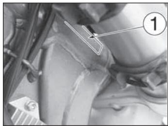
The engine number is printed on the upper side of the engine case, whereas the frame number is printed on the steering tube (see on page 20).
Always state the number stamped on the frame (and write it on this booklet), when placing orders for spare parts, or when asking for information on your motorcycle.
FRAME NUMBER
RESUME Page
PRESENTATION......4
AVIS IMPORTANT 6
ELEMENTS D'IDENTIFICATION......18
DONNEES TECHNIQUES ......26
TABLEAU DE GRAISSAGE, RAVITAILLEMENTS ....44
COMMANDES....46
MODE D'EMPLOI DE LA MOTO....80
LIMITE D'USURE ....198
SYSTEME D'ALLUMAGE/SYSTEME ELECTRIQUE....226-232
OUTILS SPECIAUX....250
COUPLES DE SERRAGE....252 KIT....260
ELEMENTS EN OPTION ......262,264,266
APPENDICE....268
NOTE POUR LES MODELES USA/CDN- AUS ....275-278
OPERATIONS DE PRÉ LIVRAISON .....280 ENTRETIEN PERIODIQUE -
REGLAGES....282-288
INDEX ALPHABETIQUE ....298
ELEMENTS D'IDENTIFICATION
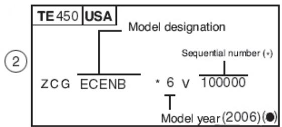
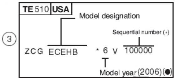
The full 17 digit serial, or Vehicle Identification Number, is stamped on the steering head tube (R.H. side).
NUMERO D'IDENTIFICATION DU MOTOCYCLE (V.I.N.)
(●): Year of the model
(●): An du modèle
natural_image
Close-up of mechanical components with a numbered label (1) pointing to a specific part, no readable text or symbols present.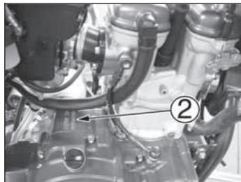
natural_image
Close-up of an internal mechanical assembly with hoses and components (no visible text or symbols)- Matricola telaio
- Matricola motore
- Matricule cadre
- Matricule moteur
- Frame serial number
- Engine serial number
- Rahmen Nr.
- Motor Nr.
- Matrícula bastidor
- Matrícula motor
NUMERO DI IDENTIFICAZIONE DEL MOTOCICLO (V.I.N.)
The full 17 digit serial, or Vehicle Identification Number, is stamped on the steering head tube (R.H. side).
NUMERO D'IDENTIFICATION DU MOTOCYCLE (V.I.N.)
* Varies-Can be 0 thru 9 or X (check digit for factory use)
flowchart
graph TD
    A["TE 450"] --> B["USA"]
    B --> C["Model designation"]
    C --> D["ZCG ECENB"]
    D --> E["* 6 v 100000"]
    E --> F["Sequential number (+)"]
    F --> G["Model year (2006)(●)"]
* Varies-Can be 0 thru 9 or X (check digit for factory use)
flowchart
graph TD
    A["TE 510 USA"] --> B["ZCG"]
    A --> C["ECEHB"]
    A --> D["Model designation"]
    D --> E["* 6 v"]
    D --> F["Sequential number (+)"]
    D --> G["100000"]
    D --> H["Model year (2006) (●)"]
* Varies-Can be 0 thru 9 or X (check digit for factory use)
* Varies-Can be 0 thru 9 or X (check digit for factory use)
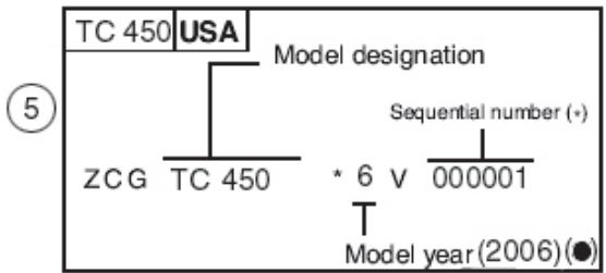
text_image
TC 450 USA Model designation ZCG TC 450 * 6 V 000001 Sequential number (+) T Model year (2006) (●)* Varies-Can be 0 thru 9 or X (check digit for factory use)
⑤
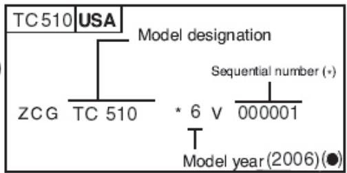
flowchart
graph TD
    A["TC 510 USA"] --> B["Model designation"]
    B --> C["ZCG TC 510"]
    C --> D["* 6 v 000001"]
    D --> E["Sequential number (+)"]
    E --> F["Model year (2006) (●)"]
* Varies-Can be 0 thru 9 or X (check digit for factory use)
⑦
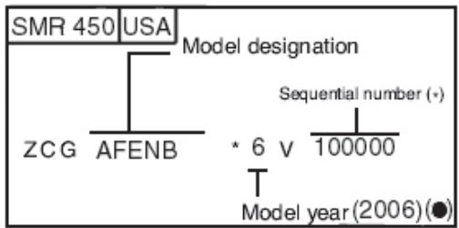
flowchart
graph TD
    A["SMR 450"] --> B["USA"]
    B --> C["Model designation"]
    C --> D["ZCG"]
    C --> E["AFENB"]
    C --> F["* 6 v"]
    C --> G["100000"]
    F --> H["Sequential number (+)"]
    G --> I["Model year (2006) (●)"]
* Varies-Can be 0 thru 9 or X (check digit for factory use)
⑧
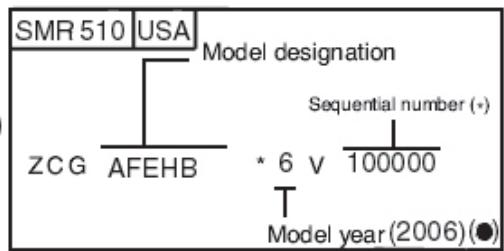
flowchart
graph TD
    A["SMR 510"] --> B["USA"]
    B --> C["ZCG"]
    B --> D["AFEHB"]
    C --> E["Model designation"]
    D --> E
    E --> F["Sequential number (+)"]
    F --> G["* 6 v 100000"]
    G --> H["Model year (2006) (●)"]
* Varies-Can be 0 thru 9 or X (check digit for factory use)
natural_image
Close-up mechanical component with numbered annotation (1) and arrow pointing to a detail area (no readable text or symbols)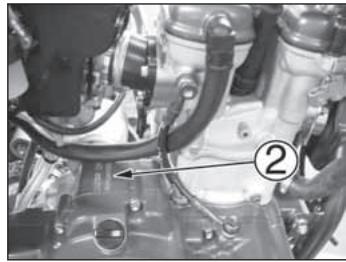
natural_image
Close-up of an automotive engine bay with visible hoses and components (no text or symbols)-
Matricola telaio
-
Matricola motore
-
Frame serial number
-
Engine serial number
-
Matricule cadre
-
Matricule moteur
-
Rahmen Nr.
-
Motor Nr.
-
Matrìcule bastidor
-
Matrìcule motor
UBICAZIONE COMANDI
- Front brake lever
- Throttle grip
- Rear brake control pedal
- Choke (L.H. side)
- Fuel tank filler cap
- R.H. commutator (engine electric start)
- Rear shock absorber spring preload adjustment
- Rear shock absorber compression damper adjustment (low and high damping speeds)
- Rear shock absorber extension damper adjustment
POSITION DES COMMANDES
text_image
Technical diagram of a motorcycle with numbered parts and exploded views, likely for assembly or maintenance instructions.AVVIAMENTO A PEDALE A RICHIESTA (VEDERE PAGINE 262 e 266)
KICK START UPON REQUEST (SEE PAGES 262 and 266)
Type......single cylinder, 4 stroke
Cooling ....liquid
Bore (250)....2.99 in.
Bore (400)....3.6 in.
Bore (450-510)....3.81 in.
Stroke (250) 2.17 in.
Stroke (400-450)......2.39 in.
Stroke (510)......2.67 in.
Displacement (250)....15.22 cu. in.
Displacement (400)......24.37 cu. in.
Displacement (450)......27.39 cu. in.
Displacement (510)....30.56 cu. in.
Compression ratio 12,9:1
Starting (TC) kick start (with automatic decompressor)
Starting (SMR).....electric (with automatic decompressor)
Starting (TE) .....electric and kick start (with automatic decompressor)
TIMING SYSTEM
Type ......double overhead camshaft; 4 valve
Valve clearance (with engine cold)
Intake....0.004 ÷ 0,006 in.
Exhaust 0.006 ÷ 0,008 in.
DONNEES TECHNIQUES
MOTEUR
Type....Dry sump with two oil pump rotor and cartridge filter
IGNITION
Type ....C.D.I. electronic, with variable advance (digital control) Spark plug type ....NGK CR8EB Spark plug gap ....0.027 in.
LUBRIFICATION
Spillo conico (TC)......OBDVR
Spillo conico (TE/SMR)......OBDVT
(Throttle Position Sensor)
Diametro diffusore ......mm 38
Getto massimo 165
Getto minimo....25
Valvola gas....1.0
Spillo conico....52
Tacca fiss. spillo 4a
Type (250....."Keihin" FCR-MX 37 with acceleration pump and throttle position sensor
Tipo (450-510) Keihin" FCR-MX 41 with acceleration pump and throttle position sensor
Venturi diameter (250)......1.46 in.
Venturi diameter (450-510) 1.61 in.
High speed jet (250 175
High speed jet (450-510) 180
Low speed jet (250, TE-SMR 450/510) ....50
Low speed jet (TC 450-510)....55
Starting jet (250)....72
Starting jet (450-510) 85
Starting air jet....0.16 in.
Main air jet 200
Low air jet 100
Floater ......g 11.2
Throttle piston....15
Metering pin (TC)......OBDVR
Metering pin (TE_SMR)......OBDVT
Metering pin slot (TE_SMR)....3rd
Metering pin slot (TC 250)....4th
Metering pin slot (TC 450-510)....5th
Idle mixture adjusting screw (turns)....1+1/2
CARBURETOR (SMR 400)
Type ...... "Mikuni" TMR 38 with acceleration pump and T.P.S. (Throttle Position Sensor)
Venturi diameter 1.50 in.
High speed jet 165
Low speed jet 25
Throttle piston....1.0
Metering pin....52
Metering pin groove....4th
Main nozzle....P4
Idle mixture adjusting screw 2
Acceleration pump jet....30
PRIMARY DRIVE
Drive pinion gear- Clutch ring gear (TC 250) ......Z 20- Z 67
Drive pinion gear- Clutch ring gear (TE 250) ......Z 24- Z 88
Drive pinion gear- Clutch ring gear (450-510)......Z 23- Z 63
Transmission ratio (TC 250) 3,350
Transmission ratio (TE 250)....3,666
Transmission ratio(400-450-510)....2,739
CARBURATEUR (250-450-510)
Gicleur principal (250)....175
Gicleur principal (450-510) 180
Gicleur ralenti (250, TE-SMR 450/510) ....50
Gicleur ralenti (TC 450-510) ....55
Gicleur de starter (250)....72
Gicleur de starter (450-510)....85
Gliceur air starter ....mm 4
Type ......oil bath multiple disc clutch, hydraulic control
TRANSMISSION
Type......constant mesh gear type
Transmission ratio (TE-SMR)
1st gear....2,000 (z 28/14)
2nd gear....1,611 (z 29/18)
3rd gear 1,333 (24/18)
Transmission ratio (TC)
1st gear....1,866 (z 28/15)
2nd gear (250) 1,529 (z 26/17)
2nd gear (450-510)....1,444 (z 26/17)
Transmission ratio (TE 250-450)....3,846
Transmission ratio (TC 450-510). 3,571
Transmission ratio (TC 250)....4,166
Transmission ratio (TC 510).... 3,357
Transmission ratio (SMR 400-450-510) 3,000
EMBRAYAGE
1st gear (TE 250) ......28,205
1st gear (TE 450) ......21,070
1st gear (TE 510)....19,565
1st gear (TC 250) ......26,055
1st gear (TC 450) 18,261
1st gear (TC 510)....17,159
1st gear (SMR 400-450-510) ...... 16,435
2nd gear (TE 250) ......22,721
2nd gear (TE 450) 16,973
2nd gear (TE 510) 15,761
2nd gear (TC 250) ......21,348
2nd gear (TC 450) 14,130
2nd gear (TC 510) ......13,283
2nd gear (SMR 400-450-510) ...... 13,239
3rd gear (TE 250) 18,803
3rd gear (TE 450) 14,047
3rd gear (TE 510) ......13,043
3rd gear (TC 250) ......17,631
3rd gear (TC 450) ......12,357
3rd gear (TC 510) ......11,616
3rd gear (SMR 400-450-510)....10,956
RAPPORTS TOTAUX DE TRANSMISSION
4th gear (TE 250) ......15,329
4th gear (TE 450) ......11,451
4th gear (TE 510)....10,633
4th gear (TC 250)....15,172
4th gear (TC 450) ......10,633
4th gear (TC 510) 9,995
4th gear (SMR 400-450-510)....8,932
5th gear (TE 250) ......12,974
5th gear (TE 450) 9,692
5th gear (TE 510) 9,000
5th gear (TC 250) ......13,324
5th gear (TC 450) 9,338
5th gear (TC 510) 8,778
5th gear (SMR 400-450-510) .....7,560
6th gear (TE 250) ......11,491
6th gear (TE 450) 8,584
6th gear (TE 510) ......7,971
6th gear (SMR 400-450-510) ......6,696
Anteriore (SMR)......SANREMO in lega leggera: 3,50x17"
Posteriore (TE) ......TAKASAGO “Excel” in lega leggera: 2,15x18"
Posteriore (TC) ......TAKASAGO “Excel” in lega leggera: 1,85x19"(250); 2,15x19"(450-510)
Posteriore (SMR) .....SANREMO in lega leggera: 4,25x17"
FRAME
Type ....Single-beam with circular steel tubes; light alloy rear frame
FRONT SUSPENSION
Type .... "Upside-Down" telescopic hydraulic front fork with advanced axle (adjustable in compression and rebound stroke); stanchions tubes ø 1.77 in. (250) and ø 1.97 in. (400-450-510) Legs axis stroke(TE, TC) 11.8 in.; (SMR) 9.84 in.
REAR SUSPENSION
Type....progressive with hydraulic single shock absorber
Wheel stroke (TE) 12.6 in.
Wheel stroke (TC)....12.8 in.
Wheel stroke (SMR)....1 1 .4 in.
FRONT BRAKE
Type....fixed disc 10.24 in. dia (TE, TC). floating disc 12.6 in. dia (SMR)
with hydraulic control; floating caliper (TE, TC) or fixed caliper (SMR)
REAR BRAKE
Type.... floating disc, ∅ 9.45 in. with hydraulic control and floating caliper
RIMS
Front (TE, TC) TAKASAGO "Excel" in light alloy: 1.6x21"
Front (SMR)..SANREMO in light alloy: 3,50x17"
Rear (TE)......TAKASAGO “Excel” in light alloy: 2,15x18”
Rear (TC) ..... TAKASAGO "Excel" in light alloy: 1,85x19"(250); 2,15x19"(450-510)
Rear (SMR) ..SANREMO in light alloy: 4,25x17"
CADRE
Radhub (SMR)....290 mm
VORDERRADBREMSE
Delantera (SMR)...SANREMO in liga ligera: 3,50x17"
Trasera (TE) ...TAKASAGO “Excel” in liga ligera: 2,15x18”
a freddo (anteriore TC)....0,9÷1,0 Kg/cm2
a freddo (anteriore TE)....0,9..1,0 Kg/cm2
(●) a freddo (posteriore TE)....1,0 Kg/cm2
Cold tire pressure (front TC)....0,9,0 Kg/cm2; 12.84.2 psi
Cold tire pressure (rear TC).....0,8,9 Kg/cm2; 11.42.8 psi
Cold tire pressure (front TE)....0,9,0 Kg/cm2; 12.84.2 psi
Cold tire pressure (rear TE).....0,8,9 Kg/cm2; 11.42.8 psi
(●) Cold tire pressure (front TE)......1,1 Kg/cm2; 15.6 psi
(●) Cold tire pressure (rear TE)......1,0 Kg/cm2; 14.2 psi
(*)Cold tire pressure 1,4 kg/cm ^2 (front SMR).... 20 psi
(●)Cold tire pressure 1,8 kg/cm ^2 rider only (front SMR).... 25,6 psi
(●)Cold tire pressure 2,0 kg/cm ^2 rider and (front SMR)....28,4 psi passenger
(*)Cold tire pressure 1,6kg/cm ^2 (rear SMR) 22.7 psi
(●)Cold tire pressure (rear SMR).... 2,0 kg/cm ^2 rider only 28.4 psi
(●)Cold tire (rear SMR).... 2,2 kg/cm ^2 rider and passenger 31,3 psi
(●) Road use
(*) in case of racing use
PNEUS
Avant
(TE) ......Michelin ENDURO COMP. 3 ou
Pirelli MT 83 Scorpion;ou Dunlop 54R-D907;90/90x21"
(TC) Pirelli 51R-MT 32A;
80/100 x 21"
(SMR)....Pirelli MTR 21 DRAGON-EVO; 120/70-17"
Arrière
(TE)......Michelin ENDURO COMP. 3 ou Pirelli MT 83
Scorpion ou Dunlop 70R-D907; 120/90x18" (250); 140/80x18" (450 - 510)
(TC)......Pirelli NHS (62) MT 32; 100/90x19" (250); 110/90x19" (450 - 510)
(SMR) ......Pirelli MTR 22 DRAGON-EVO; 150/60x17"
froid (avant TE) ......0,9.-1,0 Kg/cm2
(trasero TE). 1,0 Kg/cm2e.
DIMENSION, WEIGHT, CAPACITY
Wheelbase (TC 250)....58.46 in.
Wheelbase (TC 450-510)....57.95
Wheelbase (TE 250)....57.87 in.
Wheelbase (TE 450-510)....57.95 in.
Wheelbase (SMR 400-450-510).....58.86 in.
Overall length (TC 250)......86.61 in.
Overall length (TC 450-510) ......85.51 in.
Overall length (TE 250)......88.19 in.
Overall length (TE 450-510)......87.1 in.
Overall length (SMR 400-450-510)......86.22 in.
Overall width (TC)....32.28 in.
Overall width (TE-SMR)....33.07 in.
Overall height (TC 250)....50 in.
Overall height (TC 450-510) .....50.39 in.
Overall height (TE 250)....50.39 in.
Overall height (TE 450-510)....50.79 in.
Overall height (SMR 400-450-510)......49.21 in.
Saddle height (TC 250)....38 in.
Saddle height (TC 450-510) ......38.58 in.
Saddle height (TE 250)....38 in.
Saddle height (TE 450-510)......38.58 in.
Saddle height (SMR 400-450-510)......36.02 in.
Minimum ground clearance (TC 250) ..13.19 in.
Minimum ground clearance (TC 450-510) 13.38 in.
Minimum ground clearance (TE 250) 13.19 in.
Minimum ground clearance (TE 450-510) 13.38 in.
Minimum ground clearance
((SMR 400-450-510)....10.63 in
DIMENSIONS, POIDS, CAPACITE
Empattement (TC 250) ......mm 1485
Empattement (TC 450-510)......mm 1472
Empattement (TE 250) ......mm 1470
Empattement (TE 450-510) ......mm 1472
Empattement (SMR 400-450-510) .....mm 1495
Kerb weight, without fuel
(TC 250)....lb 230.8
Kerb weight, without fuel
(TC 450) ... lb 242.5
Kerb weight, without fuel
(TC 510) lb 244.7
Kerb weight, without fuel
(TE 250)....lb 244.7
Kerb weight, without fuel
(TE 450).... lb 256.4
Kerbweight, without fuel
(TE 510) .... Ib 257.5
Kerb weight, without fuel ....
(SMR 400) lb 268.3
Kerbweight, without fuel ....
(SMR 450) .... Ib 269.4
Kerb weight, without fuel ....
(SMR 510) .... Ib 270.5
Fuel tank capacity, (1.58 Imp. Quarts, 1.9 US qt. reserve included) ....Imp. Gall. 2
US Gall. 2.4
Coolant capacity......Imp. Quarts 2.0÷2.4
Transmission oil
Oil and oil filter replacement ....
Imp. Quarts 1.5
U.S. Quarts 1.8
Oil replacement ....Imp. Quarts 1.3
U.S. Quarts 1.6
Poids en orde de marche, sans carburant
(TC 250) ......kg 104,7
Poids en orde de marche, sans carburant
(TC 450) ......kg 110
Poids en orde de marche, sans carburant
(TC 510) ......kg 111
Poids en orde de marche, sans carburant
(TE 250) ......kg 111
Poids en orde de marche, sans carburant
(TE 450) ......kg 116,3
Poids en orde de marche, sans carburant
(TE 510) ....kg kg 116,8
Poids en orde de marche, sans carburant
(SMR 400) ......kg 121,7
Poids en orde de marche, sans carburant
(SMR 450) ....kg 122,2
Poids en orde de marche, sans carburant
(SMR 510) ... kg 122,7
The cock, placed on the left side, has three positions:
OFF - Closed; the fuel does not come out;
ON - Open; the fuel flows from the main flux;
RES - Reserve; the fuel flows from the reserve flux.
When difficulties in flowing arise while running, set the right cock lever on RES position.
After filling up, take the cock on ON position again.
WARNING\*: Be careful not to touch the hot engine while operating the fuel valve.
A fuel filter is incorporated in the fuel valves. Accumulation of dirt in the filter will restrict the flow of the fuel to the carburetor. Therefore, the fuel filter should be serviced periodically. To service:
1 - Unscrew the filler cap (1) on the fuel tank then place the fuel cock (2) on OFF position;
2 - remove the fuel hose (3) from the carburetor and insert the hose in a vessel;
COMMANDES
ROBINETS CARBURANT
3 - place the fuel cock (2) on ON position in order to eliminate the fuel from the tank;
4 - Remove the fuel valve by removing the screws. Wash the fuel screen filter in cleaning solvent.
5 - Reassemble the fuel valve in the reverse order of removal. Turn the fuel valve "ON" and check for leaks.
SIDESTAND A sidestand (1) is supplied with every motorcycle.
WARNING\*: The stand is designed to support the weight of the MOTORCYCLE ONLY. Do not sit on the motorcycle using the stand for support as this could cause structural failure to the stand and could cause serious bodily injury.
Periodically check the side stand (see “Periodical maintenance card”); check that the springs are not damaged and that the side stand freely moves. If the side stand is noisy, lubricate the fastening pivot (A).
natural_image
Mechanical assembly diagram showing a chain link and gear mechanism (no text or symbols)CARBURANTE
Recommended fuel: premium grade unleaded fuel. (R.O.N. 98).
Note*: Do not continue operation if the engine pings or knocks. The engine will be damaged and could seize.
WARNING*: If "knocking" or "pinging" occurs, try a different brand of gasoline or higher octane grade.
WARNING*: Gasoline is extremely flammable and can be explosive under certain conditions. Always stop the engine and do not smoke or allow flames or sparks in the area where the motorcycle is refueled or gasoline is stored.
WARNING*: Do not overfill the tank. After refueling, make sure the tank cap (1) is closed securely.
CARBURANT
text_image
1 HuaqatmaCARBURETOR CHOKE The starter knob, located on the left side of the carburetor, is used to enrich the mixture during the engine start. Pull out the knob to open the starter, and pull the lever upwards to close it.
The carburetor is equipped with two knobs:
1) BLACK KNOB: COLD start (°)
2) RED KNOB: WARM start (°)
text_image
Technical diagram of engine components with numbered labels pointing to specific parts(°) Ver pagina. 85
STRUMENTO DIGITALE, SPIE (TE-SMR)
DIGITAL INSTRUMENT, WARNING LIGHTS (TE-SMR)
The motorcycle is equipped with a digital instrument; on the instrument are located 4 warning lights too: high beam, lights (with display lighting), blinkers and neutral.
1- BLUE warning light "HIGH BEAM"
2- GREEN warning light "LIGHTS"
3- GREEN warning light "BLINKERS"
4- GREEN warning light "NEUTRAL"
NOTES
- After the engine starting, for the first 2 seconds, the instrument shows the version of the checking SW; after the check, the instrument shows the last planned function.
- When the motorcycle engine is OFF, the instrument doesn't also show its functions.
- To select the instrument functions and to set to zero the functions, use the SCROLL knob (A).
INSTRUMENT DIGITAL, VOYANTS (TE-SMR)
- The instrument functions are the following, as shown below.
1- SPEED / ODO (figure 1)
2- SPEED / H (figure 2)
3- SPEED / CLOCK (figure 3)
4- SPEED / TRIP 1 (figure 4)
5- SPEED / STP 1 (figure 5)
6- SPEED / AVS 1 (figure 6)
7- SPEED / SPEED MAX (figure 7)
8- SPEED / TRIP 2 (figure 8)
9- SPEED / TRP 2 / CLOCK (figure 9)
10- SPÉED / RPM (engine r.p.m. numerical value) (figure 10)
1- SPEED / ODO (figure 1)
NOTE
The RPM function, shown on the vertical LED indicator, is ALWAYS on.
natural_image
Close-up of a motorcycle front panel with display and control buttons (no readable text or symbols)1- SPEED (kmh o mph) / ODO / RPM (figura 1)
- SPEED: motorcycle speed-maximum value: 299 kmh or 299 mph;
- ODO: odometer- maximum value: 99999 km;
- RPM: engine r.p.m. shown on the vertical LED indicator.
To replace kilometers with miles or miles with kilometers proceed as follows:
1) set to figure 1, stop the engine and push the knob SCROLL (A).
2) start the engine while pushing for 3 seconds the knob SCROLL (A).
After the kilometers-miles or miles-kilometers setting operation, for 3 seconds, “SET” and miles/mph or km/kmh will be on.
NOTE
After the previously described operation, the ODO setting will be convert and all the others data will be reseted (the H Counter is unchanged).
1- SPEED (kmh ou mph) / ODO / RPM (figure 1)
- SPEED: motorcycle speedmaximum
value: 299 kmh or 299 mph; - H: shows the running hours of the engine (data are saved in permanent memory every 10 minutes)- Maximum value: 9999:59;
- RPM: engine r.p.m. shown on the vertical LED indicator.
3- SPEED / CLOCK / RPM (figure 3)
- SPEED: motorcycle speedmaximum value: 299 kmh or 299 mph;
- CLOCK: clock- Reading from 0:00 to 23:59:59 (the data will be lost after battery detachment).
To reset the clock, push the knob SCROLL (A) for more than 3 seconds in order to increase the hours; release the knob and then, after 3 seconds, it is possible to increase the minutes; - RPM: engine r.p.m. shown on the vertical LED indicator.
2- SPEED / H / RPM (figure 2)
- SPEED: motorcycle speedmaximum value: 299 kmh or 299 mph;
- TRIP 1: distance- maximum value: 999.9 km (the data will be lost after battery detachment). If the STP 1 will be set to zero, the functions TRIP 1 and AVS 1 will be set to zero too.
- RPM: engine r.p.m. shown on the vertical LED indicator.
The function TRIP 1 is ON unitedly with the function STP 1 (\*).
(*): see figure 5
4- SPEED / TRIP 1 / RPM (figure 4)
- SPEED: motorcycle speedmaximum value: 299 kmh or 299 mph;
- STP 1: miles/kilometers covered time- Reading from 0:00 to 23:59:59 (the data will be lost after battery detachment).
To activate the function STP 1, push the knob SCROLL (A) for more than 3 seconds.
- 1st step: function ON;
- 2nd step: stop to the counters;
- 3rd step: STP 1 zero-setting; TRIP 1 and AVS 1 data zero-setting;
- 4th step: function ON;
- 5th step: stop to the counters; and so following
NOTE
STP 1 data+TRIP 1 data=AVS 1 (*).
- RPM: engine r.p.m. shown on the vertical LED indicator.
(*): see figure 6
5- SPEED / STP 1 / RPM (figure 5)
- SPEED: motorcycle speedmaximum value: 299 kmh or 299 mph;
- AVS 1: shows the covered average speed of the motorcycle, according with a distance (TRIP 1) and a miles/kilometers covered time (STP 1) (the data will be lost after battery detachment).
NOTE
If the STP 1 will be set to zero, the TRIP 1 and AVS 1 functions will be set to zero too.
- RPM: engine r.p.m. shown on the vertical LED indicator.
6- SPEED / AVS 1 / RPM (figure 6)
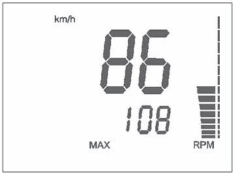
- SPEED: motorcycle speedmaximum value: 299 kmh or 299 mph; - V MAX: shows the motorcycle MAXIMUM speed (reached MAX speed), kmh or mph. Maximum value: 299 kmh or 299 mph. To set to zero V MAX, push the knob SCROLL (A) for more than 3 seconds; - RPM: engine r.p.m. shown on the vertical LED indicator.
8- SPEED / TRIP 2 / RPM (figure 8)
- SPEED: motorcycle speedmaximum value: 299 kmh or 299 mph; - TRIP 2: distance- maximum value: 999, 9 km / miles (the data will be lost after battery detachment). To set to zero TRIP 2, push the knob SCROLL (A) for more than 3 seconds; - RPM: engine r.p.m. shown on the vertical LED indicator.
7- SPEED / V MAX / RPM (figure 7)
text_image
A E N E +57
text_image
km/h 86 108 MAX RPM8
text_image
km/h 48 TRP 48.89 2 RPM9- TRP 2 / CLOCK / RPM (figura 9)
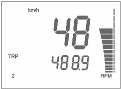
- TRIP 2: distance- Max value: 999.9 km / miles (the data will be lost after battery detachment).
To set to zero TRIP 2, push the knob SCROLL (A) for more than 3 seconds; - CLOCK: clock- Reading from 0:00 to 23:59:59 (the data will be lost after battery detachment). To reset the clock, push the knob SCROLL (A) for more than 3 seconds in order to increase the hours; release the knob then, after 3 seconds, it is possible to increase the minutes;
- RPM: engine r.p.m. shown on the vertical LED indicator.
10- SPEED /RPM (engine r.p.m. numerical value) (figure 10)
- SPEED: motorcycle speedmaximum value: 299 kmh or 299 mph;
- RPM: engine r.p.m.; both vertical LED indicator and numerical value are on.
9- TRP 2 / CLOCK / RPM (figure 9)
The throttle knob (1), is located on the right hand side of the handlebar. The position of the throttle control can be adjusted by loosening the two fastenig screws (*).
POIGNEE DES GAZ
Do not forget to tighten the screws (A) after the adjustment.
ATTENTION
The brake control lever (2) is located on the right hand side of the handlebar. The position of the throttle control can be adjusted by loosening the two fastenig screws (*).
COMMANDE FREIN AVANT
Do not forget to tighten the screws (B) after the adjustment.
ATTENTION
The motorcycle is equipped with a steering lock (1) on the R.H. side of the steering head tube. To lock it, proceed as follows: turn the handlebar leftwards, place the key in lock and turn counterclockwise. Push the key inwards (if necessary, turn to and from). Turn the key clockwise and remove it from the lock. To unlock the steering lock, reverse the above procedure.
BLOC DE DIRECTION
(TE-SMR)
natural_image
Close-up of mechanical components with a numbered label (1) pointing to a specific part, no readable text or symbols present.COMMUTATORE DESTRO SUL MANU-BRIO
(TE-SMR)
The right commutator has the following controls:
1) Engine start button
3) Engine start - stop switch
L.H. HANDLEBAR COMMUTATOR (TE-SMR)
CONTROLS:
1) D High beam flash (self cancel-ling)
2) D Selection control High beam

Selection control Low beam
3) Left turn signals (automatic return)
→ Right turn signals (automatic return)
To deactivate the turn signals, press the control lever after its returning to center.
4) Warning horn
5) Lighting control of Low beams and High beam

Lighting control of Position light
• Off
COMMUTATEUR DROIT SUR LE GUIDON
(TE-SMR)
text_image
Labeled diagram of a bicycle steering wheel showing key parts: handle, grip, and lever with numbered annotations.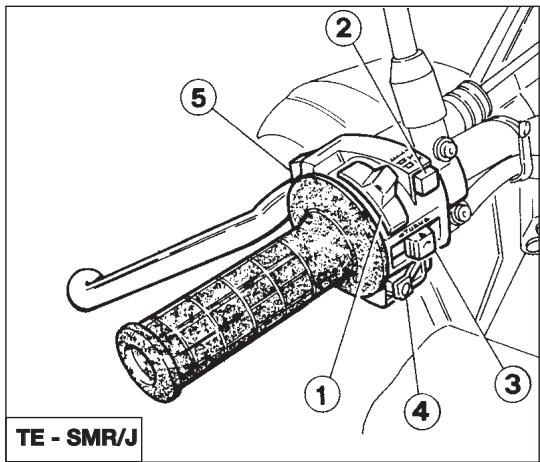
text_image
TE - SMR/J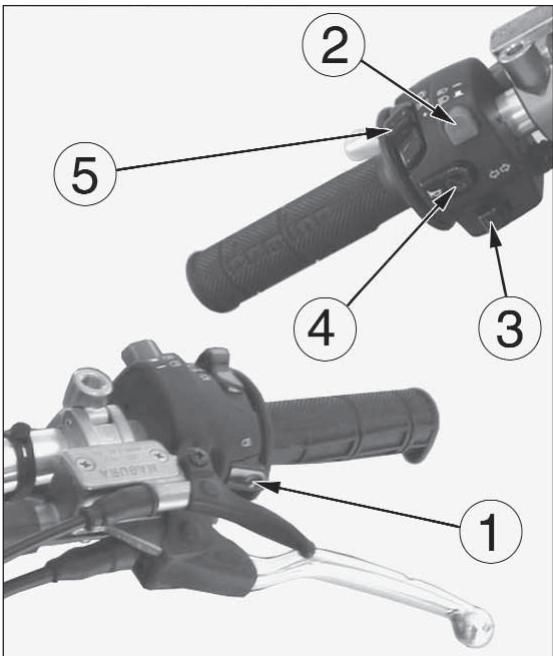
text_image
Labeled diagram of a bicycle brake lever mechanism showing five numbered parts with Chinese annotationsPULSANTE ARRESTO MOTORE (TC)
On the left side of the handlebar, near the clutch control, is located the engine stop button.
BOUTON D'ARRET MOTEUR (TC)
The hydraulic clutch control lever is located on the left-hand side of the handlebar and is protected against dirt with a rubber guard. The clutch control position on the handlebar can be adjusted by loosening the lower fastening screw (A).
COMMANDE DE L'EMBRAYAGE
Do not forget to tighten the screw after the adjustment.
ATTENTION
The rear brake control (1) is placed on the right-hand side of the motorcycle. On models TE and SMR as stop switch, during the braking action, causes the rear light to come on.
natural_image
Mechanical assembly diagram showing motor components and wiring (no text or symbols visible)COMANDO CAMBIO
The lever (1) is placed on the left-hand side of the engine. The operator must release the lever after each gear change to allow it to return to its central position before another gear change can be made.
Neutral position (N) is between first (low) and second gears. First gear is engaged by pushing the lever downwards; all the other gears are engaged, by pushing the lever upwards.
The position of the gear shift lever on the shaft can be varied by:
- loosening screw;
- pulling lever out;
- placing lever in new position on the shaft when the operation is over tighten the screw and then tightening the screw.
COMMANDE DU CHANGEMENT DE VITESSES
CAUTION*: Do not shift gears without disengaging the clutch and closing the throttle. The engine could be damaged by overspeed and shock.
WARNING*: Do not downshift when traveling at a speed that would force the engine to over-rev in the next lower gear, or cause the rear wheel to lose traction.
Before each ride, to prevent accidents or failures during ride, make sure to go through following list.
1. Check all fluids
A. Engine-transmission oil level
B. fuel level
C. coolant level
Make sure all caps are properly adjusted.
WARNING\*: Don't remove radiator cap when hot!
2. Check all controls
A. Throttle handgrip
B. Clutch lever
Make sure cables are not damaged and turn smoothly.
3. Check brakes
Look for brake fluid leaks and worn hoses.
Check for proper functioning.
4. Check suspensions
Compress fork and rear suspensions. Look for oil leaks and ensure proper functioning.
MODE D'EMPLOI DE LA MOTO
CONTROLES PRELIMINAIRES
ATTENTION!
Check spokes and look for worn bearings.
Check rims and tyres.
Check tyre pressure.
- Check chain rollers and sprockets
Check wear on chain rollers and sprockets
Ensure chain is correctly adjusted and lubricated.
- Check air filter and intake system
Check that air filter is clean
Check all rubber connections and clamps.
- Check exhaust system
Check hook up, look for cracks
Check muffler.
- Check torque
A. Spark plug
B. Cylinder-head nuts
C. General check of torque
- Check steering action
Check bearing play.
- Check the electric system (TE-SMR). Start the engine and check that the front and rear lamps, the stop light, the turn signals the cluster warning lights and the horn are working correctly.
WARNING*: Failure to perform these checks every day before you ride may result in serous damage or a severe accident.
- Contrôle des roues
(TE-SMR, SMR 400 excluded)
With cold engine, as after a prolonged inactivity of the motorcycle or in presence of a low external temperature, proceed as follows:
1) set fuel cock in ON position;
2) shift gear pedal (1) in neutral position;
3) pull the BLACK starter knob (2);
4) turn twice completely the throttle control grip (3).
5) pull the clutch control lever (4).
6) press the engine start-stop switch (6) then the start button (7). Release the clutch control lever (4).
natural_image
Close-up of a mechanical engine component with hoses and valve (no visible text or symbols)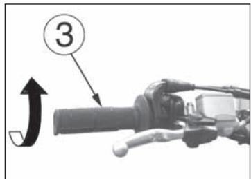
text_image
3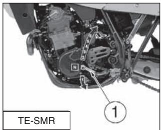
text_image
TE-SMR ①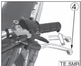
natural_image
Mechanical component with lever and handle assembly, labeled TE_SMR (no readable text or symbols beyond label)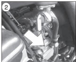
natural_image
Close-up of a mechanical component with no visible text or symbols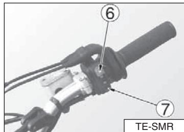
text_image
⑥ ⑦ TE-SMR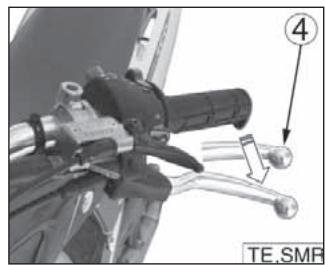
natural_image
Mechanical component with lever and wrench, labeled (4), no readable text or symbols beyond labelIn case of difficult starting with warm engine, or after an upset, proceed as follows:
1) shift gear pedal (1) in neutral position;
2) pull the RED starter knob (2);
3) pull the clutch control lever (3);
natural_image
Mechanical assembly diagram showing a valve mechanism with no visible text or symbols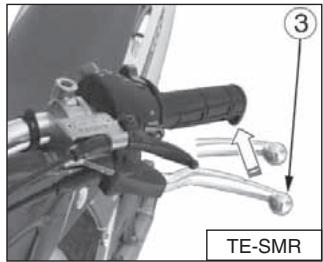
text_image
TE-SMRnatural_image
Close-up of a mechanical lever handle and lever with a labeled component (no readable text or symbols)With cold engine, as after a prolonged inactivity of the motorcycle or in presence of a low external temperature, proceed as follows:
1) set fuel cock (1) on ON position;
2) shift the transmission lever (A) into neutral position;
3) pull the black starter knob (2);
4) turn twice completely the throttle control grip (3);
5) while maintaining slowly open the throttle control grip;
6) pull the clutch control lever;
7) press the engine start-stop switch (B) then the start button (1). Release the clutch lever.
IN CASO DI AVVIAMENTO A CALDO, NON EFFETTUARE LE OPERAZIONI 3 E 4.
WITH WARM ENGINE, DO NOT CARRY-OUT ITEMS no. 3 AND 4.
DÉMARRAGE DU MOTEUR (SMR 400)
natural_image
Close-up of a mechanical component with no visible text or symbols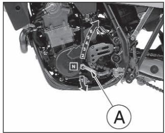
text_image
Technical diagram of a mechanical assembly with labeled parts and annotation A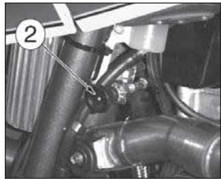
natural_image
Close-up mechanical assembly showing a pipe joint and valve (no visible text or symbols)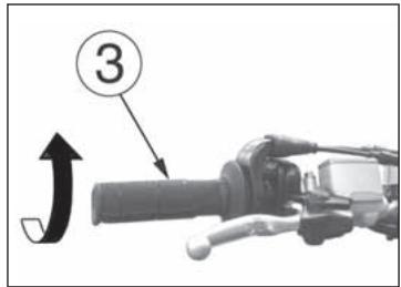
text_image
③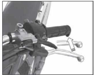
natural_image
Close-up of a mechanical lever mechanism with a tool and directional arrow (no text or symbols visible)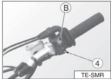
text_image
B 4 TE-SMR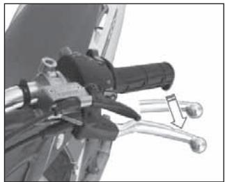
natural_image
Close-up of a mechanical lever mechanism with no visible text or symbolsStarting decompressor
Though the engine is provided with an automatic decompressor, can be necessary, in some cases (carburetor flooding or starting difficulties due to a battery inadequate charge), to use the manual starting decompressor on the L.H. side of the handlebar. In these cases, pull the lever (5) whilst simultaneously pressing the starter button, release the lever (5) keeping the button pressed and afterwards release the latter as well.
In order to adjust the lever decompressor free play (approximately 3 mm-0.12 in.), the lever holder is provided with the adjuster (6); the adjustment can be also effected with the tightener (7) on the R.H. side of the engine (use this tightener if it is not possible to obtain the correct free play with the adjuster on the handlebar).
natural_image
Close-up mechanical assembly showing hoses and components in a vehicle (no visible text or symbols)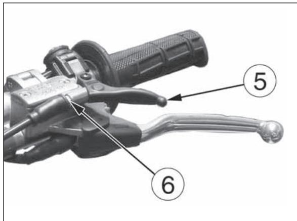
text_image
5 6AVVIAMENTO DEL MOTORE (TC)
1) set fuel cock on ON position;
2) shift gear pedal (1) in neutral position;
3) pull the starter knob (BLACK knob 2 for cold starting *, RED knob 3 for warm starting);
4) lower the starter pedal (4) until a certain resistance is noticed (piston at T.D.C.);
5) pull the lever (5) and lower further, by a limited stroke, the pedal until the abovementioned resistance is overcome (surpassing of T.D.C.);
DÉMARRAGE DU MOTEUR (TC)
*: after a prolonged inactivity of the motorcycle or in presence of a low external temperature.
natural_image
Close-up of a car engine bay with hoses and a valve, no visible text or symbols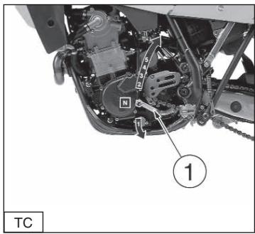
text_image
1 TC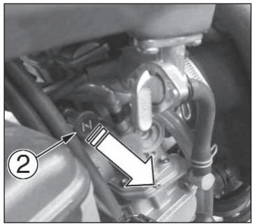
natural_image
Close-up of a mechanical assembly with hoses and components, no visible text or symbols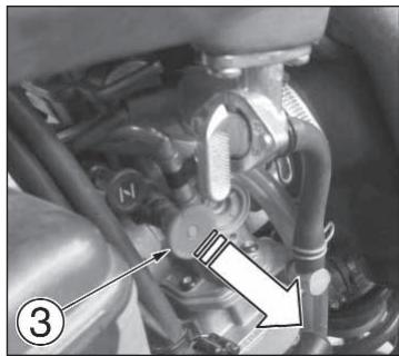
natural_image
Close-up of a mechanical engine component with hoses and springs (no visible text or symbols)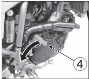
natural_image
Close-up mechanical assembly showing internal components and a numbered label (4), no readable text or symbols present.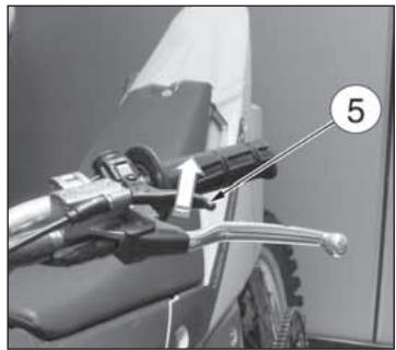
natural_image
Close-up of a motorcycle's front wheel and hand lever assembly (no visible text or symbols)natural_image
Mechanical assembly diagram showing engine components and a numbered annotation (4), no readable text or symbols present.6) at this point, release the lever (5) and the pedal (4);
7) in the case of COLD STARTING, completely rotate the throttle (6) twice (in the case of warm starting DO NOT carry out this operation);
8) COMPLETELY lower the pedal (4) until the engine starts.
WARM STARTING: BEFORE MOTORCYCLE STARTING, PRESS RED CHOKE KNOB (3) ON CARBURETOR TOWARD THE INSIDE IN ORDER TO DEACTIVATE THE STARTING DEVICE.
In case the engine does not start, repeat this procedure.
natural_image
Close-up of a motorcycle's handle and lever mechanism, labeled with number 5 (no text or symbols on the device itself)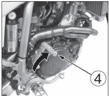
natural_image
Mechanical assembly diagram showing engine components and a numbered label (4), no readable text or symbols present.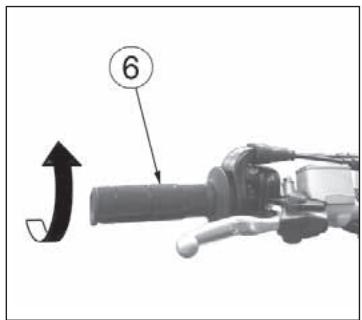
text_image
6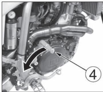
natural_image
Mechanical assembly diagram showing engine components with no visible text or symbols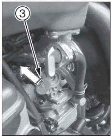
text_image
Technical diagram of an engine component with numbered annotation pointing to a specific partNOTA IMPORTANTE IN CASO DI AVVIAMENTO A FREDDO A BASSE TEMPERATURE
It is recommended to briefly warm-up the engine at idle until, after having disengaged the starter, there is a normal response from the engine when opening the throttle.
In this way the oil can reach all the surfaces needing lubrication and the coolant will reach the necessary temperature for correct engine function.
Avoid overheating the engine.
IMPORTANT
Never accelerate the engine after a cold start.
WARNING*: Exhaust contains poisonous carbon monoxide gas. Never run the engine in a closed garage or in a confined area.
In the case of using a kick-starter, keep in mind the undermentioned note.
Kick start pedal
WARNING*: This high performance motorcycle can some times «kick back» strongly when you are starting it.
Do not attempt to start this motorcycle unless you are wearing high top heavy sided riding boots. You could seriously hurt you leg if the kickstarter kicked back and your foot slipped.
NOTE IMPORTANT DANS LE CAS DE LA MISE EN ROUTE A' FROID ET TEMPERATURES BAS
natural_image
Close-up of a motorcycle's internal engine and drivetrain components (no visible text or symbols)ARRESTO DEL MOTOCICLO E DEL MOTORE
STOPPING THE MOTORCYCLE AND THE ENGINE
- Close the throttle (1) completely so that the engine will help slow down the motorcycle.
- For normal braking, gradually apply both front and rear brakes while down shifting (for maximum deceleration, apply the front and rear brakes firmly).
- When stopped, pull the clutch lever and shift gear lever (2) in neutral position.
- Press the engine stop RED button (3).
- Close the fuel cock (4).
ARRET DU MOTOCYCLE ET DU MOTEUR
WARNING*: Independent use of the front or rear brake maybe advantageous under certain conditions. Use caution when using the front brake, especially on slippery surfaces. Improper use of the brakes can lead to a serious crash.
natural_image
Close-up of a bicycle brake lever mechanism with a hand and two curved levers, no visible text or symbols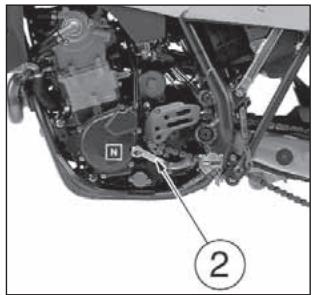
natural_image
Close-up of a mechanical assembly with labeled parts (no readable text or symbols)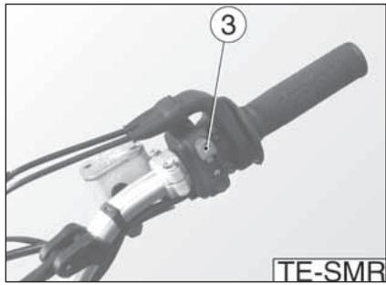
text_image
③ TE-SMR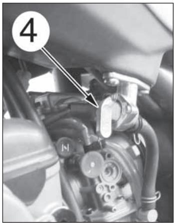
text_image
4natural_image
Close-up of a mechanical lever handle and grip with labeled component (no text or symbols beyond label)WARNING*: In the event of stuck throttle or other malfunction which causes the engine to run uncontrollably, IMMEDIATELY depress the engine stop button and hold it down. Control the motorcycle by normal use of the brakes and steering while holding the engine stop button down.
Before using the motorcycle for sporting activities run in the engine for two hours at least to increase the life and the performance of the engine.
During the first half-hour of driving we advise keeping a low speed and avoiding sudden accelerations. Never open the throttle fully.
Change the oil and carry out all the necessary maintenance operations. After the first half-hour of driving, lightly increase the rev number, but never run the engine at full throttle. Never keep low speeds when the high gears are inserted. Slowly drive the motorcycle for two hours before using it for sporting activities.
RODAGE
CHECKS WHILE RUNNING IN
- SPOKE TENSION OF WHEELS (see page 224);
- TIGHTENING OF WHEELS (see page 254-258);
- FORK PIN TIGHTENING (see page 254);
- CHAIN ADJUSTMENT (see page 150);
- STEERING BEARING PLAY (see page 120);
- HANDLEBAR TIGHTENING (see page 254);
- ENGINE GRIP TO FRAME (see page 254);
- SUCTION FITTING GRIP (see page 252);
- HEAD AND CYLINDER NUTS GRIP (see page 252)
- OFTEN CHECK THE BATTERY CHARGE CONDITION (see page 236.)
CONTROLES PENDANT LE RODAGE
- CONTROLE DE LA TENSION DES RAYONS DES ROUES (224);
- CONTROLE DU SERRAGE ROUES (se reporter à la page 254-258);
- CONTROLE DU SERRAGE GOUPILLE FOURCHE (se reporter à la page 254);
- CONTROLE DU REGLAGE CHAINE (se reporter à la page 150);
- CONTROLE DU JEU DES ROULEMENTS DE LA DIRECTION (se reporter à la page 120);
- CONTROLE DU SERRAGE DU GUIDON (se reporter à la page 254);
- CONTROLE DU SERRAGE DU MOTEUR SUR LE CADRE (se reporter à la page 254);
- CONTROLE DU SERRAGE DU RACCORD D'ASPIRATION (se reporter à la page 252);
- CONTROLE DU SERRAGE ECROUS, TETE ET CYLINDRE (se reporter à la page 252);
- CONTRÔLER FRÉQUENTEMENT L'ÉTAT DE CHARGE DE LA BATTERIE (VOIR PAGE 236)
KONTROLLEN WÄHREND DES EINFAHRENS
CHECKING THE OIL LEVEL By keeping the motorcycle on a flat surface, in vertical position, remove the control screw (1) and check the oil should just barely escape from the hole on the R.H. cover. To fill up, remove the filler cap (2).
CONTROLE DU NIVEAU DE L'HUILE
Note*: Have this operation made with warmed-up engine.
WARNING*: Be careful not to touch hot engine oil.
text_image
Technical diagram of a motorcycle engine showing labeled components with arrows and numbered annotationsSOSTITUZIONE OLIO MOTORE E PULIZIA- SOSTITUZIONE FILTRI METALLICI ED A CARTUCCIA
ENGINE OIL REPLACEMENT AND BAG FILTERS-FILTER CARTRIDGE CLEANING OR REPLACEMENT
WARNING\*: Be careful not to touch hot engine oil.
Drain the oil with WARM ENGINE; proceed as follows:
- remove oil filler cap (1);
- remove the engine guard (A);
● place an oil drain pan under the engine block; - remove the oil drain cap (2), drain the used oil completely then clean the magneto on the cap;
VIDANGE D'HUILE MOTEUR ET NETTOYAGE- REEMPLACEMENT DES FILTRES A TAMIS ET DE LA CARTOUCHE FILTRANTE
text_image
Technical diagram of a vehicle's internal components with numbered labels pointing to parts A, 2, and 3.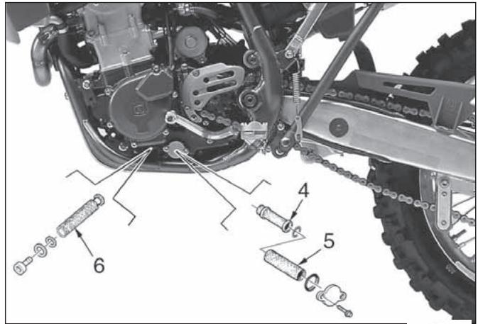
text_image
Technical diagram of a vehicle's internal components with numbered parts labeled 4, 5, and 6Check level (1) in right-hand radiator when engine is cold (place the motorcycle so that it is perpendicular to the ground). The coolant should be approximately 10 mm above cells and besides, on TE and SMR models, it doesn't exceed the middle of the expansion tank (2) located in front of the rear shock absorber. The radiator cap is provided of two unlocking positions, the first being for the previous pressure discharge in the cooling system.
WARNING
Avoid removing radiator cap when engine is hot, as coolant may spout out and cause scalding.
NOTE
Difficulties may arise in eliminating coolant from varnished surfaces. If this occurs, wash off with water.
REPLACEMENT OF COOLING FLUID
Place a vessel on the R.H. side of the cylinder, under the coolant drain screw (1).
FIRST remove the screw (1) then SLOWLY open the R.H. radiator cap; slope the motorcycle on the right side to drain the coolant easily in the vessel. Reassemble the screw (1). Pour the necessary quantity of coolant in the radiator then warm up the engine in order to eliminate any possible air bubble.
CONTROLE DU NIVEAU REFRIGERANT
natural_image
Close-up of mechanical components with a numbered label (2) and an arrow pointing to a detail, no readable text or symbols present.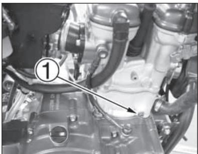
natural_image
Close-up of an automotive engine component with hoses and a numbered annotation (1), no readable text or symbols present.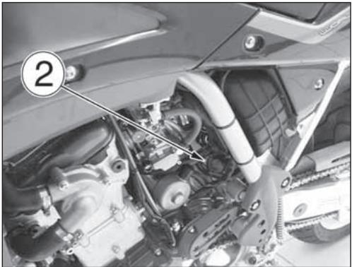
natural_image
Close-up of a car engine bay with visible components and a numbered annotation (2), no readable text or symbols present.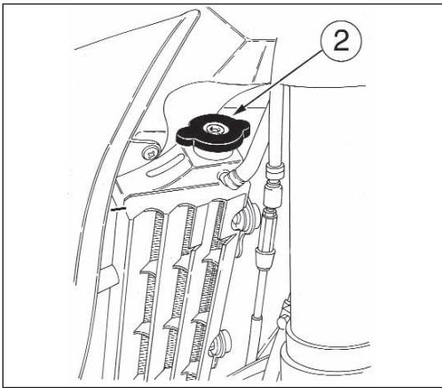
text_image
Technical diagram of a mechanical assembly with labeled component '2'Periodically check the connecting hoses (see “Periodical maintenance card”): this will avoid coolant leakages and consequent engine seizure: If hoses (A) show cracks, swelling or hardenings due to sheats desiccation, their replacement shall be advisable. Check the correct tightening of the clamps (B).
THROTTLE CABLE ADJUSTMENT To check the correct adjustment of the throttle operate as follows:
- remove the upper rubber cap (1);
- by moving cable (2) back and forth check for 2 mm. clearance;
- should the clearance be incorrect, unblock the counter ring-nut (3) and turn the adjusting screw (4) (by unscrewing it, the clearance is reduced, while by screwing screw (4) it is increased);
- tighten the counter ring-nut again (3).
WARNING*: Operation with damaged throttle cable could result in an unsafe riding condition.
text_image
Labeled diagram of a mechanical or electrical component with numbered parts 1, 2, 3, and 4 pointing to different cable types.NOTE (SMR 400 excluded)
In case of throttle control cables (1) and (2) replacement it is necessary to respect, during reassembly, the measure A (10mm/0.4 in.), as shown in the picture. Then reassemble guard cover (B) using screw (3) and adjust throttle control cables on handlebar as shown on page 106.
To replace throttle control cables, first remove tha fuel tank as shown on page 114.
NOTE (exclu SMR 400)
ADJUSTING THE CARBURETTOR (SMR 400 excluded)
Adjust the carburettor with warm engine and with the throttle in closed position.
Work as follows:
- Turn slow running adjusting screw (1) on the left side of the bike, , until the engine is turning over at fairly high rpm (turn the screw clockwise to increase the rpm, and anticlockwise to decrease the rpm).
- Turn adjusting screw (2) clockwise until the fully closed position is reached then turn back 1,5 turns (250-450) or 2 turns (510).
- progressively loosen adjusting screw (1) to obtain the slow running required.
ADJUSTING THE IDLE (SMR 400 excluded)
Adjust the carburetor with warm engine and with the throttle control in closed position. Proceed as follows:
- Turn slow running adjusting screw (1) on the left side of the bike, near the fuel cock (turn the screw clockwise to increase the rpm, and anticlockwise to decrease the rpm).
REGLAGE DU CARBURATEUR (exclu SMR 400)
text_image
Technical diagram of an engine component with numbered parts labeled 1 and 2REGISTRAZIONE CARBURATORE (SMR 400)
Adjust the carburettor with warm engine and with the throttle in closed position. Work as follows:
- Turn slow running adjusting screw (1) on the left side of the bike, , until the engine is turning over at fairly high rpm (turn the screw clockwise to increase the rpm, and anticlockwise to decrease the rpm).
- Turn adjusting screw (2) clockwise until the fully closed position is reached then turn back 2 turns.
- progressively loosen adjusting screw (1) to obtain the slow running required.
REGLAGE DU CARBURATEUR (SMR 400)
Adjust the carburetor with warm engine and with the throttle control in closed position. Proceed as follows:
- Turn slow running adjusting screw (1) on the left side of the bike, near the fuel cock (turn the screw clockwise to increase the rpm, and anticlockwise to decrease the rpm).
REGLAGE DU RALENTI SMR 400
natural_image
Close-up of a mechanical assembly showing internal components and tubing (no visible text or symbols)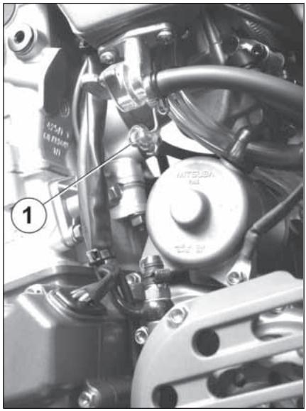
natural_image
Close-up mechanical assembly showing a motor and suspension components (no visible text or symbols)WARNING*: Exhaust gas contains poisonous carbon monoxide gas. Never run the engine in a closed area or in a confined area.
SPARK PLUG CHECK
Use NGK CR8EB spark plug; the gap is 0.027 in.
A wider gap may cause difficulties in starting engine and in overloading coil.
A gap that is too narrow may cause difficulties when accelerating, when idling the engine or when performing at low speeds.
Clean the dirt away from the base of the spark plug before removing it from the cylinder.
It is very useful to examine the state of the spark plug just after it has been removed from the engine since the deposits on the plug and the colour of the insulator provide useful indications.
Correct heat rating:
The tip of the insulator should be dry and the colour should be light brown or grey.
High heat rating:
In this case, the insulator tip is dry and covered with dark deposits.
Low heat rating:
In this case, the spark plug is overheated and insulator tip is vitreous, white or grey in colour.
natural_image
Close-up of an automotive engine bay with visible hoses and components, no text or symbols presentCAUTION*: Select a spark plug with a colder or hotter heat range carefully and cautiously. A spark plug with too hot a heat range may lead to preignition and possible engine damage. A spark plug with too cold a heat range may foul as the result of too much carbon buildup.
Before refitting the plug, thoroughly clean the electrodes and the insulator using a brass-metal brush. Apply a little graphite grease to the spark plug thread; fit and screw the spark plug by hand then tighten to the torque of 10÷12 Nm-7.4÷8.9 ft/lb. Loosen the spark plug then tighten it again to the torque of 10÷12 Nm-7.4÷8.9 ft/lb. Spark plugs which have cracked insulators or corroded electrodes should be replaced.
VOLTAGE REGULATOR (TE-SMR)
The voltage regulator (1) is fastened on the right side of the frame at the back of the steering sleeve.
Apply a little graphite grease to the spark plug thread; fit and screw the spark plug by hand then tighten to the torque of 10÷12 Nm-7.4÷8.9 ft/lb. Loosen the spark plug then tighten it again to the torque of 10÷12 Nm-7.4÷8.9 ft/lb.
natural_image
Close-up of a mechanical component with a numbered annotation (1) pointing to a feature, no readable text or symbols present.To check the valve clearance, proceed as follows, WITH COLD ENGINE:
First turn counterclockwise fastening rear pin (1) then remove the saddle; Set the fuel cock (2) on OFF position then loosen clamp (3) on the carburettor fuel hose; remove the hose from the fuel cock.
Remove the fuel tank fastening screw (A) then the fuel tank assembly with conveyors.
REGLAGE DU JEU DES SOUPAPES
natural_image
Close-up of a mechanical component with a labeled arrow pointing to a circular feature, marked with letter A (no text or symbols beyond label)Remove the spark plug (5), the four cylinder head cover fastening screws (6) and the cylinder head cover; Engage second gear and, moving the vehicle forwards and backwards, bring the piston to Top Dead Center (in this condition, the mark on the cylinder head is aligned with the two marks on the idle gear of the camshafts, as illustrated in the figure); Check, by means of a feeler gauge, that the valve clearance is 0,10÷0,15 mm (0.004÷0.006 in.) for INTAKE and 0,15÷0,20 mm (0.006÷0.008 in.) for EXHAUST; Otherwise, lift the retaining clip (7) using a hook, let the rocker arm slide to one side, extract the pad with a pair of pliers and check the thickness; Depending on the result, fit a new pad (as spare parts, pads are supplied ranging from 1.60 mm to 2.60 mm in steps of 0.05 mm) and return the clip and rocker arm; Check the valve clearance again and, if it's correct, reassembly the removed parts using the reverse procedure.
natural_image
Close-up of a mechanical engine assembly with numbered components (no visible text or symbols)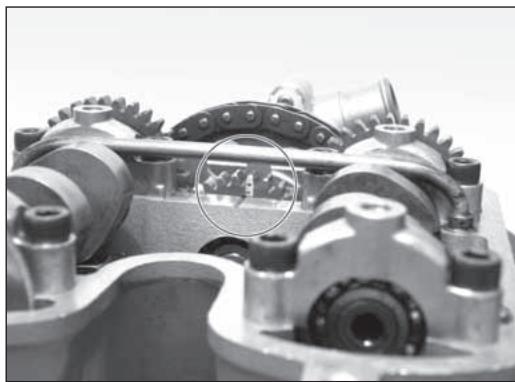
natural_image
Close-up of a mechanical gear assembly with no visible text or symbols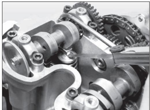
natural_image
Close-up of mechanical gears and linkages in a vehicle (no visible text or symbols)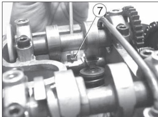
natural_image
Close-up of mechanical gear assembly with numbered component (7), no visible text or symbolsCONTROLLO FILTRO ARIA
Turn rear pin (1) counterclockwise, remove the saddle from the front afstening screw. Turn forward the housing box complete with the battery (1) (it is not necessary to remove the battery from its housing box). To gain access to the air filter, lift a little the electronic power unit (2). Remove screw (3) and the filter (4). Separate filter (5) from frame (6).
AIR FILTER AND CLEANING
Wash the filter with a specific detergent (AGIP" Filter clean foam air detergent fluid" or similar) then dry it fully (wash filter with gasoline only in case of necessity). Plunge the filter in special oil for filters (AGIP "Foam air filter protection oil" or similar), then wring it to drain superfluous oil.
CAUTION*: Do not use gasoline or a low flash-point solvent to clean the element. A fire or explosion could result.
CAUTION*: Clean the element in a well ventilated area, and do not allow sparks or flames anywhere near the working area.
ASSEMBLY
To ensure tight fit, slightly (C) grease filter edge on side facing filter housing. While re-inserting the filter into its housing make surs that piece A is turned upwards and edge B is on the left lower side of the filter case. Reassemble the parts previously removed (battery: connect the positive cable first).
CAUTION*: If the element assembly is not installed correctly, dirt and dust may enter and the engine resulting in rapid wear of the piston rings and cylinder.
CONTROLE FILTRE A AIR
natural_image
Illustration of a mechanical component with a circular feature and curved motion lines, no text or symbols present.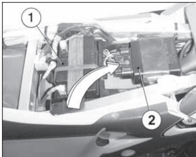
text_image
Technical diagram showing labeled components of a mechanical or electrical assembly with numbered annotations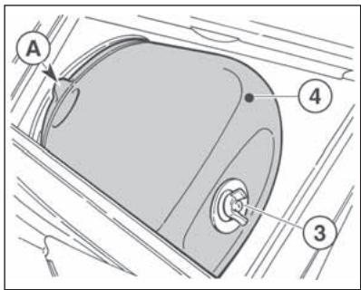
text_image
A 4 3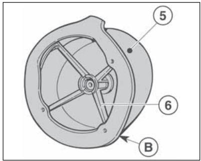
text_image
Technical diagram of a mechanical component with numbered parts labeled 5, 6, and B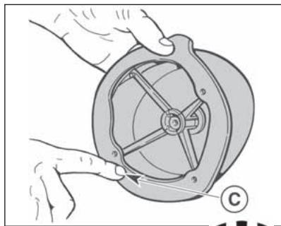
natural_image
Illustration of hands operating a mechanical component with a circular housing and a labeled section (no text or symbols)To ensure maximum safety, the steering wheel should always be regulated so that the handlebars steering the motorcycle rotate freely without play. To check steering wheel adjustment, place kick stand or other support under the engine so that the front wheel is raised from ground. Place slight pressure on the tips of the handlebars to rotate steering wheel; the handlebars should also rotate without effort. Stand in front of the motorcycle and grasp the lower end of the fork rods sliders moving them in the direction of their axis.
REGLAGE DU JEU DES PALIERS DU GUIDON
natural_image
Side view of a white and black MiR100 motorcycle with visible dynamics and suspension components (no text or symbols)If play is noticed, proceed with adjustment as follows:
- loosen steering sleeve nut (1);
- loosen four screws that fix steering head to fork rods (3);
- Turn the steering ring nut (2) clockwise of the steering sleeve proper tool, to adjust play properly;
- tighten steering sleeve nut (1) to a torque setting of 57,9÷65,1 Lb/ft; (78,4÷88,3 Nm)
- tighten four screws on the steering head (3) to a torque of 22,5÷26,5 Nm (16.6÷19.5 Lb/ft).
CAUTION*: Do not ride a motorcycle with damaged steering stem bearings. An unsafe handling condition can result.
text_image
Technical diagram of a mechanical assembly with numbered components labeled 1, 2, and 3.ADJUSTMENT OF THE CONTROL LEVER AND CHECK OF THE FRONT BRAKE FLUID LEVEL On the SMR model the lever position can be adjusted (4 adjustments) for any driver hand size. To decrease the lever distance from the handle grip, turn the adjuster (B) CLOCKWISE. To increase the lever distance from the handle grip, turn the adjuster (B) COUNTERCLOCKWISE. On the TE and TC models the adjuster (2), located on the control lever, allows adjusting of the free play (a). Free play (a) must be at least 3 mm (0.1 in.). The level of the fluid in pump reservoir must never be below the minimum value (1), which can be checked from the window on the rear side of the pump body (TE, TC). For SMR model, check the level on the fluid reservoir. A decrease of the fuel level will let air into the system, hence an extension of the level stroke.
WARNING*: If the brake lever feels mushy when it is applied, there may be air in the brake lines or the brake may be defective. Since it is dangerous to operate the motorcycle under such conditions, have the brake checked immediately by an authorized HUSQVARNA dealer.
text_image
Technical diagram of a mechanical assembly with numbered components and an inset view labeled B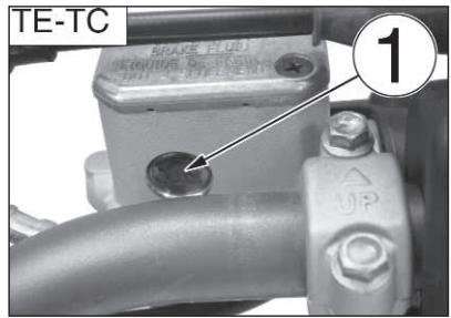
text_image
TE-TC SPAKE 2.002.00
1 UP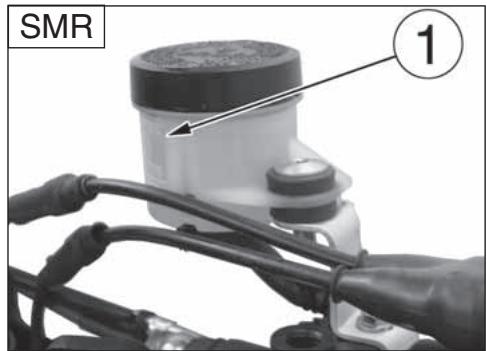
text_image
SMR ①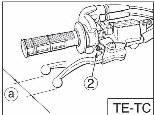
text_image
TE-TC a 2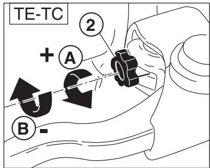
text_image
TE-TC + A 2 B -A: to encrease clearance
B: to decrease clearance
CAUTION*: Do not spill brake fluid on to any painted surface or lenses.
CAUTION*: Do not mix two brands of fluid. Change the brake fluid in the brake line if you wish to switch to another fluid brand.
CAUTION*: Brake fluid may cause irritation. Avoid contact with skin or eyes. In case of contact, flush thoroughly with water and call a doctor if your eyes were exposed.
REAR BRAKE PEDAL POSITION ADJUSTMENT
The position of the rear foot brake pedal as to the footrest may be adjusted according to the individual needs. For the adjusting proceed as follows:
- loosen the screw (1);
- turn the cam (2) in order to adjust the brake pedal idle stroke (A);- the operation done, tighten the screw (1).
The adjusting operation carried out, adjust the idle stroke of the pedal as indicated in page 128.
The rear brake foot pedal should have a (B) 5 mm (0.2 in.) idle stroke before starting the true braking action. Should this not happen as follows:
- loosen nut (3);
- operate the pump rod (4) to increase or decrease the idle stroke;
- tighten nut (3) at the end of the operation.
WARNING
When the idle stroke figures are not met, the brake pads will be subjected to a fast wear that may bring to the TOTAL BRAKE INEFFECTIVENESS.
CHECKING THE FLUID LEVEL The level (A) must be set between the pump tank notches of MIN and MAX.
text_image
Technical diagram of a vehicle's internal components with labeled parts and directional arrow B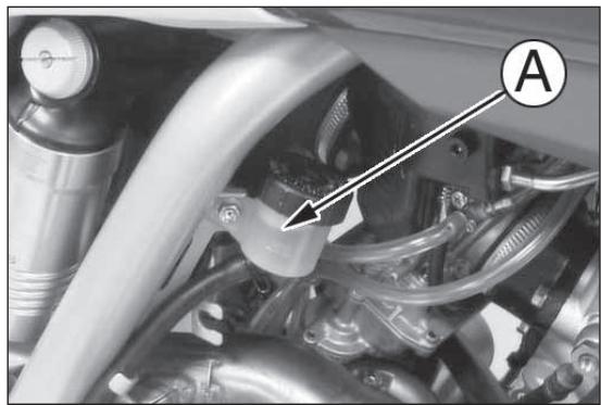
natural_image
Close-up of a mechanical assembly with hoses and components, no visible text or symbolsADJUSTMENT OF THE CONTROL LEVER AND CHECK OF THE HYDRAULIC CLUTCH FLUID LEVEL
Free play (A) must be at least 3 mm (0.1 in.).
The lever position can be adjusted for any driver hand size.
To decrease the lever distance from the handle grip, rotate the adjuster (B) CLOCKWISE.
To increase the lever distance from the handle grip, rotate the adjuster (B) COUNTERCLOCKWISE.
To check the fluid level, proceed as follows:
- remove screws (1), cover (2) and rubber pump diaphragm on the handlebar clutch control;
- by keeping the master cylinder (3) in horizontal position, check the fluid level is NOT BELOW 4 mm (0.16 in.) from the upper surface (D) of the pump body;
- if necessary, add fluid until the correct level is reached (see
TABLE FOR LUBRICATION-SUPPLIES for the fluid type page 44)
CAUTION *: NEVER use brake fluid.
Reassembly the removed parts using the reverse procedure.
Periodically check the connecting hose (see “Periodical maintenance card”): if the hose (C) show is bent or cracked, its replacement is advised,
REGLAGE DU LEVIER DE COMMANDE ET CONTRÔLE DU NIVEAU FLUIDE DE L'EMBRAYAGE HYDRAULIQUE
text_image
TC 1 2 B A 3 C D 4 mm (0.16 in.)HYDRAULIC CLUTCH BLEEDING
Proceed as follows:
- remove screws (1), cap (2) and rubber pump diaphragm;
- remove the bleeding nipple (3);
- mount a syringe in the bleeding nipple hole, then refill with fresh fluid (see LUBRICATION TABLE on page 44).
CAUTION *: NEVER use brake fluid.
Refill until fluid is discharged from the lower hole (B) on the pump body WITHOUT BUBBLES. The fluid level MUST NEVER BE below 4 mm from the top (A) of the clutch pump body (see picture). Reassemble the removed parts.
PURGE DE L'EMBRAYAGE HYDRAULIQUE
Agir comme suit:
natural_image
Close-up mechanical assembly showing engine components and a numbered label (3), no readable text or symbols present.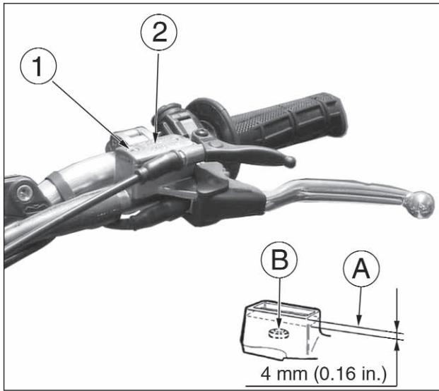
text_image
① ② B A 4 mm (0.16 in.)ADJUSTING THE SUSPENSIONS ACCORDING TO PARTICULAR TRACK CONDITIONS
The following information is a useful guide for setting up the suspensions according to the road conditions.
Always start from the standard calibration before making any change on the suspensions. Afterwards, increase or decrease the adjusting clicks one at a time.
HARD GROUND
Fork: softer compression adjustment.
Shock absorber: softer compression adjustment.
The softer adjustment for the two suspensions is also used both in compression and in extension when driving at top speed, in order to have better grip of the tires.
SANDY GROUND
Fork: have a harder compression adjustment, or replace the standard spring with a harder one, and make a softer compression adjustment and a harder extension adjustment at the same time.
Shock absorber: have a harder compression, and especially a harder extension adjustment. Work on the spring preload to lower the motorcycle rear side.
REGLAGE DES SUSPENSION PAR RAPPORT AUX CONDITIONS DE LA PISTE
Fork: have a harder compression adjustment, or replace the standard spring with a harder one.
Shock absorber: have a harder compression and extension adjustments, or replace the standard spring with a harder one. Work on the spring preload to lift the motorcycle rear side. We advise replacing the springs of both suspensions to compensate the weight increase due to the piling of the mud.
TERREIN BOUEUX
When the fork results as either too soft or too hard for any adjustment conditions, check the oil level inside the forkrod.
The level can either be too low or too high. Remember that too much oil inside the fork will involve a more frequent air drainage. When the suspensions do not react to the changes of calibration, check that the adjusting units are not blocked.
The standard calibrations and the adjustment procedures are shown on the next pages. The springs available upon request, together with the preload spacers, are shown on pages
NOTE:
natural_image
Black-and-white action photo of a motorcyclist mid-jump, wearing helmet and number 52, with no visible text or symbols on the bike or background.
natural_image
Black-and-white photo of a motorcyclist in action on a dirt track, kicking up dust (no visible text or symbols)
natural_image
Black-and-white action photo of a dirter mid-jump, kicking up dust (no visible text or symbols)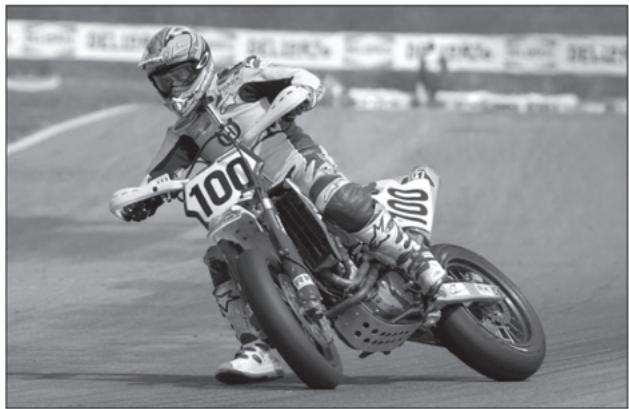
natural_image
Black-and-white photo of a motorcyclist performing a trick on a track, wearing racing gear and number 100 (no visible text or symbols)Standard calibration: -20 clicks (TC);
Standard calibration: -12 clicks (TE-SMR).
Remove plug (B) and turn register (A) clockwise until the position of fully closed is reached then, turn back by the mentioned clicks. To obtain a smoother braking action, turn the register anticlockwise.
Reverse the operation in order to obtain a harder action.
b) EXTENSION (UPPER REGISTER)
Standard calibration: - 10 clicks (TE 250);
Standard calibration: - 12 clicks (TE-SMR 450, 510; TC).
To reset standard calibration turn register (C) clockwise to reach the position of fully closed; then, turn back by the mentioned clicks. To obtain a smoother braking action, turn the register anticlockwise.
Reverse the operation in order to obtain a harder action.
c) AIR VENT (to carry out after each competition, or monthly). Set the motorcycle on a central stand and release the fork fully and loosen the air vent valve (D). Once this operation is over, tighten the valve.
REGLAGE FOURCHE A COMPRESSION
a) COMPRESSION (REGISTRE INFÉRIEUR)
natural_image
Close-up of a mechanical component with a rotary knob and cross symbol (no readable text or symbols)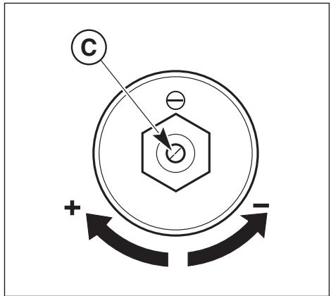
chemical
Diagram of electron spin states in a positively charged particle system with labeled positive and negative charges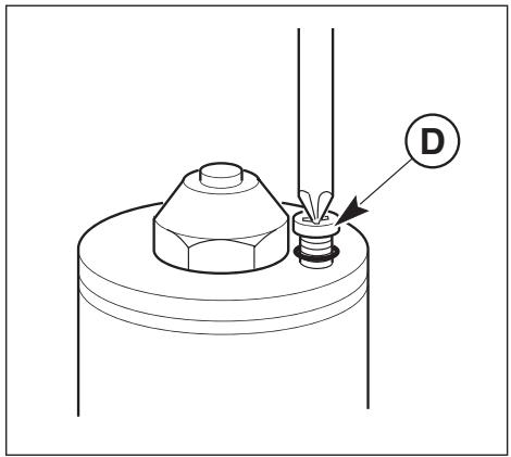
text_image
Technical diagram showing a mechanical assembly with labeled component D and directional arrowWARNING: Never force the adjusting screws beyond the maximum opening and closure positions.
For the regular fork operation, both legs must be provided with the necessary oil quantity.
Remove the forkrods form the fork to check the oil level inside the forkrods. Work as follows:
- remove the power rod caps;
- remove springs from the stems letting the oil drop into the latter;
- bring forks to stroke end;
- check that the level is at distance "A" below the upper limit of rods.
NOTE
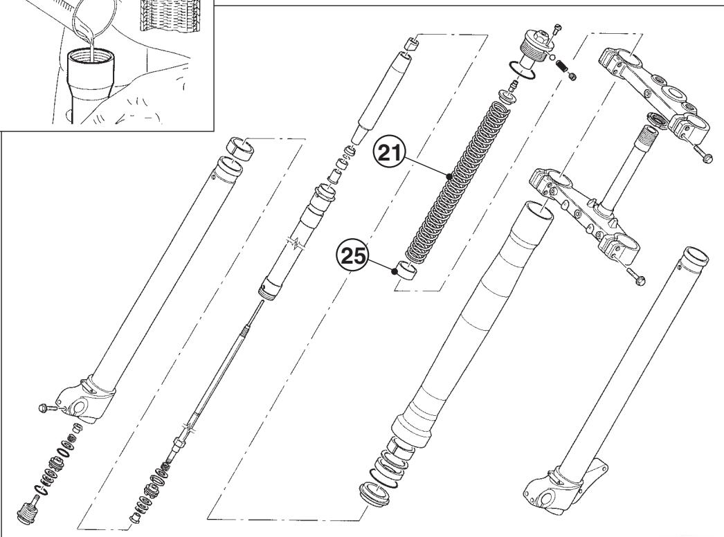
Besides the serial spring (21) with flexibility index K=4.8 N/mm (TE-TC) and K=5 (SMR) and relevant preload (25) spacer harder or softer springs, together with spacers are aballable upon request.
NOTE
Always replace both the spring and the spacers to keep the preload value unchanged.
NIVEAU D'HUILE DE LA FOURCHE
text_image
Diagram illustrating a hand pouring liquid into a container with an inset showing a bottle and water displacement measurement.A=90mm (3.54 in.)- TE 250, TC 450-510
A=100mm (3.94 in.)- TC 250
A=110mm (4.33 in.)- SMR
A=120mm (4.72 in.)- TE 450-510
text_image
Technical diagram of mechanical assembly with numbered parts, including a zoomed-in view of a component.MODIFICA POSIZIONE ED ALTEZZA MANUBRIO
The handlebar position (a) and height (b) can be changed for better suiting Your driving requirements. To effect these operations, remove the upper screw (3), upper clamp (1), lower screw (4) then lower clamp (2).
a) Handlebar position change Turn the lower clamp (2) 180° to move forward or backward (10mm- 0.04in.) the handlebar position with respect to the original setup. b) Handlebar height change Remove the lower spacer (A) then replace the screw (4) with a new one of L=65 mm (2.56 in.) height.
Once these operations are completed, tighten the screws (3) to 2,75-3,05 kgm (27-30 Nm; 19.9-22 Lb/fts) and the screws (4) to 2,0-2,2 kgm (19,6-21,6 Nm; 14.5-15.9 Lb/fts).
MODIFICATION DE LA POSITION ET DE L'HAUTEUR DU GUIDON
text_image
Labeled mechanical component diagram showing parts numbered 1 to 4 with arrows indicating assembly or movement.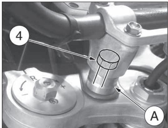
text_image
A 4 R X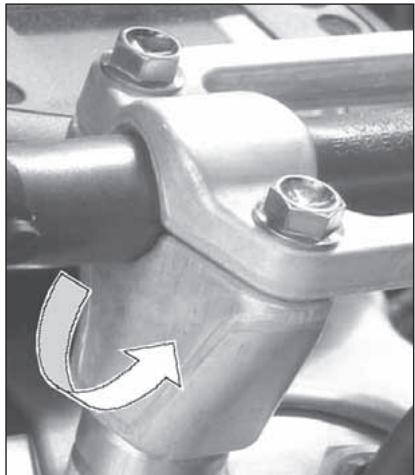
natural_image
Close-up of a mechanical coupling with bolts and a curved arrow indicating rotational motion (no text or symbols)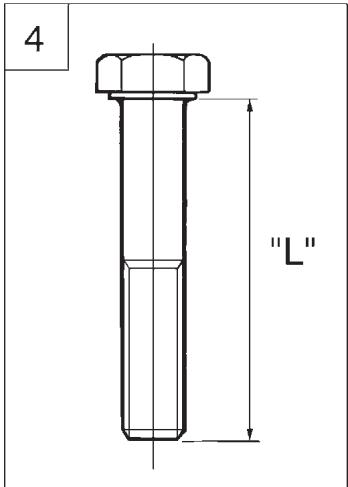
text_image
4 "L"REGISTRAZIONE AMMORTIZZATORE
The rear shock absorber must be adjusted according to the rider weight and track conditions.
Proceed as follows:
- With motorcycle on the stand, measure distance (A).
- Take the normal riding position on the motorcycle with all your riding apparel.
- With somebody's help, take the new distance (A).
- The difference between these two measurements constitutes the "SAG" of the motorcycle's rear end.
Suggested SAG: 4 in. with cold shock absorber. 3.7 in. with warmed up shock absorber.
- To get the right SAG according to your weight, adjust the shock absorber spring preload (page 146).
WARNING*: Never disassemble shock absorber, which contains highly compressed nitrogen. Contact your Dealer for such major service. Do not incinerate.
ADJUSTING THE SHOCK ABSORBER SPRING PRELOAD Proceed as follows:
- First turn counterclockwise fastening rear pin (1) then remove saddle, screws (2) and R.H. side panel (3).
- Clean ringnut (1) and adjusting nut (2) of the spring (3).
- Either with a hook wrench or an aluminium punch, loosen the ringnut.
- Turn the adjusting nut as required.
- When the adjusting operation is over (according to your weight and riding style), tighten the ringnut. (Torque for both ringnuts: 5 Kgm; 49 Nm; 36.2 ft/lb).
- Reassemble R.H. side panel and saddle.
WARNING*:Be careful not to touch hot exhaust pipe while adjusting the shock abosrber.
natural_image
Diagram of a car handle with a circular component and curved motion lines, no text or symbols present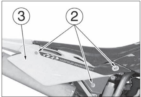
text_image
③ ② HOTOM SPORTS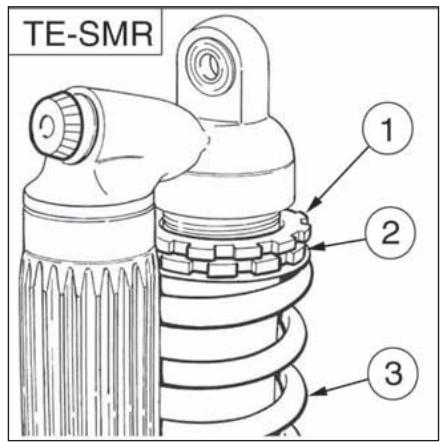
text_image
TE-SMR ① ② ③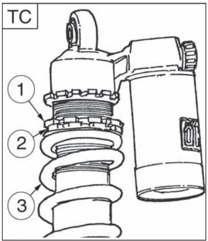
text_image
TC ① ② ③REGISTRAZIONE FRENO IDRAULICO AMMORTIZZATORE
(BEFORE the following operation, please see the IMPORTANT NOTICE 2) on page 12
Adjustment of the compression stroke is independent from the rebound stroke.
A) COMPRESSION - Standard calibration:
1) Low damping speed:
● TE-TC: -15 clicks (± 2 clicks)
● SMR: -5 clicks (± 2 clicks) (register 4)
2) High damping speed:
● TC 250-450-510: -15 clicks (± 2 clicks)
● TE 250-450-510: -12 clicks (± 2 clicks)
● SMR 400-450-510: -15 clicks (±2 clicks)
(register 6)
To reset the standard calibration, turn upper registers (4) and (6) clockwise until reaching fully closed position. Return then back for the mentioned clicks. In order to obtain a smooth braking action, turn the registers anticlockwise. Reverse the operation in order to obtain a harder braking action. B) EXTENSION - Standard calibration:
● TC 250-450-510: -25 clicks (±2 clicks)
● TE 250-450-510: -16 clicks (± 2 clicks)
● SMR 400-450-510: -16 clicks (±2 clicks)
To reset the standard calibration, turn lower register (5) clockwise until reaching fully closed position. Return then back for the mentioned clicks. In order to obtain a smooth braking action, turn the register anticlockwise. Reverse the operation in order to obtain a harder braking action.
● TE-TC: -15 clicks (± 2 clicks)
● SMR: -5 clicks (± 2 clicks) (registre 4)
● TC 250-450-510: -15 clicks (± 2 clicks)
● TE 250-450-510: -12 clicks (± 2 clicks)
● SMR 400-450-510: -15 clicks (±2 clicks)
(registre 6)
● TE 250-450-510: -16 clicks (± 2 clicks)
● TE-TC: -15 Klicks (± 2 Klicks)
● SMR: -5 clicks (± 2 clicks) (Eintellschraube 4)
● TC 250-450-510: -15 Klicks (± 2 Klicks)
● TE 250-450-510: -12 Klicks (± 2 Klicks)
● SMR 400-450-510: -15 clicks (±2 clicks) (Eintellschraube 6)
Chain should be checked, adjusted and lubricated as per the Maintenance Chart to ensure security and prevent excessive wear. If the chains becomes badly worn or is poorly adjusted (i.e., if it is too loose or too taught), it could escape from sprocket or break. To adjust the rear chain it is necessary to lower the rear part of motorcycle so to line up the drive sprocket axle, the rear swing arm axle and the rear wheel axle as shown on drawing. Than let turn three times the rear wheel. Now the chain should not be tight. (Fig. A).
Fast adjustment (Fig. B.). Push the chain towards the final part of runner and check that between the two elements a distance "A" from 0 to 2 mm (0.08 in.) is present. If this is not the case, go on as follows:
- unloose the fastening nut (1) of the wheel axle on the R.H. side;
- Unloose the lock nuts (2) on both chain adjusters and turn the screws (3) to obtain the correct tension value;
- Tighten the lock nuts. After adjustment check that the wheel is lined up and tighten its axle.
A = 0÷2 mm (0÷0.08 in.)
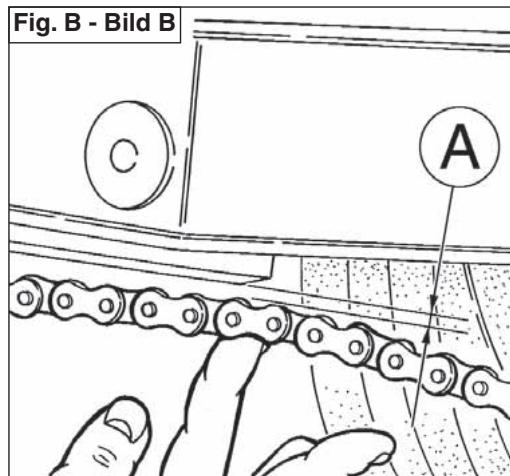
CHECKING THE WEAR OF CHAIN, PINION AND SPROCKET
Proceed as follows:
- Fully stretch the chain with the adjusting screws.
- Mark 20 chain links.
- measure the distance "A" between 1st pin center and 21 st pin center.
| STANDARD | WEAR LIMIT |
| 317,5 mm(12.5 in.) | 323 mm(12.7 in.) |
Check the pinion damages or wear and replace it should the wear degree be as the one shown in figure.
Remove the wheel and check the wear of the rear sproket teeth. The figure shows the outline of teeth in normal and excessive wear. Should the sprocket be badly worn out, replace it by loosening the six fastening screws to the hub.
WARNING*: Misalignment of the wheel will result in abnormal wear and may result in an unsafe riding condition.
Note*: In muddy and wet conditions, mud sticks to the chain and sprockets resulting in an overtight chain. The pinion, the chain, and the rear sprocket wheel wear increases when running on muddy ground.
CONTROLE USURE CHAINE, PIGNON ET COURONNE
Agir comme suit:
natural_image
Black and white geometric gear-like shape with radial teeth and central hole (no text or symbols)
flowchart
graph TD
    A["Consumo normal"] --> B["Normal consumption"]
    B --> C["Consommation normale"]
    C --> D["Normaler verbrauch"]
    D --> E["Consumo normal"]
    F["Consumo excessive"] --> G["Excessive consumption"]
    G --> H["Consommation excessive"]
    H --> I["Oververbrauch"]
    I --> J["Consumo excessive"]
LUBRICATING THE CHAIN
Lubricate the chain following these instructions:
WARNING * : Never use grease to lubricate the chain. Grease helps to accumulate dust and mud, which act as abrasive and hepl to rapidly wear out the chain, the sprocket, and the crown.
LUBRIFICATION CHAINE
Disassembling and cleaning
When particularly dirty, remove and clean the chain before lubrication.
Work as follows:
Set a stand or a block under the engine and see that the rear wheel is lifted from the ground.
Remove: screws (1), transmission sprocket guard (2), clip (3), master link (4) and transmission chain (5); To reassemble, reverse the above procedure.
text_image
Labeled diagram of a motorcycle's wheel assembly with numbered parts for identification2 - Check that the chain is neither worn out nor damaged. If the rollers or the links are damaged, replace the chain by following the instructions given in the Periodical Maintenance Table.
3 -Check that neither the sprocket nor the crown are damaged.
4 -Wash and clean the chain as described hereunder.
Washing the chain without OR
Wash using either oil or diesel oil. When using gasoline or tricloroetilene, clean and lubricate the chain to prevent oxidation.
Washing the chain with OR
Wash using oil, diesel oil, or paraffin oil. Never use gasoline, tricloroetilene, or solvents, as the OR may suffer damages.
Use instead special sprays for chains with OR.
Lubricating the chain without OR
First dry, then plunge the chain in a bisulphide molybdenum lubricant, or in high viscosity engine oil. Warm up the oil before use.
Lubricating the chain with OR
Lubricate all metallic and rubber (OR) elements using a brush, and use engine oil with SAE 80-90 viscosity for the internal and external parts.
5 - If the chain has been cut, reassemble using a joint.
6 - Assemble the joint spring by turning the closed side to the chain direction of rotation as shown in figure (page 155).
NOTE *: Even if all the joints are reusable when in good conditions, for safety purposes we advise using new joints when reassembling the chain. 6 -Accurately adjust the chain as described on page 150. WARNING: The chain oil has NEVER to get in contact with the tires or the rear brake disk.
Chain tension rollers, chain driving roller, chain guide, chain runner
Check the wear of the above mentioned elements and replace them when necessary.
WARNING * : Check the chain guide alignment, and remember that a bent element can cause a rapid wear of the chain. In this case, a chain fleeting from the sprocket may ensue.
text_image
Labeled diagram of a motorcycle's front wheel and drivetrain components with numbered parts1- Rullo tendicatena
2- Rullo guidacatena
3- Guidacatena
4- Pattino catena
1- Chain tension roller
2- Chain driving roller
3- Chain guide
4- Chain slider
Removing the front wheel
Set a stand or a block under the engine and see that the front wheel is lifted from the ground. Loosen the bolts (1) holding the wheel axle (2) to the front fork stanchions.
SMR: remove the two screws (A) and the brake caliper. Hold the head of the wheel axle (2) in place, unscrew the bolt (3) on the opposite side; draw the wheel axle out.
Do not operate the front brake lever when the wheel has been removed; this causes the caliper piston to move outwards. After removal, lay down the wheel with brake disc on top.
AVIS
natural_image
Side view of a white and silver MiR500 motorcycle on a stand, showing front wheel, rear wheel, and suspension components (no text or symbols visible)
text_image
SMR A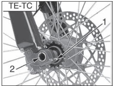
text_image
TE-TC 1 2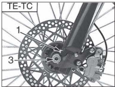
text_image
TE-TC 1 3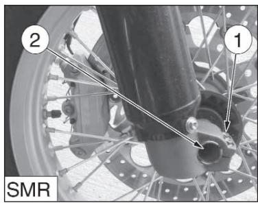
text_image
2 1 SMR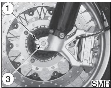
natural_image
Close-up of a mechanical brake assembly with labeled parts (1, 3), no readable text or symbols beyond labelsNOTAS
Reassembling the front wheel
Fit the L.H. spacer on the wheel hub.
TE-TC: Fit the wheel between the front fork legs so that the brake disc is fitted into the caliper.
SMR: Fit the wheel between the front fork legs.
Fit the wheel axle (2) from the R.H. side, after greasing it and push it to the stop on the L.H. leg; during this operation, the wheel should be turned. Tighten the screw (3) on the fork L.H. side but DO NOT lock it. Now, pump for a while, pushing the handlebar downwards until you are sure that the fork legs are perfectly aligned.
Lock: the screws (1) on the R.H. leg (10,4 Nm/ 1,05 Kgm/ 7.7 ft-lb), the screw (3) on the L.H. side (51,45 Nm/ 5,25 Kgm/ 38 ft-lb), the screws (1) on the L.H. leg (10,4 Nm/ 1,05 Kgm/ 7.7 ft-lb).
SMR: fit the brake caliper on the disc; assemble the caliper on its holding plate and tighten the screws (A) at 25,5 Nm/ 2,6 Kgm/ 18.8 ft-lb.
Check that the brake disc slides between the caliper pads without any friction.
NOTE
After reassembly, pump the brake control lever until the pads are against the brake disc.
natural_image
Mechanical assembly diagram showing a brake disc and wheel assembly with labeled parts (no readable text or symbols)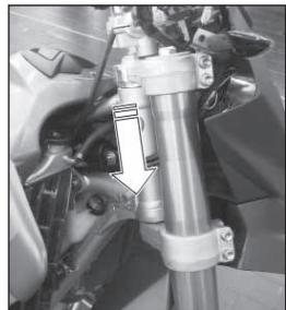
natural_image
Close-up of a mechanical assembly with no visible text or symbolsRemoving the rear wheel
Unscrew the nut (1) of the wheel pin (3) and extract it. It is not necessary to unloose the chain adjusters (2); in this way, the chain tension will remain unchanged after the reassembly. Extract the complete rear wheel, by taking care of the spacers located at the hub sides.
To reassemble, reverse the above procedure remembering to insert the disc into the caliper.
Do not operate the rear brake pedal when the wheel has been removed; this causes the caliper piston to move outwards.
After removal, lay down the wheel with brake disc on top. After reassembly, pump the brake control pedal until the pads are against the brake disc.
AVIS
text_image
Mechanical assembly diagram showing two labeled components (1 and 2) of a brake system with mechanical components and wiring.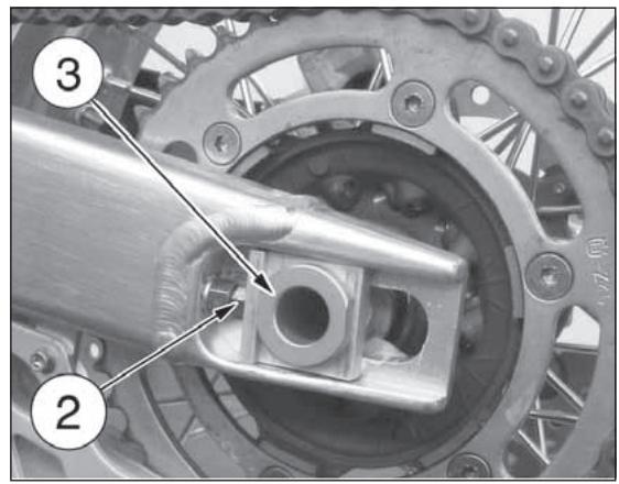
text_image
Mechanical assembly diagram showing a gear and component with numbered parts labeled 2 and 3PNEUMATICI
Care should be taken to keep the tires properly inflated. See tire data for correct tire inflation pressure (38). Replace the tire if its wear exceeds what is shown on the table below.
PNEUS
| FRONT | 0.12 in. (TC,TE); 0.08 in.(SMR) |
| REAR | 0.12 in. (TC,TE); 0.08 in.(SMR) |
| AVANT | 3 mm (TC,TE); 2 mm (SMR) |
| ARRIERE | 3 mm (TC,TE); 2 mm (SMR) |
REIFEN
natural_image
Close-up of a bicycle wheel with visible tire, disc, and hub assembly (no text or symbols)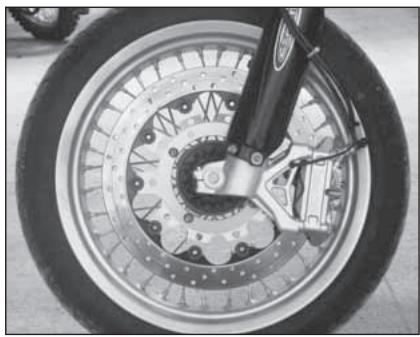
natural_image
Close-up of a motorcycle wheel and brake disc assembly (no text or symbols visible)FRENI
The mayor components are brake master cylinder with its lever (front) or pedal (rear), brakeline, caliper assembly and disc.
FREIN
- Front brake control lever
- Front brake pump with oil reservoir (TE, TC)
- Front brake pump (SMR)
2A. Oil reservoir (SMR) - Front brake hose
- Front brake caliper
- Front brake disc
- Rear brake oil tank
- Rear brake hose
- Rear brake caliper
- Rear brake disc
- Rear brake pump
- Rear brake control pedal
LEGENDE
Don't operate the brake lever or pedal while removing the pads.
ATTENTION!
USURA PASTIGLIE (TE)
Inspect pads for wear. Service limit "A" is: 3,8 mm (0.15 in.). If service limit is exceeded, always replace the pads in pairs.
USURE DES PASTILLES (TE)
USURA PASTIGLIE (SMR)
a) In front: thickness "A" must never be lower than the one pointed out by the wear control notches. b) At the back: thickness "A" must never be lower than 3,8 mm. If service limit is exceeded, always replace the pads in pairs.
USURE DES PASTILLES (SMR)
natural_image
Mechanical assembly diagram showing two labeled components (1 and 2) with no visible text or symbols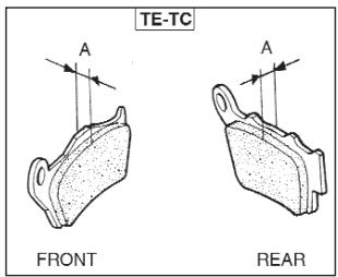
text_image
TE-TC FRONT REAR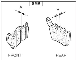
text_image
SMR FRONT REARPULIZIA PASTIGLIE
Be careful that no disc brake fluid or any oil gets on brake pads or discs. Clean off any fluid or oil that inadvertently gets on the pads or disc with alcohol. Replace the pads with new ones if they cannot be cleaned satisfactorily.
NETTOYAGE DES PASTILLES
- Install new brake pads.
- Reassemble the two pins (2) and the springs (1).
MONTAGE DES PASTILLES
Do not attempt to ride the motorcycle until the brake lever or pedal are fully effective. Pump the brake lever or pedal until the pads are against the discs. The brake will not function on the first application of the lever or pedal.
ATTENTION!
natural_image
Mechanical assembly diagram showing two labeled components (1 and 2) with no visible text or symbolsUSURA DISCO FRENO
Measure the thickness of each disc at the point where it has worn the most. Replace the disc if it has worn past the service limit.
Disc Thickness
Measure disc warpage. Service limit for both discs is 0,15 mm (0.006 in.) Replace the disc if warpage is more than service limit.
DISQUE PAPILLOTANT
natural_image
Technical line drawing of a bicycle wheel assembly with visible gears and levers (no text or symbols)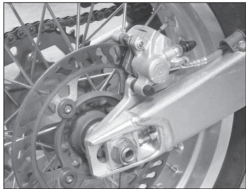
natural_image
Close-up of a bicycle's front wheel and brake system (no visible text or symbols)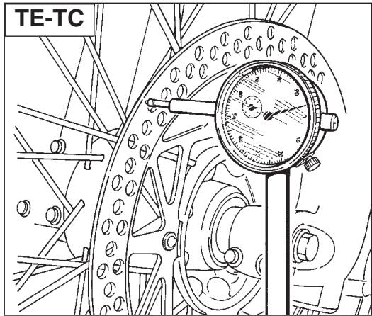
natural_image
Technical line drawing of a mechanical gauge or dial assembly (no text or symbols)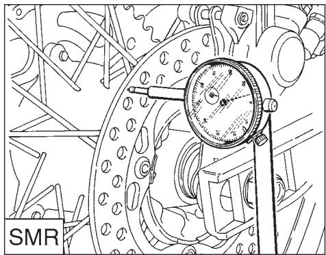
natural_image
Technical line drawing of a mechanical assembly with a dial indicator (no text or symbols)PULIZIA DISCO
Poor braking can also be caused by oil on the disc. Oil or grease on the disc must be cleaned off with a high flash-point oil free solvent, such as acetone or lacquer thinner.
NETTOYAGE DU DISQUE
natural_image
Technical line drawing of a bicycle wheel assembly with visible gears and levers (no text or symbols)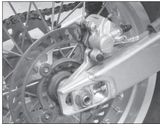
natural_image
Close-up of a bicycle's wheel and suspension system components (no visible text or symbols)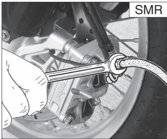
natural_image
Close-up of a hand using a wrench to connect a car tire with a cable, no visible text or symbolsSOSTITUZIONE FLUIDO
The brake fluid should be checked and changed in accordance with the Periodic Maintenance Chart or whenever it is contaminated with dirt or water. Don't change the fluid in the rain or when a strong wind is blowing.
CAUTION!
* Use only brake fluid from a sealed container (DOT 4). Never use old brake fluid.
* Never allow contaminants (dirt, water, etc.) to enter the brake fluid reservoir.
* Don't leave the reservoir cap off any length of time to avoid moisture contamination of the fluid.
* Handle brake fluid with care because it can damage paint.
* Don't mix two types of fluid for use in the brake. This lowers the brake fluid boiling point and could cause the brake to be ineffective. It may also cause the rubber brake part to deteriorate.
REPLACEMENT DU FLUIDE
To replace the fluid, proceed as follows:
- Remove the rubber cap on the bleeding valve (1) or (1A).
- Attach a clear plastic hose to the bleeding valve on the brake caliper and turn the other end of the hose into a container.
- Remove fluid reservoir cap (2) or (2A) and the rubber.
- Loosen bleeding valve on the brake caliper.
natural_image
Mechanical assembly diagram showing a motor and linkage mechanism (no text or labels)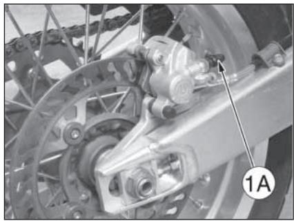
natural_image
Mechanical assembly diagram showing a brake system with labeled component (1A), no readable text or symbols present.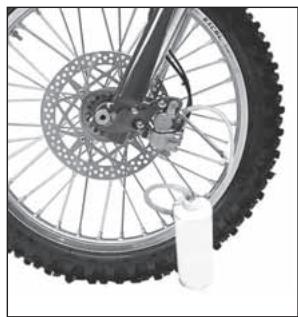
natural_image
Close-up of a bicycle wheel with visible tire, disc, and bucket (no text or symbols)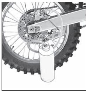
natural_image
Mechanical assembly diagram showing a wheel with gear and a cylinder inserted (no text or symbols)natural_image
Close-up of a mechanical lever handle and grip assembly (no visible text or symbols)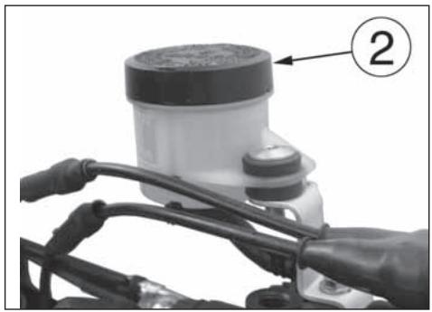
natural_image
Close-up of a motorcycle's front bumper with labeled component (2), no visible text or symbols on the body itself.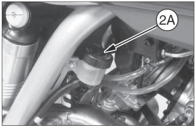
natural_image
Close-up of a mechanical assembly with hoses and components, no visible text or symbols- Pump with brake lever (3) or brake pedal (3A) in order to push brake fluid out of line.
- Close the bleeding valve and fill the reservoir with fresh brake fluid.
- Open the bleeding valve, apply the brake using the brake lever or pedal, close the bleeding valve with the brake lever or pedal applied and then quickly release the lever or pedal.
- Repeat this operation until the brake line is filled and clear fluid starts coming out of the plastic hose: now close the bleeding valve.- Restore the brake fluid level (A) or (B) then reassemble the rubber and the fluid reservoir cap (pag. 179).
After the brake fluid replacement, it is necessary to operate the braking system bleeding (see pages 184 and 192).
natural_image
Close-up of a mechanical lever handle and grip with a numbered annotation (3) pointing to the lever (no text or symbols on the object itself)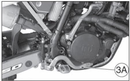
natural_image
Mechanical assembly diagram showing motor components and wiring (no text or symbols visible)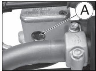
natural_image
Close-up of a mechanical pipe fitting with a labeled component (A), no visible text or symbols beyond the label.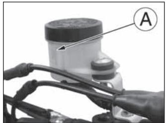
natural_image
Close-up of a motorcycle engine component with labeled parts (A), no visible text or symbols beyond the label.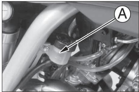
natural_image
Close-up of a mechanical assembly with hoses and components, no visible text or symbolsATTENZIONE!
Brake fluid quickly ruins painted surfaces; any spilled fluid should be completely wiped up immediately.
* Brake fluid may cause irritation. Avoid contact with skin or eyes. In case of contact, flush thoroughly and call a doctor if your eyes were exposed.
Periodically check the connecting hoses (see "Periodical maintenance card"): if the hoses (A) and (B) are worried or cracked, their replacement is advised.
ATTENTION!
natural_image
Close-up of a motorcycle's front wheel and steering wheel assembly, showing tire alignment and mounting bracket (no text or symbols)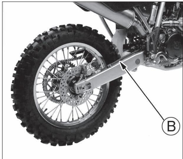
natural_image
Close-up of a motorcycle's front wheel and suspension components, labeled with number B (no text or symbols on the main subject)SPURGO IMPIANTO FRENANTE ANTERIORE (TE, TC)
The braking system must be bled after the fluid replacement or when, due to air in the circuit, the lever stroke is long and spongy. Proceed as follows:
- Remove the rubber cap on the bleeding valve (1).
- Attach a clear plastic hose to the bleeding valve on the brake caliper and turn the other end of the hose into a container (make sure that the end of the hose is submerged in brake fluid during the entire bleeding operation).
- Remove fluid reservoir cap (2), the rubber and fill the reservoir with fresh brake fluid.
- Open the bleeding valve and pump with brake lever (3) several times until the fluid, clear and without bubbles, comes out of the hose: now close the bleeding valve.
CURAGE INSTALLATION DE FREINAGE AVANT (TE, TC)
natural_image
Mechanical assembly diagram showing a brake caliper and suspension components (no text or labels)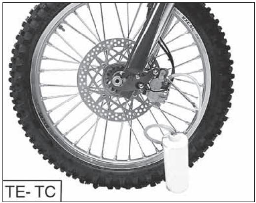
natural_image
Close-up of a bicycle wheel with visible tire, disc, and mechanical components (no text or symbols)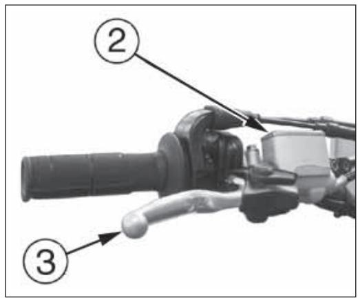
text_image
Diagram of a mechanical device with numbered parts labeled ②, ③, and ②- Restore the brake fluid level (A) then reassemble the rubber and the fluid reservoir cap (2).
WARNING!
During the bleed operation the fluid level inside the reservoir must never be lower than the minimum level.
Tightening torque for bleed valve is 1,2 ÷ 1,6 kgm ( 12 ÷ 16 Nm; 8.8 ÷ 11.8 ft-lb).

As the braking fluid is a very corrosive substance, in the case it comes in contact with your eyes wash them abundantly with water.

During the bleeding of the braking circuit keep the handlebar turned leftwards. This is the way to lift the pump tank and to make easier the ring of the braking system.

If the lever stroke gets stretchy and the braking action results as poor in the case of falls during competitions, or after repair work in shops, repeat bedding operation described above.

As the bleeding operation does not fully eliminate the air inside the circuit, the small quantity of air remaining inside will be eliminated short time of use of the brake. In this however, the action of the lever will be and the stroke shorter.
The braking system must be bled after the fluid replacement or when, due to air in the circuit, the lever stroke is long and spongy.
Regarding the front braking system, first proceed to bleed the upper braking system control (bleeding valve 1), then the brake caliper (bleeding valve 1A).
In both cases, proceed as follows:
- Remove the rubber cap on the bleeding valve (1) or (1A).
- Attach a clear plastic hose to the bleeding valve on the brake caliper and turn the other end of the hose into a container (make sure that the end of the hose is submerged in brake fluid during the entire bleeding operation).
- Remove fluid reservoir cap (2), the rubber and fill the reservoir with fresh brake fluid.
CURAGE INSTALLATION DE FREINAGE AVANT (SMR)
natural_image
Close-up of mechanical components with wires and connectors (no visible text or symbols)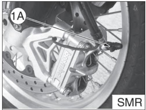
text_image
1A SMR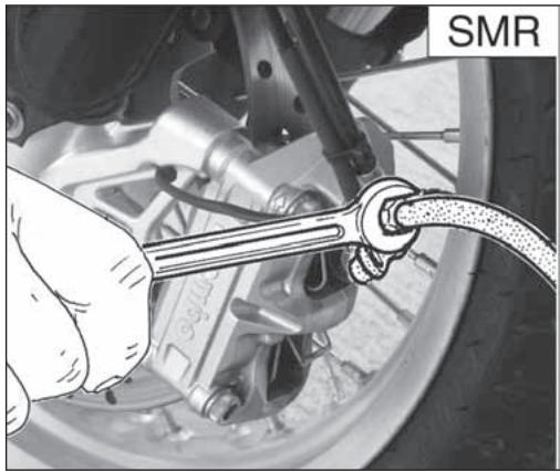
natural_image
Close-up of a hand using a wrench to connect a cable to a car wheel (no visible text or symbols)- Open the bleeding valve and pump with brake lever several times until the fluid, clear and without bubbles, comes out of the hose: now close the bleeding valve. - Restore the brake fluid level (A) then reassemble the rubber and the fluid reservoir cap.
During the bleed operation the fluid level inside the reservoir must never be lower than the minimum level. Tightening torque for bleed valve is 1,2 ÷ 1,6 kgm ( 12 ÷ 16 Nm; 8.8 ÷ 11.8 ft-lb).
ATTENTION!
During the bleed operation the fluid level inside the reservoir must never be lower than the minimum level.
Tightening torque for bleed valve is 1,2 ÷ 1,6 kgm ( 12 ÷ 16 Nm; 8.8 ÷ 11.8 ft-lb).

As the braking fluid is a very corrosive substance, in the case it comes in contact with your eyes wash them abundantly with water.

During the bleeding of the braking circuit keep the handlebar turned leftwards. This is the way to lift the pump tank and to make easier the ring of the braking system.

If the lever stroke gets stretchy and the braking action results as poor in the case of falls during competitions, or after repair work in shops, repeat feeding operation described above.

As the bleeding operation does not fully eliminate the air inside the circuit, the small quantity of air remaining inside will be eliminated short time of use of the brake. In this however, the action of the lever will be and the stroke shorter.
ATTENTION!
natural_image
Close-up of a mechanical component with labeled section A (no text or symbols on the object itself)SPURGO IMPIANTO FRENANTE POSTERIORE
The braking system must be bled after the fluid replacement or when, due to air in the circuit, the pedal stroke is long and spongy. To bleed the system:
- Remove the reservoir cover rubber boot and top up with (DOT 4) brake fluid.
- Attach a clear plastic hose to the bleed valve (1) on the caliper and turn the other end of the hose into a container.
- Depress the pedal (2) and keep it full down.
- Loosen the bleed union letting out fluid (at first, only air will come out), then, closing the union slightly.
- Release the pedal and wait for a few seconds before repeating the operation until only fluid come out of the tube.
- Close the bleed union to the prescribed torque and check the fluid level (A) inside the reservoir before replacing the cap.
If the bleeding operation has be done correctly, the pedal will have no mushy feel. If not, repeat the operation.
CURAGE DU SYSTEME DE FREINAGE ARRIERE
natural_image
Close-up of a bicycle's wheel assembly with visible components and a numbered label (1), no readable text or symbols present.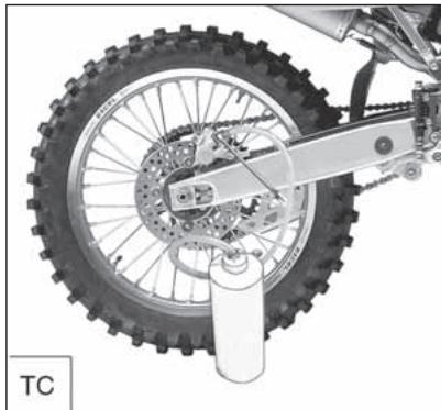
natural_image
Close-up of a motorcycle's front wheel and suspension mechanism (no text or symbols visible)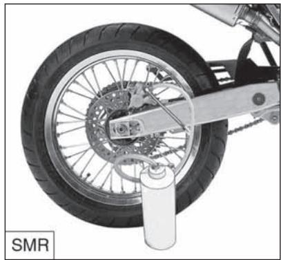
natural_image
Close-up of a motorcycle wheel and suspension mechanism (no text or symbols visible)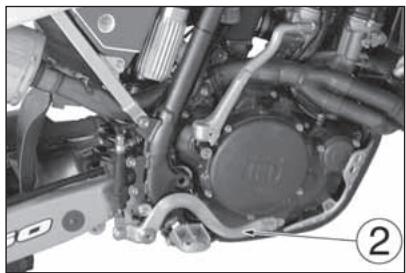
natural_image
Close-up mechanical assembly of a vehicle engine and motor (no visible text or symbols)
natural_image
Close-up of a mechanical assembly with hoses and a labeled component (A), no readable text or symbols present.NOTA
Should the motorcycle, due to a fall during a competition or shop repairs, show some elasticity of the brake lever stroke, with a subsequent braking efficiency decrease, you'll to repeat the circuit bleeding as above described.
AVIS
During the bleed operation the fluid level inside the reservoir must never be lower than the minimum level. Tightening torque for bleed valve is 1,2 ÷ 1,6 kgm ( 12 ÷ 16 Nm; 8.8 ÷ 11.8 ft-lb).
ATTENTION!
The muffler reduces the noise of the exhaust gases, but it is an integral part of the exhaust as well. As such, its conditions affect the motorcycle performance. When the noise on the exhaust is too high, it means that the deadening material set on the holed tube inside the muffler is deteriorated.
WARNING: Check the deadening material after every competition and replace it if necessary.
REPLACING THE MUFFLER DEADENING MATERIAL
First turn counterclockwise fastening rear pin (1) then remove saddle, screws (2) and R.H. side panel (3). Unhook springs (4) fastening the muffler (5) to the exhaust pipes. Remove the two screws fastening the muffler to the rear frame.
Remove the six rear rivets (6), clamp and the exhaust terminal (7). Remove inner pipe and replace the deadening material. Reassemble R.H. side panel and saddle.
NOTE: When difficulties are found in removing the muffler, lightly beat with a rubber or plastic hammer.
SILENCIEUX D'ECHAPPEMENT
natural_image
Diagram of a mechanical component with a numbered callout (1), showing a curved line and a circular feature on top (no text or symbols present)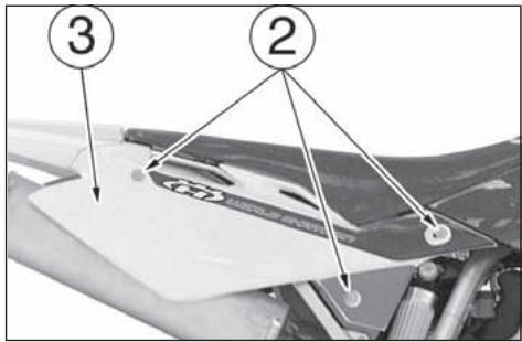
text_image
Diagram of a car hood with numbered annotations pointing to different components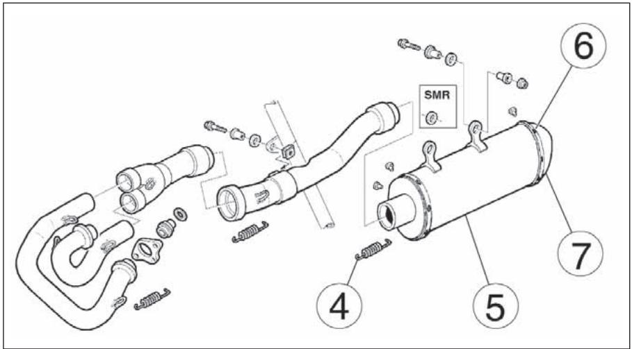
text_image
SMR ④ ⑤ ⑦ ⑥LIMITI DI USURA
NOTA
This chapter shows the main checks to be carried out when the engine and some parts of the byke must be overhauled. More detailed information, together with the disassembly/reassembly procedures are carried in the Husqvarna's Workshop Manual.
CYLINDER-PISTON FITTING
The cylinder and piston are supplied matched; if by chance cylinders and pistons become mismatched then measure their diameters as follows: a) Cylinder bore (Dc) Use an internal micrometer and take the reading “A” at 20 mm-0.8 in. (250 cm ^3 ) or 10 mm-0.4 in. (400-450-510 cm ^3 ) distance from the top.
LIMITE D'USURE
AVIS
b) Piston diameter (Dp) Take the piston diameter at "B" distance of 6 mm/0.24 in. (TE-TC 250), 8 mm/0.31 in. (SMR 400), 9 mm/0.35 in. (TC 450-510), 10 mm/0.39 in. (TE-SMR 450) o 11 mm/0.43 in. (TE-SMR 510) dalla base.
PISTON RING/PISTON RINGS GROOVE CLEARANCE
Use a feeler gauge to check the axial play (H) of the rings in the groove.
The "TOP" marking should always be uppermost.
SEGMENTS-RAINURE SUR LE PISTON
natural_image
Close-up of hands assembling a mechanical component (no visible text or symbols)
PISTON RING/CYLINDER CLEARANCE
Inser the piston ring into the cylinder top (hold the piston ring with the piston), position it well in "square" and measure the distance (A) between the two piston ring end gap.
COUPLAGE SEGMENTS-CYLINDRE
When assembling, the coupling play must be 0.012÷0.027 mm.
The maximum wear limit allowed is 0.055 mm.
ACCOUPLEMENT GOUJON-PIED DE BIELLE
natural_image
Technical line drawing of a mechanical assembly (no text or symbols visible)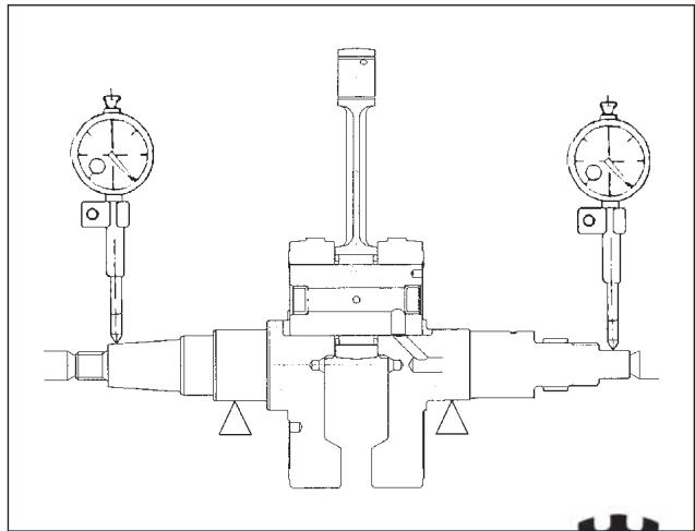
natural_image
Technical line drawing of a mechanical device with three gauges and central actuator (no text or symbols)DISCHI FRIZIONE
The clutch plates should not be burnt or scored. Check the thickness of the clutch lining plate.
Thickness of new plate: 3 mm (0.118 in.).
Wear limit 2,9 mm (0.114 in.)
GROUPE D'EMBRAYAGE
natural_image
Illustration of two hands adjusting a mechanical component with a caliper (no text or symbols present)Check the distortion of each plate (both lined and unlined) by resting on a flat surface; use a feeler gauge. Wear limit: 0,2 mm (0.00078 in.).
natural_image
Illustration of hands operating a mechanical component with a tool, no text or symbols present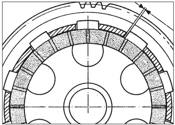
natural_image
Technical diagram of a mechanical gear or cam mechanism with concentric circular components and hatched areas indicating material sections (no text or labels)MOLLA FRIZIONE
Measure the free length “L” of each spring using a gauge. “L” new spring = 41 mm/ 1.61 in. Service limit: 39 mm/ 1.53 in.
RESSORT D'EMBRAYAGE
Accurately check the valve guide. A dial comparator set in a way to determine the play in both "X" and "Y" directions, which are perpendicular to one another, is used to detect the wear on the coupling between the guide and the valve. New intake valve standard play: 0,008-0,035 mm/ 0.00031-0.00138 in. Service limit: 0,05 mm/ 0.002 in.
New exhaust valve standard play: 0,018-0,045 mm/ 0.0007-0.00177 in. Service limit: 0,08 mm/ 0.003 in.
GUIDE-SOUPAPE
Check that the valve shank and the contact surface with the valve seat are in perfect conditions. Pittings, cracks, or any other deformation or wear must not appear on these elements.
Carry out the following checks: - deformation of the valve shank by setting the shank on a "V" striker, and measuring the extent of the deformation by a comparator.
Working limit: 0.05 mm (0.00197 in.).
SOUPAPE
natural_image
Line drawing of a mechanical device with a dial and base mount (no text or symbols)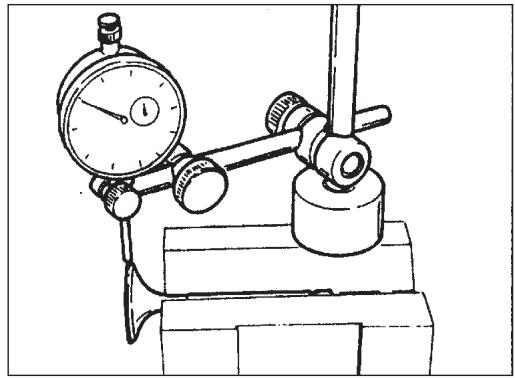
natural_image
Technical line drawing of a mechanical testing setup with a dial gauge and pressure gauge mounted on a base (no text or symbols)MOLLA VALVOLA
The weakening of the springs causes a decrease of the engine power and it often is responsible of the noise and the vibrations coming from the valves. In this case, check the free length “L”. When the working limit indicated has been overcomed, replace the springs. “L” new spring = 35 mm/ 1.38 in. (250); 43,4 mm/ 1.71 in. (400-450-510) Service limit: 33 mm/ 1.3 in. (250); 41 mm/ 1.6 in. (400-450-510)
NOTE:
Replace all the spring valves when even one of these has overcomed the the working limit. Check the spring valve squareness. Error limit not above 1.5 mm (0.059 in.) on each side.
RESSORT DE SOUPAPE
natural_image
Technical line drawing of a mechanical component with threaded sections and a L-shaped outline (no text or symbols)ALBERO A CAMME
Check that cam surfaces are scored, stepped, grooved etc. Insert the camshaft between two references and then check deviation using two comparators. Wear limit: 0.0039 in. Check that the cams are in good conditions, without wear or deformation.
Cam height "H"
INTAKE (new) = 36,57 mm/ 1.44 in.
EXHAUST (new) = 35,94 mm/1.41 in.
ARBRE A CAMES
natural_image
Technical drawing of a mechanical assembly with shafts and housing (no text or labels)EXHAUST
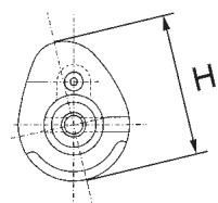
text_image
H
natural_image
Technical mechanical drawing of a shaft assembly (no text or labels)REVISIONE RUOTE
OVERHAULING THE WHEELS
The tables hereunder show the type of control the rim and wheel axle are to be submitted to.
REVISION DES ROUES
Note*: if the rim is badly, it should be replaced.
natural_image
Technical line drawing of a mechanical device with dual scales and adjustment knobs (no text or symbols)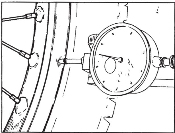
natural_image
Technical line drawing of a pressure gauge mounted on a mechanical component (no text or symbols)PIEGATURA PERNO RUOTA
If the bending figure is over the allowable max. limit, straighten or replace the axle. If the wheel axle cannot be straightened within the max. limits (0,2 mm - 0.008 in.) stated, replace it.
COURBURE PIVOT ROUE
Check to make sure that all the nipples are tight; tighten them if necessary. Remember that an insufficient stretch jeopardizes the motorcycle stability. For an instant check, use a metal point (for instance, a screwdriver) to beat the spokes with. A live sound accounts for an accurate tightening, while a dull sound means that a new tightening is necessary.
RAYONS DE ROUE
natural_image
Illustration of a hand using a tool to measure a mechanical device with a dial and test tube (no text or symbols)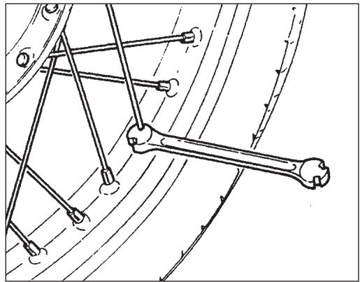
natural_image
Technical line drawing of mechanical linkage components (no text or symbols)IMPIANTO ACCENSIONE (TC-TE-SMR) IMPIANTO ELETTRICO (TE-SMR)
The ignition system includes the following elements:
- Generator (1) on the inner side of L.H. crankcase cover;
- Electronic coil (2) under the fuel tank;
- Electronic power unit (3) under the saddle;
- Voltage regulator (4) on the right side of the frame at the back of the steering sleeve (TE-SMR);
- Spark plug (5) on the R.H. side of cylinder head;
- Starting motor 12V-450W (6) behind the cylinder (TE-SMR);
- Electric start remote control switch (8) under the saddle (TE-SMR);
- Condenser (10) under the saddle. The electric system includes the following elements:
- Headlamp with two filaments bulb of 12V-35/35W and parking light bulb of 12V-3W;
- Rear lights with stop bulbs of 12V-21W and parking light bulb of 12V-5W;
- Pilot lights bulb of 12V-1,2W;
- Turn signals bulb of 12V-10W;
- Instrument bulb of 12V-2W;
- Three15 A fuses (9) (one of them is a spare fuse), under the saddle;
- Battery 12V-6Ah (7) under the saddle.
SYSTEME D'ALLUMAGE (TC-TE-SMR) SYSTEME ÉLECTRIQUE (TE-SMR)
text_image
Technical diagram of a mechanical assembly with numbered annotations pointing to components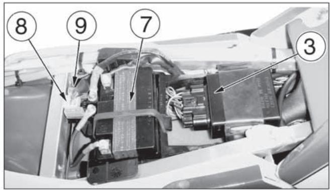
text_image
Labeled diagram of an electronic device interior with numbered components and wiring connections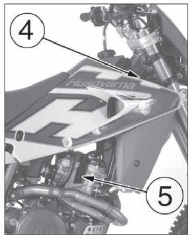
text_image
Hurveirna ④ ⑤
text_image
Technical diagram of a car engine showing labeled parts with numbered annotations| Pos. Pos. | Colore Colour |
| B | Blu/ Blue/ Bleu/ Blau/ Azul |
| Br | Marrone/ Brown/ Maron/ Braun/ Castano |
| Bk | Nero/ Black/ Noir/ Schwarz/ Negro |
| G | Verde/ Green/ Vert/ Grün/ Verd |
| Gr | Grigio/ Grey/ Gris/ Grau/ Gris |
| Y | Giallo/ Yellow/ Jaune/ Gelb/ Amarillo |
| O | Arancio/ Orange/ Orange/ Orange/ Arancio |
| P | Rosa/ Pink/ Rosa/ Rose/ Rosa |
| R | Rosso/ Red/ Rouge/ Rot/ Rojo |
| Sb | Azzurro/ Sky blue/ Azur/ Hellblau/ Celeste |
| V | Viola/ Violet/ Violet / Violett / Viola |
| W | Bianco/ White/ Blanc/ Weiss/ Blanco |
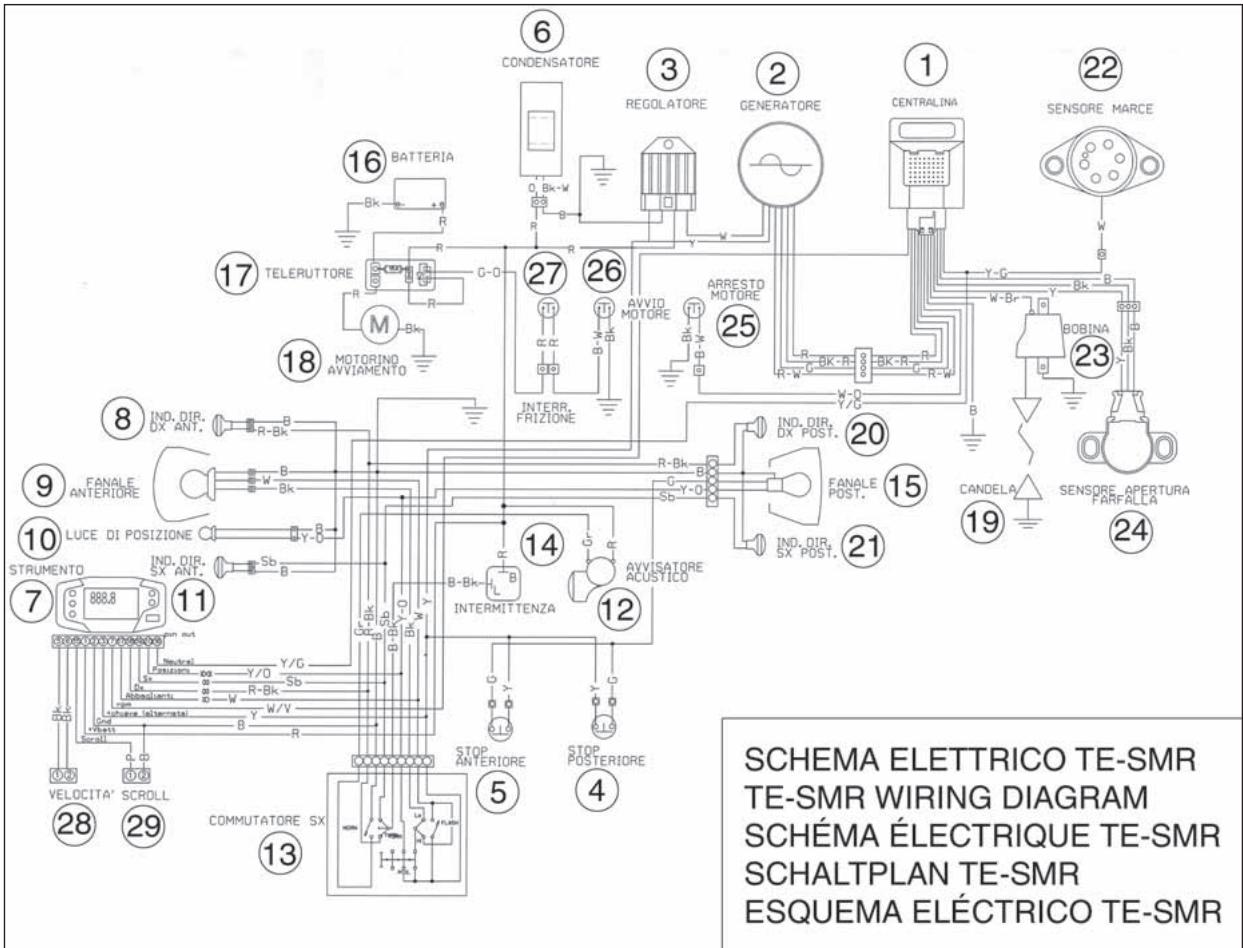
text_image
SCHEMA ELETTRICO TE-SMR TE-SMR WIRING DIAGRAM SCHÉMA ÉLECTRIQUE TE-SMR SCHALTPLAN TE-SMR ESQUEMA ÉLECTRICO TE-SMRLEGENDA SCHEMA ELETTRICO (TE -SMR)
-
Electronic power unit
-
Alternator
-
Voltage regulator
-
Rear stop switch
-
Front stop switch
-
Condenser
-
Instrument
-
R.H. front turn indicator
-
Front headlamp
-
Parking lights
-
L.H. front turn indicator
-
Horn
-
L.H. commutator
-
Turn indicators flasher
-
Tail light
-
Battery
-
Electric start remote control switch
-
Starting motor
-
Spark plug
-
R.H. rear turn indicator
-
L.H. rear turn indicator
-
Gear shift position sen- sor
-
Electronic coil
-
Carburetor throttle position sensor
-
Engine stop
-
Engine start
-
Clutch microswitch
-
Speed
-
Scroll
LÉGENDE DU SCHÉMA ÉLECTRIQUE (TE -SMR)
- Electronic power unit
- Alternator
- Voltage regulator
- Condenser
- Battery
- Electric start remote control switch
- Starting motor
- Spark plug
- Gear shift position sensor
- Electronic coil
- Carburetor throttle position sensor
- Engine stop
- Engine start
- Clutch microswitch
LÉGENDE DU SCHÉMA ÉLECTRIQUE (TC 250)
- Electronic power unit
- Alternator
- Voltage regulator
- Condenser
- Battery
- Electric start remote control switch
- Starting motor
- Spark plug
- Gear shift position sensor
- Electronic coil
- Carburetor throttle position sensor
- Engine stop
- Engine start
- Clutch microswitch
LÉGENDE DU SCHÉMA
ÉLECTRIQUE (TC 450-510)
The sealed battery does not require any maintenance work. When electrolyte leaks, or other failures to the electrical system are detected, apply to the HUSQVARNA Dealer.
If the vehicle remains unused for long periods, it is recommended to remove battery from electrical system and store it in a dry place.
- After an intensive use of the battery, it's advisable a standard low charge (12V-6Ah battery: 0.6A for 8 hours).
- Rapid recharging is advised only in situations of extreme necessity since the life of lead elements is drastically reduced (6A for 0.5 hours with 12V-6Ah batteries).
BATTERY CHARGER
To gain access to the battery (3):
- first turn counterclockwise fastening rear pin (1) then remove the saddle;
● release elastic (2); - first remove the BLACK negative cable, then the RED positive cable (when reassembling, first connect the RED positive cable, then the BLACK negative cable);
- remove the battery (3) from its housing.
BATTERIE
text_image
Labeled mechanical assembly diagram showing components numbered 2 and 3 in a vehicle interiorCheck, using a voltmeter, that battery voltage is not less than 12,5 V. If not, the battery needs to be charged.
Using a battery charter with a constant voltage, first connect the RED positive cable to the battery's positive terminal then the BLACK negative cable to the battery's negative terminal. Apply to the constant voltage of 14,4 V a current of "x" Ampere as results in the below diagram (depending on the amount of charging required).
The voltage reaches a constant value only after a few hours, therefore it is suggested NOT to measure it immediately after having charged or discharged the battery.
Always check the charge level before reinstalling it on the vehicle.
The battery should be kept clean and the terminals coated with grease.
WARNING*: The battery contains sulfuric acid. Avoid contact with skin, eyes or clothing. Antidote: EXTERNAL - Flush with water. INTERNAL - Drink large quantities of water or milk. After milk take magnesia, beaten eggs or vegetable oil. Call physician immediately. Eyes: Flush with water for no less than 15 minutes and get prompt medical attention.
WARNING*: Batteries produce explosive gas, ventilate when charging or using in enclosed space. When using a battery charger before turning on the charger. This procedure prevents sparks at the battery terminals which could ignite any battery gases.
natural_image
Interior view of a vehicle showing battery pack, charging module, and engine compartment (no visible text or symbols)SOSTITUZIONE LAMPADINE PROIETTORE (TE-SMR)
REPLACEMENT (TE-SMR)
To gain access to the healamp bulbs, proceed as follows:
- remove the two fastening elastics (1) and the headlamp holder;
- remove the two filaments bulb connector; (2) and the boot (3)
- release the bulb holding spring (4) and then the bulb itself.
REMLACEMENT DES
AMPOULES DU PHARE AVANT (TE-SMR)
To replace the parking light bulb, (5) extract it from the inside cover. After replacement, reverse operations for reassembly.
natural_image
Close-up of a motorcycle's front suspension system with labeled component (no readable text or symbols)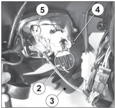
text_image
Labeled diagram of a vehicle interior showing numbered components and structural elementsSOSTITUZIONE LAMPADA FANALE POSTERIORE (TE- SMR)
Remove the two fastening screws (1) in the inner side of the rear fender and the lens (2). Pull the lamp (3) inside, turn it counterclockwise then remove it from the lamp holder.
After replacement, reverse operations for reassembly.
NOTES: make sure not to tighten the screws excessively.
REMPLACEMENT DES AMPOULES DU PHARE ARRIÈRE (TE- SMR)
natural_image
Close-up of a metal bracket with a numbered annotation (1) pointing to a specific feature, no readable text or symbols present.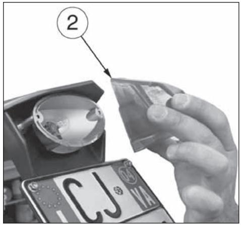
text_image
② CJ VA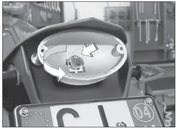
natural_image
Close-up of a motorcycle's front bumper with a circular component and directional arrows indicating motion (no text or symbols)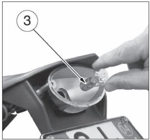
text_image
③REGISTRAZIONE FANALE ANTERIORE (TE, SMR)
ADJUSTMENT OF HEADLIGHT (TE, SMR)
When checking the proper orienting of headlight, inflate tires at right pressure, sat a person on the saddle and place the motorcycle perpendicular with its longitudinal axis 10 meters (33 ft) from a wall or screen. Then trace an horizontal line equal to the height of headlight center and a vertical one in line with its longitudinal axis. If possible, execute this operation in a shadowy place. When the low beam is on, the upper boundary limit between dark and lit zone should be 9/10 th of headlight center from ground.
REGLAGE DU PHARE (TE, SMR)
Adjust the preadlamp aiming by turning screw (1) to lower or lift the high beam.
The motorcycle comes with the following tools:
1-8000 66802
Box wrench 15x27mm (TE-TC-SMR)
2-8000 96997
Front wheel axle wrench (TC)
3-8000 56920
Front wheel axle screw Allen wrench (TC)
4-8000 A4349
Spark plug wrench
(TE-TC-SMR)
DOTATION D'OUTILS
Ringschlüssel15x27mm
(TE-TC-SMR)
2-8000 96997
natural_image
Close-up of a car's head panel showing a transparent dome and a small object, with no visible text or symbols.
text_image
Technical diagram showing four labeled parts of a wrench tool, including handle, shaft, and end cap.| ATTREZZI SPECIALI | SPECIAL TOOLS | OUTILS SPECIAUX | SONDERWERKZEUGE | HERRAMIENTAS ESPECIALES | ||
| 1 | 1517 94702 | Estrattore basamento | Crankcase puller | Extracteur carter | Kurbelgehäuse-Auszieher | Extractor cárter |
| 2 | 8000 A1580 | Protezione alb. motore | Crankshaft guard | Protection vilebrequin | Schutz für Kurbewelle | Protección por cigueñal |
| 3 | 8000 A1559 | Estrattore volano | Flywheel extractor | Extracteur pour volant | Auszieher für Schwungrad | Extractor volante |
| 4 | 8000 A1512 | Attrezzo contr. accensione | Ignition checking tool | Outil contrôle allumage | Kontrollwerkzeug für Zundung | Herramienta control encendido |
| 5 | 8A00 90622 | Supporto per montaggio | Support for assy | Support pour montage | Halterung für Montage | Soporte por el montaje |
| 6 | 8000 A1576 | Attrezzo mont. semiconi | Half cone assembling tool | Outil montage demi-cône | Werkzeug für montage | Herramienta porta comparador |
| 7 | 8000 A1625 | Attrezzo portacomparatore | Dial gauge holding tool | Outil support comparateur | Werkzeug Komparatorhalter | Herramienta porta comparador |
| 8 | 8000 A1579 | Attrezzo smont. semiconi | Half cone disassembling tool | Outil demontage demi-cône | Werkzeug für Ausbau der Half-Kebel | Herramienta desmontaje semi-conos |
| 9 | 8000 79015 | Chiave di fermo mozzo frizione | Clutch hub retaining wrench | Cléf d'arret moyeau embrayage | Halterungsschlussel der | Llave bloquear cubo |
| 10 | 1519 84701 | Gancio per molle | Spring hook | Crochet pour ressort | Federhaken | Gancho para resorte |
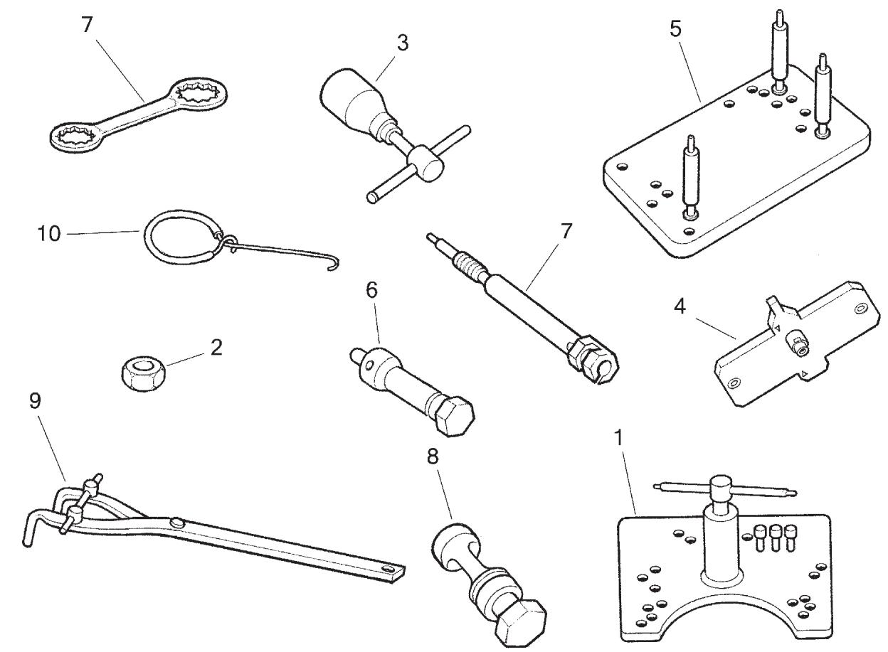
COPPIE DI SERRAGGIO / TIGHTENING TORQUES / COUPLES DE SERRAGE
| MOTORE | ENGINE | MOTEUR |
| Applicazione | Application | Application |
| Vite fiss. cappello albero a camme | Camshaft cap fastening screw | Vis de fixation capuchon arbre distribution |
| Tappo perno bilanciere | Rocker arm axle plug | Bouchon axle culbuteur |
| Vite fiss. coperchio testa | Cylinder head cover fastening screw | Vis de fixation couvercle culasse cylindre |
| Dado fiss. testa | Cylinder head fastening nut | Ecrou de fixation culasse cylindre |
| Dado fiss. testa e cilindro | Cylinder head and cylinder fastening nut | Ecrou de fixation culasse et cylindre |
| Vite fiss. tubo olio sulla testa cilindro | Oil hose to cylinder head fastening screw | Vis de fixation tuyau huile sur la culasse cylindre |
| Tappo foro olio su perno di biella | Oil hole plug on conrod pin | Bouchon pour trou huile sur pivot de bielle |
| Dado fiss. ingr. conduttore trasm. primaria | Primary drive driving gear fastening nut | Ecrou de fixation engrenage conducteur transm. primaire |
| Vite fiss. disco centrifugo su albero a camme ASPIRAZIONE | Centrifugal disc on INTAKE CAMSHAFT fastening screw | Vis de fixation disque sur arbre distribution (ADMISSION) |
| Vite fiss. pattino catena distribuzione | Timing chain slider fastening screw | Vis de fixation glissière chaine distribution |
| Vite fiss. piastrine ritegno cuscinetti basamento | Crankcase bearings plates fastening screw | Vis de fixation plaquettes roulements carters |
| Tappo scarico olio motore | Engine oil drain plug | Bouchon de vidange huile moteur |
| Tappo filtro olio motore | Engine oil filter plug | Bouchon filtre huile moteur |
| Vite fiss. coperchio filtro olio | Engine oil filter cartridge cover fastening screw | Vis de fixation couvercle filtre huile |
| Vite fiss. cornetto carburatore | Carburetor union fastening screw | Vis de fixation manchon carburateur |
| Dado fiss. alternatore | Alternator fastening nut | Ecrou de fixation alternateur |
| Vite fiss. statore | Stator plate fastening screw | Vis de fixation stator |
| Candela accensione | Spark plug | Bougie d'allumage |
| Vite fiss. pick-up | Pick-up fastening screw | Vis de fixation pick-up |
| Dado fiss. mozzo e campana frizione | Clutch hub and disc housing fastening nut | Ecrou de fixation moyeau et cage embrayage |
| Vite fiss. piastra ritegno ingranaggi avviamento | Starting gears stop plate fastening screw | Vis de fixation plaque engrenage démarrage |
| Vite fiss. tamburo selettore | Gearbox forks driving shaft fastening screw | Vis de fixation tambour selecteur |
| Vite fiss. saltarello e piastra comando cambio | Gear control click and plate fastening screw | Vis de fixation cliquet et plaque commande de vitesse |
| Vite fiss. segnalatore marce | Gear shift position sensor fastening screw | Vis de fixation signaleur de vitesse |
| Dado fiss. girante pompa acqua | Water pump rotor fastening nut | Ecrou de fixation couronne pompe eau |
| Vite fiss. corpo pompa acqua | Water pump body fastening screw | Vis de fixation corps pompe eau |
| Vite fiss. piastrina anello di tenuta per pignone uscita cambio | Drive sprocket seal ring plate fastening screw | Vis de fixation plaquette bague de retenue pignon sortie boîte de vitesse |
VERSCHRAUBUNGSMOMENTE / PATAS DE TORSION
| MOTOR | Filettatura Threading Filetate Gewinde Filetado | ± 5% | |||
| Anwendung | Aplicación | ||||
| Befestigungsschraube Nockenwelle Kappe | Tuerca fijación caballete eje distribución | M6x1 | 12 Nm | 1,2 Kgm | 8.7 ft/lb |
| Kipphebelachse Verschluss | Tapón perno balancin | M14x1,5 (+LOCTITE 243) | 25 Nm | 2,55 Kgm | 18.4 ft/lb |
| Befestigungsschraube Zylinderdeckel | Tornillo fijación tapa culata | M6x1 | 8 Nm | 0,8 Kgm | 5.8 ft/lb |
| Befestigungsmutter Zylinderkopf | Tuerca fijación culata | M8x1,25 | 15 Nm | 1,5 Kgm | 10.8 ft/lb |
| Befestigungsmutter Kopf und Zylinder | Tuerca fijación culata y cilindro | M10x1,5 (+MOLIKOTE HSC) | 37 Nm+90° | 3.8 Nm+90° | 27.5 ft/lb+90° |
| Befestigungsschraube Ölrohr-Zylinderkopf | Tornillo fijación tubo aceite en la culata | M10x1 | 15 Nm | 1,5 Kgm | 10.8 ft/lb |
| Ölstopfen auf der Kurbelzapfen | Tapón oroficio aceite su perno de biela | M14x1 (+LOCTITE 243) | 20 Nm | 2 Kgm | 14.5 ft/lb |
| Befestigungsmutter Antriebsrad | Tuerca fijación engranaje conductor transm. primaria | M18x1,25 (+LOCTITE 243) | 180 Nm | 18 Kgm | 130 ft/lb |
| Befestigungsschraube Scheibe für Nockenwelle (ANSAUGSEITE) | Tornillo fijación disco en el eje distribución (ASPIRACION) | M6x1 (+LOCTITE 243) | 8 Nm | 0,8 Kgm | 5.8 ft/lb |
| Befestigungsschraube Ventilsteuerungkette Gleitbahn | Tornillo fijación plado cadena distribución | M8x1,25 | 12 Nm | 1,23 Kgm | 8.9 ft/lb |
| Befestigungsschraube Gehauselager Platte | Tornillo fijación placa cojinete de carter | M6x1 (+LOCTITE 272) | 11 Nm | 1,1 Kgm | 7.9 ft/lb |
| Motorölablaßstopfen | Tapón vaciado aceite motor | M16x1,5 | 25 Nm | 2,55 Kgm | 18.4 ft/lb |
| Motorölfilter Verschluss | Tapón filtro aceite motor | M14x1,5 | 25 Nm | 2,55 Kgm | 18.4 ft/lb |
| Befestigungsschraube Wechselfilterdeckel | Tornillo fijación tapa filtro aceite | M5x0,8 (+LOCTITE 243) | 6 Nm | 0,6 Kgm | 4.3 ft/lb |
| Befestigungsschraube Vergasermuffe | Tornillo fijación tubo toma aire carburador | M4x0,7 (+LOCTITE 272) | 3 Nm | 0,3 Kgm | 2.2 ft/lb |
| Befestigungsmutter Alternator | Tuerca fijación alternador | M12x1 | 75 Nm | 7,65 Kgm | 55.3 ft/lb |
| Befestigungsschraube Stator | Tornillo fijación estator | M6x1 (+LOCTITE 272) | 8 Nm | 0,8 Kgm | 5.8 ft/lb |
| Zündkerze | Bujia de encendido | M10x1 | 10÷12 Nm | 0,98÷1,23 Kgm | 7.4÷8.9 ft/lb. |
| Befestigungsschraube Pick-up | Tornillo fijación pick-up | M5x0,8 (+LOCTITE 272) | 6 Nm | 0,6 Kgm | 4.3 ft/lb |
| Befestigungsmutter Kupplungscheibenhalternabe und Kupplungkorb | Tuerca fijación cubo y campana embrague | M18x1 | 75 Nm | 7,6 Kgm | 55 ft/lb |
| Befestigungsschraube Anlasserantriebsrad Platte | Tornillo fijación placa engrenaje de arranque | M6x1 (+LOCTITE 243) | 8 Nm | 0,8 Kgm | 5.8 ft/lb |
| Befestigungsschraube Trommel | Tornillo fijación. tambor selector | M8x1,25 (+LOCTITE 243) | 20 Nm | 2 Kgm | 14.5 ft/lb |
| Befestigungsschraube Strumhaken und Gangschaltung Platte | Tornillo fijación saltarelo y placa mando cambio | M6x1 (+LOCTITE 243) | 8 Nm | 0,8 Kgm | 5.8 ft/lb |
| Befestigungsschraube Gangkontrol | Tornillo fijación señalador velocidad | M5x0,8 (+LOCTITE 243) | 6 Nm | 0,6 Kgm | 4.3 ft/lb |
| Befestigungsmutter Wasserpumprotor | Tuerca fijación rotor bomba agua | M5x0,8 (+LOCTITE 243) | 3,9 Nm | 0,4 Kgm | 2.9 ft/lb |
| Befestigungsschraube Wasserpumpkörper | Tornillo fijación corpo bomba agua | M6x1(+LOCTITE 542) | 8 Nm | 0,8 Kgm | 5.8 ft/lb |
| Befestigungsschraube für Dichtringsplatte von Abtriebritzel | Tornillo fijación placa anillo de retención piñón salida cambio | M5x0,8 (+LOCTITE 243) | 6 Nm | 0,6 Kgm | 4.3 ft/lb |
COPPIE DI SERRAGGIO / TIGHTENING TORQUES / COUPLES DE SERRAGE
| MOTOTELAIO | CHASSIS | CHASSIS |
| Applicazione | Application | Application |
| Vite fiss. inferiore telaio posteriore | Rear frame lower fastening screw | Vis de fixation inferieur cadre arrière |
| Vite fiss. protezione motore | Engine guard fastening screw | Vis de fixation protection moteur |
| Vite fiss. rullo catena | Rear chain roller fastening screw | Vis de fixation rouleau chaine |
| Vite fiss. cavalletto laterale | Side stand fastening screw | Vis de fixation bequille lateral |
| Vite fiss. superiore telaio posteriore | Rear frame upper fastening screw | Vis de fixation superieur cadre arrière |
| Vite fiss.telaio-piastra motore | Frame to engine plate fastening screw | Vis de fixation cadre - plaque moteur |
| Vite fiss. inferiore motore | Engine lower fastening screw | Vis de fixation inferieur moteur |
| Vite fiss. cavallotti frizione e freno anteriore | Clutch and front brake controls clamp fastening screw | Vis de fixation cavaliers embrague et frein avant |
| Vite fiss. supporti comando gas | Throttle control holders fastening screw | Vis de fixation supports commande gaz |
| Vite fiss. superiore tubazione freno anteriore (TE, SMR) | Front brake hose upper fastening screw (TE, SMR) | Vis de fixation superieur tuyau frein avant (TE, SMR) |
| Vite fiss. superiore tubazione freno anteriore (TC) | Front brake hose upper fastening screw (TC) | Vis de fixation superieur tuyau frein avant (TC) |
| Vite fiss. pedale freno posteriore | Rear brake control pedal fastening screw | Vis de fixation pédale frein arrière |
| Vite fiss. pompa freno posteriore | Rear brake pump fastening screw | Vis de fixation pompe frein arrière |
| Vite fiss. piastrina pompa freno anteriore (SMR) | Front brake pump plate fastening screw (SMR) | Vis de fixation plaque pompe frein avant (SMR) |
| Vite fiss. serbatoio liquido freno posteriore | Rear brake fluid tank fastening screw | Vis de fixation réservoir liquide frein arrière |
| Interruttore stop posteriore (TE, SMR) | Rear stop control switch (TE, SMR) | Interrupteur stop arrière (TE, SMR) |
| Vite fiss. connettore interruttore stop anteriore (SMR) | Front control switch connector fastening screw (SMR) | Vis de fixation connecteur Interrupteur stop avant (SMR) |
| Vite fiss. camma pedale freno posteriore | Rear brake pedal adjusting cam fastening screw | Vis de fixation came pédale frein arrière |
| Vite fiss. piastrina guidatubazione freno anteriore | Front brake hose guide plate fastening screw | Vis de fixation plaque guide tuyau frein avant |
| Vite fiss. tappo serbatoio freno anteriore (SMR) | Front brake tank cap fastening screw (SMR) | Vis de fixation bouchon réservoir frein avant (SMR) |
| Vite fiss. gambe forcella | Front fork legs fastening screw | Vis de fixation tige fourche avant |
| Vite fiss. perno ruota anteriore | Front wheel axle fastening screw | Vis de fixation piovot roue avant |
| Ghiera registro cuscinetti di sterzo | Steering bearings adjusting ring nut | Collier de réglage roulement guidon |
| Dado perno di sterzo | Steering pivot fastening nut | Ecrou de fixation pivot guidon |
| Vite fiss. morsetto superiore manubrio | Handlebar upper clamp | Vis de fixation etau superieur guidon |
| Vite fiss. supporto manubrio | Handlebar holder fastening screw | Vis de fixation support guidon |
| Vite fiss. protezioni steli forcella | Front fork legs guard fastening screw | Vis de fixation protection tige fourche avant |
| Vite fiss. anelli protezioni steli forcella | Front fork legs ring guard fastening screw | Vis de fixation bague protection tige fourche avant |
| Dado fiss. perno forcellone | Rear swing arm axle fastening nut | Ecrou de fixation pivot fourche |
| Dado fiss. bilanciere-forcellone | Rear swing arm to rocker arm fastening nut | Ecrou de fixation balancier- fourche arrière |
| Dado fiss. tirante-bilanciere | Tie rod to rocker arm fastening nut | Ecrou de fixation tirant- balancier |
VERSCHRAUBUNGSMOMENTE / PATAS DE TORSION
| CHASSIS | |||||
| Chassis Aplicación | CHASSIS Aplicación | Filettatura Threading Filetate Gewinde Filetado | ±5% | ||
| Befestigungsschraube Hinterrahmen (untere) | Tornillo fijación inferior bastidor trasero | M8x1,25 | 25,5 Nm | 2,6 Kgm | 18.8 ft/lb |
| Befestigungsschraube Motorschutz | Tornillo fijación protección motor | M6x1 | 14,7 Nm | 1,5 Kgm | 10.8 ft/lb |
| Befestigungsschraube Kettenrolle | Tornillo fijación rodeta cadena | M8x1,25 | 26,95 Nm | 2,75 Kgm | 19.9 ft/lb |
| Befestigungsschraube Seitenständer | Tornillo fijación caballete lateral | M8x1,25 (+LOCTITE 243) | 11,75 Nm | 1,2 Kgm | 8.7 ft/lb |
| Befestigungsschraube Hinterrahmen (obere) | Tornillo fijación superior bastidor trasero | M8x1,25 | 25,5 Nm | 2,6 Kgm | 18.8 ft/lb |
| Befestigungsschraube Rahmen-Motorplatte | Tornillo fijación bastidor -placa motor | M8x1,25 (+LOCTITE 270 | 35,3 Nm | 3,6 Kgm | 26 ft/lb |
| Befestigungsschraube Motor (untere) | Tornillo fijación inferior motor | M8x1,25 | 35,3 Nm | 3,6 Kgm | 26 ft/lb |
| Befestigungsschraube Kupplunghalter und Vorderbremse | Tornillo fijación conexiones embrage y freno delantero | M6x1 | 4,9 Nm | 0,5 Kgm | 3.6 ft/lb |
| Befestigungsschraube Gasgriffhalter | Tornillo fijación suportes mando gas | M6x1 | 4,9 Nm | 0,5 Kgm | 3.6 ft/lb |
| Obere Befestigungsschraube Vorderbremserohr (TE, SMR) | Tornillo fijación superior tuberia freno delantero (TE, SMR) | M10x1 | 19 Nm | 1,95 Kgm | 14 ft/lb |
| Obere Befestigungsschraube Vorderbremserohr (TC) | Tornillo fijación superior tuberia freno delantero (TC) | M10x1 | 24,7 Nm | 2,5 Kgm | 18.2 ft/lb |
| Befestigungsschraube Hinterbremsenpedal | Tornillo fijación pedal freno trasero | M10x1,25 (+LOCTITE 243) | 41,65 Nm | 4,25 Kgm | 30.7 ft/lb |
| Befestigungsschraube Hinterbremsenpumpe | Tornillo fijación bomba freno trasero | M6x1 | 10,4 Nm | 1,05 Kgm | 7.7 ft/lb |
| Befestigungsschraube Vorderbremsenpumpeplatte (SMR) | Tornillo fijación placa bomba freno delantero (SMR) | M6x1 | 10,4 Nm | 1,05 Kgm | 7.7 ft/lb |
| Befestigungsschraube Hinterbremseöltank | Tornillo fijación deposito líquido freno trasero | M6x1 | 2,45 Nm | 0,25 Kgm | 1.8 ft/lb |
| Schalter Hinterradbremslicht (TE, SMR) | Interruptor stop trasero (TE, SMR) | M10x1 | 19 Nm | 1,95 Kgm | 14 ft/lb |
| Befestigungsschraube Verbinder für Schalter Vorderradbremslicht (SMR) | Tornillo fijación conector interruptor stop delantero (SMR) | M2x0,4 | 0,8 Nm | 0,1 Kgm | 0,6 ft/lb |
| Befestigungsschraube Hinterbremse Pedalnocken | Tornillo fijación excéntrico pedal freno trasero | M6x1 | 14,7 Nm | 1,4 Kgm | 10.8 ft/lb |
| Befestigungsschraube Rohrplatte Vorderbremse | Tornillo fijación placa guía-tuberia freno delantero | M6x1 | 6 Nm | 0,6 Kgm | 4.4 ft/lb |
| Befestigungsschraube Vorderbremse Öltankstöpsel (SMR) | Tornillo fijación tapón deposito freno delantero (SMR) | M6x1 | 4,9 Nm | 0,5 Kgm | 3.6 ft/lb |
| Befestigungsschraube Vordergabelschafte | Tornillo fijación varillas horquilla delantera | M8x1,25 | 25 Nm | 2,5 Kgm | 18.4 ft/lb |
| Befestigungsschraube Vorderradzapfen | Tornillo fijación perno rueda delantera | M6x1 | 10,4 Nm | 1,05 Kgm | 7.7 ft/lb |
| Einstellzwinge Lenkungslager | Virola aiuste cojinetes de la guía | M25x1 | 3,45 Nm | 0,35 Kgm | 2.5 ft/lb |
| Befestigungsmutter Lenkbolzen | Tuerca eje de la guía | M24x1 | 83,3 Nm | 8,5 Kgm | 61.4 ft/lb |
| Befestigungsschraube Obere Lenkerklemme | Tornillo fijación abrazadera superior del manillar | M8x1,25 | 28,4 Nm | 2,9 Kgm | 20.9 ft/lb |
| Befestigungsschraube Lenkerhalterung | Tornillo fijación suporte del manillar | M10x1,5 | 21,1 Nm | 2,15 Kgm | 15.6 ft/lb |
| Befestigungsschraube Vordergabelstangen | Tornillo fijación protección varillas horquilla delantera | M5x0,8 | 7,85 Nm | 0,8 Kgm | 5.8 ft/lb |
| Befestigungsschraube Schutzring für Vordergabelstangen | Tornillo fijación anillo protecciones varillas horquilla delantera | M5x0,8 | 2,45 Nm | 0,25 Kgm | 1.8 ft/lb |
| Befestigungsmutter Hintergabelzapfen | Tuerca fijación perno horquilla trasera | M16x1,5 (+LOCTITE 243) | 122,5 Nm | 12,5 Kgm | 90.3 ft/lb |
| Befestigungsmutter Kipphebel-Hintergabel | Tuerca fijación balancín- horquilla trasera | M12x1,25 | 80 Nm | 8,2 Kgm | 59 ft/lb |
| Befestigungsmutter Spannstange- Kipphebel | Tuerca fijación tirante- balancín | M12x1,25 | 80 Nm | 8,2 Kgm | 59 ft/lb |
COPPIE DI SERRAGGIO / TIGHTENING TORQUES / COUPLES DE SERRAGE
| MOTOTELAIO | CHASSIS | CHASSIS |
| Applicazione | Application | Application |
| Dado fiss. telaio-tirante | Frame to tie rod fastening nut | Ecrou de fixation cadre- tirant |
| Ingrassatore | Rocker arm to tie rod lubricator | Graisseur |
| Vite fiss. ammortizzatore-telaio | Rear shock absorber to frame fastening pivot | Vis de fixation amortisseur-cadre |
| Vite fiss. bilanciere- telaio | Rocker arm to frame fastening pivot | Vis de fixation balancier - cadre |
| Vite fiss. guidacatena-forcellone (TE-SMR) | Chain guide to rear swing arm fastening screw (TE-SMR) | Vis de fixation guide-chaine/fourche arrière (TE-SMR) |
| Vite fiss. anteriore guidacatena-forcellone (TC) | Chain guide to rear swing arm front fastening screw (TC) | Vis de fixation avant guide-chaine/fourche arrière (TC) |
| Vite fiss. posteriore guidacatena-forcellone (TC) | Chain guide to rear swing arm rear fastening screw (TC) | Vis de fixation arrière guide-chaine/fourche arrière (TC) |
| Vite fiss. staffa-guidacatena (TE-SMR) | Bracket to chain guide fastening screw (TE-SMR) | Vis de fixation etrier/guide-chaine (TE-SMR) |
| Vite fiss. inf. pattino catena e passatubazione freno posteriore | Chain slider and rear brake hose clamp lower fastening screw | Vis de fixation inf. glissière chaine et passe-tuyau frein arrière |
| Vite fiss. post. pattino catena e passatubazione freno posteriore (TC) | Chain slider and rear brake hose clamp rear fastening screw | Vis de fixation arrière glissière chaine et passe-tuyau frein arrière (TC) |
| Vite fiss. copricatena (TE-SMR) | Chain guard fastening screw (TE-SMR) | Vis de fixation carter de chaine (TE-SMR) |
| Dado fiss. tendicatena | Chain adjuster fastening nut | Ecrou de fixation tendeur de chaine |
| Vite fiss. spoiler a serbatoio | Spoiler to fuel tank fastening screw | Vis de fixation spoiler-réservoir |
| Vite fiss. superiore portanumero anteriore (TC) | Front number holder upper fastening screw (TC) | Vis de fixation superieur porte-numero avant (TC) |
| Vite fiss. inferiore portanumero anteriore (TC) | Front number holder lower fastening screw (TC) | Vis de fixation inferieur porte-numero avant (TC) |
| Vite fiss. protezione ammortizzatore | Rear shock absorber guard fastening screw | Vis de fixation protection amortisseur arrière |
| Vite fiss. anteriore parafango posteriore | Rear fender front fastening screw | Vis de fixation avant garde-bouie arrière |
| Vite fiss. posteriore parafango posteriore | Rear fender rear fastening screw | Vis de fixation arrière garde-bouie arrière |
| Vite fiss. parafango anteriore | Front fender fastening screw | Vis de fixation garde-bouie avant |
| Vite fiss. protezione radiatore | Radiator guard fastening screw | Vis de fixation protection radiateur |
| Vite fiss. pannello laterale | Side panel fastening screw | Vis de fixation panneau lateral |
| Vite fiss. portatarga | License plate fastening screw | Vis de fixation porte-balai |
| Dado fiss. catadiottro posteriore | Rear reflector fastening nut | Ecrou de fixation catadioptrique arrière |
| Vite fiss. anello passatubazione freno al cupolino | Brake hose ring to front fairing fastening screw | Vis de fixation bague passe-tuyau frein au carenage avant |
| Vite fiss. indicatori direzione | Turn signals fastening screw | Vis de fixation clignotant |
| Vite fiss. gruppo ottico anteriore | Front headlamp fastening screw | Vis de fixation gruppo phare avant |
| Vite fiss. cavi teleruttore | Electric start remote control switch cables fastening screw | Vis de fixation cable telerupteur |
| Vite fiss. tampone anteriore serbatoio carburante | Fuel tank front rubber pad fastening screw | Vis de fixation tampon avant réservoir essence |
| Vite fiss. rubinetto serbatoio carburante | Fuel cock fastening screw | Vis de fixation robinet réservoir essence |
| Vite fiss. posteriore serbatoio carburante | Fuel tank rear fastening screw | Vis de fixation arrière réservoir essence |
| Vite fiss. anteriore scatola filtro | Air filter box front fastening screw | Vis de fixation avant scatola filtro |
VERSCHRAUBUNGSMOMENTE / PATAS DE TORSION
| CHASSIS | |||||
| Aplicación | CHASSIS Aplicación | Filettatura Threading Filetate Gewinde Filetado | ±5% | ||
| Befestigungsmutter Rahmen- Kipphebel | Tuerca fijación bastidor -tirante | M12x1,25 | 80 Nm | 8,2 Kgm | 59 ft/lb |
| Fettbüchse | Lubricador suspension trasera | M6x1 | 2,95 Nm | 0,3 Kgm | 2,2 ft/lb |
| Befestigungsschraube Stossdämpfer-Rahmen | Tornillo fijación amortiguador- bastidor | M10x1,25 | 52,4 Nm | 5,35 Kgm | 38,6 ft/lb |
| Befestigungsschraube Kipphebel - Rahmen | Tornillo fijación balancín - bastidor | M10x1,25 | 52,4 Nm | 5,35 Kgm | 38,6 ft/lb |
| Befestigungsschraube Kettenführung- Hintergabel (TE-SMR) | Tornillo fijación guia-cadena- horquilla trasera (TE-SMR) | M8x1,25 | 25 Nm | 2,5 Kgm | 18.4 ft/lb |
| Befestigungsschraube Vordere Kettenführung - Hintergabel (TC) | Tornillo fijación delantera guia-cadena/horquilla trasera (TC) | M8x1,25 (+LOCTITE 243) | 10,4 Nm | 1,05 Kgm | 7.7 ft/lb |
| Befestigungsschraube Hintere Kettenführung - Hintergabel (TC) | Tornillo fijación trasero guia-cadena/horquilla trasera (TC) | M6x1 (+LOCTITE 243) | 10,4 Nm | 1,05 Kgm | 7.7 ft/lb |
| Befestigungsschraube Buegel-Kettenführung (TE-SMR) | Tornillo fijación brida/guia-cadena (TE-SMR) | M6x1 (+LOCTITE 243) | 2 Nm | 0,2 Kgm | 1.5 ft/lb |
| Befestigungsschraube Untere Gleitbahn und Rohrführung für Hinterbremse | Tornillo fijación inferior plato cadena y guía-tuberia freno trasero | M5x0,8 | 4,4 Nm | 0,45 Kgm | 3.2 ft/lb |
| Befestigungsschraube Hintere Gleitbahn und Rohrführung für Hinterbremse (TC) | Tornillo fijación trasero plato cadena y guía-tuberia freno trasero (TC) | M5x0,8 | 4,4 Nm | 0,45 Kgm | 3.2 ft/lb |
| Befestigungsschraube Kettenkasten (TE-SMR) | Tornillo fijación cubre-cadena (TE-SMR) | M5x0,8 | 4,4 Nm | 0,45 Kgm | 3.2 ft/lb |
| Befestigungsmutter Kettenspanner | Tuerca fijación tensor de cadena | M8x1,25 | 4,4 Nm | 0,45 Kgm | 3.2 ft/lb |
| Befestigungsschraube Spoiler-Kraftstoffbehälter | Tornillo fijación spoiler-deposito gasolina | M6x1 | 6 Nm | 0,6 Kgm | 4.4 ft/lb |
| Befestigungsschraube Obere Vordernummerträge (TC) | Tornillo fijación superior portanumero delantero (TC) | M6x1 | 6 Nm | 0,6 Kgm | 4.4 ft/lb |
| Befestigungsschraube Untere Vordernummerträger (TC) | Tornillo fijación inferior portanumero delantero (TC) | M6x1 | 10,4 Nm | 1,05 Kgm | 7.7 ft/lb |
| Befestigungsschraube Stossdämpferschutz | Tornillo fijación protección amortiguador | M6x1 | 6 Nm | 0,6 Kgm | 4.4 ft/lb |
| Befestigungsschraube Vordere Hinterkotflügel | Tornillo fijación delantero guarda-barros delantero | M6x1 | 10,4 Nm | 1,05 Kgm | 7.7 ft/lb |
| Befestigungsschraube Hintere Hinterkotflügel | Tornillo fijación trasero guarda-barros delantero | M6x1 | 6 Nm | 0,6 Kgm | 4.4 ft/lb |
| Befestigungsschraube Vorderkotflügel | Tornillo fijación guarda-barros delantero | M6x1 | 10,4 Nm | 1,05 Kgm | 7.7 ft/lb |
| Befestigungsschraube Kühlerschutz | Tornillo fijación protección radiator | M6x1 | 6 Nm | 0,6 Kgm | 4.4 ft/lb |
| Befestigungsschraube Streifen | Tornillo fijación panel latera | M6x1 | 6 Nm | 0,6 Kgm | 4.4 ft/lb |
| Befestigungsschraube Schildtraeger | Tornillo fijación porta-matrícula | M6x1 | 6 Nm | 0,6 Kgm | 4.4 ft/lb |
| Befestigungsmutter Rückstrahler | Tuerca fijación catafaros trasero | M4x0,7 | 1,9 Nm | 0,2 Kgm | 1.4 ft/lb |
| Befestigungsschraube Bremsenrohrführung für Verkleidung | Tornillo fijación anillo guía-tuberia freno-cúpula delantera | ø 3,5 | 1,9 Nm | 0,2 Kgm | 1.4 ft/lb |
| Befestigungsschraube Blinker | Tornillo fijación intermitentes | M6x1 | 6 Nm | 0,6 Kgm | 4.4 ft/lb |
| Befestigungsschraube Vordere optische Gruppe | Tornillo fijación grupo óptico delantero | ø 3,9 | 1,45 Nm | 0,15 Kgm | 1 ft/lb |
| Befestigungsschraube Kabel für Fernschalter Anlasser | Tornillo fijación cable teleruptor | M6x1 | 10,4 Nm | 1,05 Kgm | 7.7 ft/lb |
| Befestigungsschraube für Kraftstoffbehälter Vordere Stopfen | Tornillo fijación tampón delantero deposito gasolina | M6x1 | 10,4 Nm | 1,05 Kgm | 7.7 ft/lb |
| Befestigungsschraube Treibstoffhahn | Tornillo fijación grifo deposito gasolina | ø5,5 | 2,45 Nm | 0,25 Kgm | 1.8 ft/lb |
| Hinterbefestigungsschraube Kraftstoffbehälter | Tornillo fijación trasero deposito gasolina | M6x1 | 10,4 Nm | 1,05 Kgm | 7.7 ft/lb |
| Befestigungsschraube Vorderfiltergehäuse | Tornillo fijación delantera caja filtro aire | M6x1 | 10,4 Nm | 1,05 Kgm | 7.7 ft/lb |

COPPIE DI SERRAGGIO / TIGHTENING TORQUES / COUPLES DE SERRAGE
| MOTOTELAIO | CHASSIS | CHASSIS |
| Applicazione | Application | Application |
| Dado fiss. flangia scatola filtro | Air filter box flange fastening nut | Ecrou de fixation flangia bôte filtre à air |
| Vite fiss. pinza freno | Front brake caliper fastening screw | Vis de fixation etrier frein |
| Vite fiss. inferiore tubazioni freni | Brake hoses lower fastening screw | Vis de fixation inferieur tuyau freins |
| Vite fiss. perno ruota anteriore (SMR) | Front wheel axle fastening screw (SMR) | Vis de fixation pivot roue |
| Vite fiss. pinza freno | Front brake caliper to caliper holding plate fastening screw (SMR) | Vis de fixation etrier frein |
| Vite fiss. piastra pinza freno alla forcella (SMR) | Brake caliper holding plate to front fork (SMR) | Vis de fixation plaque etrier frein –fourche avant (SMR) |
| Vite fiss. perno ruota (TE-TC) | Front wheel axle fastening screw (TE-TC) | Vis de fixation pivot roue |
| Vite fiss. disco freno anteriore (TE-TC) | Front brake disc fastening screw (TE-TC) | Vis de fixation disque frein |
| Vite fiss. disco freno anteriore (SMR) | Front brake disc fastening screw (SMR) | Vis de fixation disque frein |
| Vite fiss. disco freno posteriore (TE-TC) | Rear brake disc fastening screw (TE-TC) | Vis de fixation disque frein |
| Nipplo per raggio ruota anteriore | Front wheel nipple | Nipplo per raggio roue |
| Nipplo per raggio ruota posteriore | Rear wheel nipple | Nipplo per raggio roue |
| Dado fiss. corona | Rear wheel sprocket fastening nut | Ecrou de fixation couronne arrière |
| Dado perno ruota posteriore | Rear wheel axle fastening nut | Ecrou de fixation pivot roue |
| Perno ruota anteriore | Front wheel axle | Pivot roue avant |
| Vite fiss. coperchio pignone cambio al carter sinistro | Drive sprocket cover fastening screw | Vis de fixation couvercle pignon-carter gauche |
| Vite fiss. silenziatore di scarico | Exhaust silencer fastening screw | Vis de fixation silencieux d'echappement |
| Vite fiss. tubi di scarico alla testa cilindro | Exhaust pipes to cylinder head fastening screw | Vis de fixation tuyau d'echappement au culasse cylindre |
| Vite fiss. strumento | Instrument fastening screw | Vis de fixation instrument |
| Vite fiss. radiatore | Radiator fastening screw | Vis de fixation radiateur |
VERSCHRAUBUNGSMOMENTE / PATAS DE TORSION
| CHASSIS | |||||
| Aplicación | CHASSIS | Filettatura Threading Filetate Gewinde Filetado | ± 5% | ||
| Aplicación | |||||
| Befestigungsmutter Flansch Filtergehäuse | Tuerca fijación brida caja filtro aire | M5x0,8 | 3,45 Nm | 0,35 Kgm | 2.5 ft/lb |
| Befestigungsschraube Vorderradsattel | Tornillo fijación zapata freno delantero | M8x1,25 | 25,5 Nm | 2,6 Kgm | 18.8 ft/lb |
| Untere Befestigungsschraube für Bremsrohr | Tornillo fijación inferior tuberias frenos | M10x1 | 19 Nm | 1,95 Kgm | 14 ft/lb |
| Befestigungsschraube Vorderradzapfen (SMR) | Tornillo fijación perno rueda delantera (SMR) | M10x1,5 | 51,45 Nm | 5,25 Kgm | 38 ft/lb |
| Befestigungsschraube Vorderradbremssattel-Platte (SMR) | Tornillo fijación zapata freno delantero-placa (SMR) | M10x1,5 | 25,5 Nm | 2,6 Kgm | 18.8 ft/lb |
| Befestigungsschraube Vorderradbremssattelplatte-Vordergabel (SMR) | Tornillo fijación placa zapata freno- horquilla (SMR) | M10x1,5 | 25,5 Nm | 2,6 Kgm | 18.8 ft/lb |
| Befestigungsschraube Vorderradzapfen (TE-TC) | Tornillo fijación perno rueda delantera (TE-TC) | M20x1,5 | 51,45 Nm | 5,25 Kgm | 38 ft/lb |
| Befestigungsschraube Vorderradbremsscheibe (TE-TC) | Tornillo fijación disco freno delantero (TE-TC) | M6x1 (LOCTITE 243) | 14,7 Nm | 1,5 Kgm | 10.8 ft/lb |
| Befestigungsschraube Vorderradbremsscheibe (SMR) | Tornillo fijación disco freno delantero (SMR) | M8x1,25 | 34,7 Nm | 3,54 Kgm | 25.6 ft/lb |
| Befestigungsschraube Hinterradbremsscheibe (TE-TC) | Tornillo fijación disco freno trasero (TE-TC) | M6x1 (LOCTITE 243) | 14,7 Nm | 1,5 Kgm | 10.8 ft/lb |
| Befestigungsnippel Vorderrad | Nipple por radio rueda delantera | M4,07x0,75 | 4,4 Nm | 0,45 Kgm | 3.2 ft/lb |
| Befestigungsnippel Hinterrad | Nipple per radio rueda trasera | M4,5x0,75 | 4,4 Nm | 0,45 Kgm | 3.2 ft/lb |
| Befestigungsmutter Hinterkranz | Tuerca fijación corona trasera | M8x1,25 (+LOCTITE 243) | 34,3 Nm | 3,5 Kgm | 25.3 ft/lb |
| Befestigungsmutter Hinterradzapfen | Tuerca fijación perno rueda trasera | M20x1,5 | 142,1 Nm | 14,5 Kgm | 104.8 ft/lb |
| Vorderradzapfen | Perno rueda delantera | M20x1,5 | 142,1 Nm | 14,5 Kgm | 104.8 ft/lb |
| Befestigungsschraube Deckel Ritzel-L. Gehause | Tornillo fijación tapa piñón cambio-carter izquierdo | M6x1 | 10,4 Nm | 1 Kgm | 7.7 ft/lb |
| Befestigungsschraube Abgasschalldämpfer | Tornillo fijación silenciador de escape | M6x1 | 10,4 Nm | 1 Kgm | 7.7 ft/lb |
| Befestigungsschraube Ausapuffrohr-Zylinderkopf | Tornillo fijación tubos de escape alla culata cilindro | M6x1 | 10,4 Nm | 1 Kgm | 7.7 ft/lb |
| Befestigungsschraube Instrumente | Tornillo fijación instrumento | ø4,8 | 3,45 Nm | 0,35 Kgm | 2.5 ft/lb |
| Befestigungsschraube Kühler | Tornillo fijación radiator | M6x1 | 7 Nm | 0,72 Kgm | 5.2 ft/lb |
KIT
| Code No.Nr. CodeCode NrN. Cod. | DENOMINAZIONE | NAME | DESIGNATION | BESHREIBUNG | DENOMINACION | |
| 1 | 8000 A1320 | Kit protezione carter destro (TE-TC) | R.H. crankcase guard kit (TE-TC) | Kit protection couvercle carter D. (TE-TC) | R. Gehausedeckel Schutz Kit (TE-TC) | Kit protección tapa bancada derecha |
| 2 | 8000 A4295 | Kit carburatore KEIHIN 37 (TC 250) RACING | Carburetor KEIHIN 37 Kit (TC 250) RACING | Kit carburateur KEIHIN 37 (TC 250) RACING | Vergaser Kit KEIHIN 37 (TC 250) RACING | Kit carburador KEIHIN 37 (TC 250) RACING |
| 2 | 8000 A6115 | Kit carburatore KEIHIN 37 (TE 250) RACING | Carburetor KEIHIN 37 Kit (TE 250) RACING | Kit carburateur KEIHIN 37 (TE 250) RACING | Vergaser Kit KEIHIN 37 (TE 250) RACING | Kit carburador KEIHIN37 (TE 250) RACING |
| 2 | 8000 A5918 | Kit carburatore KEIHIN 41 (TE-SMR 450/510)- RACING | Carburetor KEIHIN 41 Kit (TE-SMR 450/510)- RACING | Kit carburateur KEIHIN 41 (TE-SMR 450/510)- RACING | Vergaser Kit KEIHIN 41 (TE-SMR 450/510)- RACING | Kit carburador KEIHIN 41 (TE-SMR 450/510)- RACING |
| 2 | 8000 A4296 | Kit carburatore KEIHIN 41 (TC 450/510)-RACING | Carburetor KEIHIN 41 Kit (TC 450/510)-RACING | Kit carburateur KEIHIN 41 (TC 450/510)-RACING | Vergaser Kit KEIHIN 41 (TC 450/510)-RACING | Kit carburador KEIHIN 41 (TC 450/510)-RACING |
| 2 | 8000 A3091 | Kit carburat. MIKUNI 38 (SMR 400)-RACING | Carburetor MIKUNI 38 Kit (SMR 400)-RACING | Kit carburateur MIKUNI 38 (SMR 400)-RACING | Vergaser Kit MIKUNI 38 (SMR 400)-RACING | Kit carburador MIKUNI 38 (SMR 400)-RACING |
| 3 | 8000 A0865 | Paramotore (TE-TC) | Engine guard (TE-TC) | Garde moteur (TE-TC) | Motorschutz (TE-TC) | Para motor (TE-TC) |
| 4 | 8000 A0677 (*) | Kit compl. poggiapiedi (TE-SMR) | Compl. footrest Kit (TE-SMR) | Appui-pied complet (TE-SMR) | kompl. Fussraster-Kit (TE-SMR) | Kit compl. apoyapiés (TE-SMR) |
| 5 | 8B00 A0226 (*) | Kit indicatori di direzione (TE-SMR) | Blinkers Kit (TE-SMR) | Kit clignotants (TE-SMR) | Blinkers Kit (TE-SMR) | Kit intermitentes (TE-SMR) |
| 6 | 8000 A3191 | Kit gancio per la fase di partenza della gara (TC) | Hook Kit for race starting phase (TC) | Kit crochet pour phase de départ de la compétition (TC) | Kit Haken für die Phase von Abreise des Wettkampfes (TC) | Kit gancho por fase de salida de la competición (TC) |
*:Non per USA/CDN - Not for USA/CDN - Ne pas pour USA/CDN-Keine für USA/CDN - No por U.S.
KIT
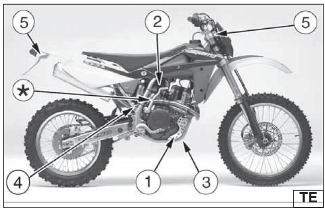
text_image
5 2 5 * 4 1 3 TE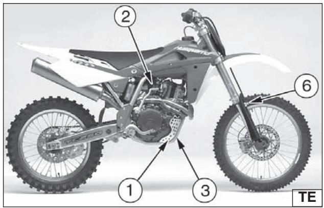
text_image
Labeled diagram of a 200 motorcycle showing key components including wheel, suspension, and suspension parts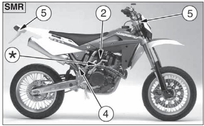
text_image
SMR 5 2 5 * 4*: KIT AVVIAMENTO A PEDALE
*: KICK STARTER KIT
*: KIT DÉMARRAGE À PÉDALE
*: KIT KICKSTARTER
+: KIT ARRANQUE A PEDAL
PARTI OPTIONAL (TE)
| 1- Gruppo anelli di tenuta motore | 8000 99923 |
| 2- Corona posteriore | |
| 8A00 96837 (Z=47) | |
| 8B00 96837 (Z=48) | |
| 8C00 96837 (Z=49) | |
| 8D00 96837 (Z=50)★ | |
| 3- Pignone uscita cambio | |
| 8000 63827 (Z=12) | |
| 8000 63828 (Z=13) § | |
| 8000 63829 (Z=14) & | |
| 8000 63830 (Z=15) |
§: STANDARD on 250-450 model
&: STANDARD on 510 model
ELEMENTS EN OPTION (TE)
text_image
① ② ③ ④ ⑤ ⑥ ⑦ ⑧ ⑨ ⑩ ⑪ ⑫ ⑬PARTI OPTIONAL (TC)
OPTIONAL PARTS LIST (TC)
| 1. Engine seals kit | 8000 99923 |
| 2. Workshop manual | 8000 A5911 |
| 3. Rear sprocket | |
| 8A00 96837 (Z=47) && 8B00 96837 (Z=48) | |
| 8C00 96837 (Z=49) | |
| 8D00 96837 (Z=50) §, & | |
| 4. Drive sprocket | |
| 8000 63827 (Z=12) § | |
| 8000 63828 (Z=13) | |
| 8000 63829 (Z=14) &, && 8000 63830 (Z=15) | |
| 5. Engine basket kit (250) | 8000 A4223 |
| Engine basket kit (450-510) | 8000 A4226 |
| 6. Front fork oil(1000 cm3 container) | 8000 80260 |
| 8-Front fork spring+spacer kit(K=4,8 N/mm) | 8000 98789 * |
| 9-Rear shock absorber spring(K=5 Kg/mm) | 8000 ..... * |
| 10. Spare parts catalogue | 8000 A5912 |
| 11. Brake fluid (250 cm3 container) | 8000 71445 |
| 12. Electric starter kit | 8000 A6487 |
| *: STANDARD | |
| §: STANDARD on 250 model&: STANDARD on 450 model&&: STANDARD on 510 | |
ELEMENTS EN OPTION (TC)
AFTER-RACE CHECK POINTS After racing, first clean the motorcycle and then inspect the entire motorcycle, with special attention to the items listed in «MAIN-TENANCE» table (page 296, 292), such as the air cleaner, carburetor, brakes, etc. Carry out general lubrication, and make adjustment as necessary.
STORAGE
When the motorcycle is to be stored for any length of time, is should be prepared for storage as follows:
- Clean the entire motorcycle thoroughly.
- FIRST carry out the operation mentioned hereunder, then fill the tank with fuel mixed with a stabilizer:
place the hose (1) in a basin, loosen the drain screw (2) set on the lower side of the basin, then drain the fuel and tighten the screw again.
WARNING
Never litter the environment with fuel, and let the engine running in open air, never in closed rooms.
APPENDICE
CONTROLES APRES CHAQUE COMPETITION
text_image
Technical diagram of a mechanical assembly with numbered annotations pointing to components1) Preparation for washing
Before washing, precautions must be taken to keep water out of the following places:
● Rear opening of the muffler :
- Cover with a plastic bag secured with rubber bands.
● Clutch and brake levers, hand grips, engine stop button:
- Cover with plastic bags.
● Air cleaner intake:
- Close up the opening with tape, or stuff in rags.
2) Where to be careful Avoid spraying water with any great force near the following places:
● Air cleaner
● Under the fuel tank:
If water gets into the ignition coil or into the spark plug cap, the spark will jump through the water and be grounded out. When this happens, the motorcycle will not start and the affected parts must be wiped dry.
● Fork head, wheel bearings.
● Rear suspension links.
3) After washing
- Remove the plastic bags, and clean the air cleaner intake.
- Lubricate the points listed in the Maintenance Table (P. 286-292).
- Briefly warm-up the engine
- Test the brakes before riding the motorcycle.
WARNING*: Never wax or lubricate the brake disc. Loss of braking and an accident could result. Clean the disc with an oilless solvent such as acetone. Observe the solvent warnings.
NETTOYAGE
When remove greasers (1) to lubricate rear suspension link needle bearings, it's necessary to lubricate shock absorber lower needle bearing (2) too: remove nut (3) and bushing.
text_image
Mechanical assembly diagram with numbered annotations pointing to components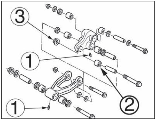
text_image
Technical diagram showing exploded view of mechanical components with numbered parts and assembly detailsNOTES FOR USA/CDN MODEL
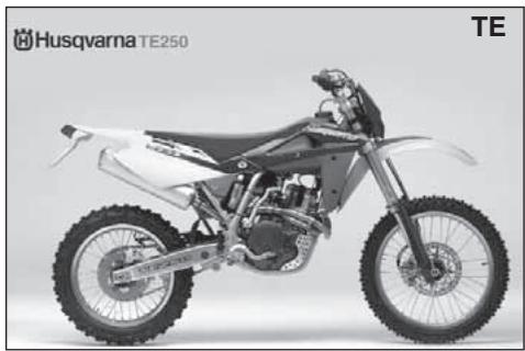
natural_image
Side profile of a white and black Husqvarna TE250 motorcycle with visible dynamics and wheels (no text or symbols on the bike body)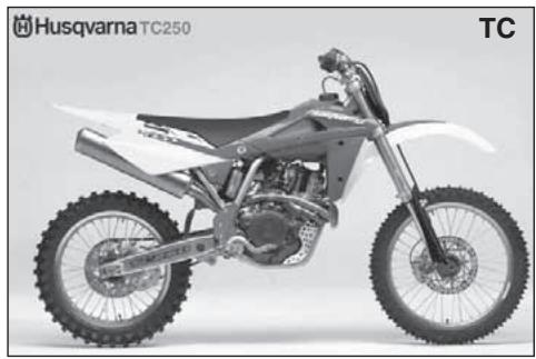
natural_image
Side view of a Masch踏板 (Husqvarna TC250) motorcycle with visible tracks and wheels, no text or symbols on the vehicle itself.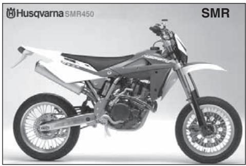
natural_image
Side view of a white and silver semi-motor motorcycle with visible engine and wheels (no text or symbols on the bike body)DISCLAIMER OF WARRANTY
IN ACCEPTING DELIVERY OF THIS MOTORCYCLE THE BUYER OR TRANSFEREE ACKNOWLEDGES THAT HE HAS THOROUGHLY INSPECTED THE MOTORCYCLE, AND FURTHER AGREES TO ACCEPT THE MOTORCYCLE AS IS WITH ALL DEFECTS OR FAULTS, CONCEALED OR OBVIOUS. HE FURTHER AGREES THAT NO WARRANTIES ATTACH, EXPRESS OR IMPLIED, INCLUDING ANY WARRANTY OF MERCHANTABILITY OR FITNESS FOR ANY PARTICULAR PURPOSE. THE BUYER OR TRANSFEREE INDEMNIFIES AND HOLDS HARMLESS CAGIVA U.S.A., MV Agusta Motorcycles S.p.A., THEIR AGENTS AND EMPLOYEES. FOR ANY FAILURE OF PERFORMANCE, COST OF SERVICE, OR REPAIR. THE BUYER FURTHER ACKNOWLEDGES THAT THIS MOTORCYCLE IS NOT INTENDED FOR USE ON PUBLIC STREETS, ROADS, HIGHWAYS, OR TRAILS UNDER PUBLIC JURISDICTION AND THAT USE ON SUCH MAY VIOLATE STATE AND FEDERAL LAW.
Noise emission warranty
MV Agusta Motorcycles S.p.A. warrants that this exhaust system, at the time of sale, meets all applicable U.S. EPA Federal noise standards. This warranty extends to the first person who buys this exhaust system for purposes other than resale, and to all subsequent buyers. Warranty claims should be addressed to Cagiva U.S.A. 2300 MARYLAND ROAD.
WILLOW GROVE, PA 19090-4193
215-830-3300
Tampering warning
Tampering with Noise Control System Prohibited.
Federal law prohibits the following acts or causing thereof:
(1) The removal or rendering inoperative by any person other than for purposes of maintenance, repair, or replacement, of any device or element of design incorporated into any new vehicle for the purpose of noise control prior to its sale or delivery to the ultimate purchaser or while it is in use, and
(2) the use of the vehicle after such device or element of design has been removed or rendered inoperative by any person.
Among those acts presumed to constitute tampering are the acts listed below.
1) Removal of, or puncturing the muffler, baffles, header pipes or any other component which conducts exhaust gases.
2) Removal or puncturing of any part of the intake system.
3) Lack of proper maintenance.
4) Replacing any moving part of the vehicle, or parts of the exhaust or intake system, with parts other than those specified by the manufacturer.
Warning statement
This product should be checked for repair or replacement if the motorcycle noise has increased significantly through use.
Otherwise, the owner may become subject to penalties under state and local ordinances.
SPARK ARRESTER
The TE/SMR models are equipped with a U.S. Forest Service approved spark arrester for maximum efficiency and performance.
"SPARK ARRESTER" MAINTENANCE AND CLEANOUT INSTRUCTIONS
Proceed as follows:
A: First turn counterclockwise fastening rear pin (1) then remove saddle, screws (2) and R.H. side panel (3).
Unhook springs (4) fastening the muffler (5) to the exhaust pipes.
B: Remove the two screws fastening the muffler to the rear frame.
Note*: If silencer or exhaust are difficult to remove, help to slide them apart by tapping gently with a rubber or plastic hammer.
C: remove the six rivets (6) and the endcap (7) from silencer's body;
D: examinate SPARK ARRESTER conditions and remove, if necessary, carbon particles from the SPARK ARRESTER screen;
E: if necessary, inflate air on the SPARK ARRESTER screen, in the opposite direction in respect of the exhausted gas flow;
F: assemble the front endcap on the silencer's body, mounting the screws in the correct position, providing a tight connection between endcap and silencer's body, using, if necessary, a silicone paste;
G: re-assemble the silencer on motorbike, then R. H. side panel and saddle.
Due to the SPARK ARRESTER position on the silencer, if you need only to check the SPARK ARRESTER conditions you can:
A: disassemble the silencer from motorbike;
B: check SPARK ARRESTER conditions simply looking into the silencer from front endcap opening;
C: if the check is positive, you can proceed in re-assembling the silencer on the motorbike;
D: if the check is negative, proceed with the maintenance and cleanout procedure.
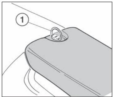
natural_image
Diagram of a mechanical component with a circular arrow labeled '1' pointing to a ring (no text or symbols beyond label)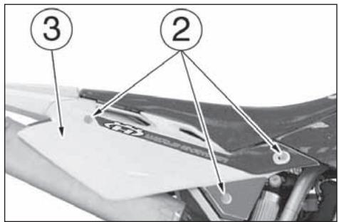
text_image
③ ②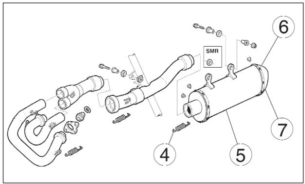
text_image
Technical diagram of a mechanical assembly with numbered components and labeled partsNOTES FOR "AUS" MODEL
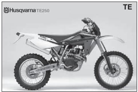
natural_image
Side profile of a white and black Husqvarna TE250 motorcycle with visible dynamics and wheels (no text or symbols on the bike body)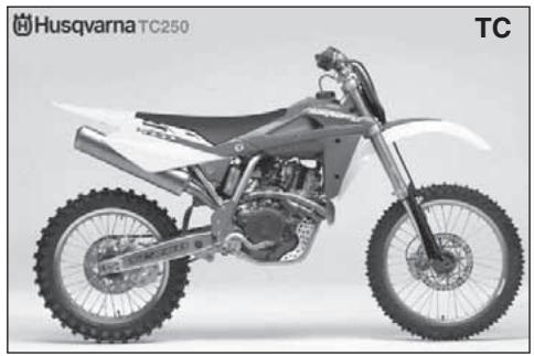
natural_image
Side view of a Mascat 250 motorcycle with visible tracks and wheels (no text or symbols on the bike body)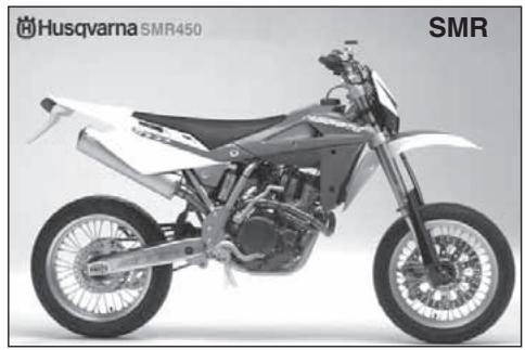
natural_image
Side view of a white and black semi-traw bike with visible engine and wheels (no text or symbols on the bike body)Tampering Warning:
Tampering with Noise Control System Prohibited. Federal law prohibits the following acts or causing therefor:
1) The removal or rendering inoperative by any person other than for purposes of maintenance, repair, or replacement, of any device or element of design incorporated into any new vehicle for the purpose of noise control prior to its sale or delivery to the ultimate purchaser or while it is in use, and
2) the use of the vehicle after such device or element of design has been removed or rendered inoperative by any person.
Among those acts presumed to constitute tampering are the acts listed below.
1) Removal of, or puncturing the muffler, baffles, header pipes or any other component which conducts exhaust gases.
2) Removal or puncturing of any part of the intake system.
3) Lack of proper maintenance.
4) Replacing any moving part of the vehicle, or parts of the exhaust or intake system, with parts other than those specified by the manufacturer.
This product should be checked for repair or replacement if the motorcycle noise has increased significantly through use.
Otherwise, the owner may become subject to penalties under state and local ordinances.
| Description | Operation | Pre-delivery | Description | Operation | Pre-delivery |
| Engine oil | Check level | ☐ | Tyres | Check pressure | ☐ |
| Two-stroke mix oil level | Check level | ☐ * | Side stand | Check operation | ☐ |
| Coolant | Check / Restore level | ☐ | Side stand switch | Check operation | ☐ |
| Cooling system | Check for leakage | ☐ | Electrical equipment | Check operation | ☐ |
| Electric fans | Check operation | ☐ * * | Instrument panel | Check operation | ☐ |
| Spark plugs | Check / Replace | ☐ | Lights / Visual signals | Check operation | ☐ |
| Throttle body / Carburettor | Check and adjust | ☐ | Horn | Check operation | ☐ |
| Brakes / Clutch fluid | Check level | ☐ | Headlight | Check operation | ☐ |
| Brakes / Clutch | Check operation | ☐ | Ignition switch | Check operation | ☐ |
| Brakes / Clutch | Check lines for leakage | ☐ | Locks | Check operation | ☐ |
| Throttle control | Check operation | ☐ | Screws and nuts | Check / Tighten | ☐ |
| Throttle control | Check / Adjust play | ☐ | Hose clamps | Check / Tighten | ☐ |
| Choke control | Check operation | ☐ | General lubrication | ☐ | |
| Flexible controls and transm. | Check / Adjust | ☐ | General test | ☐ | |
| Drive chain | Check / Adjust | ☐ |
※ : only for motorcycles with 2 stroke engine
※※: only for some models

text_image
Image containing a series of vertical black bars on white background, resembling a barcode or pattern.| SMR 400, 450, 510- 2006 - TE 250, 450, 510 - 2006 | WARTUNGSTABELLE (FÜR DIESE KONTROLLEN WENDEN SIE SICH AN IHREN VERTRAGSHÄNDLER HUSQVARNA) ESQUEMA DE MANTENIMIENTO PERIODICO(PARA EFECTUAR ESTAS OPERACIONES DIRÍJASE A SU CONCESIONARIO HUSQVARNA) | ||||
| TEILE- PARTICULAR | COUPON- CUPÓN | COUPON- CUPÓN | COUPON- CUPÓN | ||
| SMR 400, 450, 510- 2006 - TE 250, 450, 510 - 2006- ÜBLICHES MOTORRAD, STRAße GESETZLICH (mit beschränktem MACHT-MOTOR):SMR 400, 450, 510- 2006; TE-TC 250, 450, 510 - 2006- MOTOCICLO DE SERIE, PARA USO VIAL (A POTENCIA LIMITADA):SMR 400, 450, 510- 2006; TE-TC 250, 450, 510 - 2006 | NACH DEN ERSTEN 1000Km- DESPUES LOS PRIMEROS 1000Km | ALLE 5000 KM CADA 5000 KM | ALLE 10000Km CADA 10000Km | WECHSELN WENN NÖTIG- SUBSTITUIR SI NECESARIO | SIEHE SEITE VER PAGINA |
| SMR 400, 450, 510- 2006-MOTOCICLO DA COMPETIZIONE, PER USO AGONISTICO (A PIENA POTENZA)- COMPETITION MOTORCYCLE, RACING USE (with FULL POWER ENGINE)- MOTOCYCLE DE COMPÉTITION, POUR USAGE SPORTIF (AVEC LA PLEINE PUISSANCE) | NACH DEN ERSTEN 3 STUNDEN- DESPUES LAS PRIMERAS 3 HORAS | ALLE 5 STUNDEN CADA 5 HORAS | ALLE 15 STUNDEN CADA 15 HORAS | ||
| TREIBSTOFFROHR- TUBERÍAS CARBURANTE | C | X | # | ||
| GERÁUSCHDÄMPFENDES MATERIAL FÜR AUSPUFF- MATERIAL FONOABSORBENTE SILENCIADOR | X | 196-197, 279 | |||
| AUSPUFFROHR UND SCHALLDÄMPFER- TUBO DE ESCAPE Y SILENCIADOR | C | X | # | ||
| RADSPEICHENSSPANNUNG- TENSION RADIOS RUEDAS | C | C | 224-225 | ||
| RADNABENLAGER- COJÍNETES CUBOS RUEDAS | C | X | # | ||
| KRANZ- CORONA TRASERA | S | # | |||
| SCHRAUBENANZIEHUNG FÜR HINTERKRANZ- TORSION TORNILLOS CORONA TRASERA | C | C | C | 152-153, 158-159 | |
| SEKUNDÄRE ÜBERTRAGUNGSKETTE- CADENA TRANSMISIÓN SECUNDARIA | CL | CL | S | 152-153 | |
| KONTROLLE VERSCHRAUBUNG KALTGESENKBOLZEN- CONTROL GENERAL AJUSTE TUERCAS | C | C | # | ||
LEGENDE- LEYENDA
S: WECHSELN- SUBSTITUCIÓN
C: KONTROLLIEREN- CONTROL
P: REINIGEN- LIMPIEZA
R: REVISION- REVISION
L: SCHMIERUNG-BESCHMEIREN- ENGRESAJE-LUBRICACIÓN
: SIEHE WERKSTATTHANDBUCH- VER MANUAL DE OFICINA
ANMERKUNG- NOTAS
DICHTUNGWECHSE: BEI JEDEM DEMONTAGE- SUBSTITUIR LAS EMPACURAS EN EL CASO DE DESMONTAJE
SCHRAUBEN VERSCHLEISS: WECHSELN- SUBSTITUIR TORNILLOS Y TUERCAS EN EL CASO DE DESGASTE
SCHLAMMIGES UND SANDIGES GELÄNDEN: EIN ALLGEMEINE KONTROLLE DURCHFÜHREN- DESPUÉS DE LA CARRERA SOBRE UN TERRENO FANGOSO O ARENOSO, EFECTUAR UN CONTROL GENERAL
INDICE ALFABETICO
Pagina
A
Accensione 28
Adjusting the carburetor 108
Adjusting the clutch....130
Adjusting the driven transmission 150
Adjusting the fork 138
Adjusting the front brake control lever....124
Adjusting the headlamp 246
Adjusting the idle 108
Adjusting the rear brake idle stroke 128
Adjusting shock absorber hydraulic brake....148
Adjusting shock absorber preload spring....146
Adjusting the rear brake pedal position 126
Adjusting the steering bearing play....120
Adjusting the suspensions according to the track special conditions....134
Adjusting the throttle cable 106
Adjusting the valve play 114
B
Battery 236
Brakes....166
Brake disc cleaning....174
Brake disc warpage 172
Brake disc wear 172
Brake pad assembly 170
Brake pad wear 168
Brake pad disassembly....168
C
Carburettor 30
Carburettor starter 52
Chain lubrication....154
Checks after every competition....268
Checks during running in 96
Check of air filter....118
Check of chain, pinion, crown wear 152
Check of clutch fluid level 130
Check of cooling fluid 104
Check of front brake fluid level 124
Check of engine oil 98
Check of rear brake fluid level....128
Cleaning the air filter 118
Clutch 32
Clutch control 74
INDEX ALPHABETIQUE
Page
A
Control position....22
D Digital instrument ....54
Draining the front brake fluid....172
Draining the rear brake fluid 174
Driven transmission chain....32
E Engine assembling fits ....198
Electric diagram 229, 231, 235
Electric elements ......226
Engine lubrication....42, 44
Engine oil replacement....100,
Engine start 84
Engine stop....90
F Filling the braking system ....182
Fluid change 180
Fork oil level 140
Fuel....50
Fuel cock....46
Front brake control 68
Front braking system bleeding 168
Front fork....36
G Gearbox control ....78
Gearbox outlet pinion 32
General cleaning....272
H Handlebar commutators ....72
Handlebar position change 142
Headlamp bulbs replacement 242
Hydraulic clutch bluding 132
I Ignition 28
Important notice 14
L Long inactivity ....268
E Embrayage ....32
Nettoyage plaquettes ....170
Motorcycle stop....90
Muffler on the exhaust 196
0
Oil filters replacement 100
Overhauling the wheels 222
P
Pad cleaning 170
Parts replacement....14
Pilot lights ....54
Preliminary checks 80
R
Rear brake control 76
Rear crown 32
Rear fork 36
Rear taillight bulb replacement 244
Running in 94
Rear braking system bleeding 192
Removing the front wheel 160
Removing the rear wheel 162
S
Steering lock 70
Side stand....48
Spark-arrester....279
Spark plug....28
Spark plug check 110
Special tools 250
Starting decompressor 86
T
Throttle control 68
Tires 38,164
Tool outfit 248
V
Vehicle identification number 20
Voltage regulator....112
W
Wheel pin bending 224
Wheel spokes 224
Wheels 36
secondaire 150