LBC 36 - Lawn mower Cotech - Free user manual and instructions
Find the device manual for free LBC 36 Cotech in PDF.


| Product Type | Lawn Mower (Electric) |
| Brand | Cotech |
| Model | LBC 36 |
| Power Source | Battery |
| Battery Voltage | 36 V |
| Cutting Width | 36 cm |
| Cutting Height Adjustment | Central lever with 6 positions (25-75 mm) |
| Grass Collection Bag | 40 L soft bag |
| Mulching Function | Yes (requires mulching plug) |
| Weight | 15 kg |
| Dimensions (L x W x H) | 78 x 45 x 45 cm |
| Noise Level (LWA) | 75 dB(A) |
| Vibration Level | 5.0 m/s² |
| Safety Features | Motor brake, dual switch start, safety key |
| Frame Material | Steel deck with durable paint |
| Wheel Size | Front: 150 mm, Rear: 200 mm |
| Recommended Lawn Area | Up to 500 m² |
| Charging Time | Approximately 1.5 hours |
| Running Time | Up to 30 minutes (full charge) |
| Maintenance | Regular blade sharpening, cleaning after use |
| Spare Parts Availability | Blades, battery, bag, filter (contact Cotech support) |
Frequently Asked Questions - LBC 36 Cotech
User questions about LBC 36 Cotech
0 question about this device. Answer the ones you know or ask your own.
Ask a new question about this device
Download the instructions for your Lawn mower in PDF format for free! Find your manual LBC 36 - Cotech and take your electronic device back in hand. On this page are published all the documents necessary for the use of your device. LBC 36 by Cotech.
USER MANUAL LBC 36 Cotech
Brush Cutter/Grass Trimmer
Sly-/grästrimmer
Busk-/gresstrimmer
Read the entire instruction manual carefully and make sure that you fully understand it before you use the equipment. Keep the manual for future reference.
Viktig information:
natural_image
Technical line drawing of a mechanical device with articulated arms and levers (no text or symbols)ART.NO
MODEL
40-8677
LBC 36
Ver. 20130724
Original instructions
Bruksanvisning i original
4-Stroke Brush Cutter/Grass Trimmer
ART.NO 40-8677 MODEL LBC 36
Please read the entire instruction manual before using the product and then save it for future reference. We reserve the right for any errors in text or images and any necessary changes made to technical data. If you have any questions regarding technical problems please contact our Customer Services.
Note: Check the engine oil level before starting the engine, refer to the Care, maintenance and storage - Engine oil, refilling and changing section below.
Safety
Warning: Children, pets and bystanders should keep a distance of at least 15 metres away from the grass trimmer when it is being used. Switch the grass trimmer off immediately if anyone comes closer.
Product safety labels

Wear protective head gear, protective eyewear/visor and ear defenders.

Wear protective gloves.

Wear safety footwear.

Read the instruction manual carefully and make sure that you understand its contents before you use the product. Save the manual for future reference.

Stones and other debris can be ejected by the trimmer.

Do not permit anyone else to come close to the trimmer when it is in use. Children, pets and bystanders should keep a distance of at least 15 metres away from the trimmer when it is being used.

Do not touch the blade whilst it is rotating.
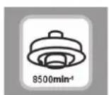
Only accessories approved for speeds up to 8500 rpm should be used.

Warning! Hot surface. Do not touch.
Safety
Note: Switch off the engine before all servicing, adjusting and cleaning of the trimmer.
- Read the entire instruction manual before operating the trimmer until you understand and can follow all the safety instructions and warnings. Make sure that you understand how the trimmer works and know how to use all the controls.
- Never operate the trimmer if you are tired or sick. Do not use the trimmer whilst under the influence of drugs, alcohol or medicine.
- The trimmer is only intended for normal domestic use and only in the manner described in this instruction manual.
- The trimmer must never be used without the debris shield in place and properly fitted.
- Wear suitable attire. Do not wear loose-fitting clothing or jewellery. Keep hair, clothes and gloves away from moving parts. Loose-fitting clothes, jewellery or long hair could become caught in moving parts.
- Wear protective footwear, tight-fitting clothes and safety glasses/visor, ear defenders and a helmet.
- Always be careful when handling fuel. Open the fuel tank carefully and release any pressure which might have built up in the tank. Wipe off any spilt fuel and move the trimmer at least 3 metres away from the refuelling location before starting it.
- Remove all easily ignitable/flammable material from the location in which fuel is handled or stored. Never refuel the trimmer or handle fuel in areas where petrol fumes may reach sparks or naked flames.
- Do not smoke while refuelling or using the trimmer.
- Always hold both handles of the trimmer firmly with your fingers on one side of the handle and thumb on the other side, once the engine is running.
• Always keep the trimmer head/brush cutter blade below waist height during use. - Keep all body parts away from the trimmer head or brush cutter blade when the engine is running.
• Make sure that the trimmer head or cutter blade is not in contact with any object before starting. - Only transport/move the trimmer with the engine switched off.
- Always inspect the trimmer before starting it. Do not start it if there are worn, missing or damaged parts. Never use the brush cutter/grass trimmer if it is damaged, incorrectly adjusted or incorrectly assembled.
- Before operating the trimmer, make sure that all nuts and bolts are tight, that there is no fuel leakage and that all the safety features are intact and correctly fitted.
- Check that the brush cutter blade/trimmer head is intact and correctly fitted before starting.
- Inform anyone who will operate the trimmer that the brush cutter blade could possibly bind in the cut or strike a solid object and stop rotating. This could cause sudden, forceful, uncontrolled kickback. Every operator must be aware of and prepared for this eventuality.
- All service of the trimmer other than that mentioned in this instruction manual should be carried out by qualified personnel and only using original spare parts.
- Switch off the trimmer before laying it on the ground.
• Make sure that the brush cutter blade is sharp and undamaged before using it. - Be extra vigilant when cutting small bushes or thick grass. They can bind around the brush cutter blade.
- Keep the handles clean, dry and free from oil and/or fuel.
- Never start the trimmer indoors. Exhaust fumes are dangerous to inhale. They contain carbon monoxide.
- Avoid running the trimmer head or brush cutter blade near small objects which can be thrown. Clear the working area of all objects which could be thrown before operating the trimmer.
- Always stand below the trimmer if you are using it on a slope. Never use the trimmer on a slope if there is the slightest risk of you losing your footing, falling or sliding. Hold the trimmer firmly with both hands.
- Keep the trimmer free from grass cuttings and other debris, especially the debris shield, the area around the blade/trimmer head and the engine.
• The trimmer must only be used by adults who have read the instruction manual. - Do not use the grass trimmer without the silencer or silencer cover.
• The silencer can become very hot, do not touch it with your hands or other parts of your body. - The trimmer must not be used for any other purpose than for clearing brushwood and trimming grass.
- Discard and replace the trimmer head or brush cutter blade immediately if it is damaged in any way.
- The trimmer must not be modified or used for any purpose other than that for which it is intended. Doing so increases the risk of accidents and is not covered by the guarantee.
- Do not use the trimmer close to flammable gases and liquids since this could cause a fire or lead to an explosion.
- Bear in mind that the trimmer head/brush cutter blade will continue to rotate after the trimmer has been switched off.
- Let the trimmer head/brush cutter blade come to a complete standstill before putting the trimmer down once it has been switched off.
- Fit the blade cover and lash the trimmer securely whenever transporting it in order to prevent fuel leaks, damage to the trimmer or personal injury.
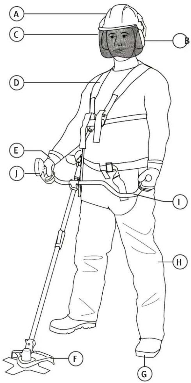
Safety equipment
A. Helmet
B. Ear protectors
C. Visor
D. Harness
E. Gloves
F. Debris shield
G. Safety boots
H. Heavy-duty work trousers
I. Anti-vibration handle
J. Throttle with ignition switch
Parts
Motor
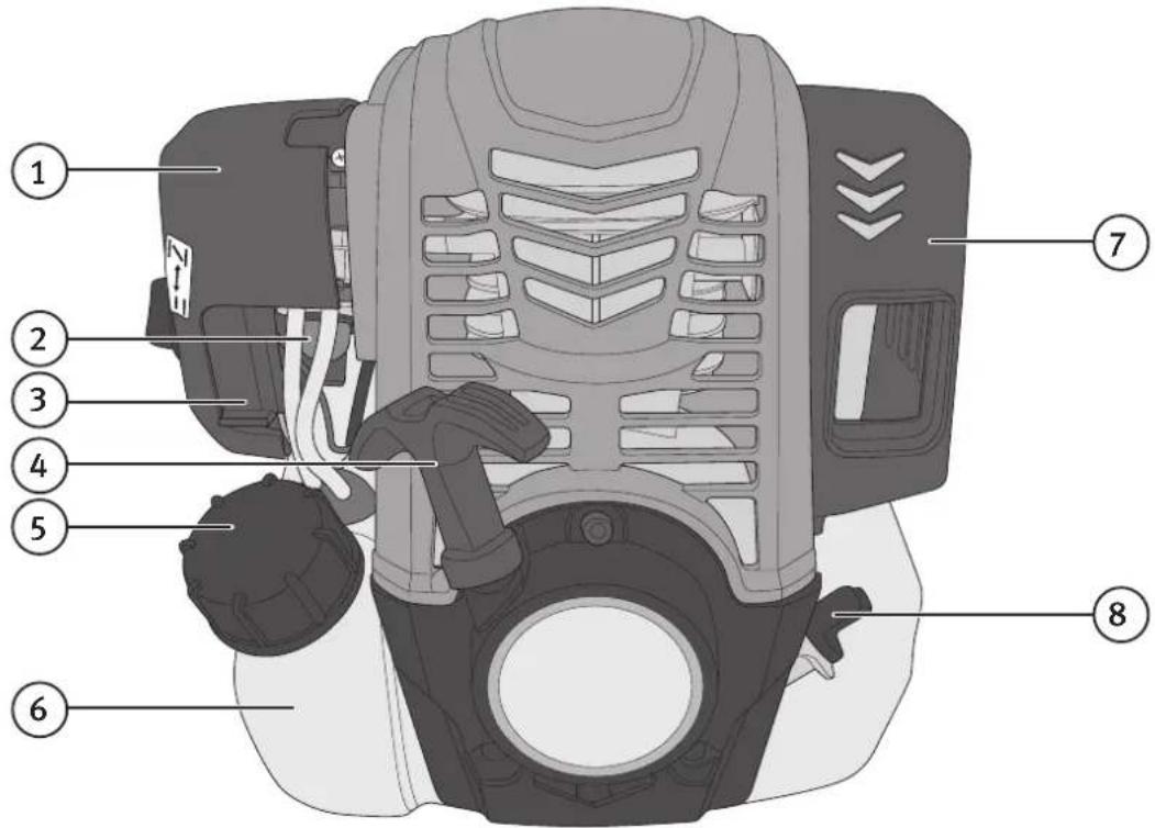
- Air filter
- Priming bulb
- Choke
-
Starter handle
-
Fuel cap
- Fuel tank
- Silencer
- Oil filler cap/dipstick
Bike handle

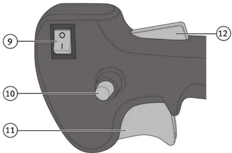
- [On/off] Ignition switch
- Throttle set button (keeps engine on half power)
- Throttle
- Safety switch
Assembly
Attaching the debris shield
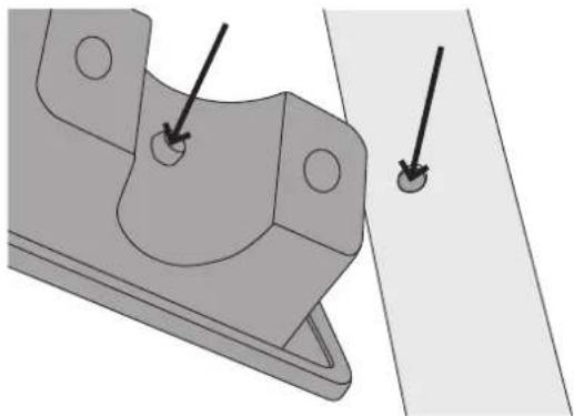
- Remove the two screws and the holder from the debris shield.
natural_image
Mechanical component diagram showing a bracket with mounting holes and two arrows indicating features (no text or symbols present)- Make sure that the peg in the shield bracket slots into the notch in the frame pipe.

natural_image
Mechanical assembly diagram showing a shaft connected to a mechanical component (no text or symbols visible)- Attach the holder and tighten the screws.
Attaching the handle
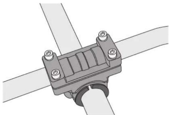
- Open the handle clamp by removing the four screws.

natural_image
Technical illustration of a mechanical assembly with two components, one showing a curved component and the other a flat plate (no text or symbols)- Place the bike handle into the clamp and screw the top of the clamp back on loosely.
natural_image
Mechanical assembly diagram showing a pipe clamp bracket with mounting holes (no text or symbols)- Adjust the angle of the handle before tightening the four screws.
Assembling the frame pipe

natural_image
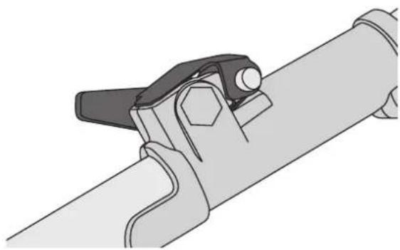
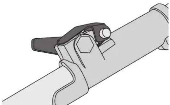
Mechanical diagram of a pipe valve assembly with handle and clamping mechanism (no text or labels)- Undo the clamp on the upper frame pipe to release the locking plate. Insert the lower frame pipe into the clamp so that the hole in the pipe lines up with the slot in the clamp and the release catch.

natural_image
Illustration of hands using a tool to clamp or adjust a pipe fitting (no text or symbols present)-
Press the release catch in and slide the two halves of the frame pipe together.
-
Release the catch and then pull on the pipe to make sure that the catch has located in the hole and fastened the pipe in place.
- Make sure that the lower frame pipe with the trimmer head is at the correct angle to the upper frame pipe with the handle and engine. Push the locking plate down and tighten the locking knob (see fig.).
- To detach the lower frame pipe, undo the locking knob, press in the release catch and pull the pipe out of the clamp.
Fitting the trimmer head

natural_image
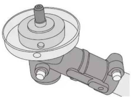
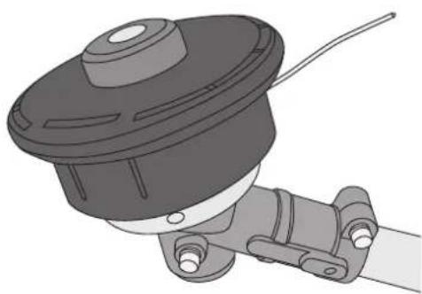
Mechanical component diagram showing a pulley and shaft assembly (no text or symbols)- Fit the inner support washer onto the drive shaft so that the hole lines up with the hole in the side of the housing.
- Lock the drive shaft by poking the larger of the two included Allen keys through all three holes in the cover, housing and the inner support washer.
- Thread the trimmer head onto the drive shaft and screw it finger-tight (see fig.).
Note: The trimmer head has a left-handed thread, so you have to tighten it by turning it the "wrong way".
- Remove the Allen key.
Fitting the brush cutter blade
natural_image
Mechanical component diagram showing a pulley and lever assembly (no text or symbols)- Fit the inner support washer onto the drive shaft.

natural_image
Technical illustration of a mechanical clamp or bracket assembly (no text or symbols)
natural_image
Mechanical assembly diagram showing a wheel and bracket component (no text or symbols)- Fit the cover over the housing so that the holes line up.
natural_image
3D rendering of a mechanical component with a cylindrical housing and attached tubing (no text or symbols visible)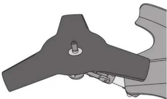
natural_image
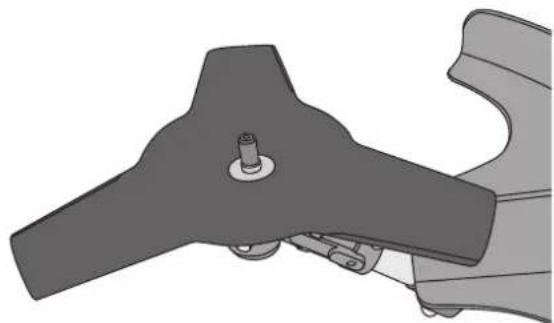
Mechanical component diagram showing a lever and bracket assembly (no text or symbols)- Place the brush cutter blade onto the inner support washer (the text on the blade should be face down, against the washer), make sure the blade is flat against the washer.

natural_image
Mechanical component diagram showing a lever and pivot mechanism (no text or symbols)- Fit the outer support washer, face the concave side of the washer down, against the blade.

natural_image
Mechanical component diagram showing a blade and housing assembly (no text or symbols)-
Fit the cover washer onto the drive shaft.
-
Lock the drive shaft by poking the larger of the two included Allen keys through the holes in the housing and the inner support washer. Screw the nut onto the drive shaft and tighten it well.

natural_image
Mechanical component diagram showing a lever and pivot mechanism (no text or symbols)Operating instructions
Before starting:
Note: Check the engine oil level before starting the engine, refer to the Care, maintenance and storage - Engine oil, refilling and changing section below.
Refuelling
Note:
• Always refuel the trimmer outdoors.
• Petrol is highly flammable.
- Never smoke whilst refuelling the trimmer or handling the fuel.
- Keep the fuel well away from flames and sparks at all times.
• Make sure that the trimmer has been switched off and has cooled down before it is refuelled.
• Use only 95/98 octane petrol.
- Lay the trimmer down in a suitable place for refuelling.
- Remove the fuel cap and fill the tank with petrol.
- Screw the fuel cap back on and wipe up any spills immediately.
- Move the trimmer at least 3 metres away from the refuelling site before starting it.
Starting the engine
Note: Before starting the trimmer, make sure that you have read the entire instruction manual and understood all the safety instructions and warnings. Make sure that you understand how the trimmer works and know how to use all the controls.
Running in the engine
A new engine should be “run in” by using it at low speed and with low resistance for the first few hours. This will help all the moving parts of the engine to loosen up and mate together better and will ultimately lengthen the useful life of the engine. After it has been run in, the engine will provide maximum performance and can be operated at full load. However, the engine should only be operated at full throttle for short periods.
Cold engine
natural_image
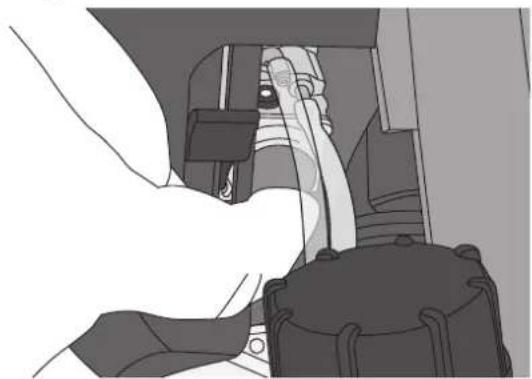
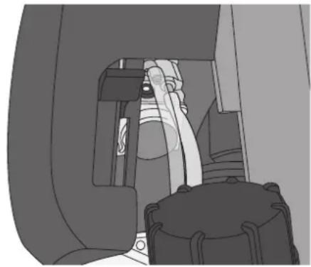
Illustration of a person adjusting a car seatbelt, no text or symbols visible- Press the priming bulb repeatedly until fuel runs back down the clear return tube.

natural_image
Interior view of a vehicle showing a passenger seat, dashboard, and engine compartment (no visible text or symbols)-
Move the choke lever to the closed position (upwards).
-
Set the ignition switch to ON (I).
- Lay the trimmer on the ground so that it is supported by the fuel tank and debris shield. Make sure that the trimmer head or brush cutter blade is clear of the ground and will not contact anything when the trimmer is switched on. Note: Never start the trimmer when it is hanging by the harness or if you are holding it in such a way that you might lose control of the trimmer when it is started.
- With your left hand, grip the trimmer just in front of the engine.
- Gently pull the starter handle until you feel some resistance. Once resistance has been met, finish by pulling the starting handle with a quick and powerful motion.
- Gradually lower the choke lever as the engine warms up. Let the engine warm up for a few minutes after it has been started from cold.
- When the engine has warmed up sufficiently that it idles smoothly, it is ready for use.
Note: The trimmer head/brush cutter blade should not rotate when the engine is idling. If the trimmer head/brush cutter blade rotates with the engine idling, the idling speed needs adjusting, refer to the Care, maintenance and storage - Idle speed adjustment section below.
Warm engine
- Check that the choke is completely open.
- Set the ignition switch to ON (I).
- Lay the trimmer on the ground so that it is supported by the fuel tank and debris shield. Make sure that the trimmer head or brush cutter blade are clear of the ground and will not contact anything when the trimmer is switched on. Note: Never start the trimmer when it is hanging by the harness or if you are holding it in such a way that you might lose control of the trimmer when it is started.
- With your left hand, grip the trimmer just in front of the engine.
- Gently pull the starter handle until you feel some resistance. Once resistance has been met, finish by pulling the starting handle with a quick and powerful motion.
Stopping the engine
- Release the throttle so that the engine is just idling.
- Set the ignition switch to OFF (0).
- Let the trimmer head/brush cutter blade come to a complete stop before laying the trimmer on the ground.
Trimmer operation
The harness
Use the harness as follows:
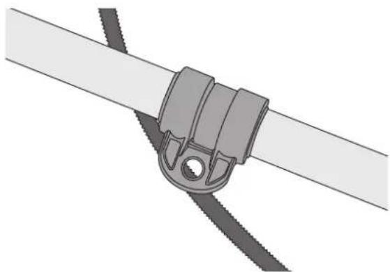
- Put the harness on so that the trimmer hanging clip is on the right-hand side and the quick release tab is on your chest.
natural_image
Mechanical clamp assembly with two parallel rods and a central mounting bracket (no text or symbols)- Hold the trimmer on your right-hand side and hook it onto the harness.
- Adjust the harness so that the trimmer is balanced. Adjust the position and angle of the handle if necessary.
- When using the grass trimmer, the harness should be adjusted so that the trimmer head hangs 0–300 mm off the ground.
- When using the brush cutter, the harness should be adjusted so that the trimmer head hangs 100–300 mm off the ground.
Note: Use no other accessories than the included trimmer head and brush cutter blade. When these cutting attachments wear out, they should only be replaced with identical original spare parts.
- Ensure that you have the appropriate cutting attachment (trimmer head or brush cutter blade) fitted for the task at hand.
- With the engine switched off, put the harness on and hook the trimmer onto it. Adjust the harness so that the trimmer head/brush cutter blade is the correct height off the ground (see above).
- Unhook the trimmer from the harness, lay it on the ground and start the engine.
- When the engine is idling smoothly, hook the trimmer onto the harness.
- Hold the trimmer with both hands.
- Depress the safety switch (12) and the throttle and let the engine speed up.
-
Keep the trimmer head parallel to the ground and swing the trimmer back and forth in a level arc.
-
Bear in mind that it is the tip of the trimmer line which cuts the grass. Do not force the trimmer through thick grass; let the trimmer work at its own pace.
• Take care when using the brush cutter blade not to try and cut through objects which are too coarse for the blade to handle. - Hold the throttle all the way in (full power) whenever using the trimmer.
- Keep a firm footing and balance at all times.
• Do not overreach. - Keep the cutting attachment below waist height.
- Keep all parts of your body away from the rotating parts.
- Adapt your working pattern to the prevalent conditions, do not move the grass trimmer too quickly and work at your own pace.
- Be careful, so the trimmer line doesn't cut the bark of trees or plants that you want to keep.
• Trimming against hard surfaces such as fences, walls and rocks will wear out the trimmer line sooner.
Important considerations when using the brush cutter blade
Use only the supplied brush cutter blade or an identical replacement. A saw-toothed clearing saw blade must not be used.
The brush cutter blade can be tilted to various angles for cutting brush from around tree trunks.
- Normal use: Set the blade to position "A" for normal use when cutting brush.
- Position "B" can also be used if the handles are held firmly.
Note: Never use the blade in position "C". This position can throw small objects up towards any people or animals close by.

Feeding out the trimmer line
- Let the engine come up to full power.
- Tap the trimmer head on the ground and lift it up again.
- The line will be fed out automatically.
- The line will be cut to the correct length by the cut-off knife under the debris shield.
Care, maintenance and storage
Note:
- Switch the trimmer off and let it cool down. Disconnect the spark plug cable from the spark plug (refer to the Changing/servicing the spark plug section below) before cleaning or servicing the trimmer.
- Clean the trimmer using a lightly moistened cloth. Only use mild cleaning agents, never solvents or corrosive chemicals.
- Clean the cooling fins and the ventilation openings in the plastic housing regularly, so the engine is properly cooled.
Filling/changing the engine oil
Remove the oil filler cap (8) and pour in 100 ml oil. Use only SAE 10W-30, API SG.
- The oil level should come up to the edge of the filler hole when the trimmer is lying on the ground supported by the fuel tank and the debris shield.
- Note: Change the oil after the first 20 hours operation and then at the beginning or end of every working season.

Changing the trimmer line

natural_image
Illustration of a hand holding a mechanical component, possibly a tool or clamp, with no visible text or symbols.- Press in the two spring catches on the sides of the trimmer head and remove the cover.

natural_image
3D technical illustration of a mechanical component with internal slots and a coiled cable (no text or symbols)-
Lift up the ends of any remaining line and guide them into the notches on the spool.
-
Pull the spool out of the cover.
- Remove any remaining line from the spool.

natural_image
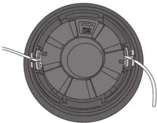
Diagram of a coiled wire coil or solenoid with a central core and multiple coils (no text or symbols)- Begin by hooking the middle of the new line into the notch in the centre of the spool. Make sure that the middle of the new line is notched in.

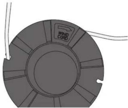
- Wind the new line around the spool in the direction marked on the spool and guide the ends of the line into the notches on the edge of the spool.
natural_image
Top-down technical illustration of a circular mechanical component with internal blades and labeled ports (no text or symbols beyond labels)- Fit the spool back into the cover and guide the ends of the line through the slots in the side of the cover.
natural_image
3D CAD model of a mechanical component with internal cavities and mounting brackets (no text or symbols)
natural_image
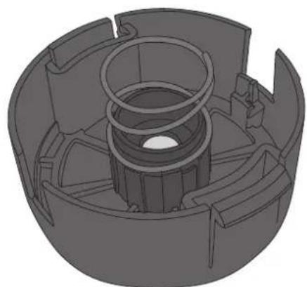
Mechanical component diagram showing a cable inserted into a housing (no text or symbols visible)- Make sure that the spring is seated in the centre of the trimmer head and fit the cover back on. Ensure that the two spring catches lock the cover on securely.
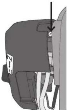
Idle speed adjustment
Any adjustment of the idle speed should be carried out when the engine is warm.
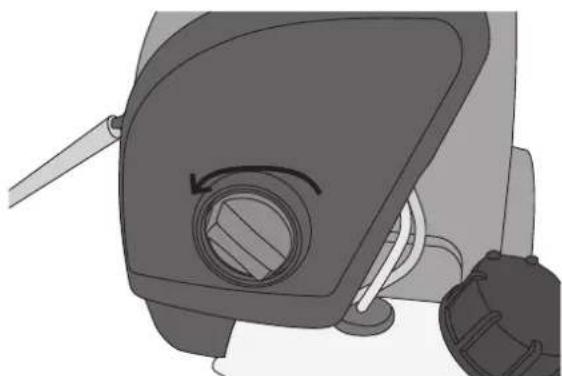
Carefully turn the idle speed adjustment screw as follows:
• Clockwise: Higher idle speed.
• Anticlockwise: Lower idle speed.
natural_image
Mechanical component diagram showing a valve or connector with a downward arrow indicating direction (no text or symbols present)Air filter
natural_image
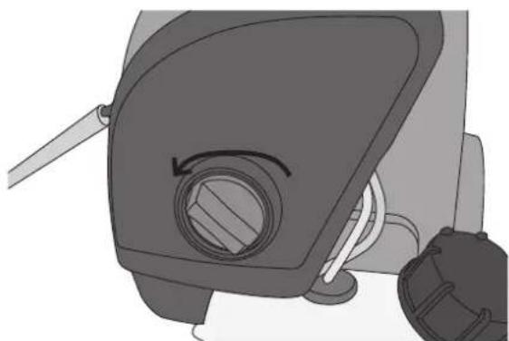
Illustration of a mechanical device with a circular component and attached lever (no text or symbols)- Remove the plastic cover over the air filter and carburettor.

natural_image
Diagram of a mechanical device with a handle and valve, showing internal components (no text or symbols)- Remove the air filter and wash it in mild soapy water.
- Allow the filter to completely dry before refitting it.
Lubrication of the head angle adjuster
The head angle adjuster should be lubricated after every 25 hours of operation.
- Loosen the head of the bolt on the side of the gearbox and smear the pivot with some high temperature grease.
- Wipe off any excess grease.
- Tighten the bolt.

natural_image
Mechanical assembly diagram showing a linkage mechanism with no visible text or symbolsChanging/servicing the spark plug
Note: Only use a spark plug identical to the one which is factory fitted (NGK CMR7H) or equivalent.

natural_image
Mechanical component diagram showing two circular features with arrows pointing to them (no text or symbols present)- Remove the two bolts at the bottom of the plastic cover over the silencer.

natural_image
Illustration of a vacuum cleaner with attached circuit board (no text or symbols)- Press in the top of the cover to release the spring catch and remove the cover.

natural_image
Mechanical component diagram showing a circular opening with an arrow pointing to it (no text or symbols present)- Undo the bolt in the plastic cover over the engine and remove the cover.

natural_image
Technical illustration of a vehicle's internal components, showing engine, chassis, and dashboard assembly (no text or labels)- Disconnect the spark plug cable from the spark plug and remove the spark plug.
Fit a new spark plug and tighten to a torque of 9.8–11.8 Nm (1.0–1.2 kgm).
Checking the spark plug gap
Special tools for measuring and adjusting the gap between the electrodes of spark plugs can be purchased.
If necessary, correct the gap as shown in the figure below.
0.60–0.70 mm

natural_image
Technical line drawing of a spark plug assembly (no text or symbols)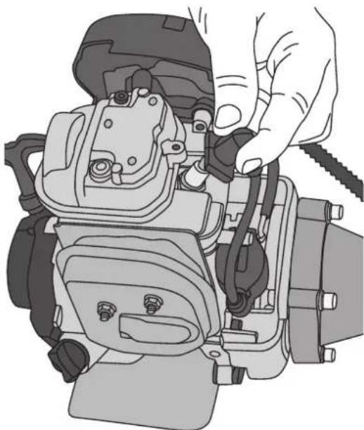
natural_image
Illustration of a hand adjusting or adjusting a mechanical component with wires (no text or symbols visible)Carburettor settings
The carburettor has been factory adjusted for optimum power.
Storage
- The fuel tank and carburettor should not be left filled with petrol over the winter, as this could lead to starting problems.
• Empty the fuel tank by starting the engine and letting it run until it is out of fuel. - Clean the trimmer before putting it away for storage.
• Fit the blade guard onto the brush cutter blade. - Store the trimmer in a dry, dust-free environment out of the reach of children.
Troubleshooting guide
| Problem Cause | |
| The engine won’t start or only runs at low speed. | Incorrect starting procedure. Read the instruction manual.Faulty spark plug. Clean or change the spark plug.Dirt in the carburettor. Get a qualified technician to clean the carburettor.Clogged fuel filter. Change the fuel filter (inside the fuel tank). |
| The engine starts but with loss of power. | Wrong choke setting. Open the choke.Dirty air filter. Clean or change the air filter.Dirt in the carburettor. Get a qualified technician to clean the carburettor. |
| The engine doesn’t respond to the throttle. | Engine not adequately warmed up. Allow the engine to idle for a minute. |
| Loss of power under load. | Faulty spark plug. Clean or change the spark plug. |
| The engine runs irregularly. | Dirt in the carburettor. Get a qualified technician to clean the carburettor. |
Disposal
This product should be disposed of in accordance with local regulations. If you are unsure how to proceed, contact your local authority.
Specifications
Brush cutter blade 255 mm
Trimmer line 2.4 mm
Engine capacity 35.8 cc
Power 1.0 kW (1.36 hp)
Weight 8.4 kg
Fuel tank capacity 0.65 l
Engine oil capacity 0.1 l
Engine speed 9300 rpm
Noise level
$$ \mathrm{LwA}, \mathrm{d} = 1 1 3 \mathrm{dB(A)}, \mathrm{K} = 1. 9 5 \mathrm{dB(A)} $$
Vibration level with brush cutter blade at idle speed: left handle 1,619 m/s ^2 , right handle 1,440 m/s ^2 .
Vibration level with brush cutter blade at full throttle: left handle 5,190 m/s ^2 , right handle 3,043 m/s ^2 .
Vibration level with trimmer head at idle speed: left handle 1,639 m/s ^2 , right handle 1,432 m/s ^2 .
Vibration level with trimmer head at full throttle: left handle 6,187 m/s ^2 , right handle 5,696 m/s ^2 .
Uncertainty: K = 1,5 m/s ^4
natural_image
Mechanical component diagram showing a bracket with mounting holes and two arrows indicating features (no text or symbols present)natural_image
Mechanical assembly diagram showing a shaft and mounting bracket assembly (no text or symbols)natural_image
Technical illustration of a mechanical clamp or bracket assembly with two components (no text or symbols)natural_image
Mechanical assembly diagram showing a bracketed clamp or mounting bracket mounted on a pipe (no text or symbols visible)natural_image
Mechanical diagram of a valve assembly with handle and clamping mechanism (no text or labels)natural_image
Illustration of a hand using a clamp to adjust or install a pipe fitting (no text or symbols present)natural_image
Technical illustration of a mechanical pulley and lever assembly (no text or symbols)natural_image
Mechanical component diagram showing a pulley and lever assembly (no text or symbols)natural_image
Technical illustration of a mechanical clamp or bracket assembly (no text or symbols)
natural_image
Mechanical assembly diagram showing a wheel and lever mechanism (no text or symbols)natural_image
Mechanical component diagram showing a motor or actuator assembly with no visible text or symbols
natural_image
Mechanical component diagram showing a lever and pivot mechanism (no text or symbols)natural_image
Mechanical component diagram showing a lever and mounting bracket assembly (no text or symbols)natural_image
Mechanical component diagram showing a lever and pivot mechanism (no text or symbols)natural_image
Mechanical component diagram showing a lever and pivot mechanism (no text or symbols)Användning
Före start
natural_image
Illustration of a person adjusting a vehicle seatbelt (no text or symbols visible)natural_image
Interior view of a vehicle's seatbelt mechanism (no text or symbols visible)natural_image
Mechanical clamp assembly with two parallel rods and a central mounting bracket (no text or symbols)natural_image
Illustration of a hand holding a mechanical component, possibly a tool or clamp, with no visible text or symbols.natural_image
3D technical illustration of a mechanical component with internal gear-like structure and connecting wires (no text or symbols)natural_image
Diagram of a coiled electrical component with wires, no text or symbols presentnatural_image
Top-down technical illustration of a circular mechanical component with internal blades and a labeled 'FIND CORD' (no text or symbols beyond label)natural_image
3D CAD rendering of a mechanical component with internal cavities and mounting brackets (no text or symbols)
natural_image
Mechanical component with a wire inserted into a housing (no visible text or symbols)natural_image
Mechanical component diagram showing a valve or connector with a downward arrow indicating direction (no text or symbols present)Luftfilter

natural_image
Illustration of a mechanical device with a circular component and attached parts (no text or symbols visible)natural_image
Diagram of a vehicle fuel pump assembly showing internal components and valve (no text or labels)natural_image
Mechanical assembly diagram showing a linkage mechanism with no visible text or symbolsnatural_image
Mechanical component diagram showing two circular features with arrows pointing to them (no text or symbols present)natural_image
Technical line drawing of a mechanical device with no visible text or symbolsnatural_image
Mechanical component diagram showing a circular opening with an arrow pointing to it (no text or symbols present)natural_image
Technical illustration of a vehicle's internal components, showing engine, chassis, and dashboard assembly (no text or labels)natural_image
Technical line drawing of a spark plug assembly (no text or labels)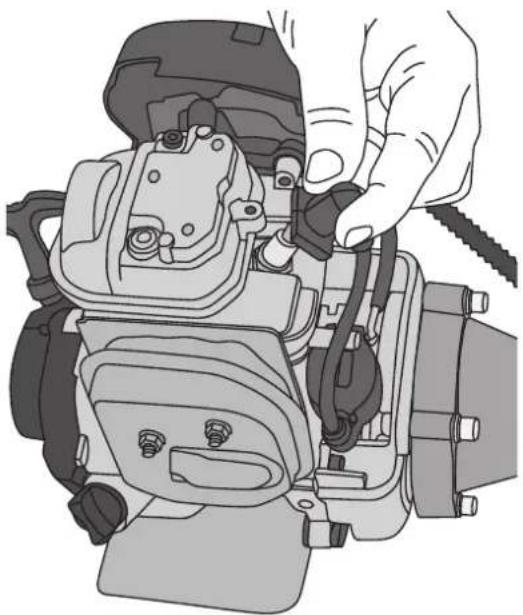
natural_image
Illustration of a hand adjusting or adjusting a mechanical component (no text or symbols visible)Förgasarinställning
- Luftfilter
- Bensinpumpe
- Sjåk
-
Håndtak til startsnøre
-
Tanklokk
- Drivstofftank
- Lyddemper
- Lokk til oljetank
Manøvreringshåndtak
natural_image
Mechanical component diagram showing a bracket with mounting holes and two arrows indicating features (no text or symbols present)- Se til at piggen på beskyttelsesdekselets feste entrer styrehullet i riggrøret.

natural_image
Mechanical assembly diagram showing a shaft connected to a mechanical component (no text or symbols visible)natural_image
Technical illustration of a mechanical clamp or bracket assembly with no visible text or symbolsnatural_image
Mechanical assembly diagram showing a pipe clamp bracket with mounting holes (no text or symbols)natural_image
Mechanical diagram of a valve assembly with handle and clamping mechanism (no text or labels)natural_image
Illustration of a hand using a clamp to adjust or install a pipe fitting (no text or symbols visible)-
Trykk sperren ned og skyv riggrøret sammen.
-
Slipp opp sperren og kontroller at sperren festes i hullet på riggrøret.
- Kontroller at det nederste riggrøret ved trimhodet er i riktig vinkel mot det øvre røret med håndtaket og motoren. Trykk låsebraketten ned og lås med låserattet (se bilde).
- Demontering av riggrøret skjer ved at skru opp låserattet. Trykk deretter ned sperren og trekk riggrøret ut.
natural_image
Technical illustration of a mechanical clamp or bracket assembly (no text or symbols)natural_image
Mechanical component diagram showing a pulley and lever assembly (no text or symbols)natural_image
Mechanical assembly diagram showing a wheel and linkage mechanism (no text or symbols)natural_image
3D rendering of a mechanical component with no visible text or symbolsMontering av klinge

natural_image
Mechanical component diagram showing a pulley and mounting bracket assembly (no text or symbols)- Monter den innvendige støtteskiven.
natural_image
Mechanical component diagram showing a bracket and mounting base assembly (no text or symbols)- Plasser klingen på den innvendige skiven med klingens tekst vendt mot støtteskiven. Pass på at klingen sentreres på skiven.

natural_image
Mechanical component diagram showing a lever and base assembly (no text or symbols)- Monter den ytre skiven. Vend skivens forsenkede side mot klingen.

natural_image
Mechanical component diagram showing a three-blade fan assembly with a central hub and mounting bracket (no text or symbols)natural_image
Mechanical component diagram showing a pin and lever assembly (no text or symbols)Bruk
Før start
natural_image
Illustration of a person's seatbelt being adjusted for a vehicle (no text or symbols visible)- Trykk på bensinpumpen flere ganger til bensinen renner tilbake til den transparente returslangen.
natural_image
Interior view of a vehicle's seatbelt mechanism (no text or symbols visible)natural_image
Mechanical clamp assembly with a cylindrical component attached to a straight rod (no text or symbols visible)natural_image
Illustration of a hand holding a mechanical component, possibly a tool or clamp, with no visible text or symbols.natural_image
3D technical illustration of a mechanical component with internal gear-like structure and two curved wires (no text or symbols)natural_image
Diagram of a coiled electrical component with wires, no text or symbols present- Start med å feste den nye tråden i uttaket som sitter midt på spolen. Pass på at du er i midten på den nye tråden.
natural_image
Top-down technical diagram of a circular mechanical component with internal blades and a labeled wind cord (no text or symbols beyond the label)natural_image
3D CAD rendering of a mechanical component with internal cavities and mounting brackets (no text or symbols)
natural_image
Mechanical component diagram showing a cable inserted into a housing (no text or symbols visible)natural_image
Mechanical component diagram showing a valve or connector with wires and a label 'Z' (no readable text or symbols)Luftfilter

natural_image
Mechanical device with circular component and mechanical joints (no visible text or symbols)
natural_image
Diagram of a mechanical device with a handle and valve, showing internal components (no text or symbols)natural_image
Mechanical assembly diagram showing a linkage mechanism with no visible text or symbolsTennplugg-skifte/-service
Obs! Bruk kun tennplugg som er identisk med den som sitter på ved levering (NGK CMR7H eller liknende).

natural_image
Mechanical component diagram showing a valve or connector with two directional arrows indicating flow or movement (no text or symbols present)- Skru ut de to skruene i underkant av plastdekselet over lyddemperen.

natural_image
Illustration of a mechanical device with no visible text or symbolsnatural_image
Mechanical component diagram showing a circular opening with a white arrow pointing to it, no text or symbols presentnatural_image
Technical illustration of a vehicle's internal components, showing engine, air intake, and exhaust system (no text or labels)natural_image
Technical line drawing of a spark plug assembly (no text or labels)
natural_image
Illustration of a hand adjusting or adjusting a mechanical component with no visible text or symbolsnatural_image
Mechanical component diagram showing a bracket with two circular holes and two downward arrows indicating features (no text or symbols present)natural_image
Mechanical assembly diagram showing a shaft and mounting bracket assembly (no text or symbols)natural_image
Technical illustration of a mechanical assembly with a bracket and a slot (no text or symbols)natural_image
Mechanical assembly diagram showing a clamp bracket mounted on a pipe with two screws (no text or symbols)natural_image
Mechanical diagram of a valve assembly with handle and clamping mechanism (no text or labels)natural_image
Illustration of hands using a tool to clamp or adjust a pipe fitting (no text or symbols visible)natural_image
Mechanical component diagram showing a pulley and mounting bracket assembly (no text or symbols)natural_image
Technical illustration of a mechanical pulley and lever assembly (no text or symbols)- Asenna sisempi tukilevy.
natural_image
Technical illustration of a mechanical clamp or bracket assembly (no text or symbols)
natural_image
Mechanical component diagram showing a wheel and mounting bracket assembly (no text or symbols)natural_image
Mechanical component diagram showing a motor or actuator assembly with no visible text or symbols
natural_image
Mechanical component diagram showing a bracket and mounting bracket assembly (no text or symbols)natural_image
Mechanical component diagram showing a lever and base assembly (no text or symbols)natural_image
Mechanical component diagram showing a blade and housing assembly (no text or symbols)natural_image
Mechanical component diagram showing a lever and pivot mechanism (no text or symbols)Käyttö
Ennen käynnistystä
natural_image
Illustration of a person's seatbelt being adjusted for a car (no text or symbols visible)natural_image
Interior view of a vehicle's seatbelt mechanism (no text or symbols visible)natural_image
Mechanical clamp assembly with two parallel rods and a central mounting bracket (no text or symbols)natural_image
Illustration of a hand holding a mechanical component, possibly a tool or clamp, with no visible text or symbols.natural_image
3D technical illustration of a mechanical component with internal gear-like structure and connecting wires (no text or symbols)natural_image
Diagram of a coiled electrical component with wires, no text or symbols presentnatural_image
Top-down technical illustration of a circular mechanical component with internal blades and a central hub, no text or symbols present.natural_image
3D CAD model of a mechanical component with internal cavities and mounting brackets (no text or symbols)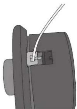
natural_image
Mechanical component diagram showing a cable inserted into a housing (no text or symbols visible)natural_image
Mechanical component diagram showing a valve or connector with wires and a label (no readable text or symbols)Ilmansuodatin
natural_image
Illustration of a mechanical device with a circular component and attached parts (no text or symbols)natural_image
Diagram of a mechanical device with a handle and valve, showing internal components (no text or symbols)natural_image
Mechanical assembly diagram showing a linkage mechanism with no visible text or symbolsSytytystulpan vaihto/huolto
natural_image
Mechanical component diagram showing a bracket with two arrows pointing to specific parts (no text or symbols present)natural_image
Illustration of a mechanical device with no visible text or symbolsnatural_image
Mechanical component diagram showing a cylindrical part with a highlighted hole and a tool inserted (no text or symbols)natural_image
Technical illustration of a vehicle's internal components, showing engine, chassis, and dashboard assembly (no text or labels)natural_image
Technical line drawing of a spark plug assembly (no text or symbols)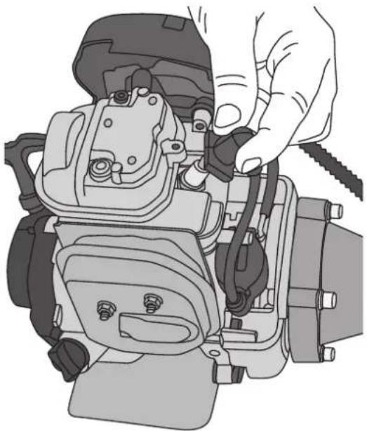
natural_image
Illustration of a hand adjusting or adjusting a mechanical component with no visible text or symbolsKaasutinasetukset
natural_image
Mechanical component diagram showing a bracket with mounting holes and two arrows indicating features (no text or symbols present)natural_image
Mechanical assembly diagram showing a shaft connected to a mechanical component (no text or symbols visible)natural_image
Technical illustration of a mechanical assembly with two views of a bracket (no text or symbols)natural_image
Mechanical assembly diagram showing a pipe clamp bracket with mounting holes (no text or symbols)natural_image
Mechanical diagram of a pipe clamp or valve assembly (no text or symbols visible)natural_image
Illustration of a hand using a clamp to adjust or install a pipe fitting (no text or symbols visible)natural_image
Technical illustration of a mechanical component with pulley and mounting base (no text or symbols)natural_image
Mechanical component diagram showing a pulley and lever assembly (no text or symbols)natural_image
Technical illustration of a mechanical clamp or fitting component (no text or symbols)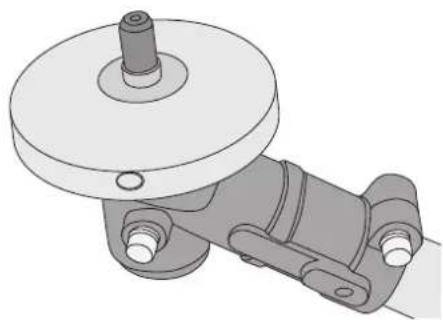
natural_image
Mechanical assembly diagram showing a wheel and bracket component (no text or symbols)natural_image
Illustration of a mechanical component with a circular top and attached pipe (no text or symbols)
natural_image
Mechanical component diagram showing a lever and pivot mechanism (no text or symbols)natural_image
Mechanical component diagram showing a lever and base assembly (no text or symbols)natural_image
Mechanical component diagram showing a blade and housing assembly (no text or symbols)natural_image
Mechanical component diagram showing a lever and bracket assembly (no text or symbols)Bedienung
Vor dem Einschalten
natural_image
Illustration of a person's seatbelt being adjusted for a car (no text or symbols visible)natural_image
Mechanical assembly diagram showing a belt drive mechanism (no text or symbols visible)natural_image
Mechanical clamp assembly with a cylindrical component attached to a straight rod (no text or symbols visible)natural_image
Illustration of a hand holding a mechanical component, possibly a tool or clamp, with no visible text or symbols.natural_image
3D technical illustration of a mechanical component with internal blades and a coiled cable (no text or symbols)natural_image
Diagram of a coiled wire coil wrapped in a black housing, with no text or symbols present.natural_image
Top-down technical illustration of a circular mechanical component with wind cord and coiled cable (no text or symbols)natural_image
3D CAD model of a mechanical component with internal cavities and mounting brackets (no text or symbols)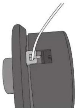
natural_image
Mechanical component with a wire inserted into a housing (no visible text or symbols)natural_image
Mechanical component diagram showing a cable or wire connection with a downward arrow indicating direction (no text or symbols present)Luftfilter

natural_image
Illustration of a mechanical device with a circular component and attached parts (no text or symbols visible)natural_image
Mechanical component diagram showing a valve assembly with a knob and handle (no text or symbols)natural_image
Mechanical assembly diagram showing a linkage mechanism with no visible text or symbolsnatural_image
Mechanical component diagram showing two circular features with arrows pointing to them (no text or symbols present)natural_image
Technical line drawing of a mechanical device with no visible text or symbolsnatural_image
Technical illustration of a mechanical component with a highlighted circular feature and an arrow indicating direction (no text or symbols present)natural_image
Technical illustration of a vehicle's internal components, showing engine, air intake manifold, and exhaust valve (no text or labels)natural_image
Technical line drawing of a spark plug assembly (no text or labels)
natural_image
Illustration of a hand adjusting or adjusting a mechanical component with wires and parts (no text or symbols visible)Declaration of Conformity
Machinery directive 2006/42/EC
EN ISO 11806-1:2011
VCA HEADQUARTERS, THE EASTGATE OFFICE CENTRE, EASTGATE ROAD, BRISTOL BS5 6XX, UNITED KINGDOM HAS CARRIED OUT THE TYPE APPROVAL. TYPE-APPROVAL NUMBER: e11*97/68SA*2010/26*1650*00

Klas Balkow President
Insjön, Sweden, 2013-02-21
SVERIGE
KUNDTJÄNST
Tel:
0247/445 00
Fax:
0247/445 09
E-post: kundservice@clasohlson.se
INTERNET
www.clasohlson.se
BREV Clas Ohlson AB, 793 85 INSJÖN
NORGE
KUNDESENTER
Tlf.:
23 21 40 00
Faks:
23 21 40 80
E-post: kundesenter@clasohlson.no
INTERNETT
www.clasohlson.no
POST
Clas Ohlson AS, Postboks 485 Sentrum, 0105 OSLO
SUOMI
ASIAKASPALVELU
Puh.: 020 111 2222
10 – 13 Market Place
Kingston Upon Thames
Surrey
KT1 1|Z
DEUTSCHLAND
KUNDENSERVICE


- Brush Cutter/Grass Trimmer
- 4-Stroke Brush Cutter/Grass Trimmer
- Safety
- Product safety labels
- Safety equipment
- Parts
- Motor
- Bike handle
- Assembly
- Attaching the debris shield
- Attaching the handle
- Assembling the frame pipe
- Fitting the trimmer head
- Fitting the brush cutter blade
- Operating instructions
- Before starting:
- Refuelling
- Note:
- Starting the engine
- Running in the engine
- Cold engine
- Warm engine
- Stopping the engine
- Trimmer operation
- The harness
- Important considerations when using the brush cutter blade
- Feeding out the trimmer line
- Care, maintenance and storage
- Filling/changing the engine oil
- Changing the trimmer line
- Idle speed adjustment
- Air filter
- Lubrication of the head angle adjuster
- Changing/servicing the spark plug
- Checking the spark plug gap
- Carburettor settings
- Storage
- Disposal
- Specifications
- Användning
- Före start
- Luftfilter
- Förgasarinställning
- Manøvreringshåndtak
- Montering av klinge
- Bruk
- Før start
- Tennplugg-skifte/-service
- Käyttö
- Ennen käynnistystä
- Ilmansuodatin
- Sytytystulpan vaihto/huolto
- Kaasutinasetukset
- Bedienung
- Vor dem Einschalten
- Declaration of Conformity
- SVERIGE
- NORGE
- SUOMI
- DEUTSCHLAND
Brand : Cotech
Model : LBC 36
Category : Lawn mower