USER MANUAL EBC 1040 RYOBI
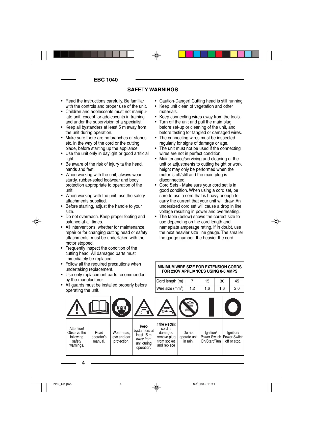
| MINIMUM WIRE SIZE FOR EXTENSION CORDS
FOR 230V APPLIANCES USING 0-6 AMPS |
| Cord length (m) | 7 | 15 | 30 | 45 |
| Wire size (mm²) | 1,2 | 1,6 | 1,6 | 2,0 |
| ! | ! | ! | ! | ! | ! | ! | |
| Attention!
Observe the
following
safety
warnings. | Read
operator's
manual. | Wear head,
eye and ear
protection. | Keep
bystanders at
least 15 m
away from
unit during
operation. | If the electric
cord is
damaged
remove plug
from socket
and replace
it. | Do not
operate unit
in rain. | Ignition/
Power Switch
On/Start/Run | Ignition/
Power Switch
off or stop. |
ENGLISH
ASSEMBLY INSTRUCTIONS
D-HANDLE
- Push the D-handle down onto the boom (Fig. 1).
- Install and tighten the bolt, washer, and wing nut.
SAFETY GUARD ASSEMBLY
- Assemble the safety guard as shown in fig. 4.
- Assemble the cutting cord blade as shown in fig. 4.
STRING GUARD
- Place the safety guard onto the coupling joint pointing towards the motor as
indicated in fig. 5.
- Fix the safety guard into position with the special lock fig. 5.
- Use the screw indicated in fig. 5 to prevent the safety guard from rotating.
CUTTING BLADE ASSEMBLY
- Follow indications given in fig. 3 to assemble the cutting blade.
ASSEMBLY OF REEL WITH NYLON CORD
- Proceed as indicated in fig. 4 to assemble the reel with nylon cord.
OPERATING INSTRUCTIONS
CONNECTING THE CORD
To prevent disconnection when you connect the extension cord to the power cord, use the cord hook (Fig. 18), or tie the cords in a knot.
STARTING / STOPPING
- Press control switch to switch on the appliance, release to switch off.
HOLDING THE TRIMMER
- Hold the trimmer as shown (Fig. 6).
ADJUSTING LINE LENGTH
The trimmer has a bump (cutting) head, which releases more trimming line without stopping the motor.
- When the cord starts to get a bit short, knock the cutting head on the bare ground or on hard ground to make the appliance work at top speed. Repeat the process as often as necessary (Fig. 7).
DECORATIVE TRIMMING
Use a 30-degree angle to remove all vegetation around trees, posts, fences (Fig. 8).
EDGING
When edging, let the tip of the trimming line do the work (fig. 8).
TRIMMING TIPS (Fig. 9)
- The cutting head will be at the correct angle by holding it parallel to the ground.
- DO NOT FORCE THE UNIT.
- Cut to your left for best cutting, and to throw the clippings away from the operator.
- Move the trimmer slowly in and out of the area being cut, using a forward-backward or side-to-side motion. Maintain top speed for best cutting.
- Trim only when grass and weeds are dry.
-
The life of your cutting line depends on your trimming techniques, what is being cut, and where the cutting is being done. Some line breakage will occur from:
-
Entanglement with foreign matter
Normal line fatigue
- Attempting to cut thick weeds
- Forcing the line into walls or fenceposts
GB
F
D
1
E
P
NL
DK
s
N
SF
GR
EBC 1040
MAINTENANCE AND REPAIR INSTRUCTIONS
INSTALLING A NEW TRIMMING LINE
The trimming line may be replaced by two methods - rewinding the existing reel or installing a prewound reel.
Rewinding the Existing Reel
To rewind the existing reel you must:
- Check for the correct line size.
- Remove the inner reel and spring.
- Wind the reel with the new line.
- Reinstall the existing reel and spring.
The Correct Line to Use
Use a dual line reel with:
2,00 mm (1000 W) EBC 1040
Removing the Existing Reel
- Unscrew the coil lock-nut clockwise (fig. 10).
- Remove the inner reel (Fig. 11).
- Use a clean cloth to clean the inside of the outer spool (Fig.12).
- Check the indexing teeth on the reel and spool for wear (Fig.13). If necessary, replace the reel and spool.
Winding the Existing Reel
- Insert the ends of new trimming line into the inner reel holes (Fig.14).
- Loop the line into two equal lengths before inserting it into the holes.
- Wind the line, in even and tight layers (Fig.15), onto the reel, and in the direction indicated.
- Push the ends of the line into the slots (Fig. 16).
Reinstalling the Reel
- Insert the ends of the line through the eyelets in the outer spool (Fig. 17).
- Grasp the ends and pull firmly to release the line from the slots in the spool.
- Screw up the coil lock-nut again anticlockwise (fig. 10).
Line installation is now complete.
Installing a prewound reel
- Use the same instructions as the existing reel:
The Correct Line to Use;
- Removing the Existing Reel;
- Reinstalling the Reel.
CLEANING / STORAGE
- Do not block the air vents.
- Do not use strong detergents on the plastic housing or handle.
- Moisture can cause a shock hazard. Wipe off moisture with a soft cloth.
- Clean the unit thoroughly before storing. Hang the unit by the handle loop and store it in a dry, well-ventilated area, out of the reach of children.
ENGLISH
SPECIFICATIONS
| MODEL | EBC 1040 |
| Motor | |
| Motor | Electric |
| Operating RPM | 7500 - 8500 g/m |
| Ignition Switch | Control switch |
| Drive shaft | 6,2 mm |
| Cutting head | "Bump Head" |
| Vibration Level | reel feeding |
| Sound pressure level | 3,65 m/s² (1000 W) |
| (no load) | LPAm = 76 dB (A) (1000 W) |
| Guaranteed sound power level (no load) | LWA = 96 dB (A) (1000 W) |
| Measured sound power level (no load) | LWA = 94,8 dB (A) (1000 W) |
| Cutting path diameter | 400 mm (1000 W) |
| Operating weight | 5,5 Kg (1000 W) |
| Trimming line diameter | 2,0 mm (1000 W) |
GB
F
D
1
E
P
IL
K
s
N
SF
GR
TROUBLESHOOTING
| PROBLEM | CAUSE | ACTION |
| • Motor will not start | 1. Motor stops / will not start2. Cutting head bound with grass or debris | 1. Check curd to see if it is plugged into an electrical outlet2. Stop motor and clean cutting head |
| • Cutting head will not turn when throttle is squeezed | 1. Flex shaft broken2. Flex shaft not engaged | 1. Contact service dealer2. Contact service dealer |
| • Cutting head will not advance line | 1. Cutting head out of line2. Inner reel bound up3. Cutting head dirty4. Indexing teeth worn or burred5. Line welded6. Line twisted when refilled7. Nut enough line is exposed | 1. Refill with new cutting line2. Replace inner reel3. Clean inner reel and outer spool4. Replace inner reel and outer spool5. Disassemble, remove the welded section and rewind the line6. Disassemble and rewind reel7. Push the Bump Knob and pull out 102 mm of line until the line is outside of the cutting head |
All information, illustrations and specifications in this manual are based on the latest product information available at the time of printing. We reserve the right to make changes at any time without notice.
EBC 1040
CONSIGNES DE SECURITE
We declare under our sole responsibility that this product is in conformity with the following standards or standardized documents:
98/37/EEC, 89/336/EEC, 73/23/EEC, 2000/14/CE (annex VI*) for Electric Products.

Vi erklærer under almindeligt ansvar, at ditteprodukter i overens-stemmelse med folgende normer aller normative dokumente:
98/37/EEC, 89/336/EEC, 73/23/EEC, 2000/14/CE (annex VI*) for elektriskeprodukter.

CE FÖRSÄKRAN
COTTESWOLD ROAD, TEWKESBURY
GLOUCESTERSHIRE GL20 5DJ ENGLAND
B00385-00