
AVH-P7500DVD - Car stereo PIONEER - Free user manual and instructions
Find the device manual for free AVH-P7500DVD PIONEER in PDF.
| Product Type | Multimedia car stereo with DVD screen |
| Brand | Pioneer |
| Model | AVH-P7500DVD |
| Dimensions (L x H x D) | 178 x 100 x 160 mm (standard 2-DIN) |
| Weight | Approximately 2 kg |
| Power supply | 12 V DC, negative ground (vehicle battery) |
| Power consumption | Fuse 10 A (blade type) |
| Supported disc formats | DVD Video, Video CD, Audio CD |
| Main functions | DVD/CD playback, AM/FM radio tuner, external video input, rear video output, external amplifier control, reverse camera support |
| Audio output power | 50 W max per channel (4 channels), impedance 4-8 Ω |
| Connections | AV input (RCA), front/rear preamp output, camera input, IP-BUS port, antenna, rear video output |
| Maintenance and cleaning | Use a soft, dry cloth. Do not use chemical or abrasive products. |
| Safety | Professional installation recommended. Do not obstruct ventilation. Avoid short circuits. Follow wiring instructions. |
| Spare parts and repairability | Spare fuse available. For other parts, contact an authorized Pioneer service center. |
| General information | User manual available for download. Operating temperature: -10°C to +60°C. |
Frequently Asked Questions - AVH-P7500DVD PIONEER
User questions about AVH-P7500DVD PIONEER
0 question about this device. Answer the ones you know or ask your own.
Ask a new question about this device
Download the instructions for your Car stereo in PDF format for free! Find your manual AVH-P7500DVD - PIONEER and take your electronic device back in hand. On this page are published all the documents necessary for the use of your device. AVH-P7500DVD by PIONEER.
USER MANUAL AVH-P7500DVD PIONEER
This product conforms to new cord colors.
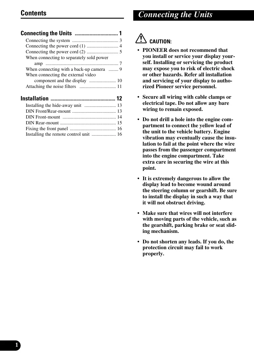
Connecting the Units 1
Connecting the system 3
Connecting the power cord (1) 4
Connecting the power cord (2) 5
When connecting to separately sold power amp 7
When connecting with a back-up camera 9
When connecting the external video component and the display 10
Attaching the noise filters 11
Installation 12
Installing the hide-away unit 13
DIN Front/Rear-mount 13
DIN Front-mount 14
DIN Rear-mount 15
Fixing the front panel 16
Installing the remote control unit 16

CAUTION:
- PIONEER does not recommend that you install or service your display yourself. Installing or servicing the product may expose you to risk of electric shock or other hazards. Refer all installation and servicing of your display to authorized Pioneer service personnel.
- Secure all wiring with cable clamps or electrical tape. Do not allow any bare wiring to remain exposed.
- Do not drill a hole into the engine compartment to connect the yellow lead of the unit to the vehicle battery. Engine vibration may eventually cause the insulation to fail at the point where the wire passes from the passenger compartment into the engine compartment. Take extra care in securing the wire at this point.
- It is extremely dangerous to allow the display lead to become wound around the steering column or gearshift. Be sure to install the display in such a way that it will not obstruct driving.
- Make sure that wires will not interfere with moving parts of the vehicle, such as the gearshift, parking brake or seat sliding mechanism.
- Do not shorten any leads. If you do, the protection circuit may fail to work properly.
Note:
- This unit is for vehicles with a 12-volt battery and negative grounding. Before installing it in a recreational vehicle, truck, or bus, check the battery voltage.
- To avoid shorts in the electrical system, be sure to disconnect the battery cable before beginning installation.
Refer to the owner's manual for details on connecting the power amp and other units, then make connections correctly. - Secure the wiring with cable clamps or adhesive tape. To protect the wiring, wrap adhesive tape around them where they lie against metal parts.
- Route and secure all wiring so it cannot touch any moving parts, such as the gear shift, handbrake and seat rails. Do not route wiring in places that get hot, such as near the heater outlet. If the insulation of the wiring melts or gets torn, there is a danger of the wiring short-circuiting to the vehicle body.
- Don't pass the yellow lead through a hole into the engine compartment to connect to the battery. This will damage the lead insulation and cause a very dangerous short.
- Do not shorten any leads. If you do, the protection circuit may fail to work when it should.
- Never feed power to other equipment by cutting the insulation of the power supply lead of the unit and tapping into the lead. The current capacity of the lead will be exceeded, causing overheating.
- When replacing fuse, be sure to use only fuse of the rating prescribed on the fuse holder.
- Since a unique BPTL circuit is employed, never wire so the speaker leads are directly grounded or the left and right speaker leads are common.
- If the RCA pin jack on the unit will not be used, do not remove the caps attached to the end of the connector.
- Speakers connected to this unit must be high-power types with minimum rating of 50W and impedance of 4 to 8 ohms. Connecting speakers with output and/or impedance values other than those noted here may result in the speakers catching fire, emitting smoke, or becoming damaged.
-
When this product's source is switched ON, a control signal is output through the blue/white lead and blue lead. Connect to an external power amp's system remote control or the car's Autoantenna relay control terminal (max. 300mA 12 V DC). If the car features a glass antenna, connect to the antenna booster power supply terminal.
-
When an external power amp is being used with this system, be sure not to connect the blue/white lead to the amp's power terminal. Likewise, do not connect the blue lead to the power terminal of the auto-antenna. Such connection could cause excessive current drain and malfunction.
- To avoid short-circuiting, cover the disconnected lead with insulating tape. Especially, insulate the unused speaker leads without fail. There is a possibility of short-circuiting if the leads are not insulated.
- To prevent incorrect connection, the input side of the IP-BUS connector is blue, and the output side is black. Connect the connectors of the same colors correctly.
- This unit cannot be installed in a vehicle that does not have an ACC (accessory) position on the ignition switch. (Fig. 1)

ACC position

No ACC position
Fig. 1
- The black lead is ground. Please ground this lead separately from the ground of high-current products such as power amps.
If you ground the products together and the ground becomes detached, there is a risk of damage to the products or fire.
- Cords for this product and those for other products may be different colors even if they have the same function. When connecting this product to another product, refer to the supplied manuals of both products and connect cords that have the same function.
Connecting the system

Fig. 2

Fig. 3
Connecting the power cord (2)
Note:
Depending on the kind of vehicle, the function of 3^ and 5^ may be different. In this case, be sure to connect 2^ to 5^ and 4^ to 3^ .

Cap (1*)
When not using this terminal, do not remove the cap.
Yellow (3*)
Back-up
(or accessory)

Red (5^*)
Accessory
(or back-up)
Yellow (2^*)
To terminal always supplied with power regardless of ignition switch position.

Red (4^*)
To electric terminal controlled by ignition switch (12 V DC) ON/OFF.
Orange/white
To lighting switch terminal.
Black (ground)
To vehicle (metal) body.
Blue/white (6^*)
ISO connector
Note:
In some vehicles, the ISO connector may be divided into two. In this case, be sure to connect to both connectors.
The pin position of the ISO connector will differ depending on the type of vehicle. Connect 6^ and 7^ when Pin 5 is an antenna control type. In another type of vehicle, never connect 6^ and 7^ .

This product
Connect leads of the same color to each other.
Fuse holder

Fuse resistor
Fuse resistor
Speaker leads
White: Front left
White/black: Front left
Gray: Front right
Gray/black: Front right
Green: Rear left
Green/black: Rear left
Violet: Rear right
Violet/black: Rear right

Violet/white
See the section "When connecting
with a back-up camera".
Yellow/black
If you use a cellular telephone, connect it via the
Audio Mute lead on the cellular telephone. If not,
keep the Audio Mute lead free of any connections.
Connection method

- Clamp the lead.


- Clamp firmly with needle-nosed pliers.
Note:
- The position of the parking brake switch depends on the vehicle model. For details, consult the vehicle Owner's Manual or dealer.
Light green
Used to detect the ON/OFF status of the parking brake.
This lead must be connected to the power supply side of the parking brake switch.
Blue/white
To system control terminal of the power amp (max. 300mA12V DC).

Blue (7^*)
To Auto-antenna relay control terminal
(max. 300mA12VDC)

Fig. 4
When connecting to separately sold power amp


Fig. 5
When connecting with a back-up camera
When using this product with a back-up camera, automatic switching to video from a back-up camera when the gear shift is moved to REVERSE (R) position is possible.

Connection method

1. Clamp the lead.


Fig. 6
- Clamp firmly with needle-nosed pliers.
Note:
- It is necessary to set to BACK UP CAMERA in SETUP when connecting the back-up camera.

Fig. 7
- It is necessary to set to AV INPUT in SETUP when connecting the external video component.
When using a display connected to rear video output
This product's rear video output is for connection of a display to enable passengers in the rear seats to watch the DVD or Video CD.
WARNING:
- NEVER install the display in a location that enables the Driver to watch the DVD or Video CD while Driving.
- NEVER connect rear audio output (REAR MONITOR OUT) to sold separately power amp.
Attaching the noise filters
To prevent the noise, use the supplied noise filters correctly.

Fig. 8
Note:
- Before finally installing the unit, connect the wiring temporarily, making sure it is all connected up properly, and the unit and the system work properly.
- Use only the parts included with the unit to ensure proper installation. The use of unauthorized parts can cause malfunctions.
- Consult with your nearest dealer if installation requires the drilling of holes or other modifications of the vehicle.
- Install the unit where it does not get in the driver's way and cannot injure the passenger if there is a sudden stop, like an emergency stop.
- Do not place the display in a position where it will impede the driver's visibility or affect the operation of your vehicle's air bags.
- The semiconductor laser will be damaged if it overheats, so don't install the unit anywhere hot — for instance, near a heater outlet.
- If installation angle exceeds 30^ from horizontal, the unit might not give its optimum performance. (Fig. 9)

Fig. 9
- To ensure proper heat dissipation of this product, take special care not to block the cooling fan side of this product.
- When mounting the hide-away unit, make sure none of the leads are trapped between the hide-away unit and the surrounding metalwork or fittings.
- Do not mount the hide-away unit near the heater outlet, where it would be affected by heat, or near the doors, where rainwater might splash onto it.
- Before drilling any mounting holes always check behind where you want to drill the holes. Do not drill into the gas line, brake line, electrical wiring or other important parts.
- If the hide-away unit is installed in the passenger compartment, anchor it securely so it does not break free while the car is moving, and cause injury or an accident.
- If the hide-away unit is installed under a front seat, make sure it does not obstruct seat movement. Route all leads and cords carefully around the sliding mechanism so they do not get caught or pinched in the mechanism and cause a short circuit.
Installing the hide-away unit
Mounting with Brackets

Drill 2 to 2.5mm diameter holes.
Fig. 10
Mounting with Velcro Tape
Thoroughly wipe off the surface before affixing the velcro tape.

Fig. 11
DIN Front/Rear-mount
This unit can be properly installed either from "Front" (conventional DIN Front-mount) or "Rear" (DIN Rearmount installation, utilizing threaded screw holes at the sides of unit chassis). For details, refer to the following illustrated installation methods.
Before installing the unit
- Remove the frame and the holder. (Fig. 12)
Pull out to remove the frame and then loosen the screws (2× 3mm) to remove the holder. (When reattaching the frame, point the side with a groove downwards and attach it.)

Fig. 12
Installation with the rubber bush
1. Decide the position of the side brackets. (Fig. 13)
When installing in a shallow space, change the position of side brackets. In this case, stick conceal tape on parts that protrude from the dashboard.

Fig. 13
2. Install the unit into the dashboard. (Fig. 14)
After inserting the holder into the dashboard, then select the appropriate tabs according to the thickness of the dashboard material and bend them. (Install as firmly as possible using the top and bottom tabs. To secure, bend the tabs 90 degrees.)

- After installing the unit into the dashboard, reattach the frame.
Fig. 14
DIN Rear-mount
Installation using the screw holes on the side of the unit
- Fastening the unit to the factory radio mounting bracket. (Fig. 15) (Fig. 16) (Fig. 17)
Select a position where the screw holes of the bracket and the screw holes of this product become aligned (are fitted), and tighten the screws at 2 places on each side. Use any of binding screws (4× 3mm) ,binding screws (5 × 6mm) or flush surface screws (5× 6 mm), depending on the shape of the screw holes in the bracket.
*1 Use binding screws (4 × 3 mm) only.

Fig. 15
- When installing in a shallow space, use the following screw holes. In this case, stick conceal tape on parts that protrude from the dashboard.

Fig. 16
Fig. 17

Factory radio mounting bracket *2
*2 If the screw holes of the bracket and the screw holes of this unit are not aligned, use a file to widen the screw holes of the bracket to match up the screw holes on this unit. Tighten the screws at 2 places on each side.
Fixing the front panel
If you do not operate the removing and attaching the front panel function, use the supplied fixing screws to fix the front panel to this unit.
Fix the front panel to the unit using fixing screws after removing the front panel. (Fig. 18)

Fixing screw
Fig. 18
Installing the remote control unit
When not using the remote control unit, secure it with velcro tape to prevent it from moving.
- Thoroughly wipe off the surface before affixing the velcro tape.

Fig.19
PIONEER ELECTRONICS (USA) INC.
P.O. Box 1540, Long Beach, California 90801-1540, U.S.A.
TEL: (800) 421-1404
PIONEER EUROPE NV
Haven 1087, Keetberglaan 1, B-9120 Melsele, Belgium
TEL: (0) 3/570.05.11
PIONEER ELECTRONICS ASIACENTRE PTE. LTD.
253 Alexandra Road, #04-01, Singapore 159936
TEL: 65-6472-1111
PIONEER ELECTRONICS AUSTRALIA PTY. LTD.
178-184 Boundary Road, Braeside, Victoria 3195, Australia
TEL: (03) 9586-6300
PIONEER ELECTRONICS OF CANADA, INC.
300 Allstate Parkway, Markham, Ontario L3R OP2, Canada
TEL: (905) 479-4411
PIONEER ELECTRONICS DE MEXICO, S.A. de C.V.
Blvd. Manuel Avila Camacho 138 10 piso
Col.Lomas de Chapultepec, Mexico, D.F. 11000
TEL: 55-9178-4270
先鋒股份有限公司
總公司:台北市中山北路二段44號13樓
電話:(02)2521-3588
先鋅電子(中國)有限公司
Published by Pioneer Corporation.
Copyright © 2003 by Pioneer Corporation.
All rights reserved.
Publication de Pioneer Corporation.
Copyright © 2003 Pioneer Corporation.